Article

Identification of Subsurface Mesoscale Crack in Full Ceramic Ball Bearings Based on Strain Energy Theory

1
School of Mechanical Engineering, Shenyang Jianzhu University, Shenyang 110168, China
2
School of Mechanical Engineering & Automation, Northeastern University, Shenyang 110819, China
*
Author to whom correspondence should be addressed.
Appl. Sci. 2023, 13(13), 7783; https://doi.org/10.3390/app13137783
Submission received: 15 May 2023 / Revised: 25 June 2023 / Accepted: 29 June 2023 / Published: 30 June 2023
(This article belongs to the Special Issue Fault Diagnosis and Detection of Machinery)

Abstract

:
Subsurface mesoscale cracks exist widely in the outer ring of full ceramic ball bearings (FCBBs), which is a potential threat for the stable operation of related devices such as aero engines, food processing machinery, and artificial replacement hip joints. This paper establishes a dynamic model of subsurface mesoscale cracks in the outer ring of FCBBs based on strain energy theory, and the influence of different crack lengths on the running state is analyzed. The existence of mesoscale cracks is regarded as weakening on the stiffness coefficient, and the deterioration degree of outer ring stiffness of subsurface cracks is thereby quantified. It is found that a small wave peak appears in the vibration time-domain signal when there is a mesoscale crack on the outer ring subsurface, and the crack evolution is evaluated by the amplitude of the corresponding feature frequency. Finally, the accuracy of the model is verified by experiments. The model realizes the identification and degree evaluation of subsurface mesoscale cracks in FCBBs, and provides theoretical references for the diagnosis and status monitoring for FCBB rotor systems.

1. Introduction

With the advantages of high hardness, low thermal deformation and low abrasive grain, full ceramic ball bearings (FCBBs) have important applications and prospects in fields such as aero engines, food processing machinery and artificial replacement hip joints [1,2,3]. However, when FCBBs are subjected to long-term uneven stress fields as well as alternating temperature conditions, internal early failures usually evolve into surface faults such as wear and spalling in the loaded zones [4,5,6], which not only weaken the overall stiffness characteristics of the bearing [7] but also affect the service life of the whole system. While the time-varying contact stiffness is an important index to characterize the operating condition of the bearing, and when subsurface cracks occur in the bearing, it leads to a reduction in contact stiffness [8,9], which is not conducive to the accurate operation of the ceramic bearing rotor system. Since the fault location and damage mechanism of FCBBs are different from those of steel bearings, the traditional steel bearing outer ring fault dynamics model cannot be directly transferred and applied to FCBBs. Considering that ceramic materials are more sensitive to local damage, it is significant to investigate the damage mechanism of subsurface mesoscale cracks in FCBBs.
For the study of the failure modes of various components of bearings, the bearing dynamic models have been widely adopted. Petersen et al. [10] proposed a method to calculate the quasi-static load distribution and changing stiffness of bearings with raceway defects of different depths, lengths, and surface roughness, and verified the correlation between low- and high-frequency events of ball entering and exiting defects and the dynamic characteristics of bearings. Liu et al. [11] investigated the wear-loss behavior of bearings using a whole-life test method to reveal the bearing surface damage and failure evolution process. For the study of subsurface failures in steel bearings, Deng et al. [12] studied subsurface fatigue crack expansion under rolling contact fatigue based on stress intensity factor calculations to assess fatigue crack expansion. Liu et al. [13] proposed a finite element model to study the effect of horizontal and inclined subsurface cracks on the contact characteristics of roller bearings, and obtained the relationship between contact deformation and crack dimensions (length, depth, and angle). Danielsen et al. [14] investigated the damage pattern of white etched cracks on ceramic bearings, and the test results showed that the stresses were significantly concentrated near the defect area. Li et al. [15] carried out research on FCBB, and proposed a stiffness evaluation model to obtain a mapping relationship between subsurface cracking and dynamic response. The mechanical properties of ceramic materials have also been extensively investigated using the relevant theories of fracture mechanics [16,17,18]. Wu et al. [19] considered the nonlinear contact stiffness and damping of ceramic bearings in terms of energy conservation. In this way, a more accurate differential equation for the vibration of angular contact ball bearings was developed. Our previous studies [20,21,22] also provided insight into cracking in FCBBs, and the cracks were proved to be related to contact stresses between the rolling element and the bearing collar during the operation of the equipment. However, the bending stresses exerted on the outer ring by the rolling element during its passage through the outer ring failure location was not taken into consideration, which was also a main cause for the generation and extension of internal defects. Researchers [23,24] have carried out in-depth analyses on the mechanism of crack formation under contact stresses. Based on the principles of fracture mechanics, the effect of cracking on stiffness due to bending moments can be analyzed through changes in strain energy [25,26]. As a result, the crack identification method based on strain energy is a potential way to solve the problem since the failure modes in traditional models are no longer applicable.
This paper proposes a nonlinear dynamic model containing subsurface mesoscale cracks in the outer ring of FCBBs, and analyses on the dynamic response are thereby carried out. The fracture mechanics and strain energy theories of brittle materials are introduced, and changes in dynamic stiffness of the bearing with crack lengths are analyzed based on the trend of strain energy. The model is presented in Section 2, and numerical simulations are carried out in Section 3 to illustrate the effects of different lengths of mesoscale cracks. Experimental verification is carried out in Section 4, and discussions and conclusions are drawn in Section 4 and Section 5.

2. Dynamic Models Containing Subsurface Mesoscale Fault

2.1. Stiffness Weakening Coefficient and Strain Energy Release Rate

Different from steel bearings, FCBBs are usually made through hot isostatic pressing processes, and therefore contain submillimeter or even millimeter subsurface mesoscale cracks. The mesoscale crack extends continuously in the uneven stress field, and finally leads to breakdowns. Considering the load distribution at the crack area, each subsurface mesoscale crack is located within the elliptical region. The wing cracks in the brittle ceramic material are divided into two categories, the transverse crack leading to material cracking and the longitudinal crack leading to weakening of the bearing outer ring stiffness. Here, the outer ring with mesoscale cracks is taken as an example, and the mesoscale cracks are shown in Figure 1.
Due to the presence of wing crack clusters in the outer ring, this paper discusses the weakening of the outer ring stiffness of FCBBs caused by mesoscale cracks, mainly for longitudinal cracks. The longitudinal cracks are difficult to observe or detect directly, but have significant impacts on the stiffness of related components. It was found in previous studies [1,27] that the momentum inertia with mesoscale faults was proportional to the original inertia, as shown below
E I C = μ c E I
where E is the modulus of elasticity of ceramic material, I is the section moment of inertia for a healthy outer ring, and IC is the section moment of inertia for an outer ring with cracks. Combined with the different weakening of the bearing outer ring stiffness by different crack lengths, the composite stiffness weakening coefficient μ c is obtained for mesoscale faults as follows:
μ c = 1 1 / μ 1 2 / 3 + 1 / μ 2 2 / 3 3 / 2
where μ 1 , μ 2 represent the stiffness weakening coefficients of an FCBB outer ring containing crack and defects, respectively, where μ 1 = EI C 1 / EI , μ 2 = EI C 2 / EI , IC1 and IC2 represent the moment of inertia of FCBB outer ring with cracks and defects, respectively.
Since the main cause of subsurface mesoscale crack generation in the rotation of FCBBs is the bending load, the applied bending moment not only promotes the occurrence of tip crack expansion, but also increases the strain energy of the structure. The cracks mentioned in this paper are cracks of opening mode. A schematic diagram of subsurface cracks and local sections of the outer ring is shown in Figure 2.
The strain energy release rate of the outer ring of the FCBB under external additional load is expressed as
S E R R = K I 2 E
where K I is the strength coefficient of the crack calculated by the open displacement method. K I is expressed as
K I = M e S b π d Q
where M e is the surface correction factor, S b = 3 M / b a 2 , d is the radial depth of the subsurface cracks, a is the length from the top of the crack to the outer surface of the outer ring, and b is the length from the center of the crack to the side of the outer ring. In general, the surface correction factor M e is related to the crack–outer ring thickness ratio d/a, the crack length–outer ring width ratio c/b, and the crack tip angle φ. Newman and Raju gave an expression for the surface correction factor [28].
M e = H d a , φ F d a , c b , φ
The functions H(∙) and F(∙) in the formula can be calculated using the reference [29]. In addition, it should be noted that d/a and c/b have corresponding ranges of values. Q is the crack shape factor. According to the literature, we obtain
Q = 1 + 1.464 a c 1.65
where c is the width of the mesoscale crack.

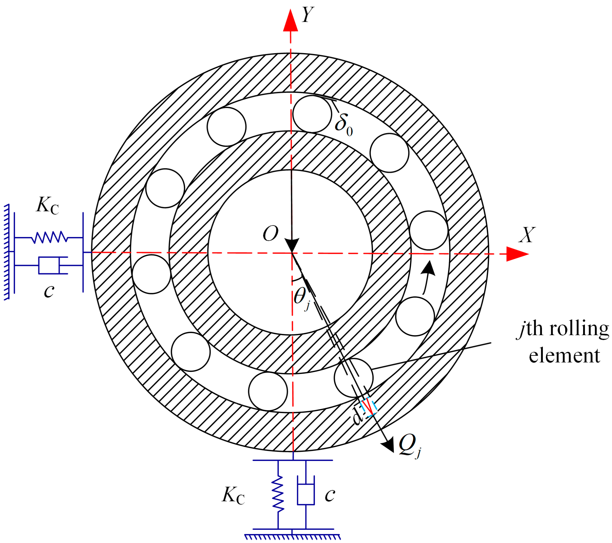
2.2. FCBB Outer Ring Contact Load

In this paper, the load that the FCBB is subjected to during operation is set as radial load, which is transferred between the inner and outer rings of the bearing through the rolling element. Hertz contact theory is approximately satisfied between the rolling element and the outer ring, and its crack profile is shown in Figure 3.
Based on Hertz point contact theory, x is the axial direction and y is the radial direction of the axis. The contact forces fx, fy are obtained by the accumulation of contact forces on each rolling element:
f x = j = 1 N b G ( δ j ) Q j cos θ j
f y = j = 1 N b G ( δ j ) Q j sin θ j
where G(∙) is the Heaviside function, with G(δj) = 1 when δj is positive and G(δj) = 0 when δj is negative or 0.
The forces on the rolling element and the outer ring of the bearing are modeled as
Q j = K c δ j n
where Kc is the contact stiffness, δ j is the jth rolling element contact deformation, n indicates the contact deformation coefficient, and n = 1.5 is generally selected for rolling bearings. The deformation of the rolling element is expressed as
δ j = x cos θ j 2 + y sin θ j 2 δ 0
where δ 0 is the radial clearance of the FCBB, and θ j is the angular position of the jth rolling element. Assuming that there is no sliding friction between the rolling element and the inner and outer raceway, the angular position of the rolling element can be expressed as
θ j = ω c t + 2 π ( j 1 ) / N b
where ω c is the cage speed, Nb is the number of rolling elements, the cage speed is related to the rotor speed ω s , and ω s is related to the composition of the FCBB. The cage speed is shown as
ω c = B ω s
where B = D i / ( D i + D o ) ; for FCBB, Di is the inner ring diameter of bearing, and Do is the outer ring diameter of bearing.
When the FCBB is subjected to a force along the vertical direction, the direction of the force is vertical downward. The type of the FCBB in this study is 6304, the force on the upper part of the bearing by the rolling element under radial load is neglected, and the load distribution Q φ on the outer ring of the bearing is expressed as shown in Figure 4.
The load distribution calculation formula is expressed as:
Q φ = Q max 1 1 2 k L 1 cos φ 3 2 φ φ load 0 others
where Qmax is the maximum load distribution density, φ is the arbitrary position angle in the load region, and kL is the load distribution coefficient, which is expressed as
k L = 1 2 1 δ 0 2 δ max
where δ 0 is the radial clearance of rolling bearing, and δmax is the maximum radial offset of the bearing.

2.3. Time-Varying Stiffness and Dynamic Model for Subsurface Crack Locations in Full Ceramic Outer Ring

According to the strain energy theory of ceramic materials, when there is an external moment acting at the subsurface cracks, the final strain energy generated on the outer ring is decomposed as the sum of the strain energy of the outer ring without subsurface cracking failure and the strain energy generated by the extension of the crack-containing failure [30]. Then there is
W = E N c + Δ U = 2 Δ U
and we have
E N c = Δ U
where ENc is the energy released by the expansion of mesoscale crack failure, ∆U is the increase of elastic strain energy when the crack failure occurs in the outer ring, and the final strain energy when the crack failure occurs in the outer ring is
U c = U + Δ U = U + E N c
where U is the strain energy of the outer ring of the FCBB in the case of no failure. For the outer ring of a normal bearing with bending stiffness EI, the strain energy of the bearing outer ring when subjected to a pure bending moment M is expressed as
U = 1 2 M 2 E I dx
According to the load distribution, the bending moment at the location of the subsurface mesoscale crack failure is calculated as
M = Q φ r cos φ d φ
According to the fracture mechanics considerations, the energy consumed by the extension at the location of the failure of the mesoscale crack is shown as
E N c = ( S E R R ) d A
Combining Equations (15)–(20), the relationship between the time-varying stiffness at the subsurface of the outer ring with a mesoscale crack failure and the stiffness at the normal location of the outer ring is calculated through
1 2 M 2 E I C d x = 1 2 M 2 E I d x + ( S E R R ) d A
where EIC is the bending stiffness of the outer ring of the FCBB in the event of a mesoscale crack failure. According to the structural dynamics, the bending moment EI is equivalent to the contact stiffness of the outer ring
K o = f E I
Therefore,
K c = μ c K o
Then, the actual contact stiffness of the mesoscale crack failure is obtained based on Equations (21)–(23) as
K c = 1 1 / μ 1 K o 2 / 3 + 1 / μ 2 K o 2 / 3 3 / 2
The two-degree-of-freedom mass-spring rotor-bearing system model used in this paper was proposed by Sunnersjö [31]. The rotor is simplified to a central point of concentrated mass with two identical bearings at each end. It is assumed that the outer ring of the bearing is fixed to the rigid support, while the inner ring of the bearing is fixed to the rotating shaft by means of an interference fit. It is assumed that the rolling element of the bearing is elastically deformed. The FCBB is simplified as a spring and damping system. The gyroscopic moment, centrifugal force, and lubrication traction between the bearing components are neglected [32]. Moreover, in the ceramic bearing rotor system, the stiffness of each component is relatively large, and the flexible deformation of the rotating shaft and bearing foundation is almost negligible. Therefore, in order to simplify the calculation, we consider ignoring the flexible factor [33]. The bearing is set to be placed vertically, subjected to a vertical downward radial force, and the line of action of the radial force passes through the center of the bearing. The contact deformation between the rolling element and the ceramic outer ring are regarded as complete elastic deformation, so the Hertz contact theory is still applicable to the model of the FCBB outer ring. Based on the load distribution and the contact deformation between the rolling element and the outer ring, the generalized contact force is obtained according to the Hertz contact theory, as shown in Figure 5. Combining the strain energy release rate, load distribution, and time-varying stiffness of the faulty outer ring, a two-degree-of-freedom nonlinear dynamics model is established as follows:
m x ¨ y ¨ + c x ˙ y ˙ + j = 1 N b G ( δ j ) Q j cos θ j j = 1 N b G ( δ j ) Q j sin θ j = 0 F r
where m is the FCBB outer ring mass, cz is the ceramic material damping coefficient, and Fr is the external additional load.
Combined with the effects of different crack fault depths on the weakening of the contact stiffness, the weights of each stage of the fault are quantified, the contact stiffness KC is imported in the dynamics model, and the FCBB outer ring subsurface mesoscale crack fault model is obtained. The flowchart of the calculation is shown in Figure 6.

3. Numerical Simulation

The type of the FCBB in the simulation is selected as 6304, and the parameter table is shown in Table 1. The radial load is Fr = 50 N. The crack length–outer ring thickness e is set as e = 0–0.8 mm, and the step is 0.2. The spindle speed is set to 1800 r/min. The fourth-order Runge–Kutta algorithm is used to solve the differential equation, and the vibration displacement responses of the outer ring with different crack sizes are analyzed.
According to Equations (1) and (2), the change of stiffness weakening coefficient is obtained. In order to quantify the subsurface mesoscale cracks more easily, the crack length-outer ring thickness e = d/a is selected as an indicator. To quantify the change in the stiffness weakening factor more intuitively, the absolute value of the change rate |h| = |∆μ/∆e| is shown in Figure 7.
As shown in Figure 7, the bearing outer ring stiffness weakening coefficient first shows a slow decline, then has a sharp decline, and finally comes to stabilization. At the stage of e = 0–0.18, the mesoscale cracks start to appear on the outer ring, the stiffness of the outer ring starts to be weakened by the appearance of mesoscale cracks, and the stiffness weakening curve decreases slowly. With the increase of the crack depth, the stiffness weakening becomes more and more obvious at the stage of e = 0.18–0.7, and the overall stiffness weakening curve shows a linear downward trend. At the stage of e = 0.7–0.8, the stiffness weakening curve tends to be stable.
Generally, with the increase of crack radial depth, the effect on the stiffness weakening coefficient increases first and then decreases, indicating that the subsurface crack continuously weakens the stiffness of the bearing outer ring. According to the change in |h|, the change rate of the stiffness weakening reaches the peak value at e = 0.58, and then starts to come down. The actual contact stiffness change curve is obtained according to Equations (21)–(23), and in order to quantify the actual contact stiffness change more intuitively, the absolute value of change rate |i| = |∆KC/∆e| is selected as an indicator, as shown in Figure 8.
It is seen in Figure 8 that the actual contact stiffness of the outer ring shows an overall trend of slow decline followed by a sharp fall. At the stage of e = 0–0.12, the crack depth is not obvious compared with the outer ring thickness, and only slow descent is seen in the stiffness. At the stage of e = 0.12–0.8, subsurface mesoscale cracks continue to increase along the outer ring radial depth, and the actual contact stiffness shows a roughly linear decreasing trend as the healthy thickness without cracks is becoming smaller. Then, it is inferred that with the increase of crack depth, the deformation resistance between the rolling elements and the outer ring decreases under the action of radial force.
The contact stiffness of the outer ring becomes smaller due to the existence of subsurface mesoscale cracks. The contact force between the rolling element and the inner raceway of the bearing outer ring fluctuates, so an additional displacement appears in the fault area. In the process of crack depth change, three representative depths with e = 0.2, 0.4, and 0.8 are selected to observe the effect of mesoscale cracks on the FCBB dynamic response. The time-domain signals with healthy outer ring and with outer ring cracks are obtained by numerical simulation. In the time-domain signal, a signal peak appears near the small value between the maximum value and the minimum value, which presents a periodic impact phenomenon, as shown in Figure 9 and Figure 10, respectively.
It is seen from the results that when there is no fault in the bearing, the dynamic response is close to sinusoidal, and the contact force between the rolling element and the inner raceway of the outer ring of the bearing is periodic and fluctuates with equal amplitude. When the mesoscale crack starts to make impact, there are obvious periodic impacts with small peaks, and the contact force between the rolling element and the inner raceway of the outer ring of the bearing is periodic and fluctuates with unequal amplitude. The amplitudes of the overall vibration and the small wave peak rise with the increase of crack depth, which indicates that the crack length has a significant effect on the motion of the outer ring of the FCBB. As a result, the presence of small wave peak in the time-domain signal can be used as the evaluation criterion of subsurface mesoscale crack faults in the FCBB outer ring.
However, the small wave peaks in the time domain are not obvious enough, and are likely to be covered by strong noise in actual measurement. In order to make a more accurate quantitative analysis of the crack in the outer ring of FCBB, the fast Fourier transform (FFT) and the empirical modal decomposition (EMD) method is carried out in the processing of the time-domain signal. The frequency-domain signal and fourth-order modal decomposition at the location of the crack in the outer ring of the FCBB are obtained, as shown in Figure 11 and Figure 12.
The contact force between the rolling element and the inner raceway of the outer ring fluctuates due to the existence of mesoscale cracks, resulting in additional displacement, which leads to the existence of small wave peaks in the vibration signal. After FFT, a peak corresponding to the small wave peak appears and fBPOF is the fault frequency of the bearing outer ring, as shown in Figure 11. The new peak frequency appears near the rotating frequency f0, and with the increase of crack depth, the amplitude corresponding to the small wave peak in frequency domain increases.
As shown in Figure 12, after EMD processing, the intrinsic mode function (IMF) components represent the frequency components of the original signal and are arranged in order from high frequency to low frequency. The first image represents the original signal, followed by the three components obtained from EMD decomposition, called IMF1~IMF3. Each IMF component represents an intrinsic modal component present in the original signal. IMF3 corresponds to the lowest frequency component, and according to the decomposition order of EMD, its amplitude matches the amplitude of the lowest frequency in the frequency domain. Therefore, IMF3 corresponds to the frequency of the small wave peak in the time-domain signal, and its amplitude is an important indicator to determine the evolution of the trend of the mesoscale crack in the outer ring of the FCBB, which provides a reference for the evolution of the subsurface crack in the FCBB.

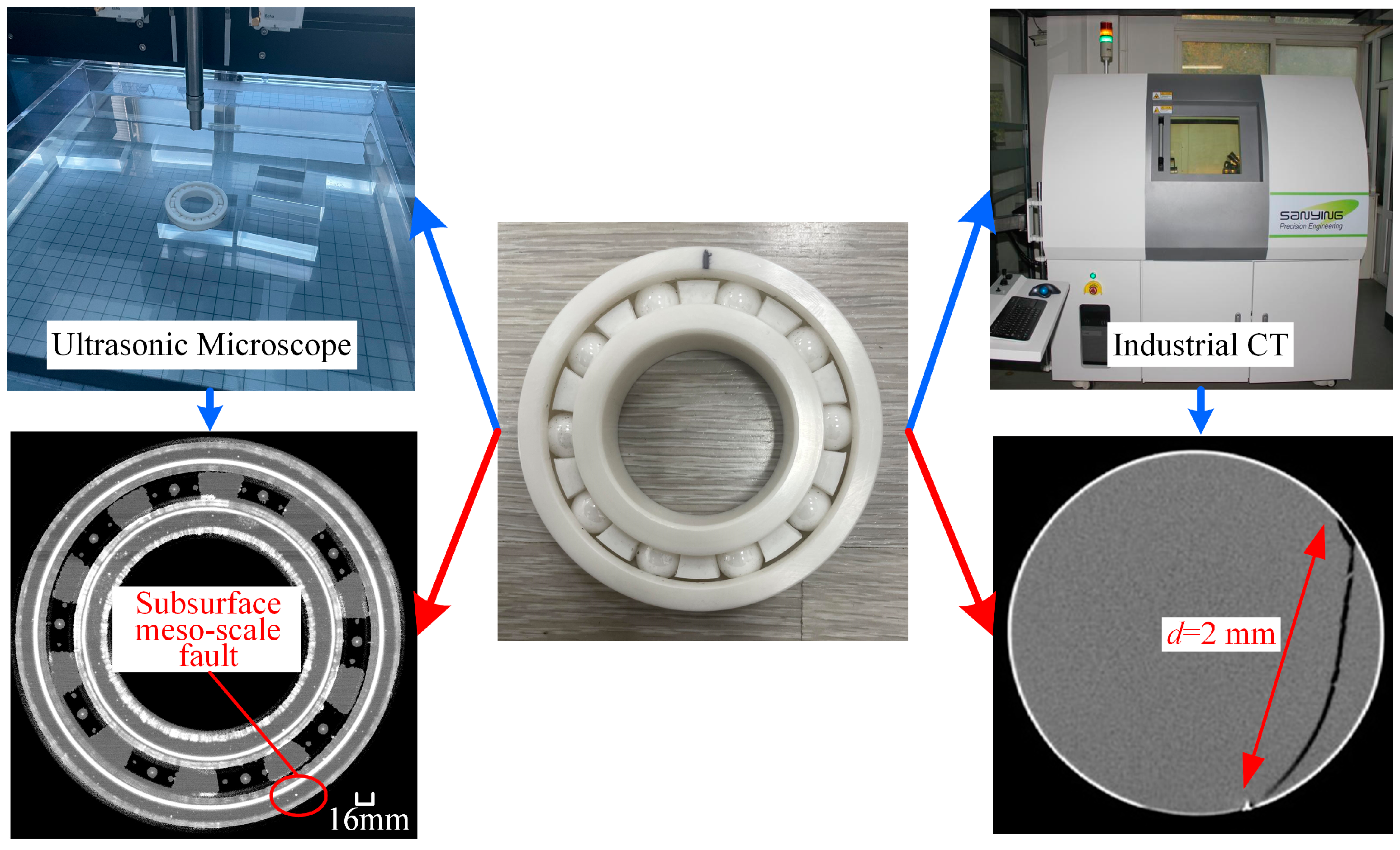
4. Experimental Investigation

To check the accuracy of the proposed method, an experiment was conducted on the rotor bearing test rig. The FCBB was equipped in the test rig, and the system was driven by a motor, as shown in Figure 13. Test bearings were inch type R16 bearings. The test parameters are given in Table 2.
In order to obtain the effect of subsurface mesoscale cracks on running performance of FCBB, two samples of healthy FCBB(zirconia) were set to run continuously at radial force of 300 N and operating speed of 1800 r/min for 50 h. Then, the two faulty bearings were tested through ultrasonic testing equipment and industrial computerized tomography (industrial CT), respectively. The obtained faulty bearings were placed on the “MFS-MG mechanical fault comprehensive simulation experimental bench” for testing. The results are displayed in Figure 14.
As shown in Figure 14, the nondestructive testing methods provided the internal morphology of the FCBB. After continuously running for 50 h, some subsurface mesoscale cracks started to appear in FCBB, and are seen in ultrasonic results as dots. In the industrial CT results, a mesoscale crack with a depth of about d = 2.0 mm is seen clearly.
The tested bearing was then installed in the test rig again to obtain the dynamic response with mesoscale cracks, and displacement sensors were arranged on the pedestal to collect the signals. The signals were transmitted to the data collector for further processing. The vibration signal is shown in Figure 15a, and the corresponding simulation result is given in Figure 15b.
As shown in Figure 15, at the crack length d = 2.0 mm, periodic small wave peaks appear in the time-domain signal of the test bearing, which is consistent with the simulation results. The existence of small wave peaks in the test signal determines the existence of subsurface mesoscale cracks in the outer ring of the bearing, and the accuracy of the proposed model is thus verified. However, the amplitudes of both the overall vibration signal and the small wave peaks are influenced by the background noise and other vibration sources, and the recognition of the small wave peaks is also affected. The collected vibration signal is transformed into frequency domain through FFT to obtain the frequency components, as shown in Figure 16.
As shown in Figure 16, f0 is the rotational frequency. The amplitude corresponding to the frequency of small wave peak is more prominent, which is the same as the simulation results in Figure 11. Thus, it is concluded that the frequency component signifies the existence of mesoscale cracks; it is easier to recognize and is more decisive for the quantization of subsurface faults.

5. Discussion

Combining the fracture mechanics of ceramic materials and FCBB strain energy theory, the weakening effect of subsurface cracks on contact stiffness is quantified in this paper. The stiffness evaluation model of an FCBB with subsurface cracks in the outer ring is established, which judges whether there are subsurface mesoscale cracks in the outer ring of the FCBB and the degree of crack evolution. The mapping relationship between the subsurface crack and the dynamic response is obtained. The modified model effectively provides a basis for predicting and analyzing the degradation performance of the FCBB.
According to the simulation and experimental results, when the ratio e of the subsurface mesoscale crack length to the radial thickness of the bearing is 0.1, the crack length has little effect on the stiffness weakening of the bearing. When the ratio e is 0.1–0.58, the stiffness weakening phenomenon of the crack length increases gradually, and when the ratio e reaches 0.58, the stiffness weakening phenomenon reaches its peak. The increase in crack length itself has a weakening effect on the contact stiffness, but at the same time it also serves to reduce the impact. It may be a nonlinear coupling phenomenon under the dual influence of stiffness weakening and vibration reduction, which is worthy of attention in the subsequent analysis of fault stiffness characteristics of FCBBs. For the flexible factors of rotating shaft and bearing foundation, the length of rotating shaft in this paper is not long and the slenderness ratio is not large, so the influence of flexibility on mesoscale crack detection is not obvious. At the same time, for the bearing rotor system, the deflection (flexibility) of the rotating shaft directly affects the eccentricity and axial force, which is mainly reflected in the overall amplitude of dynamic characteristics, and has little influence on the feature extraction of cracks. When the crack exists, it has a great influence on the radial stiffness, so it has an obvious influence on the radial vibration. Considering that cracks can also have a certain impact on axial vibration, it is worth conducting detailed research on axial vibration in the future.

6. Conclusions

(1)
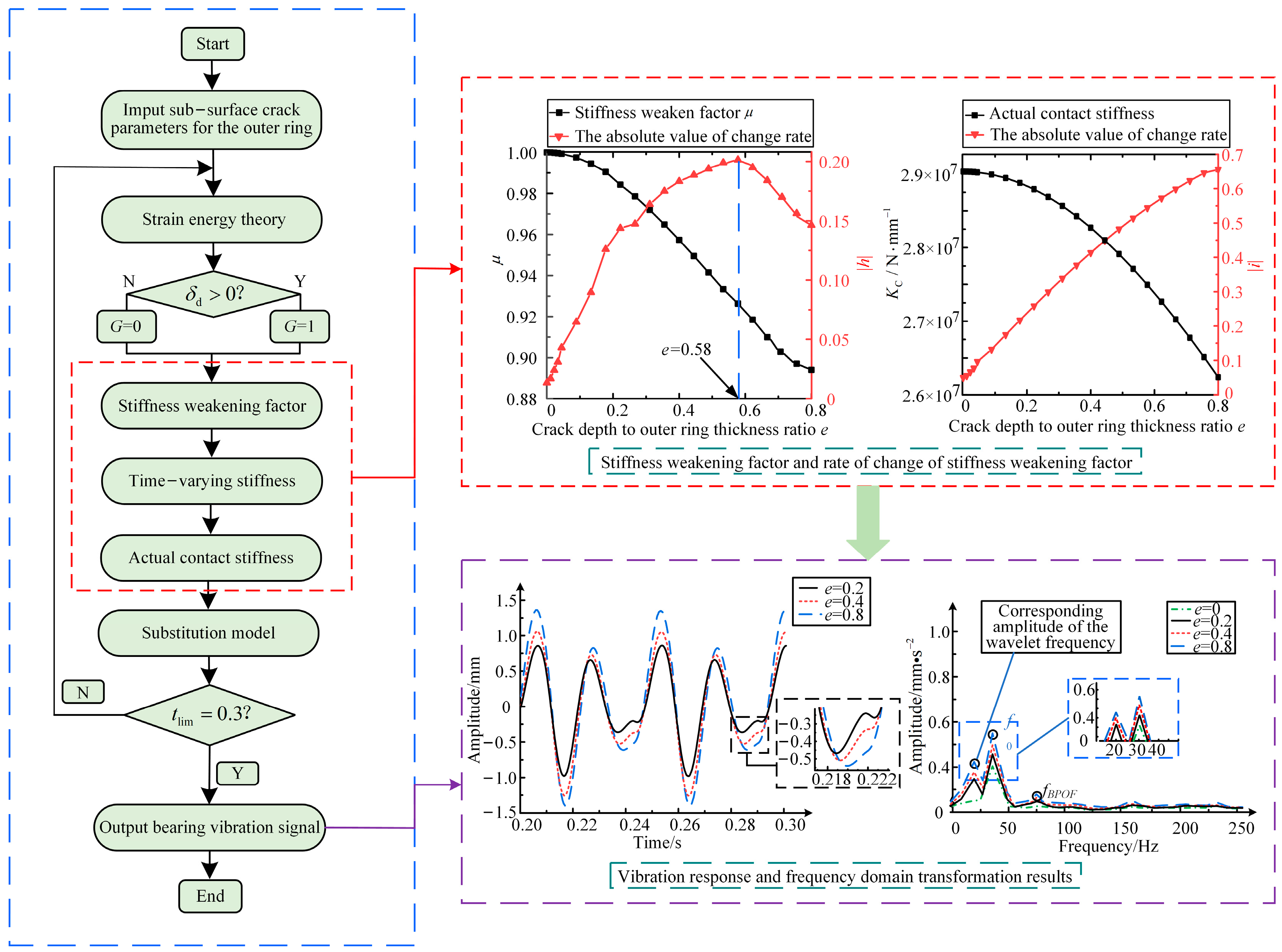
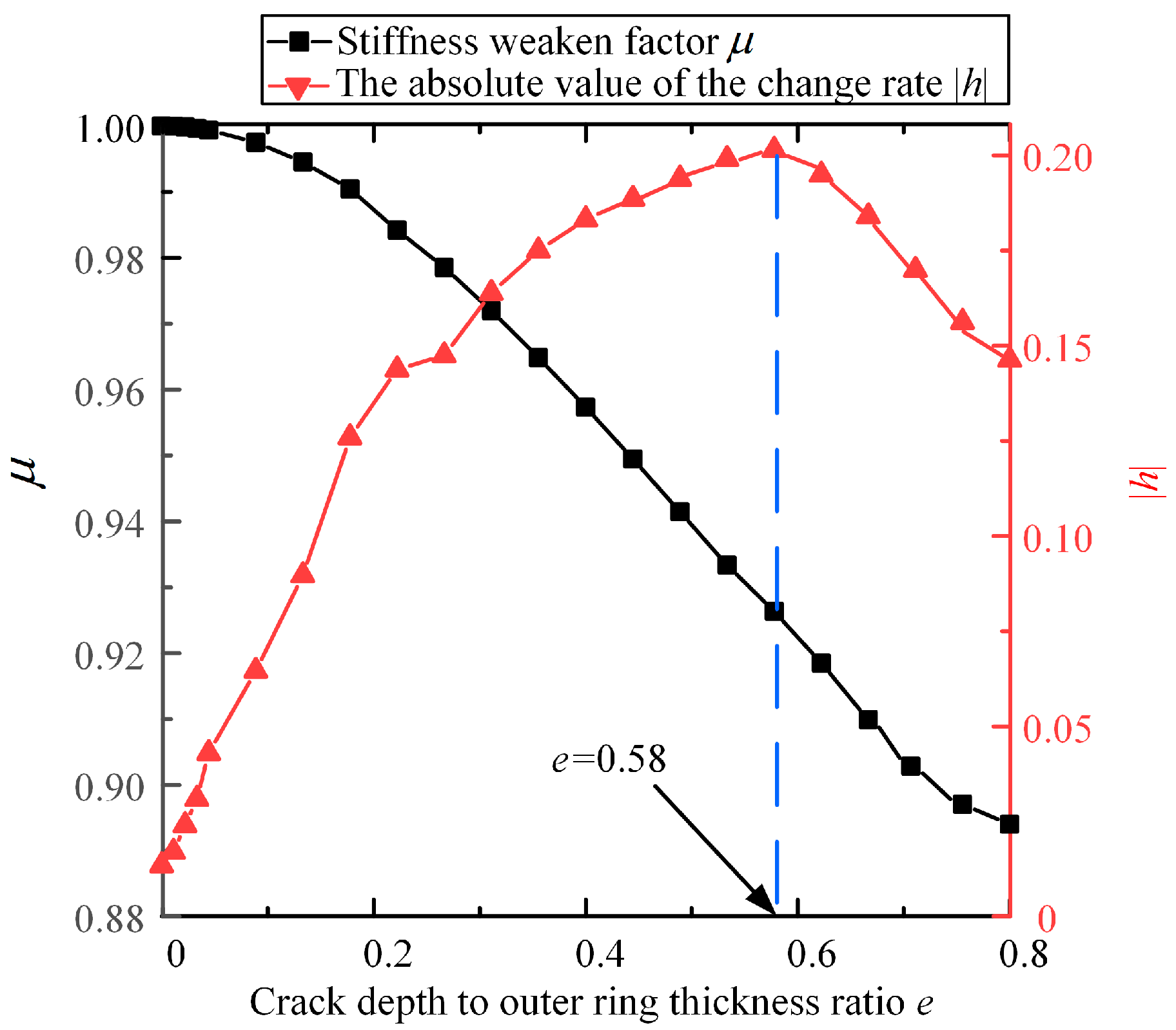
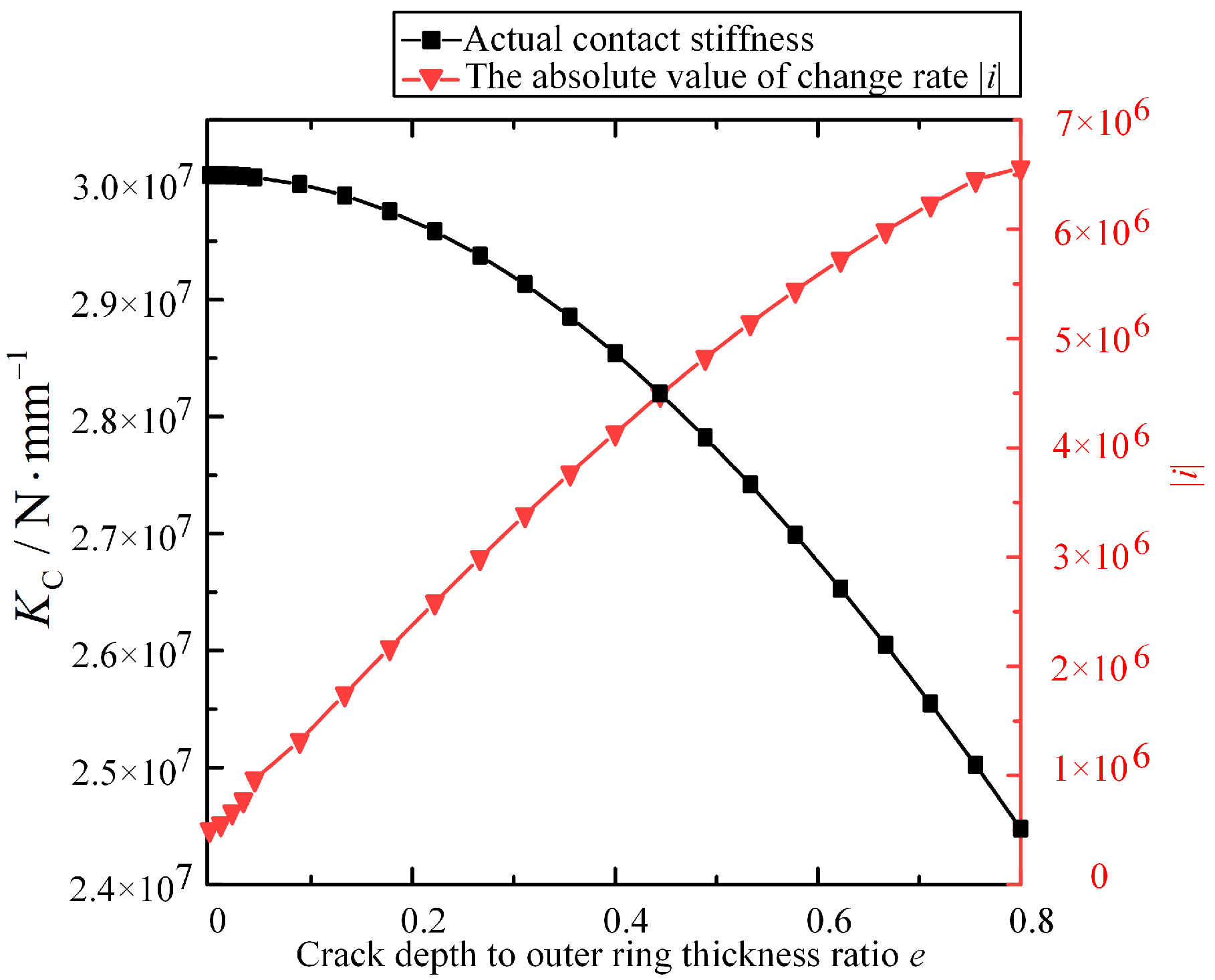
This paper proposes a dynamic model based on the strain energy theory of ceramic materials for the failure of mesoscale cracks on the outer ring subsurface of FCBB. Based on this model, the weakening coefficient of the outer ring stiffness of bearings is found to decrease slowly at first, then comes down sharply, and finally becomes stable. The actual contact stiffness first decreases monotonously, which signifies that the stiffness weakening brought about by the cracks is fatal.
(2)
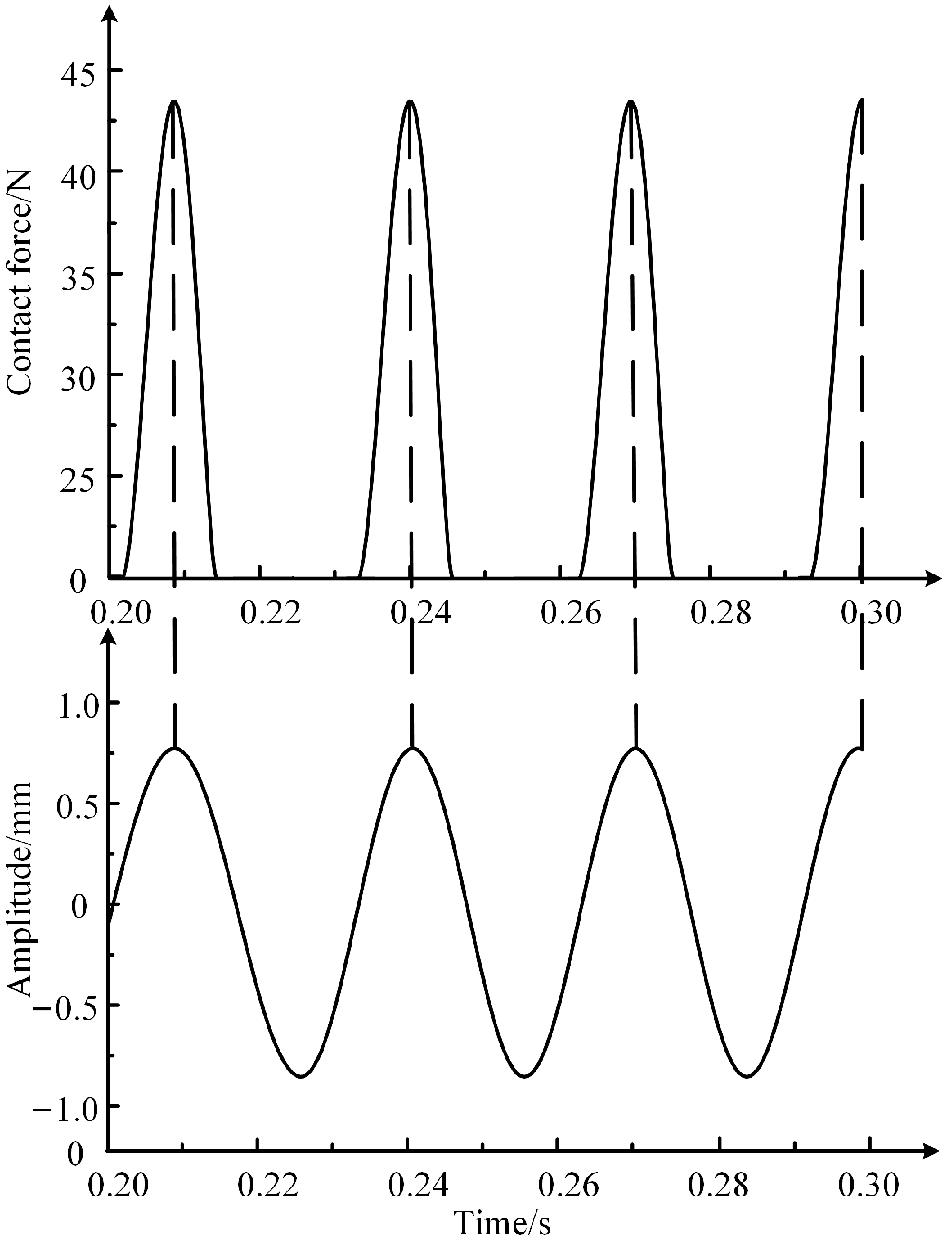
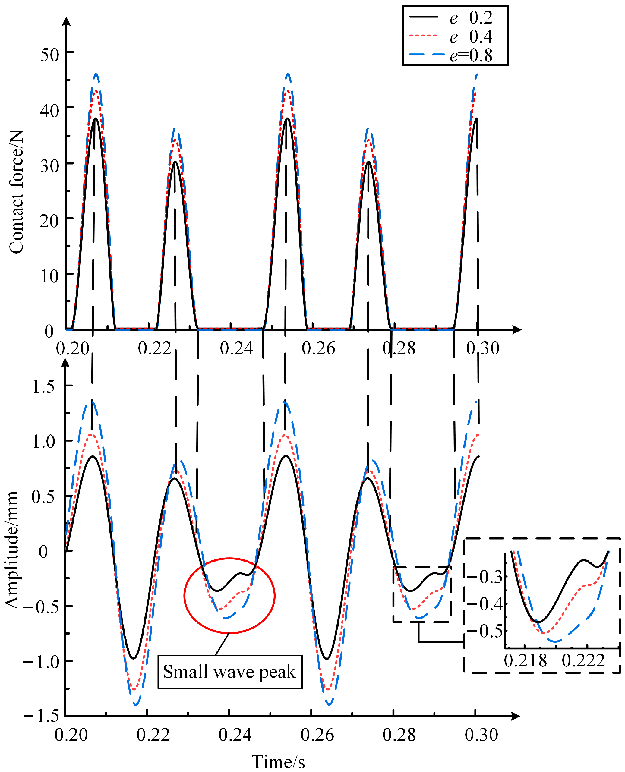
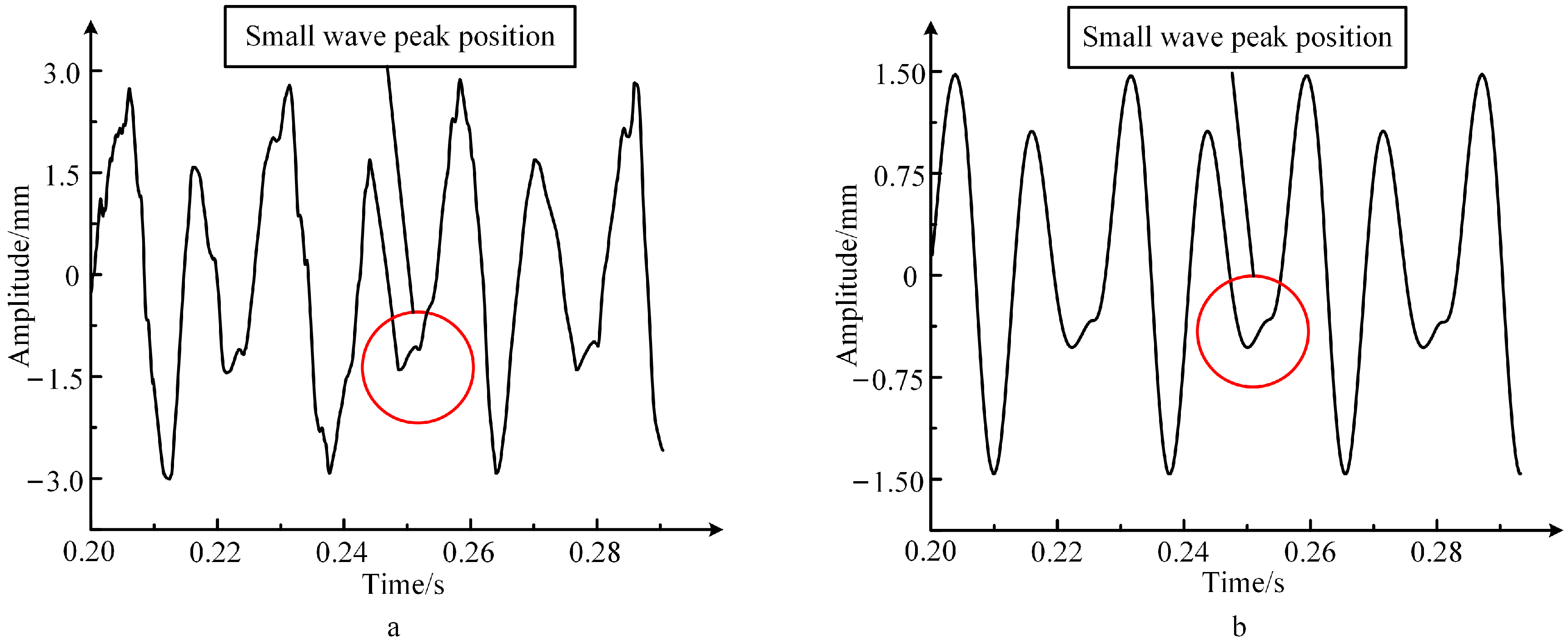
When there are mesoscale cracks in FCBB, small periodic wave peak is seen in the vibration time-domain signal, and the height of the wave peak increases with the radial length of the mesoscale cracks. The small wave peak is used as a preliminary indication for mesoscale cracks, and the height of small wave peaks reflects the degrees of crack evolution.
(3)
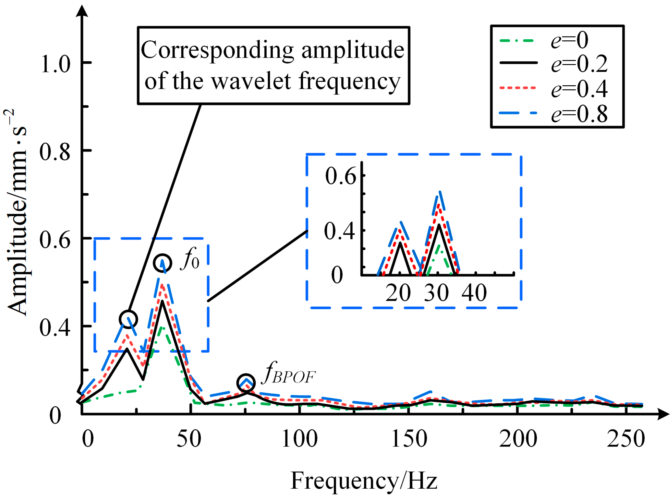
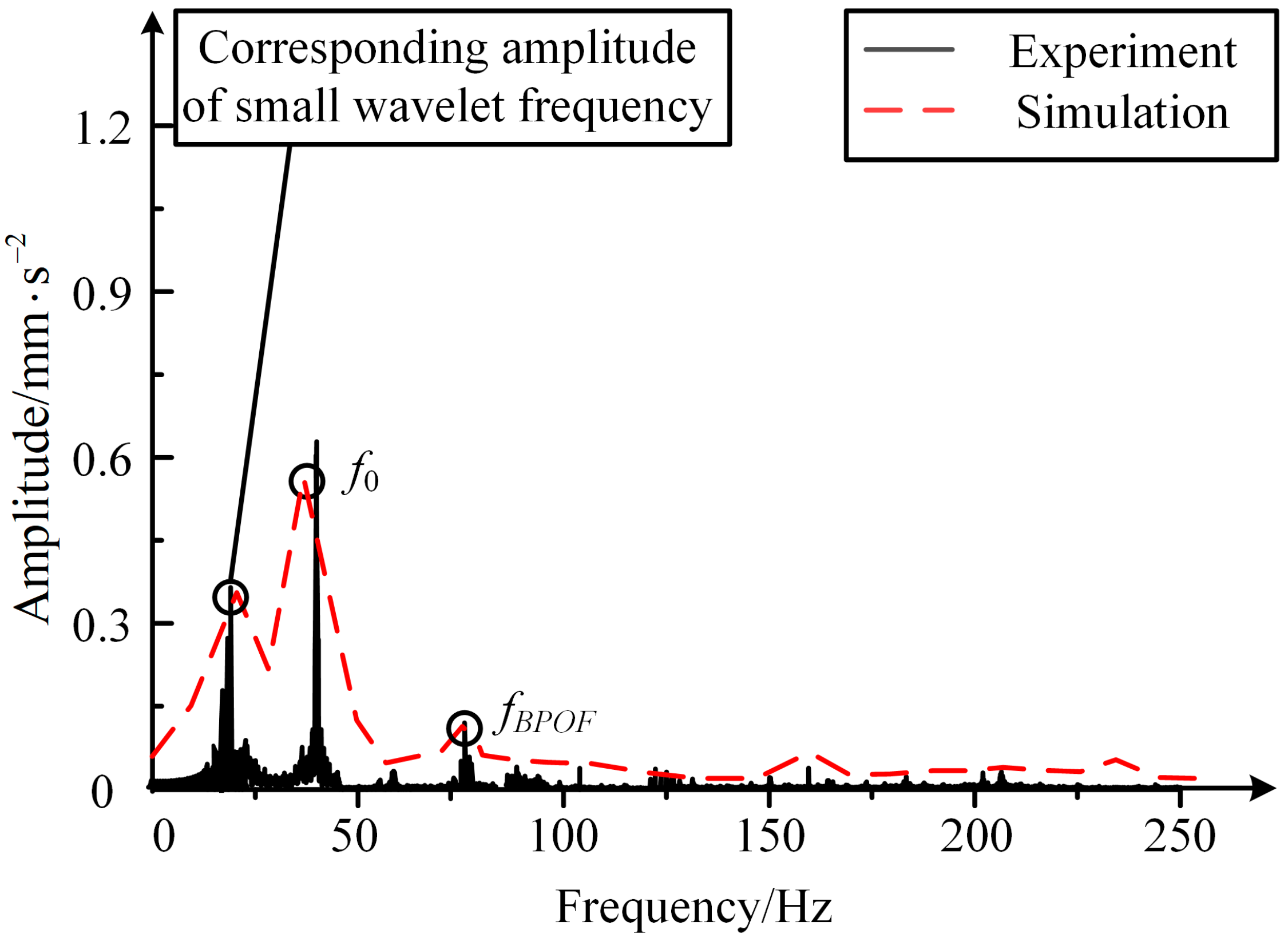
The subsurface mesoscale cracks also lead to changes in frequency-domain results of the FCBB dynamic response, and a special characteristic frequency appears near the rotating frequency. The height of its amplitude can be used to indicate the degree of crack evolution, and is more decisive for fault detection and evaluation.

Author Contributions

X.B.: Methodology, writing—original draft, writing—review and editing. Z.Z.: simulation, and experiment. H.S.: Conceptualization, methodology, and funding acquisition. Z.L.: Investigation, formal analysis. T.L.: Investigation and software. All authors have read and agreed to the published version of the manuscript.

Funding

This research was funded by National Science Foundation of China (grant number 52275119, 52075348), Key Laboratory of Vibration and Control of Aero-Propulsion System (Grant no. VCAME202203), and Education Department Project of Liaoning Province (LJKZZ20220078).

Institutional Review Board Statement

Not applicable.

Informed Consent Statement

Not applicable.

Data Availability Statement

The data presented in this study are available on request from the corresponding author.

Acknowledgments

The authors thank National Science Foundation of China, Key Laboratory of Vibration and Control of Aero-Propulsion System and Education Department Project of Liaoning Province for funding this research, as well as the anonymous reviewers for their contribution to this paper.

Conflicts of Interest

The authors declare no conflict of interest.

References

  1. Shi, H.; Hou, M.; Wu, Y.; Li, B. Incipient fault detection of full ceramic ball bearing based on modified observer. Int. J. Control. Autom. Syst. 2022, 20, 727–740. [Google Scholar] [CrossRef]
  2. Xia, Z.; Wu, Y.; Ma, T.; Bao, Z.; Tian, J.; Gao, L.; Sun, J.; Li, S. Experimental study on adaptability of full ceramic ball bearings under extreme conditions of cryogenics and heavy loads. Tribol. Int. 2022, 175, 107849. [Google Scholar] [CrossRef]
  3. Sun, J.; Wu, Y.; Yang, J.; Yao, J.; Xia, Z.; Ma, T.; Luo, J. Friction properties and distribution rule of lubricant film of full ceramic ball bearing under different service condition. J. Ceram.-Silikáty 2022, 66, 54–65. [Google Scholar] [CrossRef]
  4. Jiang, Y.; Huang, W.; Luo, J.; Wang, W. An improved dynamic model of defective bearings considering the three-dimensional geometric relationship between the rolling element and defect area. Mech. Syst. Signal Process. 2019, 129, 694–716. [Google Scholar] [CrossRef]
  5. Shen, F.; Zhou, K. An elasto-plastic-damage model for initiation and propagation of spalling in rolling bearings. Int. J. Mech. Sci. 2019, 161, 105058. [Google Scholar] [CrossRef]
  6. Bai, X.; Shi, H.; Zhang, K.; Zhang, X.; Wu, Y. Effect of the fit clearance between ceramic outer ring and steel pedestal on the sound radiation of full ceramic ball bearing system. J. Sound Vib. 2022, 529, 116967. [Google Scholar] [CrossRef]
  7. Dong, Q.; Wei, H.; Ma, G. Failure mechanism of S-shaped fissure in brittle materials under uniaxial tension: Experimental and numerical analyses. Int. J. Solids Struct. 2020, 191, 486–496. [Google Scholar] [CrossRef]
  8. Wang, P.; Yang, Y.; Ma, H.; Xu, H.; Li, X.; Luo, Z.; Wen, B. Vibration characteristics of rotor-bearing system with angular misalignment and cage fracture: Simulation and experiment. Mech. Syst. Signal Process. 2023, 182, 109545. [Google Scholar] [CrossRef]
  9. Liu, J.; Shao, Y. Overview of dynamic modelling and analysis of rolling element bearings with localized and distributed faults. Nonlinear Dyn. 2018, 93, 1765–1798. [Google Scholar] [CrossRef]
  10. Petersen, D.; Howard, C.; Sawalhi, N.; Moazen, A.A.; Singh, S. Analysis of bearing stiffness variations, contact forces and vibrations in radially loaded double row rolling element bearings with raceway defects. Mech. Syst. Signal Process. 2015, 50–51, 139–160. [Google Scholar] [CrossRef]
  11. Liu, Y.; Ma, G.; Zhu, L.; Wang, H.; Han, C.; Li, Z.; Wang, H.; Yong, Q.; Huang, Y. Structure–performance evolution mechanism of the wear failure process of coated spherical plain bearings. Eng. Fail. Anal. 2022, 135, 106097. [Google Scholar] [CrossRef]
  12. Deng, S.; Qin, X.; Huang, S. A study on the effect of subsurface crack propagation on rolling contact fatigue in a bearing ring. J. Mech. Sci. Technol. 2015, 29, 1029–1038. [Google Scholar] [CrossRef]
  13. Liu, J.; Li, X.; Shi, Z. An investigation of contact characteristics of a roller bearing with a subsurface crack. Eng. Fail. Anal. 2020, 116, 104744. [Google Scholar] [CrossRef]
  14. Danielsen, H.K.; Guzmán, F.G.; Fæster, S.; Shirani, M.; Rasmussen, B.H.; Linzmayer, M.; Jacobs, G. Accelerated White Etch Cracking (WEC) FE8 type tests of different bearing steels using ceramic rollers. Wear 2022, 494–495, 204230. [Google Scholar] [CrossRef]
  15. Li, T.; Shi, H.; Bai, X.; Zhang, K. A fault diagnosis method based on stiffness evaluation model for full ceramic ball bearings containing subsurface cracks. Eng. Fail. Anal. 2023, 148, 107213. [Google Scholar] [CrossRef]
  16. Anglada, M. Assessment of mechanical properties of ceramic materials. In Advances in Ceramic Biomaterials; Woodhead Publ.: Cambridge, UK, 2017; pp. 83–109. [Google Scholar]
  17. Shao, Y.; Liu, B.; Wang, X.; Li, L.; Wei, J.; Song, F. Crack propagation speed in ceramic during quenching. J. Eur. Ceram. Soc. 2018, 38, 2879–2885. [Google Scholar] [CrossRef] [Green Version]
  18. Li, X.; Yu, K.; Ma, H.; Cao, L.; Luo, Z.; Li, H.; Che, L. Analysis of varying contact angles and load distributions in defective angular contact ball bearing. Eng. Fail. Anal. 2018, 91, 449–464. [Google Scholar] [CrossRef]
  19. Wu, Y.; Yan, H.; Li, S.; Zhang, K.; Zhang, L. Calculation on the radiation noise of ceramic ball bearings based on dynamic model considering nonlinear contact stiffness and damping. J. Sound Vib. 2020, 479, 115374. [Google Scholar] [CrossRef]
  20. Raga, R.; Khader, I.; Chlup, Z. Damage initiation and evolution in silicon nitride under non-conforming lubricated hybrid rolling contact. Wear 2016, 360–361, 147–159. [Google Scholar] [CrossRef]
  21. Kanematsu, W. A review of rolling contact fatigue behavior of silicon nitride focusing on testing practices and crack propagation analysis. Wear 2018, 400–401, 10–20. [Google Scholar] [CrossRef]
  22. Nazir, M.H.; Khan, Z.A.; Saeed, A. Experimental analysis and modelling of c-crack propagation in silicon nitride ball bearing element under rolling contact fatigue. Tribol. Int. 2018, 126, 386–401. [Google Scholar] [CrossRef]
  23. Härtelt, M.; Fünfschilling, S.; Schwind, T. Deducing the fatigue crack growth rates of natural flaws in silicon nitride ceramics: Role of R-Curves. J. Am. Ceram. Soc. 2013, 96, 2593–2597. [Google Scholar] [CrossRef]
  24. Ma, H.; Zeng, J.; Feng, R.; Pang, X.; Wang, Q.; Wen, B. Review on dynamics of cracked gear systems. Eng. Fail. Anal. 2015, 55, 224–245. [Google Scholar] [CrossRef]
  25. Saeedifar, M.; Ahmadi Najafabadi, M.; Mohammadi, K.; Fotouhi, M.; Hosseini Toudeshky, H.; Mohammadi, R. Acoustic emission-based methodology to evaluate delamination crack growth under quasi-static and fatigue loading conditions. J. Nondestruct. Eval. 2018, 37, 1. [Google Scholar] [CrossRef] [Green Version]
  26. Wang, L.; Ma, D.; Shi, X.; Sun, L.; Gao, T. Determining the fracture toughness of silicon nitride by Vickers indenter. China Meas. Test 2017, 43, 129–135. [Google Scholar]
  27. Shi, H.; Liu, Z.; Bai, X.; Li, Y.; Wu, Y. A Theoretical Model with the Effect of Cracks in the Local Spalling of Full Ceramic Ball Bearings. Appl. Sci. 2019, 9, 4142. [Google Scholar] [CrossRef] [Green Version]
  28. Strobl, S.; Supancic, P.; Lube, T.; Danzer, R. Surface Crack in Tension or in Bending—A Reassessment of the Newman and Raju Formula in Respect to Fracture Toughness Measurements in Brittle Materials. J. Eur. Ceram. Soc. 2012, 32, 1491–1501, Erratum in J. Eur. Ceram. Soc. 2018, 355–358. [Google Scholar] [CrossRef]
  29. Zhao, L. Vibration Studies of Ball Bearings; Zhejiang University: Hangzhou, China, 2004. [Google Scholar]
  30. Feng, Q.; Song, L.; Quan, J.; Lei, X. Theoretical verification of the rationality of strain energy storage index as rock burst criterion based on linear energy storage law. J. Rock Mech. Geotech. Eng. 2022, 14, 1737–1746. [Google Scholar]
  31. Sunnersjö, C.S. Varying compliance vibrations of rolling bearings. J. Sound Vib. 1978, 58, 363–373. [Google Scholar] [CrossRef]
  32. Zhao, M.; Lin, J.; Xu, X.; Lei, Y. Tacholess envelope order analysis and its application to fault detection of rolling element bearings with varying speeds. Sensors 2013, 13, 10856–10875. [Google Scholar] [CrossRef] [PubMed]
  33. Liu, Z.; Bai, X.; Shi, H.; Wu, Y.H.; Ma, H. A recognition method for crack position on the outer ring of full ceramic bearing based on the synchronous root mean square difference. J. Sound Vib. 2021, 515, 116493. [Google Scholar] [CrossRef]
Figure 1. Schematic diagram of subsurface mesoscale cracks and local cross-sections of the outer ring.
Applsci 13 07783 g001
Figure 2. Schematic diagram of subsurface mesoscale crack of outer ring (a): radial section of mesoscale crack; (b): axial section of mesoscale crack.
Applsci 13 07783 g002
Figure 3. Schematic diagram of the local cross-section at the subsurface of the outer ring with a mesoscale crack.
Applsci 13 07783 g003
Figure 4. Schematic diagram of load distribution on the outer ring of the bearing.
Applsci 13 07783 g004
Figure 5. Schematic diagram of the two-degree-of-freedom nonlinear dynamics model.
Applsci 13 07783 g005
Figure 6. Calculation flow chart.
Applsci 13 07783 g006
Figure 7. Trend graph of the change of stiffness weakening factor and the rate of change.
Applsci 13 07783 g007
Figure 8. Trend graph of actual contact stiffness change and rate of change.
Applsci 13 07783 g008
Figure 9. Comparison diagram between simulated fault-free contact force and time-domain signal.
Applsci 13 07783 g009
Figure 10. Comparison diagram between simulated fault contact force and time-domain signal.
Applsci 13 07783 g010
Figure 11. Frequency-domain diagram of simulated fault vibration signal.
Applsci 13 07783 g011
Figure 12. Empirical mode decomposition diagram of simulated fault vibration signal.
Applsci 13 07783 g012
Figure 13. MFS-MG mechanical fault comprehensive simulation experimental bench.
Applsci 13 07783 g013
Figure 14. Failure morphology by nondestructive testing methods.
Applsci 13 07783 g014
Figure 15. Vibration response of the outer ring of the mesoscale crack bearing: (a) test vibration signal at d = 2.0 mm; (b) simulated vibration signal at d = 2.0 mm.
Applsci 13 07783 g015
Figure 16. Frequency-domain diagram of experimental and simulated fault vibration signals.
Applsci 13 07783 g016
Table 1. Simulation parameters of FCBB.
ParameterNumerical Value
Outer diameter of bearing outer ring (mm)52
Inner diameter of bearing outer ring (mm)46
Inner diameter of bearing inner race (mm)20
Outer diameter of bearing inner ring (mm)26
Bearing radial clearance (μm)2
Bearing width (mm)15
Contact angle (°)0
Number of rolling elements7
Table 2. FCBB outer ring subsurface mesoscale crack test parameters.
NameNumerical Value
Spindle speed ω s (r/min)1800
Radial load Fr (N)50
Sampling frequency (Hz)3000
Outer diameter of bearing outer ring (mm)50.8
Inner diameter of bearing inner ring (mm)25.4
Bearing width (mm)7.144
Number of rolling elements9
Contact angle (°)0
Disclaimer/Publisher’s Note: The statements, opinions and data contained in all publications are solely those of the individual author(s) and contributor(s) and not of MDPI and/or the editor(s). MDPI and/or the editor(s) disclaim responsibility for any injury to people or property resulting from any ideas, methods, instructions or products referred to in the content.

