1. Introduction
Mobile robots can perform specific tasks on the move, including exploring terrain and its features, or moving a load from one place to another [
1]. This group of robots is characterized by a certain level of intelligence to make decisions, including responding to stimuli received from the environment [
2]. As part of Industry 5.0, such mobile robots and humans are expected to co-exist and work together in a single environment to make human work easier, faster, less tiring, and safer [
3]. This can only be realized when clean and economical energy sources are provided to ensure the following:
Long operating times;
High productivity;
Extension of cognitive functions that are required to properly interpret human intent and therefore take expected actions;
Autonomy in terms of long operating time without recharging;
Accuracy of operation, which is a result of additional sensing elements, whatever the operating conditions might be;
Meeting environmental requirements to the extent that they can be used in various fields and working environments (e.g., underwater) without risk of environmental pollution [
1].
Currently, the achievement of the required characteristics is limited by high initial costs, and the requirement to recharge batteries or refill combustible fuels, which significantly reduce the cost-effectiveness of their use, their maintenance-free operation, and their useful operating time [
1]. Inclusion of additional control functions leads to significant demand for computing power; in turn, this can change the balance between mechanical and control system energy consumption, which must be considered.
Power system selection is limited by multiple constraints covering both system design and energy storage properties. In this review we summarize the available energy sources and their characteristics, and present guidelines for selection of the energy source and storage components based on specific system requirements.
The rationale for the high scientific and practical importance of this topic is as follows: The power source of a mobile robot is one of the key components that determines a robot’s performance and operation time, and significantly contributes to the overall weight and price. As a power source, we consider every possible source of energy that can be utilized by a robot to perform mechanical work, including forms of energy storage that can be introduced as secondary power sources or regenerative intermediate storage systems [
4]. Energy storage systems are highly dependent on the size of the robot and the intended use environment. It is therefore important to have a clear overview of what is available and in which application a specific type of storage can reach its maximum efficiency [
5].
Current trends in robot applications—state of the art and perspectives—can be described very briefly: it is difficult for mobile robots to achieve human or animal performance due to the lack of motors and gears that effectively match the power per unit of muscles. To match the agility of an animal, new actuators and materials are required, including those that change dimensions in response to applied voltage (electroshapable materials), and new power technologies [
6,
7,
8,
9,
10]. Such robots should outperform humans and animals in at least one task or provide a cheaper alternative to their work to become an attractive alternative.
Control systems of all modern robots rely on electronics. This implies the need for electrical energy sources in every design. Depending on the control problem complexity, the power source needs to be sized accordingly. The largest energy consumption in robots is related to the locomotion and manipulatory functions. Therefore, energy conversion from the primary movers’ power source to the electric power source fulfilling the control system’s requirement is often employed. In the case of combustion engines or other mechanical power sources, generators can be used to power control electronics, or secondary battery-based systems can be used to achieve the separation of the power to the motor and control systems. For electric power sources, DC-DC converters are employed together with filtering circuitry to adjust (usually step-down) voltage to the control system’s requirements.
Autonomy of mobile robots dispenses with the intervention of human operators, and is economical and safe, but requires the use of path-planning algorithms for selecting the optimal way to move. A global classification of path-planning algorithms is introduced in the article by Sanchez et al. for both autonomous ground vehicles and autonomous boats [
7].
The purpose of the work and its significance are achieved by providing an up-to-date summary of energy sources that can be used in robots, a categorization of those sources, and an algorithmic decision-process aid for mobile robot application.
The current research gaps and shortages include the fact that the widespread use of mobile robots is still limited due to the lack of efficient power systems [
1]. The identified research gaps concern a variety of clinical applications, and those in sport, ergonomics, industry, and goods distribution, in terms of service robotics and their associated power requirements. Fulfillment of the total requirements will be ensured in the future by novel power sources, artificial intelligence, autonomous driving, network communication, robot–robot and robot–human collaboration, user-friendly and safe human–robot interfaces, expression and perception of emotions (within the framework of affective computing), and, in some cases, even nanorobotics [
2].
The proposed approach is novel because there are currently very few comprehensive reviews of existing and future mobile robot power systems (including those based on breakthrough technologies and renewable energy sources), the use of which must increase in areas critical to the normal functioning of economies and societies, i.e., Agriculture 4.0 [
11] or mHealth [
12]. Reconciling the demands of industry, agriculture, or home healthcare with the structures imposed by sustainability in a crisis economy will not be a simple task and may arguably require coordinated efforts at an international level. Hence, the novelty of the article relates not only to the analysis of technologies, but also to approaches to their use under conditions of limited resource availability, which must be flexible and optimized on an ongoing basis. The article provides an overview of battery design using different materials and their advantages and disadvantages, as well as a diagram for choosing the right power source depending on the application. Thus, it may eventuate that solutions that were optimal until recently are no longer so, and groups of parameters hitherto considered crucial may be downgraded in a compromise approach. The contribution of the article lies in outlining the problems and analyzing groups of potential solutions, providing the basis for a new approach to the powering of mobile robots, not only in their current form, but perhaps in other development scenarios not fully specified at present, making the most of further developments in the global and local political, economic, environmental, and social situations.
Controversial and diverging hypotheses concern current research and further development of mobile robots, which are still limited by the diversity and slow pace of development of their power sources. This will be exacerbated by the current crisis around fuel and raw materials (including rare earths) and logistics problems (in transporting and ensuring smooth haulage under conditions of international conflicts and the current and expected future sanctions). Two main lines of research are therefore justified:
The search for alternatives to current raw materials and structural solutions without technological change—battery surrogacy, even at the expense of deterioration in performance;
The search for innovative design solutions, e.g., hydrogen generators, which are less vulnerable to crises and sanctions (renewable locally).
Environmental issues and renewable energy sources remain an important element of the above-mentioned research and industry strategy. Despite the difficulties of current sustainability policies, these issues remain extremely important, especially as air pollution is likely to increase rapidly after the next winter.
In this study, a narrative review of publications from six major bibliographic databases according to preset inclusion criteria was combined with a critical analysis of current and future technologies. We used the following keywords: mobile robots; power supply; battery systems; and similar in English. Review of the Scopus database showed 3478 papers concerning mobile robots’ power systems published since 1973, but a significant increase in the number of publications concerning this topic was observed since 1993, including a recent review by McNulty et al. [
13]. Despite the identification of many publications concerning mobile robots published to date, only thirty-two publications described below meet the criteria of inclusion (original articles, published since 2013 in English, topics limited to battery systems or alternative energy supply in mobile robots). The structure of this article is as follows.
Section 2 presents the power requirements for mobile robots. In
Section 3, energy sources for mobile robots are highlighted.
Section 4 discusses the problem of energy efficiency of mobile robot movement. In
Section 5, the power supply system selection process and future mobile robot power systems are discussed. Conclusions are collected in
Section 6.
2. Power Requirements for Mobile Robots
The selection and implementation of a battery power supply for a mobile robot and the management of mobile robot batteries is crucial for the safe and efficient operation of the system during a work shift. Several factors should be taken into account:
Distance to be traveled and difficulty of the terrain;
Required speed and acceleration;
Power consumption (including computing, sensing, communication during work);
Weight of the payload (also its loss or increase along the route);
Effect of the weather (e.g., increased power consumption at low or elevated temperatures);
Required operating time between charges;
Density and availability of the charging stations;
Possibility of recharging/refueling at the right time;
Ability to change batteries between shifts;
The chemical composition of the batteries and their environmental effect;
Battery size and weight.
Analyses of energy consumption during movement to estimate the maximum range of mobile robots indicated that propulsion and control are not the most energy-intensive functions, while computation, sensing, and communication are. Drive energy represents only a small fraction of the total energy consumed. Based on this, ways to improve the maximum reach of the robot, increase the speed of the robot, or extend the duty cycle (the ratio of driving time to total mission time) were identified [
14].
We can consider diverse types of mobile robots and they are characterized in the following sections.
2.1. Mobile Robots’ Actuation Systems
So far, a number of ways to actuate mobile robots have been developed, i.e., mechanical, electrical, hydraulic, or pneumatic. Purely mechanical systems are not common today due to their complex design and limited control capabilities. Combinations of mechanical and electrical systems or mechanical and pneumatic/hydraulic actuations are the most widely used due to controllability and relative simplicity of the design.
In electro-mechanical drive systems, usually, rotary motion created by a motor is transformed using gearboxes and linkage systems to usable mechanical actuation. In the case of hydraulic or pneumatic actuation, sliding motion is the primary result of those actuators; therefore, mechanical linkages are the easiest solution to transform sliding motion into more complex 3D joint rotations [
15].
Rotary motion in fluid power can also be achieved and hydraulic motors offer even ten times higher power density (100 W/kg to 20 kW/kg) than their electric (2 W/kg to 500 W/kg) or pneumatic (11 W/kg to 8 kW/kg) counterparts [
15].
In each of the cases described, the control and detection systems need electricity to operate. In the case of hydraulic and pneumatic systems, servo valves are electrically controlled to achieve fluid flow to the actuator from a pressure tank and to release pressure from the actuator’s other end to enable motion. In the case of electrical drive, the control of current and voltage applied to the motor windings provides ways of controlling speed, acceleration, and torque produced by such actuator.
This implies a need for electrical supply in any modern robotic system configuration. In a purely electrically actuated robot, the same supply can be used for the actuation system and control system; however, care must be taken to ensure the power rail for the control and sensors is free from interference from the noisy motor drivers. This effect can be provided, for example, by using an additional power source for the control and detection system. Pneumatic and hydraulic systems require pressure tanks and/or compressors/pumps to generate fluid power. This implies that the main energy source for such systems could be purely fluid pressure storage, a pump/compressor powered by a combustion engine or electric motor, or a combination of hydraulic storage and pump/compressor supply operated with some prime energy unit. In such systems, energy for control and sensing can either be provided from individual electric energy storage or by energy conversion from the main energy source.
Yang et al. [
16] summarizes the use of various energy sources in robotics. The proposed division of sources by the way they generate and store energy includes the following functional categories:
Energy storage—including batteries, capacitors, and super capacitors;
Energy generation—including classical electromagnetic generators, fuel cells, and solar cells;
Energy harvesting—including electrochemical, wireless, thermoelectric, photovoltaic and nano-generators.
2.2. Walking Robots and Wheeled Mobile Robots
For each robot, designers need to select an energy source. An adult human weighing 80 kg needs around 270 to 560 W of metabolic energy to walk [
17]. This could be used as the first approximation of energy demand for a human-size walking robot. The 80 kg DURUS robot uses an onboard 2.2 kWh lithium-polymer battery [
18], and the BigDog robot uses a small internal combustion engine from a go-kart (11 kW) to drive a hydraulic pump and electric generator [
19]. However, the BigDog robot’s internal combustion drive was deemed too noisy for military applications, which redirected development toward an all-electric drive. The Lucy robot uses external compressed air tanks or compressors [
20]. Thus, pneumatic actuation can be implemented either by integrating a compressor (powered by an electric or internal combustion engine) or by using a compressed air tank.
The hydraulically powered robots (PETMAN [
21], ATLAS, and ATLAS DRC [
22]) used external sources of supply pressure. The ATLAS unplugged robot [
23] used a supply pressure source located on its deck, which increased its total weight from 152 kg to 182 kg (i.e., by 19.74%). The current version of the ATLAS robot [
18], based on an improved hydraulic system design, weighs 80 kg and measures 151 cm in height. Source [
23] presents simulation results for a HOAP2 humanoid robot. The study suggests that a hybrid fuel cell power supply is superior to conventional batteries.
There are emerging new possibilities for powering robots. The small 88 mm RoBeetle robot [
24] is powered by catalytic combustion of methanol (with a specific energy of 5.6 kWh/kg). In comparison, a good-performance Li-ion battery provides just 0.5 kWh/kg, and the specific energy of animal fat is almost twice as high (10.6 kWh/kg). Scaling up this solution could be groundbreaking for mobile robotics.
Scientific and industrial centers are conducting intensive research in the area of photovoltaics to power robots [
25]. A small solar-powered walking robot has been presented [
26]. A hybrid approach, where solar power is used to charge a rechargeable battery pack can be seen in humanoid robots such as ATLAS [
25].
Interesting designs of a solar robot with wheels include Tertill [
27] and Vitirover [
28]. Wheeled robots are often used as Autonomous Mobile Robots (AMRs) [
13]. These robots require a suitable onboard energy system that provides appropriate voltage, power, and capacity. This depends on the technology and function required. AMRs have been equipped with advanced sensors for the perception system (digital camera, Lidar system, etc.). The AMR picker has been equipped with robotic arms with a gripper. AMRs also require a motion drive power supply. For interested readers, a detailed explanation of the sensors and equipment used in AMRs can be found in [
13]. Li-ion batteries have been used for most of these robots. Most AMRs are equipped with modern Li-ion batteries with a LiFePO
4 cathode and a graphite anode. As the voltage of a single LiFePO
4/graphite cell is ∼3.25 V, the batteries are used in a series-parallel [
13] connection to achieve the necessary voltage and capacity. The operating voltage for AMR batteries can range from 12 to 96 V and the capacity can vary from 10 to 200 Ah. AMRs have specialized functions affecting total mass, sensory equipment, and power supply parameters. Selected examples are shown in the
Table 1 for LiFePO
4/graphite and Li-ion cells.
Boston Dynamics Handle robot is an AMR equipped with two legs with wheels [
38]. This robot also uses two arms. Its kinematics combines the rough-terrain capability of legs with the efficiency of wheels. Using a manipulator arm, it is capable of picking up heavy boxes, weighing up to 15 kg. This is the reason why this robot is so heavy −150 kg and high −200 cm (maximum reach 280 cm), and can work with pallets that are 1.2 m deep and 1.7 m high. The robot uses an onboard battery typical of Boston Dynamics.
The Connor UVC Disinfection Robot [
39] is designed for indoor virus prevention. It is equipped with cutting-edge technology including UV sterilization lamps and an automatic disinfectant spray module. It is currently being used to fight the Coronavirus (COVID-19).
In addition to the examples of mobile robots’ power presented earlier, some companies (Fetch Robotics) use sealed lead acid batteries to power their Fetch and Freight AMRs [
40]. The multi-tasking mobile robot presented in [
41] used two 6 V 2800 mAh NiMh battery packs.
Successful solutions for a spherical solar robot are presented in [
42], and those with wheels include Tertill [
27] and Vitirover [
28].
2.3. Critical Issues: Powering of Medical Robots
Rechargeable batteries and batteries for medical devices are mainly made of NiMH, Li-ion, or Li-polymer cells, while the sale of Ni-Cd batteries for all models of medical devices is prohibited throughout the EU [
43,
44,
45]. The eHealth paradigm constitutes a response to the challenges of the healthcare system, including medical staff shortages.
Robotic assistive devices, primarily mobile (feeders, intelligent wheelchairs, independent mobile, and assistive robots), are increasingly used to improve the independence and quality of life of people with disabilities. They are becoming more and more clinically relevant, and social awareness of their role and availability is growing [
46].
Surgical power tools (SPTs), including surgical robots, are in common use in many surgical specialties [
47]. The da Vinci Surgical Robot, for safety, includes an emergency battery that allows the system to function for twenty minutes during a general power outage, allowing surgery to continue once power is restored. Lithium-thionyl and lithium-manganese cells and batteries are used. They provide reliable, long-lasting power for robot control systems, with a service life of 5 to 10 years. This allows critical configuration information to be retained in the event of loss of external power. In addition to having to endure between servicing, they should offer high safety, low weight, long life, environmental suitability, and fast charging. It should be noted that in these types of robots, there may be multiple batteries supporting various consoles and functions. The solutions used here are similar to those in surgical robots due to the safety requirements of patients and medical staff [
48].
Exoskeleton gait training is equivalent to traditional therapy for patients with chronic stroke, but it will be a long time before powered exoskeletons can be turned into a clinical tool for gait rehabilitation after stroke [
49]. The active work cycle (the time between charges) of exoskeletons is their biggest problem, so advances in the area of batteries could translate into the fastest technological success in this area.
Future technologies for medical robotics may include lithium-sulfur (Li-S) batteries sodium-ion (Na-ion) batteries (which do not consume any scarce resources, just salt, but are approximately three times heavier and are less powerful), and solid-state batteries (with graphite-based anodes or metal lithium anodes).
3. Energy Sources of Mobile Robots
3.1. Energy Storage and Battery Technologies
The main mobile robot energy sources are rechargeable batteries which are made from different materials. For the best performance, low weight, high current draw capability, and high capacity are required. Battery voltage is also an important parameter as power losses increase with a square relationship to current; raising voltage allows current to be reduced, and thus considerably reduces power losses and conductor cross-sections while maintaining the same power. However, it must be noted that control electronics usually require a low voltage supply. For large robots, extra energy conversion is not an issue, but in small robots, supply voltage is often shared between control and motors, limiting energy conversions and component count in the design.
Electric energy can also be stored in supercapacitors. This type of storage is characterized by relatively large volume, but low mass and small energy density. However, it allows energy to be stored and extracted at high rates. Therefore, such storage is employed as an additional power reservoir, mostly for regenerative energy storage and supply of current in short overload states or during motor startup when a high amount of current is required.
In hydraulic and pneumatic systems, pressure tanks can be used for energy storage. They can serve as the main or supportive storage devices. Their energy storage-retrieval characteristics are analogous to those in supercapacitors in electrical circuits. Both springs and flywheels can also be used to store small amounts of mechanical energy. While spring storage can maintain energy for a long time, flywheels are subject to friction in bearings and air drag, which limits their practical energy storage time, as energy is gradually dissipated.
3.1.1. Types of Rechargeable Batteries
To date, the lowest cost (per Wh) can be achieved by using lead-acid batteries, but unfortunately, they also provide the lowest energy density per unit mass (35–40 Wh/kg) [
50]. On the other hand, the highest unit cost is for LiFePO
4 batteries, which offer the highest energy density per unit mass (90–160 Wh/kg) [
51]. Several years ago, new rechargeable battery technologies were developed that dominated the market. These were based on nickel; first Ni-Cd, but later replaced with Ni-MH, and both were characterized by a cell voltage of 1.2 V. They have now been replaced, mostly by lithium-based batteries, which provide higher energy density (100–265 Wh/kg) and higher cell voltage—3.6 V. In addition, they do not suffer from the so-called memory effect and are characterized by a slight self-discharge effect (1.5–2% per month) [
52]. As a cost trade-off, a problem that occurs in working with Li-ion batteries is the risk of fire. Contemporary lithium-ion batteries for walking robots (1.1 kWh) manufactured by CEO [
53] use four fans to maintain their safe operation conditions, by cooling 98 cells that produce 302.4 V in total. A detailed review of battery technology is given in [
54]. All batteries, including Li-ion ones, however, have two main limitations—low energy capacity as compared to combustible fuels (petrol for example provides 13 kWh/kg, natural gas provides 15 kWh/kg, and hydrogen provides 34 kWh/kg), and relatively long charging time as compared to refueling time. Therefore, in applications where a long active work time is required, either combustion engine generators are used or a battery swapping mechanism is adopted for fast replacement of batteries. While the battery operation range for all major battery types is broad enough to accommodate use in all environments and seasons, the charging temperature limits in some cases require at least 0 °C, which must be considered while selecting a charging place or considering an energy regeneration system. A summary of typical rechargeable battery parameters, which depend on the battery’s material composition, is presented in
Table 2. The comparison shown in
Table 2 shows that NiMH, LiPo, and LiFePO
4 batteries have the highest specific energy, specific power, cycle durability, charge current, and discharge current, but at the same time these batteries are the most expensive. There is no single battery type that satisfies all criteria at the same time, hence the need to look for a temporary local optimum and to develop technologies towards better solutions than the current ones.
3.1.2. Battery Ratings
Batteries are characterized by ten key parameters: voltage, capacity, maximum current draw for short time, maximum continuous discharge current, maximum charging current, temperature range for storage and operation requirements, chemistry, weight, and overall dimensions. Integrators are mostly interested in the battery pack characteristics, which are a result of internal battery cell connections and battery cell properties.
Battery capacity is one of the key design parameters required by system integrators. It is commonly expressed in Ah (Amp-hours) or Wh (Watt-hours); for larger capacities kWh are used and for small capacities mAh is a popular unit. It should be noted that Ah describes battery capacity in terms of the battery’s capability to provide current over time; for example, a 10 Ah battery can either supply 2 A of current for 5 h or 1 A of current over a 10 h period, in either way discharging completely a fully charged battery. On the other hand, capacity can be expressed in terms of work (power over time), which can be done using the unit of Wh. In such a case, a 10 Wh battery could provide 1 W of power to an appliance over 10 h, which corresponds to a complete discharge cycle. The relation between Ah and Wh is linked by the battery voltage. While comparing battery packs having the same voltage, both capacity ratings can be used for capacity comparison; nevertheless, comparing batteries with different nominal voltages should be based on Wh instead of Ah. From the definition of the unit Watt for electrical power, one can derive that 1 W of electrical power is equivalent to the current of 1 A flowing across 1 V of voltage potential in a conductor. This means that capacity expressed in Ah gives an estimate of how many hours a system consuming 1 A of current at the battery’s nominal voltage could be powered by the specific battery pack, while the Wh rating gives more universal information on how long the battery pack can supply specific power for an appliance (irrespective of the actual voltage requirement). Integrating current and voltage into power makes more sense in robotic applications, where the work, and therefore power demand over time, is expressed in Watt-hours, while current and voltage are often secondary derivatives from the energy rating.
Interfacing the battery to electronic control systems, sensors, and actuators requires matching a voltage range. Elements that contain internal voltage regulation circuitry usually have a wider range of accepted voltage, while devices without such circuitry will require a specific voltage to be provided either directly from the power sources or through an intermediate regulator. Battery voltage ranges throughout the discharge cycle from the above nominal voltage to a few percent below the nominal voltage. For example, a fully charged LiPo battery cell will show 4.2 V, with its nominal voltage being 3.7 V and the fully discharged battery voltage being 3.27 V. This shows a 0.93 V range between the fully charged and fully discharged battery cell level [
55]. It must be noted that the fully discharged state should not be reached with any battery chemistry as it often leads to permanent battery damage. A safe minimum charge limit is around 15% of the total charge, which for a LiPo battery is 3.7 V. This implies that the actual battery capacity available for the robot is limited by the application’s defined maximum discharge level. In the case of airborne machines or safety-critical devices, where power loss can cause damage to the equipment or injury to a human, the maximum discharge level is set to something above 50% of the total charge, ultimately limiting useful battery capacity to half. For remaining battery capacity measurement, it should be remembered that the voltage to capacity is a non-linear relationship.
The number of cycles that battery can undergo before reaching the end of its lifetime varies depending on the temperature range in which battery is used, allowed discharge level and maximum charge level, and periods where the battery is not used at all. Each charge–discharge cycle of a battery contributes to its wear. The deeper the discharge, the more wear is produced. The maximum charge and discharge rate is limited by the internal resistance of a battery and the thermal conductivity from the battery to ambient conditions. This limit can be increased by providing heat sinks or forced cooling. This is especially important if a short charging time is required [
54]. Similarly, as in the case of the discharge current, the charging current affects the total battery lifetime; fast charging with high currents shortens the battery life, whereas slow charging can extend the number of cycles that the battery can handle. As a drained battery can take significant current, the current during the charging cycle needs to be controlled by the charger. All batteries can be charged using a constant voltage, constant current approach, where the current is limited by automatic selection of the charging voltage during the initial part of the charging, and, once the battery reaches a predefined charge state, a constant voltage is applied that is equal to the maximum voltage the battery is supposed to reach [
56]. In this last part of the process, when the current drops below a predefined threshold, or the time of charging reaches a preset limit, the charge cycle is assumed to be over. In fast charging, in addition to current limiting, battery temperature must be monitored, as battery performance over time degrades, leading to increased heat generation during use and charging.
Each battery has a rating for the allowable temperature range when it can be used. Extreme temperatures affect the total capacity available for the appliance. Lower temperatures can extend battery lifetime, but at the expense of lowering apparent capacity, whereas elevated temperatures decrease battery lifetime for the benefit of increased apparent available capacity. Battery capacity can reduce below 50% when the temperature drops below −18 °C, although the actual effect depends on the battery chemistry. Therefore, this effect should be considered while designing robots that should be used in freezing conditions. To provide optimal battery working conditions in special applications, systems for cooling as well as for heating are designed and integrated into the battery pack. For example, this is utilized in the automotive industry and in NASA’s Ingenuity helicopter used on Mars.
Battery weight and overall dimensions are the final parameters that should be considered when choosing a power system. Weight and size are linearly correlated with the capacity of the battery. Most of the available battery chemistries allow batteries to form in rectangular and tubular shapes of diverse sizes. When building up battery packs, the individual cells can be arranged as desired to form more complex battery pack shapes. Nevertheless, individual cells should be identical in a battery pack to guarantee balanced aging and wear. As battery packs can represent a substantial weight of the robot, it is important to consider the pack’s weight when deciding on the battery compartment location to account for mass distribution and static and dynamic centers of gravity of the whole robot.
3.1.3. Battery Technologies
A SWOT (Strengths, Weaknesses, Opportunities, and Threats) analysis of the innovative batteries showing their characteristics compared to current, traditional technologies is presented in
Table 3.
Although Li-ion batteries are state-of-the-art, graphite in anodes has drawbacks in meeting energy and power density requirements and reducing the cost of battery systems. Thus, conversion anode systems (oxides, sulfides), alloyed systems (transition metal carbides), molecularly designed open framework systems—metal-organic frameworks (MOFs), covalent organic frameworks (COFs), and organic-inorganic hybrid perovskites (OIHPs) are used [
56].
The above analysis shows that work on the development of innovative functional materials (e.g., quadruple perovskites) consisting of elements found in the earth plays a key role in modern materials science [
55].
A risk analysis identified the following risks:
Technological: novel breakthrough technology as a game-changer;
Strategic: a new competitor coming to the market;
Compliance and regulatory: introduction of new rules or legislation;
Financial: global crisis can result in more non-paying customers;
Operational: breakdown or theft of key industrial equipment based on advanced microprocessors and software.
Strategies of risk mitigation include monitoring the state-of-the-art and law rules, upgrading the software, using spare parts, avoiding lean management, and relying on open-technology and open-software.
3.1.4. Sustainability of Powering Robots
Sustainability is the main problem of the 21st century and influences the current situation of power shortages and limitations. Electric devices are zero-emission solutions [
57,
58]. With the increasing number of automated vehicles and robots, and the increased demand for raw materials such as lithium, scientists, engineers, and economists are still looking for a more sustainable solution for mobile energy storage.
Rapid and continuous progress in perovskite solar cell (PSC) technology and in photodetectors, light-emitting diodes, and batteries has also been achieved through a variety of device configurations, layer deposition optimization, defect control, research into different material systems, grain boundary (GB) engineering, and stress engineering. A stable power conversion efficiency (PCE) of 25.2% has been achieved in PSCs [
59].
Perovskite oxides are also crucial for oxygen electro-catalysis (oxygen reduction (ORR) and oxygen evolution (OER)) which plays a significant role in oxygen-based renewable energy technologies (metal–air batteries, regenerative fuel cells, and water splitting). Perovskite oxides (perovskite/carbon composites), as efficient ORR and OER catalysts, are replacing noble metal-based catalysts. They are characterized by high intrinsic catalytic activity, high diversity, low cost, and rich resources [
60].
3.2. Battery Management
The battery management system (BMS) is the first circuitry directly connected to a battery. The role of the BMS is protection, monitoring, and control of the battery pack. The BMS controls the battery condition, monitors the temperature and charge level, and provides over-current, over-voltage, and under-voltage protection. In addition, the BMS can provide safety features, allowing disconnection of the whole battery pack or individual battery cells if it detects a fault. In addition, diagnostics, acquisition of the charge–discharge history, and protection of the battery from short circuits can be achieved through the BMS. Battery management systems can in certain applications be omitted, i.e., in low-power, low-voltage devices, where condition monitoring is part of the user’s responsibility. While such an arrangement can save some cost and space on the BMS implementation, it is a bad practice and can lead to premature battery failure due to human error or misuse.
In many applications, the BMS is a standalone component that does not communicate with anything. It only protects the battery and does not accumulate any data. In more advanced implementations it provides an interface for the user to monitor, in real time, battery status and usage history. In large battery packs, the BMS can also include active components such as fans for cooling the battery, heaters for maintaining temperature in winter conditions, or balancing circuitry that enables equalization of the charge level between individual battery cells. The BMS can also be integrated in the charging system; in such an arrangement, the charging system should be part of the battery pack, so that the BMS can also protect and monitor the battery during normal use.
In any application, where multiple battery cells are combined into a battery pack, cell balancing starts to be important. Differences in cell manufacturing lead to variable resistance and capacity of a cell, which influences the work temperature and current passing through individual cells in the battery pack, leading to a shorter lifetime of individual cells and thereby shortening the whole battery pack’s lifetime. When cells are combined only in series to form the battery pack, the initial balancing can often be sufficient for the battery lifetime. In parallel configuration, cell resistance differences lead to variable use of battery cells during charge and discharge cycles, leading to uneven aging of the cells in the battery pack. Cell-charge imbalance can lead to problems when a full charge level is expected from the battery pack. As the charger tries to reach the total voltage of the battery pack, if individual cells are undercharged compared to the others, then the other cells will become overcharged and can be damaged.
3.2.1. Power Control of Batteries
Power delivery from the battery pack to individual components can be controlled on several levels. First, voltage regulation must be considered. Sensors and electronic components belonging to the control system typically require a low-voltage and low-power supply as compared to active elements. Stability of the voltage level on the control and sensors’ supply is important to maintain system stability and accuracy of measurements. Good filtering and noise suppression on power lines for electronic components is necessary. Sensor selection as well as control circuitry can also be based on the interface voltage that they require. For battery-operated systems, there is a large number of compatible sensors that reduce the need for voltage shifting. Controllers can typically operate on 3.3–3.6 or 5 V levels, and in low power applications even 1.8 V can be sufficient. Integrated controllers based on mini-PC components usually require higher voltage in the range of 12 to 19 V, and they manage voltage internally for individual modules.
Sensors are often designed to interface to either 3.3 or 5 V controllers, but industrial-grade sensors are often designed to work with a 24 V supply.
In battery-operated systems, every bit of energy counts; therefore, it is important to provide control circuitry that allows switching on and off every part of the system that can be at least periodically disabled. This offers a great deal of control over power consumption and functions provided by the robot. Modern components with a digital interface can provide low-power-mode operation, which is available through their control interface; in this case, additional power switches are not necessary for such elements. Other components are fully active whenever they are powered on; for these components it is good practice to design an individual power control module that will allow managing their power state.
Power-up and power-down sequences are important due to stability reasons and current draw, which can be substantial for specific components on startup. Power control circuitry should allow selective enabling of individual subsystems to implement a gradual power-up sequence and energy-saving modes.
While powering down, data acquisition and actuation tasks need to be finished before power is removed. For legged robots, a statically stable pose must be achieved, and motor brakes might need activation before power can be removed. A smart power system is responsible for maintaining power to the control unit while it is still busy and informing it about the planned power down, saving the robot’s state on power down, preparing the power-off stable position of the robot, and, only at the end, disconnecting the power.
During normal operation, several components might require active power control. Such components mostly include actuation systems but could also include additional modules or sensors. Motor controllers use a control signal to determine the desired speed, position, or torque that should be provided by the motor. By changing the amount of power delivered to the motor, the controller affects the motor torque, speed, and position. Motor controllers are relatively efficient devices, but with high-power motors, the amount of heat dissipated in the motor controller can be substantial and might require active cooling, which must be considered by the power control system.
3.2.2. Voltage Level Shifting
Adjusting the voltage level of the power supply to individual component requires level shifting. In small robots a single-cell battery can be sufficient to power all components, but the voltage requirements of the motors might require step-up voltage shifting to provide sufficient torque for the motors. Alternatively, a two-cell battery could provide sufficient power to the motors, and a step-down voltage converter could provide lower voltage for the controller. While both solutions will work, the second one will be slightly more efficient, as the motor current will most probably be much higher than the current required for the controller, and each level shifting introduces inefficiency in the power path, converting part of the energy to heat that needs to be dealt with. This indicates that the main power voltage should be adjusted to the needs of the most energy-hungry component in the robot, which, in practice, means the actuation system.
It is rather difficult to create a robotic system that utilizes only a single voltage supply level since energy consumption of the motors will, in most designs, be significantly higher than that of the controller and sensors. However, even among sensors and controller components, two or three different voltages might be needed. Low-power devices and fast processors tend to operate at low voltages, of typically around 3.3 V, whereas simple microcontrollers and many integrated systems on module solutions prefer a 5 V input and internally lower and condition it for individual subcomponents. Sensors that are designed for battery-operated devices fall into the 1.8 to 3.3 V supply voltage category, while sensors that require more power, or are designed for simple interfacing with microcontrollers, prefer a 5 V level of voltage supply. Industrial grade sensors can have a wide range of supply voltages, either by design or using an integrated voltage-shifting module. They can typically work within 5–24 V.
For low power (<500 mA current draw) components there is a wide selection of step-up, step-down, and integrated buck-boost converters offering high efficiency exceeding 90% in optimal conditions. In general, step-down converters reach slightly higher current capabilities and higher efficiency than boost converters. For larger powers, such converters can maintain high efficiency, but the total energy lost starts to be substantial and can significantly contribute to battery work time.
Due to the tolerances of up to a few volts in electronic components, and low voltage drop on batteries composed of a single cell or two cells, it is possible to design a system that does not require voltage regulation at all outside individual components. If possible, the voltage delivered to the most power-hungry component should be in the range that would eliminate wasteful need for its regulation and shifting. However, in most practical applications, when multi-cell batteries are used, voltage regulation is necessary to keep components within their safe voltage levels as the span of the voltage between fully charged and the lowest allowable charge level is equal to several volts.
3.3. AI-Based Optimization of Robots’ Power System and Battery Management
AI-based technologies can cover material optimization, designing, and production, in terms of AI-based control of consumption and reaction to risk factors, low-power and no-power solutions, and AI in renewable energy sources. Direct application of the AI in mobile robots includes better route planning, which may significantly influence power consumption and range of operation. These aspects can be optimized, and robots can learn the route and associated terrain, using their experience during subsequent tasks, e.g., using the properties of the terrain (e.g., its slope) to save energy, and even for energy recovery or battery charging. The above-mentioned operating strategies can extend the autonomy of such a robot almost indefinitely if it uses adventurous and diverse sources of battery recharging and conserves energy. The sharing of knowledge and resources between robots also seems key here, as a herd of robots works more efficiently, especially when mapping unfamiliar terrain. In this way, it is possible to approach low-power or even no-power solutions, although the energy balance must be maintained. This becomes particularly important in mobile robots that operate for extended periods of time in the field, e.g., in agricultural fields (including monitoring water balance and crop condition) or in water (e.g., monitoring water levels, water minimums, and water pollution). The challenge here is a cold climate with polar nights.
The growing interest in the use of mobile robots requires minimizing the cost of maintaining the robot, while one of the main costs is energy consumption. A novel method of developing an energy consumption model for UAVs (Unmanned Aerial Vehicles) based on machine learning (ML) and requiring no knowledge of the drone’s design was presented by Góra et al. [
61]. The aforementioned study achieved high energy-prediction accuracy (97.5%) and short learning time (2 ms) for the largest dataset.
For robotic systems utilizing energy regeneration, hybrid drive topology, and multiple power states, the energy management starts to be a non-trivial problem. Different control strategies can be implemented to optimize systems performance and reliability in varying conditions. Solutions applicable for hybrid cars can also be adopted well for mobile robots. The strategy of the power control will be dependent on the hybrid drive topology and individual component sizing [
62].
3.4. Case Studies
3.4.1. Case Study: Powering of Robots for IoT and Metaverse Purposes
Robots, as sets of mobile agents, are an important part of recognition systems or systems for exploration works, or group work. Communication between robots is required to provide a control layer that can prevent dead-lock situations and centralize path planning to avoid congestions in robot traffic. The collection of sensor data in a cloud environment is necessary to implement cloud computing and limit processing onboard each mobile unit. As data processing can consume computing resources, it will also consume a considerable amount of energy. Therefore, it is common to shift data conditioning and processing to stationary computers from mobile robots, limiting computing resources demand to a bare minimum and thereby enabling robots’ self-sufficiency in the environment. The IoT (Internet of Things) facilitates the offloading of data processing from robots to stationary computers, providing common standardized interfaces and data protocols such as MQTT (Message Queuing Telemetry Transport) [
14]. A balance must be found between onboard and offboard data processing; while the first option provides robot independence from infrastructure, it raises energy consumption, the complexity of the robot control system, and, therefore, the overall cost and weight of the robot. Offloading computation to the cloud, by comparison, limits the need for computing power and provides scalable computing resources for future upgrades of functions, but increases the demand for fast connectivity and, in the ultimate case, makes the robot incapable of doing anything when connection is unavailable. To meet the demand for data transfer and to limit latency, 5G and 6G mobile networks are required. In constrained environments, Wi-Fi or, on a small scale, Bluetooth can also be sufficient (see [
17] for a review of the technology).
Sensors and effectors for IoT are designed with low power consumption in mind and fast data interfaces. Nevertheless, the control system must plan and utilize power saving modes implemented in such sensors to achieve the lowest possible energy consumption. The power delivery system, on the other hand, must be ready to support burst demands for power when sensors and actuators are woken. For swarm robots or a group of working robots, the role of the cloud computing layer as a centralized planning system is large, as it can provide optimization of power consumption considering mission plans for all the robots in a group and, by utilizing robots’ positioning data, limit the need for all-around sensing of each robot and other robot’s direct recognition. Ambient Intelligence (AmI) and Affective Computing (AC) are the next step, and their power requirements need to be considered in the robot’s power system design.
3.4.2. Case Study: Alternative Robot Power Sources
In addition to batteries, combustible fluids, and mechanical energy sources, which are commonly used in robotics, there are additional energy sources that can be utilized in certain conditions. The most basic and simple in implementation are solar panels. However, they provide a limited amount of energy and require a relatively large surface area to be effective. Wind energy is another option, and hydrogen power cells seem a promising option to replace batteries all together. Biological sources of power can generate other challenges, chances, and threats [
24]. Waste heat can also be converted back into electrical energy using the thermoelectric effect [
19].
5. Discussion
5.1. Power Supply System Selection Process
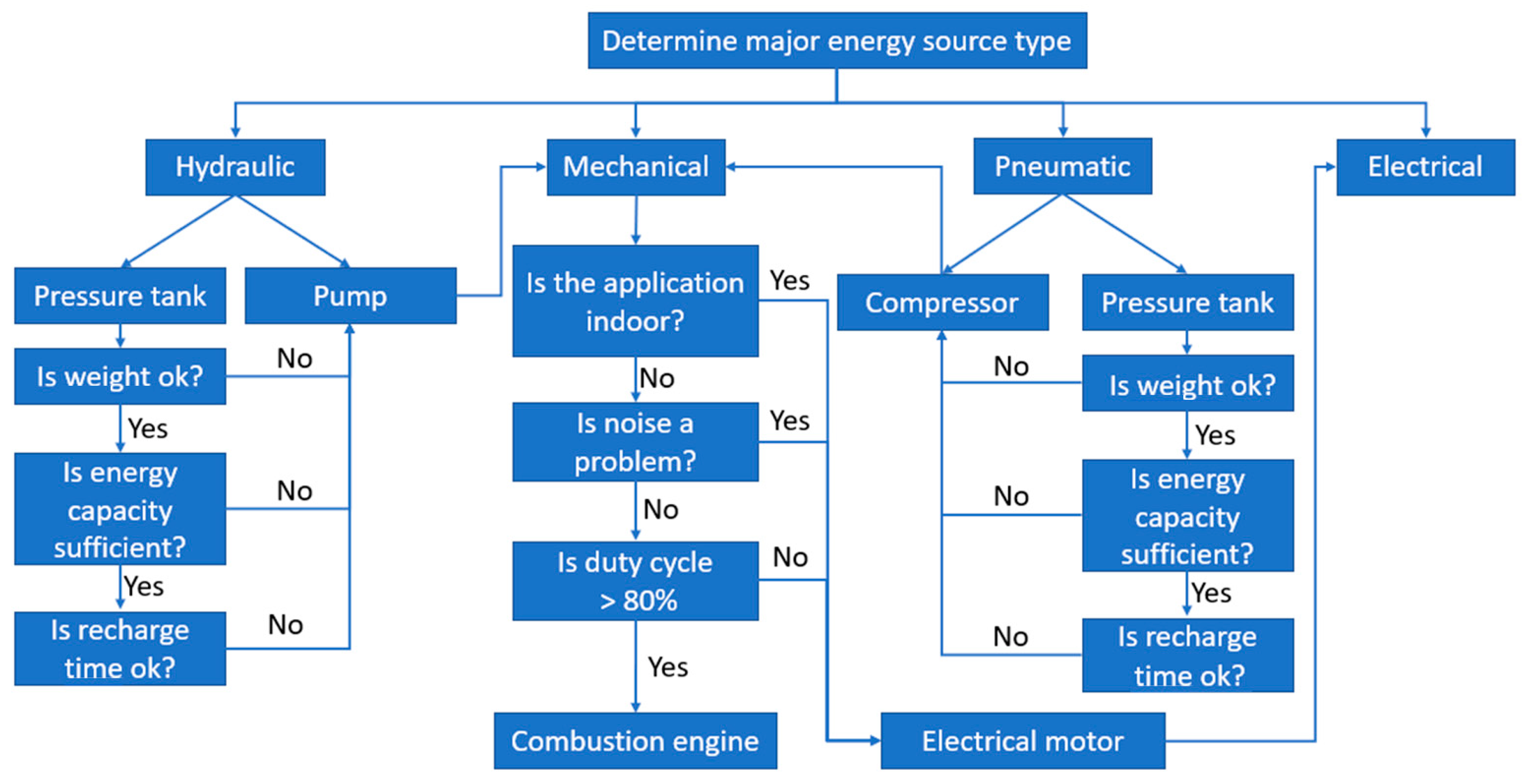
Selecting a power supply for a mobile robot begins with determining a list of components that require power. Those components should be then grouped by the type of power they require, namely, mechanical, electrical, pneumatic, and hydraulic. Within those groups, a second level of grouping is necessary—by the required power supply parameters. In the case of mechanical power, every mechanism requires some type of energy, either as rotary motion, when rpm would be the division criteria, or by motion trajectory for planar and 3D mechanisms. In electrical systems, voltage is the main factor used to group components. In pneumatic and hydraulic systems, pressure and medium are the two criteria; for example, separating water hydraulics from oil hydraulics as both require separate power sources.
Then, within each subgroup, typical and maximum power must be determined. A consecutive step is determining the main group that has the highest power demand. If there are two groups with similar power demands, then those two groups should be considered to be equivalently important. By knowing which source of power is the primary power, the selection of the power supply for this group can be made. In the case of mechanical power supply, various energy storage mechanisms can be selected, including electric motors or hydraulic motors and, therefore, an energy conversion option can be chosen. In the case of pneumatic/hydraulic systems, pressurized fluid can be stored in pressure tanks if the demand and weight of the tank are acceptable, thereby providing the required amount of energy for the application. Pumps and compressors can also be used to convert mechanical or electric energy to fluid power. When the main energy storage is determined for the most power-hungry system, the next-in-line system power supply should be selected. In this process it must be determined if the power supply should be based on an individual independent solution from the main power supply or energy conversion should be used from the main power supply. Converting energy from the main system requires additional components, which might be either expensive or bulky; it also requires increasing the main energy storage to support the second-ranked system power demand. Use of an individual supply can mean more maintenance but provides separation from noise and independence; for example, a control system powered by its own supply could work without interruption, even when the main power source fails or fully discharges, thereby enabling, for example, communication, reporting of problems, or graceful shutting down of other subsystems. The choice between energy conversion from the first to the next system or selection of an independent power source should proceed until the last subsystem. A graph illustrating power supply selection is presented in
Figure 1; for clarity, details of the process of selecting the electrical system power supply are presented separately in
Figure 2.
In the energy balance, in addition to energy consumers, suppliers should also be considered if they provide a substantial amount of energy. Such energy-harvesting systems comprise regenerative braking, which is part of the hardware and software design, solar panels, thermoelectric modules recycling waste heat, etc.
By knowing the general requirements for the prime power supplies, more detailed selection can take place. For electrical supplies, several options should be considered based on available battery technology and knowledge of regeneration systems that are part of the design. As batteries have limitations on the amount of charge they can take in charging or regenerative energy harvesting, if the pulses of energy are beyond the battery’s specification, intermediate energy storage such as supercapacitors should be considered. If regenerative energy is in mechanical form, mechanical means of energy storage should also be evaluated to determine the most efficient overall solution.
The efficiency and performance of the battery affects the entire power system of the mobile robot, and it should be noted that there can be more than one battery in a mobile robot, including those for memory backup. The main functions of the robot’s battery include providing power for the following:
Storing data files and backing them up (both for the status of the robot and documentation of its tasks: movement trajectories, photos, videos, classified objects, etc.), even after cessation of operation (movement, search of terrain or body of water);
Powering the robot’s actuation system (movement and, for example, moving arms or cameras);
Control of the robotic system, including wired and wireless interaction and communication devices, including program file storage.
A lack of power may prevent the robot from moving, but should not result in the loss of stored data, even due to battery exhaustion. Conversely, battery depletion may result in the need to recalibrate, program, or teach the robot. Methods for monitoring the robot and scheduling its maintenance (including preventive maintenance) are standard solutions in the Industry 4.0 paradigm (the so-called time/hourly backup battery renewal schedule). Additional safety features include the following:
An alarm or warning indicating low battery levels, in several places, including on the device used to remotely control the robot) and on the controller itself;
An indication of an inability to save data or errors indicating low battery levels;
A power reserve when the robot shuts down, allowing the battery to be replaced without losing any data.
5.2. Future of Mobile Robot Energy Sources for Power Systems
The current limitations of mobile robot batteries and their impact on mobile robot development are as follows:
The cost of higher capacity batteries, which practically limits mobile robots for light tasks;
Limited working speed, also due to the safety concerns of surrounding people and objects;
Requirements for the area of use (more weight usually means less maneuverability);
Specific charging time and frequency.
5.2.1. Directions for Further Research
Future research directions in the area of battery technology for mobile robots include the following:
Batteries based on seawater (Karlsruhe Institute of Technology, Germany) [
79,
80];
Iron-flow batteries (but larger) [
81,
82];
Silicon as the anode in a lithium-ion battery—organosilicon-based liquid solvents [
83,
84];
Magnesium metal batteries (twice the energy density than current solutions), e.g., zinc-manganese oxide battery [
85,
86];
Lithium-sulfur battery technology made of B4C-hemp, i.e., boron carbide made from hemp [
87,
88,
89];
Lithium-tungsten batteries [
90,
91];
Gold nanowire gel electrolyte batteries (gold nanowires reinforced with a manganese dioxide coating encapsulated in a Plexiglas-like gel electrolyte, which is reliable and fail-safe) [
92];
Batteries containing a collection of small independent self-organizing cells [
93].
Battery development also covers their charging and lifetime monitoring and recycling; these technologies also should be replaced by novel ones.
The biggest problem of clean and cheap renewable power sources is that they are dependent on environmental conditions, despite existing pumped hydro-storage systems, sand- or volcanic-rock-based systems, flow batteries, etc. Appropriate solutions must be provided for the future.
5.2.2. Limitations of Previous Studies
Limitations of previous studies are defined by the low quantity of open-source research and the secret details of technologies. Thus, the number of existing technologies can be higher, and in this way it is similar to the big pharma industry.
The discussion of the research presented in this paper and the current economic situation in Europe indicates that the current research is limited by the global crisis and material shortages. Thus, the technological possibilities are not fully exploited. Paradoxically, the time of war may cause another breakthrough due to the possible rapid development of flying drones, which have been commonly used during the war in Ukraine starting on 24 February 2022. The implications in the broad context show that progress is a necessity, taking into consideration the generation of novel solutions in the area of battery development. There are still many research gaps and a lack of knowledge to build useful datasets. Interdisciplinary research teams with robust big data on battery systems and materials could shed light on the actual performance of battery systems [
94,
95].
This article presents the state of knowledge and an analysis of the sources of power systems of mobile robots moving in various ways on the surface. There are also mobile robots that also move in other environments, e.g., in the air—UAVs (Unmanned Aerial Vehicles), or in the water—AUVs (Autonomous Underwater Vehicles). The issues of drive sources of UAVs are presented in a number of articles [
96,
97,
98,
99,
100,
101,
102,
103,
104]. Due to the environment’s need to overcome the force of gravity, these robots have special power requirements [
105,
106,
107,
108,
109,
110,
111].
6. Conclusions
In this paper, power systems based mainly on batteries from different materials for mobile robots were presented. Different energy sources were considered, and a detailed analysis of the electrical sources was performed. This can be summarized as follows:
Comparison of different types of batteries (lead-acid, AGM, Gel, NiMH, LiPo, LiFePO4) shows that the most versatile solution currently available, characterized by high specific energy and specific power, low self-discharge rate per month, and good safety, is LiFePO4 technology.
New types of batteries with excellent qualities are the subject of research (batteries based on seawater, iron-flow batteries, silicon as the anode in a lithium-ion battery, organosilicon-based liquid solvents, magnesium metal batteries, lithium-sulfur battery technology made of B4C-hemp, lithium-tungsten batteries, gold nanowire gel electrolyte batteries).
An important parameter of batteries in applications is energy efficiency, which depends both on battery chemistry and the drive system of the robot.
A summary of the bipedal walking robots and driving robots is presented with examples.
AMRs are a very important factor in the development of Industry 4.0. Distinct types of AMR are available: fetching, picking, or sorting. These robots with different structure require different batteries (voltages, current supply, and capacity) to function efficiently. Li-ion batteries are mainly used as the power source.
The use of Li-ion batteries containing a LiFePO4 cathode and a graphite anode is increasing. For AMR application, batteries from 12 to 96 V and capacities from 10 to 200 Ah are used. Individual (3.27 V) cells are combined in series/parallel connections to build such battery packs. The run time of robots is mostly targeting (∼8.4 h), which is more than 3 times than the charging time (∼2.7 h).
Modern batteries in applications have many benefits, including:
- ○
Higher operating voltage and higher capacity;
- ○
Longer operating time;
- ○
Shorter down time;
- ○
Longer cycle life.
Based on the review of power systems in the paper we propose:
- ○
An algorithm for selecting the main energy source for robot application in which we can consider the main source type (hydraulic, mechanical, pneumatic, electric);
- ○
An algorithm for selecting the electrical system power supply, which can help to find the optimal electrical source (NiMH, LiPo, LiFePO4, supercapacitors).
Current mobile robot battery solutions are still a trade-off between weight/size and capacity, making them the biggest limitation of robots. Progress in battery development is too slow, limiting the development of mobile robots themselves and their autonomy and range.
Considering the broader perspective, we need to see changes taking place in the perception of the importance of sustainability, environmental pollution, energy costs and the availability of fuels, components, and raw materials, including those based on AI-assisted optimization [
89,
90]. Intelligently managed, more efficient, more cost-effective, and less environmentally damaging powering of mobile robots will not only allow the further development of manufacturing, transport, and services, but will also contribute to the development of new business models, including in the area of public transport (subscription model, vehicle sharing), which will have important scientific and technical, but also economic and social, consequences
Further intensive research and implementation work is needed in the field discussed in this paper. In addition, the current global economic situation, including the energy crisis, may make the use of mobile robots too expensive and their expected market success will be postponed for many years, as may happen in the near future with the implementation of electric cars.


 ,
, 


