Article

Implications of Arch Warp Altitudes on an Ancient Masonry Bridge under Ground Movements

Department of Civil Engineering, Zonguldak Bulent Ecevit University, 67100 Zonguldak, Turkey
*
Author to whom correspondence should be addressed.
Appl. Sci. 2023, 13(13), 7395; https://doi.org/10.3390/app13137395
Submission received: 3 May 2023 / Revised: 20 May 2023 / Accepted: 22 May 2023 / Published: 22 June 2023
(This article belongs to the Special Issue Bridge Structural Analysis)

Abstract

:
Although only a few of the ancient masonry arch bridges (MABs) are in fairly good condition today, many ancient arch bridges are still in use. Over time, the condition of the masonry bridges declines and the safety requirements change. Therefore, it is important to examine these bridges under different influences. The strengthening of MABs is generally not essential. The major cause of damage to MABs is their insufficient width and height, and thus, it is not the safety but the usability that has restricted the life-time of the MABs. Therefore, in this investigation, the effect of the arch height on the static and dynamic behavior of a single-span MAB was investigated. For this aim, the Ancient Tokatlı Bridge, built in Karabük, Türkiye, was selected for investigation under near-fault (NF) and far-fault (FF) ground motions (GMs). To observe the altitude of the arch warp on the ancient MAB, first, the finite element model (FEM) was utilized, using ANSYS and SAP 2000. Furthermore, to constitute the arch warp’s influence on a MAB, the FEM was remodeled considering the different arch warps between 7.0 and 9.0 m. Moreover, GMs were applied to the FEM to investigate the effect of dynamic behavior. Under these GMs, stresses and strains (compression and tensile) were observed and compared with each other. Consequently, at the end of these investigations, it was observed that the maximum motions were reduced, while the height of the one-span MAB was increased under NF and FF GMs, and this was also true for the contrary situations. The compression stresses were not observed to be hazardous at the point of destruction, while the altitude of the one-span MAB increased.

1. Introduction

In the past, people have constructed bridges utilizing various approaches and systems, starting from the easiest methods to the later contemporary knowledge, and based on single studies. In these bridges, the arch method was extensively chosen, as presented in Figure 1. Arch bridges, frequently surveyed in Türkiye, were originally constructed in Anatolia, specifically using the method of the one-span MAB. In Türkiye, almost 1300 of these one-span MABs are in use. It is important to confirm the protection of these ancient bridges considering the dynamic changes in traffic, wind, and GMs, all of which involves finding the exact specifications of the dynamic features of these bridges [1,2,3,4]. For the construction of ancient masonry bridges, including various constructional parts such as quarry stonework, keystone, pavement, etc., it could be very important to study the influence of GMs. These implications could be important mainly for the characteristics of construction considering factors such as acceleration, velocity, motions, stress dispersion, etc. [5]. It is naturally predictable that resonance properties and spectral reactions are generally performed lengthwise with the construction altitude, specifically for conventional construction instead of complex construction [6,7].
For this reason, the seismic implications stated above still need to be further examined, for instance, for the construction of ancient masonry bridges. Additionally, acceleration, velocity, motions, stress dispersion, etc., as a result of the complex masonry construction, also become significant under the implications of soil–construction contact [9,10,11,12]. These ancient constructions, which have been utilized from the past to the present and have a history of thousands of years, have been damaged or destroyed via natural or human forces, e.g., GMs, wars, and fires, throughout history. The main bridges in the European rail network, in addition to the majority of bridges in the road structure, comprise these MAB constructions. Therefore, special attention needs to be paid to preserving the national road and rail networks [13]. Due to the importance of the ancient MAB constructions, there are several analytical and investigational research works based on ancient bridges in the literature [14,15,16,17]. Along with these investigations, Brencich and Sabia [18] examined Tanaro Bridge. In this investigation, the natural frequencies, mode shapes, and damping proportions of the 18-span masonry structure were designated with the help of dynamic tests. Diamanti et al. [19] implemented non-devastating, ground-penetrating radar (GPR) on MABs for the observation of ring departure. To confirm and update the analytical consequences, numerous laboratory investigations were presented. Another investigation was carried out by Ural et al. [20], who successfully implemented analytical models and dynamic experimental research via forming the concrete-filled steel Beichuan Bridge in FEM using ANSYS. Analytical forming methods were used to simulate the GPR tests. Then, the analytical models were updated with the laboratory test results. Sarhosis et al. [21] noticed the impact of the curvature angle on the load-bearing capability of a one-span stone MAB. Conde et al. [22] examined the impact of geometry on the destruction load approximation of an in-service mediaeval MAB. Sayın [23] presented linear and non-linear dynamic studies of the ancient Nadir Bridge. For this objective, the bridge was modeled with 3D FE, and then, the seismic reaction of the bridge was examined. Aydın and Özkaya [24], also examining the destruction loads of MABs, implemented an investigation calculating the performance of one-span MABs under certain loads via the static examination method. Altunışik et al. [25] offered a detailed examination of the valuation of the structural performance of ancient MABs in view of the altered arch warp. For this objective, a FEM of the bridge was established with special software to designate the structural performance. To prove the arch warp’s influence, the FEM was remodeled in view of the altered arch warps, between 2.86 and 3.76 m and 2.64 and 3.54 m for the first and second arches, with an increase of 0.10 m, respectively. It was realized that the arch warp had an impact on the constructional reaction of the ancient MABs. Breccolotti et al. [26] studied a border examination process for the quick valuation of the in-plane seismic ability of MABs, and parametric examination was performed via changing the rise/span proportion; the consequences were related to those found via FEM. Hamad [27] examined the stress/strain and strain energy concentration situations of the Dalal MAB in Mesopotamia. Furthermore, the constructional formation of ancient bridges made of natural stone has been consistently established, and the exact consequences were obtained via 3D FE. A common method for calculating the ring stone of the biggest ellipse-shaped arch of the Dalal Bridge was constructed on the basis of more relevant models of destruction. At the end of this study, Hamad [27] presented that amid all the proposed models, the most appropriate method is the maximum principal stress model, whose consequences provide the most accurate indication of the state of the construction. The other study was performed by Sokolović [28]. In this study, Sokolović [28] examined the longitudinal fractures in a one-span MAB to estimate its effect on the structure. For this purpose, Sokolović [28] performed FEM examinations of the bridge to determine the reasons of the longitudinal fractures. This study was a general investigation on a one-span MAB, observing how altered deterioration mechanisms, in combination, may cause the formation of fractures in MAB and consequently offers helpful procedures. The other study was performed by Demirel and Aldemir [29]. In this study, Demirel and Aldemir [29] proposed a hybrid method using a simple micro FEM on the basis of the principles of a limit examination method for the valuation of ground motion performance of these dry-joint masonry arches. In this study, the method was implemented for an antique dry-joint Roman MAB depending on important ground motion hazard. Consequently, it was examined whether the inadequate performance of the bridge was improved via retrofitting processes, for instance, reconstruction the wrecked spandrels, sidewalls, pavement, and the implementation of backfilling. Another study was performed by Bencardino et al. [30]. In that study, Bencardino et al. [30] performed a constructional examination of the existing railway bridge with masonry arches on the San Nicola-Avigliano Lucania line in the city of Potenza, Italy. For this aim, a non-linear non-adaptive static examination was performed for the valuation of the global ground motion performance of the bridge. At the end of this study, no consequences of the examination were observed considering risk factors on the basis of the existing codes. On the other hand, the suggested ground motion restoration solution proved to be effective and real, leading to the confirmation of the ground motion performance. Ou et al. [31] implemented another investigation. In that investigation, the combined finite-discrete element method (FDEM) was chosen to simulate the destruction performance of historic masonry traditions to support differential descent. Furthermore, in this study, an original and operational tool was proposed to evaluate the potential destruction or destruction method of historic masonry traditions under numerous variance descent scenarios, which is extremely helpful to defend these precious historic culture constructions in contrast to descent possibilities and also to improve the literature on FDEM masonry applications. At the end of this study, it was found that the deformation ability of masonry constructions is more enhanced than that of the monolithic counterpart constructed with the same configuration. Addessi et al. [32] examined the non-linear dynamic reaction of the MAB ‘Ponte delle Torri’ in Spoleto, targeted at evaluating the ground motion performance of the construction and estimating the taking place damaging mechanisms. For this purpose, a 3D-FE macro-mechanical process applied in the FE program FEAP was implemented to model the bridge. At the end of this investigation, a serious valuation of the bridge provision considering the arrangement of accelerograms and the one record was completed, and the relations among the wrecked construction dynamic provision and the signal characteristic were emphasized. Another study by Savini et al. [33] aimed to demonstrate the effectiveness of stratigraphic examination to evaluate the progress of the examination and constructional description of MABs. At the end of this study, Savini et al. [33] offered that the recommended technique increases the information and facilitates the drafting of archives regarding the state of health of MABs. The consequences demonstrate how interdisciplinary methods suggestively increase and improve the information about infrastructural cultural heritage. Accornero and Lacidogna [34] examined the elastic-fracture-plastic transitions for three monumental MABs with changed shallowness and slenderness proportions. At the end of this study, it was determined that this practice was important because it provided an accurate and effective valuation of the full-service life of MABs and, more generally, may be appropriate for many historic masonry constructions that still have strategic or culture significance in infrastructure systems. He et al. [35] investigated the dynamic assignment and FEM of a butterfly-arch stress-ribbon pedestrian bridge. In this study, an attempt was made to evaluate the optimum FE modeling options to obtain a satisfactory agreement among the model estimation and the experimental records. The developed FE model might be used as a basis for long-term monitoring of the bridge. It is also emphasized that it can be a guide for practitioners and academics all over the world for modeling and analyzing such structures. Another investigation was performed by Milani and Lourenço [36]. In this investigation, Milani and Lourenço [36] investigated the static non-linear performance of MABs using a 3D FE numerical code. At the end of the investigation, a clear advantage of using 3D analyses for MABs was observed. As mentioned above, only a few studies till date have evaluated the seismical valuation of ancient MAB [37,38,39,40,41,42]. The geometric properties, proportions, and forms of each constructional component significantly affect the constructional performance of ancient MABs. In the literature, some constructional analyses have been carried out to examine the influences of geometry on the constructional performance of MABs. Nonetheless, there are no seismic examinations for assessing the geometry influence, especially for MABs [42,43,44,45]. Thus, in this investigation, we aimed to examine the performance of ancient MABs under altered arch warp considering the near and FF GMs via the FEM approach and to prove the performance predicting ability. Accordingly, a one span-ancient MAB built in the Karabuk, TÜRKIYE was chosen and examined. First, the characteristics and geometrical properties of the working bridge are briefly given, and then, the development of the first FEMs is defined, along with the initial estimates of the bridge properties. A detailed discussion of the one span-ancient MAB is given in the subsequent subdivisions.

2. Explanation of the One Span MAB

The one span-ancient MAB is in Karabük. The one-span ancient MAB is on a watercourse in the east–west axis. According to the information in literature, the one span-ancient MAB may have been constructed in the 18th century [46]. In the one-span ancient MAB, a pulley-shaped arch with smooth thin stones and one-eyed ancient MAB stones were used, and the Tempan walls and arch core were constructed using the small rubble stone method. As the original stonework is found in the lower parts of the Tempan wall, it was realized that it has been repaired with stones of altered dimensions on the upper side. The one span-ancient MAB is about 47.26 m long and 4.10 m wide. The altitude from the one-span ancient MAB to the river is 30.70 m. The overall structure of the one span-ancient MAB is presented in Figure 2.

3. Modeling

In this section of the investigation, the FEM of the one span-ancient MAB was built to examine the performance of the MAB under varying arch heights, and analyses were implemented under NF and FF GMs via the FEM. For that purpose, first of all, a 3D non-linear FEM was created via ANSYS [47]. Then, ANSYS solving of the model was performed via different NF and FF GMs. Then, structural analyses of the old MAB under the modified arch curvature were completed to inspect the performance of the bridge. In addition, the SAP 2000 [48] model was established to determine the mode shapes and natural frequencies of the one span-ancient arch bridge. Then, the results from non-linear FEMs in ANSYS were compared. The information of the FEM is described in the subsequent subsections.

3.1. Component Forms

In the formation of the one span-ancient arch bridge, the rating of freedom was obtained in accordance with the component form to model the constructional performance under various loading conditions. Furthermore, the construction is separated into small and simple components joined at intersecting nodes. The one span-ancient MAB was modeled via tetrahedron components. The peculiarity of this component is that it is of a high order with 10 nodes. This component has a quadratic displacement performance and is well matched for demonstrating irregular meshes and interaction faces [49]. In view of that, such a component is well suited for forming the face interaction amid the constituents of the one span-ancient MAB and the asymmetrical geometry of the FEM. Each node of the component has three ratings of freedom, which is the translations at the x, y, and z nodes. The interaction algorithm of the FEM involves the description of the interaction faces. Information of the interaction face formation is provided in the subsequent subdivisions.

3.2. Interaction Forming

The investigation of the tweening produced via solid forms touching each other at one or more points is described as interaction mechanics [49]. In this investigation, it is described as a function of the degree of departure of the interaction faces among the one span-ancient MAB and its constituents, and as a face-to-face interaction form where the interaction area can vary. This form of interaction is recognized while the face of one object comes into interaction with the face of an additional object. It is also often expended for arbitrary objects with large interaction areas [50,51]. To define a pair of interaction faces, one of the faces is chosen as the interaction component and the other as the target component. Both components must have the similar specific features, for instance, the amount of nodes and their positions [50]. For the interaction interfaces of the Ancient Bridge, the CONTA-174 part and a matching TARGE-170 part are described to represent the interaction and departure between the two faces [52]. Consequently, bonded interaction is elected among the one span-ancient MAB and their constituents.

3.3. Meshing

The mesh dimension and form expended are essential to precisely predict stress and/or strain values in a FEM. Therefore, to provide the suitable mesh concentration in the FEM of the Ancient Bridge, the mesh dimensions were changed and the investigations were repeated for each case. Accordingly, four mesh options in the FEM were tested and compared. The properties of the other meshing selections are presented in Figure 3. A larger quantity of nodes in a FEM resulted in an extremely long calculation period. Consequently, the Tetrahedrons meshing choice is elected for the reason that the found mesh has improved measurement dispersion across the FEM and smaller number of nodes. Then, the chosen meshing choice is tested via various mesh dimensions, starting with 250 mm (the dimension along the length is 250 mm, while the one perpendicular to the length is adjusted according to the width) and reducing the mesh dimension until the consequences become stable. The biggest mesh dimension giving stable consequences is then elected for the FEM. The maximum strain worth in the one span-ancient MAB remains approximately continuous for 50 mm and 25 mm mesh dimensions (0.012443 and 0.012466, respectively). Consequently, the mesh dimensions are manually calculated, obtained to be 25 mm for the interaction areas and 50 mm for the rest of the model.

3.4. Material Model and Border Situations
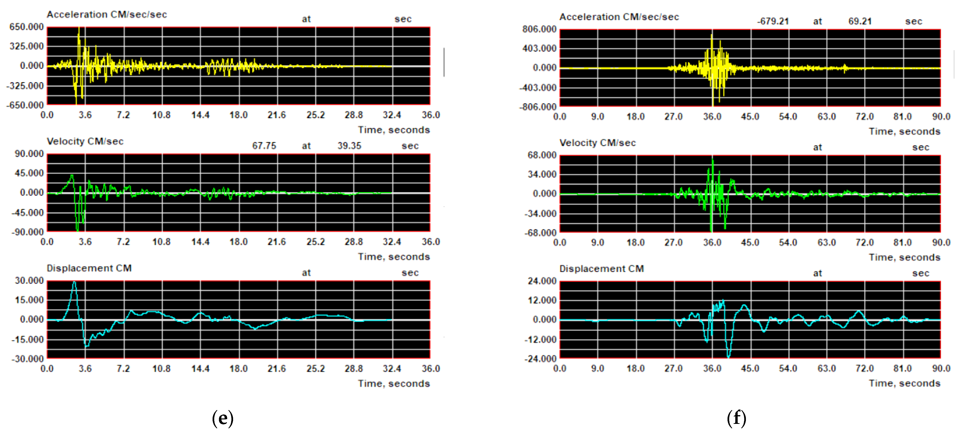
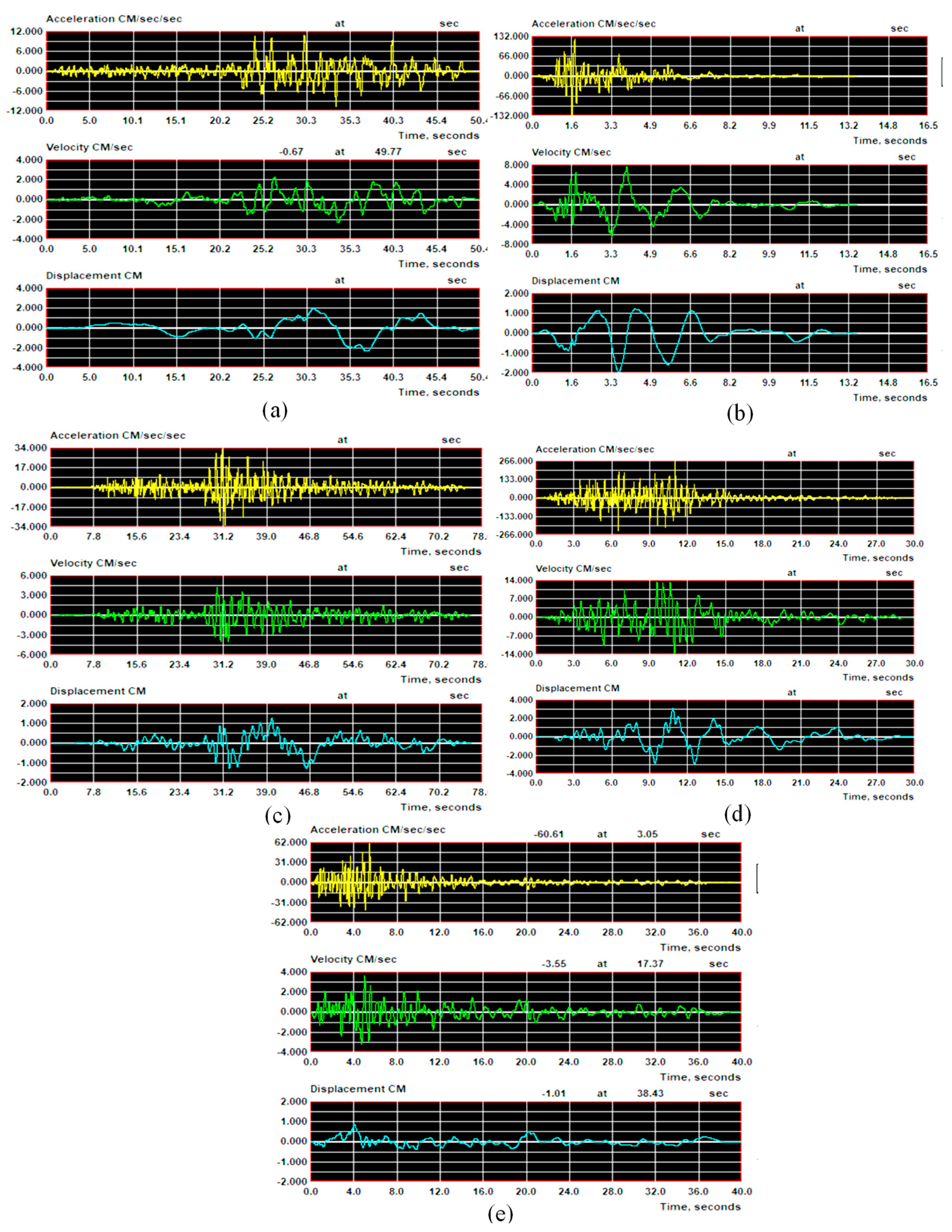
To obtain correct examination consequences, real material properties are needed in the Non-Linear FEM of the Ancient Bridge. The material properties expended in the analyses are presented in Table 1 [1]. The Concrete Damage Plasticity (CDP) model is implemented to simulate the non-linear behavior of the wall [53]. Though originally established to define the non-linear performance of concrete [54,55], the usage of such a model for masonry is generally accepted in studies after the key restrictions are properly adapted. The CDP model is a damage model on the basis of the continuous plasticity, permitting changed tensile and compressive strength as in the wall, with changed damage parameters in stress and compression [53]. On the FE examination, the exact description of the border conditions along with the material model is of great importance. This also greatly affects performance depending on the build. Border conditions for all bridge supports and both sidewalls are described via fixing translational and rotational rating of freedom. In the model, the Modulus of elasticity, Density and Poisson proportion are defined as E, ρ and γ, respectively.

4. NF and FF GMs

In this investigation, GMs close to the fault and far from the fault are discussed as a result of their distinctive, devastating velocity impact features. Table 2 lists the NF and FF GMs expended in this investigation. This set of ground motion records expended in the examination take account of ground motion parameters in a variety of ways, as in Figure 4 and Figure 5. Nonetheless, a recent investigation by Makris and Black [52] suggested that peak ground acceleration (Ap) is a more essential restriction to describe the NF GMs. Therefore, both Ap and Vp that are contained within the Ap/Vp proportion of GMs are chosen to describe the NF GMs reflected in this investigation. The Ap/Vp proportion is also characteristic of the main frequency and energy substance of the GMs [52]. Low Ap/Vp proportions indicate GMs with intense, long-period acceleration pulses, as great Ap/Vp proportions attend GMs having short-duration acceleration pulses. These sets include a group of 11 GMs, as presented in Table 2.

5. Analyses Consequences

In this phase of the investigation, the structural performance of a one-span ancient MAB was examined in view of the altered arch warp under NF and FF GMs. For this objective, as mentioned above, NF and FF GMs are reflected as a result of their unusual, damaging velocity pulse features. The mode characters are very significant in response to the general efficiency of constructions. For this reason, before the dynamic examination, FEM of the one span-ancient MAB was first performed to gain the mode characters and additional consequences, by using SAP 2000, as presented in Figure 6. Considering the design of the model, the self-weight examination is achieved under its self-weight. To define the mode characters, modal examination was performed in SAP 2000, and the tweening of the first 10 Modes of One span-ancient MAB is recognized and presented in Figure 7. The construction of the first 10 Mode periods is presented in Figure 7. Moreover, self-weight and movable load as well as vehicle loads are taken into consideration throughout the static examination, as presented in Figure 8. The maximum tweening, elastic stresses, and stress values found on the examination are presented in Figure 8. To determine the arch warp influence on a MAB, the FEM is remodeled in view of the altered arch warp using 7.0–9.0 m with an increase of 1.0 m, individually, as presented in Figure 9. Then, a self-weight examination is performed under its self-weight, as presented in Figure 10. As the dynamic conduct of a one-span ancient MAB is examined in view of an altered arch warp under NF and FF GMs, stress and motions graphs were observed, as presented in Figure 11. Several models of the destruction mechanism were observed. In view of the 3D model and the characteristic types of stone constructions, it was suggested that the tensor of the stresses was owing to the displacement contained by the ring stone. The maximum principal strain model is proposed for the brittle fracture of supplies, as also recognized in the St. Venant’s model. According to the St. Venant’s model, the limiting state of the supply is attained while the maximum tensile strain, εmax = ε1, approaches with a specific constant limit value equivalent to the consistent pressure, ε0, at rupture. This correlation is assumed as follows;
ε m a x = ε 1 = 1 E σ 1 γ σ 2 + σ 3 = ε 0
To obtain a safe design, the maximum principal strain must be smaller than the permissible strain as follows:
ε m a x = ε 1 = 1 E σ 1 γ σ 2 + σ 3 y i e l d i n g   s t r a i n f a c t o r   o f   s a f e t y = σ y E . n
This rule is still unclear considering the findings in various resources; nonetheless, in some situations, it offers an eligible verification of the destruction mode of the resources, for instance, while longitudinal fractural fractures take place in usual stones under compression. A one-span ancient MAB was also considered in the maximum distortional strain energy density model. The total strain for the triaxial situation might be considered in the following equation:
T o t a l   S t r a i n   E n e r g y   p e r   u n i t   v o l u m e = 1 2 σ 1 ε 1 + 1 2 σ 2 ε 2 + 1 2 σ 3 ε 3
In which,
ε 1 = 1 E σ 1 γ σ 2 + σ 3
ε 2 = 1 E σ 2 γ σ 1 + σ 3
ε 3 = 1 E σ 3 γ σ 1 + σ 2
As a consequence, the final calculation for energy is assumed by
S t r a i n   E n e r g y   D e n s i t y = 1 2 E σ 1 2 + σ 2 2 + σ 3 2 2 . γ σ 1 σ 2 + σ 2 σ 3 + σ 1 σ 3
Assuming the one-span ancient MAB is steady and unharmed considering earth’s gravity, it might be expected that there will be no harm to the one-span ancient MAB when the drawing stress was increased up to 2.20 MPa. This drawing stress was found to be steady with the traction resistance/pressure resistance proportions (1/20–1/10), as suggested by Pela et al. [12] for masonry constructions and which might be expended as a control to evaluate the possible harm. Consequently, as stated above, at this point of the examination, the traction resistance/pressure resistance proportion is measured as 1/20 or 5% and the possible harm is estimated. Thus, it is expected that the drawing stress values of bigger than 1/20 or 5% might be concentrated via the harmful constructional strength. In addition, as presented in Figure 11, the drawing stress was improved via the influence of the NF earthquake and is essential particularly along the large belt while the altitude of the arch warp reduced. In view of the NF GMs loading that was implemented for the estimations, the drawing stress increased up to 0.60 MPa under static loading on the one span-ancient MAB, with an improvement up to 2.20 MPa as a result of the NF earthquake implications and exceeded the traction resistance of the one span-ancient MAB, which is recognized to be 1 MPa; in contrast, the altitude of the arch warp was reduced. When the FEM is examined in detail, the drawing stress at several nodes is bigger than 1 MPa. These results specified that destruction might be produced via drawing stress under NF GMs, particularly while the altitude of the arch warps reduced. As the pressure stresses under the influence of NF GMs are quite low compared to the pressure resistance of the Ancient Bridge, no destruction was estimated as a result of pressure. Figure 11 shows that the drawing stress on the one span-ancient MAB faced under NF earthquake implications is more than 1 MPa and that may be hazardous considering destruction. As can be seen from Figure 11, the top, bottom, and side of the MAB might be critical for destruction. These results are reliable considering the consequences of the influence of their particular mass and seismic activity weight. In the subsequent phases, fractures that might follow with the improvement in the load influence might be estimated to start beginning from these sections and owing to the destruction mechanism. The consequences of dynamics studies are presented in Table 3, Table 4 and Table 5. Furthermore, in Figure 12, the results are also given.

6. Results

In this investigation, a particular examination about the valuation of structural performance of a one-span ancient MAB in view of the altered arch warp under NF and FF GMs has been suggested. For this objective, FEM of the one-span ancient MAB was performed under numerous NF and FF GMs via the program ANSYS and SAP 2000. The following observations were found:
  • The results of the analyses made within the scope of the study show that under standard gravity, the collapse of the MAB is not caused by the stress and displacement values.
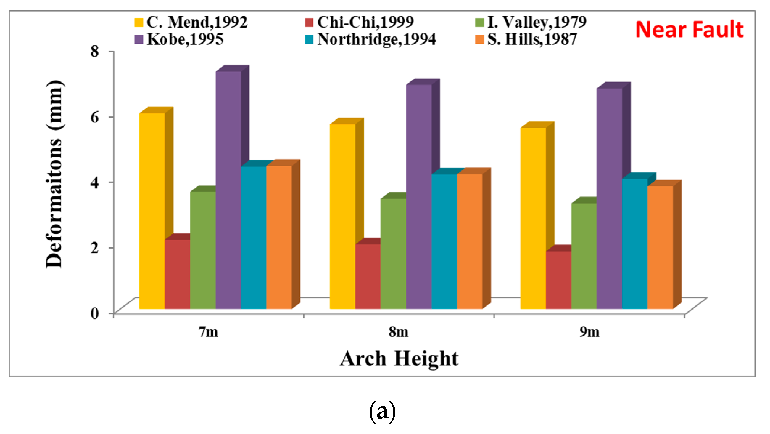
  • The consequences indicate a clear advantage of using 3D investigations for MABs considering the cases studied. The consequences of the analyses demonstrate the most critical sections of the MABs as the altitude of the arch warps decreases. Furthermore, it was detected that the maximum motions reduced while the altitude of the one-span MAB increases under NF and FF GMs and vice versa.
  • It was observed that the arches that carry the main structure of the MABs are the divisions that are essential for examination considering their seismic performance.
  • While the altitude of the one-span MAB rises specifically under NF GMs, it was noticed that the obtained stress reached the allowable masonry traction resistance. Furthermore, the evidence of dynamic investigations showed that the most critical sections of the MAB are the sub-sections of the MAB, specifically on the higher side of the large belt, posing a hazard for destruction. The maximum principal stress values demonstrated a decrease as the MAB height increases, decreasing from 2.27 MPa to 0.881 MPa.
  • Furthermore, deformation values of MAB showed a reduction as the MAB height increased, decreasing from 5.96 mm to 5.52 mm. Dangerous (large) relation displacement stages were not determined along the MAB altitude.
  • The compression stresses are well under the masonry pressure resistance and are not reflected to be hazardous considering the point of destruction while the altitude of the one-span MAB rises. Moreover, for the one-span MAB, the potential destruction as a result of motions was established to be critical when the altitudes of the one-span MAB reduced. Nevertheless, there is no movement at the degree that would lead to destruction to the sections of the one-span MAB that were left behind.
  • As a result of the modeling approach chosen, it was observed that behavior (damage, etc.) takes place in the sections where stresses are concentrated in the elements. Furthermore, although stress/strain values increase in small amounts as a result of NF and FF GMs, significant decreases in fatigue life occur when the height of the arch warp increases.
  • Future studies with field observation as well as analytical investigations are needed to contribute to the literature. The current investigated the effect of height, thereby contributing to the basis of other investigations that should be performed in future.

Author Contributions

Conceptualization, M.K.; methodology, M.K. and M.Y.; software, M.Y. validation, M.K. and M.Y.; formal analysis, M.Y.; investigation, M.K. and M.Y.; resources, M.K.; data curation, M.K. and M.Y.; writing—original draft preparation, M.K.; writing—review and editing, M.K.; visualization, M.K. and M.Y.; supervision, M.K.; project administration, M.K.; funding acquisition, M.K. All authors have read and agreed to the published version of the manuscript.

Funding

This research received no external funding.

Institutional Review Board Statement

Not applicable.

Informed Consent Statement

Not applicable.

Data Availability Statement

The study did not report any data.

Conflicts of Interest

The authors declare no conflict of interest.

References

  1. Sevim, B.; Bayraktar, A.; Altunisik, A.C.; Atamturktur, S.; Birinci, F. Assessment of nonlinear seismic performance of a restored historical arch bridge using ambient vibrations. Nonlin. Dyn. 2011, 63, 755–770. [Google Scholar] [CrossRef]
  2. Koksal, H.O.; Doran, B.; Kuruscu, A.O.; Kocak, A. Elastoplastic Finite Element Analysis of Masonry Shear Walls. KSCE J. Civ. Eng. 2015, 20, 784–791. [Google Scholar] [CrossRef]
  3. Cakir, F.; Seker, B.S.; Durmus, A.; Dogangun, A.; Uysal, H. Seismic assessment of a historical masonry mosque by experimental tests and finite element analyses. KSCE J. Civ. Eng. KSCE 2015, 19, 158–164. [Google Scholar] [CrossRef]
  4. Sözen, Ş.; Çavuş, M. Assessment of the Seismic Performance of a Historical Building Reinforced with Steel Buttress. KSCE J. Civ. Eng. 2019, 23, 3113–3121. [Google Scholar] [CrossRef]
  5. Güllü, H.; Karabekmez, M. Gaziantep Kurtuluş Camisinin Deprem Davranışının İncelenmesi. DÜMF Mühendislik Derg. 2016, 7, 455–470. [Google Scholar]
  6. Arnold, C.; Reitherman, R. Building Configuration and Seismic Design; Wiley: New York, NY, USA, 1982. [Google Scholar]
  7. Kramer, S.L. Geotechnical Earthquake Engineering; Prentice Hall: Hoboken, NJ, USA, 1996. [Google Scholar]
  8. URL-1. Available online: https://pixabay.com/tr/photos/mostar-köprü-seyahat-bosna-1155672/ (accessed on 29 April 2019).
  9. Raychowdhury, R. Effect of soil parameter uncertainty on seismic demand of low-rise steel buildings on dense silty sand. Soil Dyn. Earthq. Eng. 2009, 29, 1367–1378. [Google Scholar] [CrossRef]
  10. Luco, J.E.; Lanzi, A. Approximate soil-structure interaction analysis by a perturbation approach: The case of stiff soils. Soil. Dyn. Earthq. Eng. 2013, 51, 97–110. [Google Scholar] [CrossRef]
  11. Emre, Ö.; Duman, T.Y.; Olgun, S.; Elmacı, H.; Özalp, S. Active Fault Map of Turkey; General Directorate of Mineral Research and Exploration: Ankara, Turkey, 2012. [Google Scholar] [CrossRef]
  12. Mazza, F.; Labernarda, R. Structural and non-structural intensity measures for the assessment of base-isolated structures subjected to pulse-like near-fault earthquakes. Soil. Dyn. Earthq. Eng. 2017, 96, 115–127. [Google Scholar] [CrossRef]
  13. Pelà, L.; Aprile, A.; Benedetti, A. Seismic assessment of masonry arch bridges. Eng. Struct. 2009, 31, 1777–1788. [Google Scholar] [CrossRef]
  14. Page, J. Masonry Arch Bridges—A State of the Art Review; HMSO: London, UK, 1993. [Google Scholar]
  15. Armstrong, D.M.; Sibbald, A.; Fairfield, C.A.; Forde, M.C. Modal analysis for masonry arch bridge spandrel wall separation identification. NDT E Int. 1995, 28, 377–386. [Google Scholar] [CrossRef]
  16. Bensalem, A.; Fairfield, C.A.; Sibbald, A. Non-destructive evaluation of the dynamic response of a brickwork arch. ICE J. Struct. Build. 1997, 122, 69–82. [Google Scholar] [CrossRef]
  17. Bensalem, A.; Fairfield, C.A.; Sibbald, A. Damping effects on the NDT of soil backfilled arch bridges. J. Br. Inst. NDT 1998, 40, 107–116. [Google Scholar]
  18. Brencich, A.; Sabia, D. Experimental identification of a multi-span masonry bridge: The Tanaro Bridge. Constr. Build. Mater. 2008, 22, 2087–2099. [Google Scholar] [CrossRef]
  19. Diamanti, N.; Giannopoulos, A.; Forde, M.C. Numerical modelling and experimental verification of GPR to investigate ring separation in brick masonry arch bridges. NDT E Int. 2008, 41, 354–363. [Google Scholar] [CrossRef]
  20. Ural, A.; Oruç, S.; Doğangün, A.; Tuluk, Ö.İ. Turkish historical arch bridges and their deteriorations and failures. Eng. Fail. Anal. 2008, 15, 43–53. [Google Scholar] [CrossRef]
  21. Sarhosis, V.; Oliveira, D.V.; Lemos, J.V.; Lourenço, P.B. The effect of skew angle on the mechanical behaviour of masonry arches. Mech. Res. Commun. 2014, 61, 53–59. [Google Scholar] [CrossRef] [Green Version]
  22. Conde, B.; Díaz-Vilariño, L.; Lagüela, S.; Arias, P. Structural analysis of Monforte de Lemos masonry arch bridge considering the influence of the geometry of the arches and fill material on the collapse load estimation. Construct. Build. Mater. 2016, 120, 630–642. [Google Scholar] [CrossRef]
  23. Sayın, E. Nonlinear seismic response of a masonry arch bridge. Earthq. Struct. 2016, 10, 483–494. [Google Scholar] [CrossRef]
  24. Aydin, A.C.; Özkaya, S.G. The finite element analysis of collapse loads of single-spanned historic masonry arch bridges (Ordu, Sarpdere Bridge). Eng. Fail. Anal. 2018, 84, 131–138. [Google Scholar] [CrossRef]
  25. Altunışık, A.C.; Kanbur, B.; Genç, A.F.; Kalkan, E. Structural response of historical masonry arch bridges under different arch curvature considering soil-structure interaction. Geomech. Eng. 2019, 18, 141–151. [Google Scholar] [CrossRef]
  26. Breccolottia, M.; Severinib, L.; Cavalagli, N.; Bonfiglic, F.M.; Gusellad, V. Rapid evaluation of in-plane seismic capacity of masonry arch bridges through limit analysis. Earthq. Struct. 2018, 15, 541–553. [Google Scholar] [CrossRef]
  27. Hamad, F.S. Ancient Mesopotamian Stone Bridge: Numerical Modeling and Structural Assessment. Shock. Vib. 2022, 2022, 4255354. [Google Scholar] [CrossRef]
  28. Sokolović, N.M.; Petrović, M.; Kontić, A.; Koprivica, S.; Šekularac, N. Inspection and Assessment of Masonry Arch Bridges: Ivanjica Case Study. Sustainability 2021, 13, 13363. [Google Scholar] [CrossRef]
  29. Demirel, I.O.; Aldemir, A. Simplified Approach for Seismic Performance Assessment of Dry-Joint Masonry Arch Bridges. Buildings 2021, 11, 313. [Google Scholar] [CrossRef]
  30. Bencardino, F.; Curto, R.; Scavelli, V. Inspection and Structural Rehabilitation of an Existing Masonry Arch Railway Bridge. Appl. Sci. 2023, 13, 2973. [Google Scholar] [CrossRef]
  31. Ou, W.; Chen, X.; Chan, A.; Cheng, Y.; Wang, H. FDEM Simulation on the Failure Behavior of Historic Masonry Heritages Subjected to Differential Settlement. Buildings 2022, 12, 1592. [Google Scholar] [CrossRef]
  32. Addessi, D.; Gatta, C.; Nocera, M.; Liberatore, D. Nonlinear Dynamic Analysis of a Masonry Arch Bridge Accounting for Damage Evolution. Geosciences 2021, 11, 343. [Google Scholar] [CrossRef]
  33. Savini, F.; Rainieri, C.; Fabbrocino, G.; Trizio, I. Applications of Stratigraphic Analysis to Enhance the Inspection and Structural Characterization of Historic Bridges. Infrastructures 2021, 6, 7. [Google Scholar] [CrossRef]
  34. Accornero, F.; Lacidogna, G. Safety Assessment of Masonry Arch Bridges Considering the Fracturing Benefit. Appl. Sci. 2020, 10, 3490. [Google Scholar] [CrossRef]
  35. He, L.; Castoro, C.; Aloisio, A.; Zhang, Z.; Marano, G.C.; Gregori, A.; Deng, C.; Briseghella, B. Dynamic assessment, FE modelling and parametric updating of a butterfly-arch stress-ribbon pedestrian bridge. Struct. Infrastruct. Eng. 2022, 18, 1064–1075. [Google Scholar] [CrossRef]
  36. Milani, G.; Lourenço, P. B 3D non-linear behavior of masonry arch bridges. Comput. Struct. 2012, 110–111, 133–150. [Google Scholar] [CrossRef] [Green Version]
  37. Dogangun, A. and Sezen, H. Seismic vulnerability and preservation of historical masonry monumental structures. Earthq. Struct. 2016, 3, 83–95. [Google Scholar] [CrossRef] [Green Version]
  38. Muvafık, M. Field investigation and seismic analysis of a historical brick masonry minaret damaged during the Van earthquakes in 2011. Earthq. Struct. 2014, 6, 457–472. [Google Scholar] [CrossRef]
  39. Cakir, F.; Seker, B.S. Structural performance of renovated masonry low bridge in Amasya, Turkey. Earthq. Struct. 2015, 8, 1387–1406. [Google Scholar] [CrossRef]
  40. Preciado, A.; Bartoli, G.; Budelmann, H. Fundamental aspects on the seismic vulnerability of ancient masonry towers and retrofitting techniques. Earthq. Struct. 2015, 99, 339–352. [Google Scholar] [CrossRef] [Green Version]
  41. Basaran, H.; Demir, A.; Ercan, E.; Nohutçu, H.; Hökelekli, E.; Kozanoğlu, C. Investigation of seismic safety of a masonry minaret using its dynamic characteristics. Earthq. Struct. 2016, 10, 523–538. [Google Scholar] [CrossRef]
  42. Cakir, F.; Ergen, Y.B.; Uysal, H.; Dogangun, A. Influence of modified intended use on the seismic behavior of historical himis structures. Earthq. Struct. 2016, 10, 893–911. [Google Scholar] [CrossRef]
  43. Chung, Y.S.; Park, C.K.; Lee, D.H. Seismic performance of RC bridge piers subjected to moderate earthquakes. Struct. Eng. Mech. Int. J. 2006, 24, 429–446. [Google Scholar] [CrossRef]
  44. Onat, O. Fundamental vibration frequency prediction of historical masonry bridges. Struct. Eng. Mech. Int. J. 2019, 69, 155–162. [Google Scholar]
  45. Karalar, M.; Mustafa, Y. Effect of near-fault earthquakes on a historical masonry arch bridge (KonjicBridge). Earthq. Struct. 2021, 21, 125–136. [Google Scholar] [CrossRef]
  46. Emek, S. Karabük Safranbolu Tarihi Aşağı Tokatlı Köprüsü Röleve Restitüsyon Restorasyon Raporu; Karayolları Genel Müdürlüğü 15; Bölge Müdürlüğü: Karabük, Turkey, 2012; pp. 8–60. [Google Scholar]
  47. ANSYS. ANSYS User’s Manual Revision. 5.5; ANSYS Inc.: Canonsburg, PA, USA, 1998. [Google Scholar]
  48. SAP2000, Version 7.0. Integrated Finite Elements Analysis and Design of Structures. Computers and Structures, Inc.: Berkeley, CA, USA, 2008.
  49. Kamil, J.A.; Khan, I.A.; Nath, Y. Numerical and Experimental Dynamic Contact of Rotating Spur Gear. Mod. Appl. Sci. 2011, 5, 254–263. [Google Scholar] [CrossRef] [Green Version]
  50. Kadhim, M.M.A. Factors effect on the effective length in a double strap joint between steel plates and CFRP. Int. J. Adv. Appl. Sci. 2012, 1, 11–18. [Google Scholar]
  51. Makris, N.; Chang, S. Effect of Damping Mechanisms on the Response of Seismically Isolated Structures; PEER-98/06; Pacific Earthquake Engineering Research Center: Berkeley, CA, USA, 1998. [Google Scholar]
  52. Makris, N.; Black, J.C. Evaluation of peak ground velocity as a “Good” intensity measure for near-source ground motions. J. Eng. Mech. 2004, 130, 1032–1044. [Google Scholar] [CrossRef]
  53. Nemutlu, Ö.F.; Güzel, I.; Balun, B.; Öztürk, M.; Sarı, A. Nonlinear Seismic Assessment of Historical Masonry Karaz Bridge Under Different Ground Motion Records. Bitlis Eren Üniversitesi Bilim. Derg. 2023, 12, 247–260. [Google Scholar] [CrossRef]
  54. Lee, J.; Fenves, G.L. Plastic-Damage Model for Cyclic Loading of Concrete Structures. J. Eng. Mech. 1998, 124, 892–900. [Google Scholar] [CrossRef]
  55. Lubliner, J.; Oliver, J.; Oller, S.; Onate, E. A Plastic Damage Model for Concrete. Int. J. Solids Struct. 1989, 25, 299–326. [Google Scholar] [CrossRef]
Figure 1. An example of an Ancient Masonry Monstar Bridge [8].
Applsci 13 07395 g001
Figure 2. Structure of the historic Tokatli Bridge [46].
Applsci 13 07395 g002
Figure 3. Information of nodes and components for altered mesh form.
Applsci 13 07395 g003
Figure 4. NF, (a) GM#1, (b) GM#2, (c) GM#3, (d) GM#4, (e) GM#5, (f) GM#6.
Applsci 13 07395 g004aApplsci 13 07395 g004b
Figure 5. FF (a) GM#7, (b) GM#8, (c) GM#9, (d) GM#10, (e) GM#11.
Applsci 13 07395 g005
Figure 6. Modeling of the one span-ancient MAB in SAP 2000 (a) no deformed shape, (b) deformed shape.
Applsci 13 07395 g006
Figure 7. The period values of free vibration modes of MAB.
Applsci 13 07395 g007
Figure 8. Ancient Bridge, Static Examination in SAP 2000, (a) Total Tweening, (b) Max. Principal Elastic Strain, (c) Max. Principal Stress.
Applsci 13 07395 g008
Figure 9. 3D FEM of the MAB for, (a) 7 m, (b) 8 m, (c) 9 m.
Applsci 13 07395 g009
Figure 10. Ancient Bridge, Static Examination in ANSYS for Total Tweening, (a) 7 m, (b) 8 m, (c) 9 m.
Applsci 13 07395 g010aApplsci 13 07395 g010b
Figure 11. FEM consequences of Ancient MAB Motions (arch height-9 m), (a) GM#1, (b) GM#2, (c) GM#3, (d) GM#4, (e) GM#5.
Applsci 13 07395 g011aApplsci 13 07395 g011b
Figure 12. ANSYS consequences of Ancient MAB Motions, (a) Deformations for NF, (b) Deformations for FF, (c) Max. Principal Stress for NF, (d) Max. Principal Stress for FF, (e) Max. Principal Elastic Strain for NF, (f) Max. Principal Elastic Strain for FF.
Applsci 13 07395 g012aApplsci 13 07395 g012bApplsci 13 07395 g012c
Table 1. Supplies properties [1].
MaterialE (N/m2)ργ (kg/m3)
Stone arches3.0 × 1090.251600
Timber block1.5 × 1090.051300
Side walls2.5 × 1090.201400
Table 2. NF and FF chronicles expended in the investigation.
Fault FormGMs# NumberGMsSourceApVp
(g)(cm/s)
GM#1C. Mend, 199289156 Petrolia0.6690.0
NFGM#2Kobe, 1995KOBE/KJM0000.8281.0
GM#3S. Hills, 1987SUPERST/B-PTS2250.45112.0
GM#4Nrthrdg, 199490056 Newhall—W. Pico Canyon Rd.0.4592.9
GM#5I. Val, 19795165 El Centro Diff. Array0.3571.0
GM#6Chi-Chi, 1999CHICHI/TCU087-W0.38120.0
FFGM#7Borrego Mount, 1968Hollywood Storage Lot/180°0.012.33
GM#8Friuli, Italy, 1976Conegliano/0°0.034.29
GM#9Kobe, 1995FUK/0°0.053.52
GM#10M. Hill, 1984San Fran. Int. Airport/90°0.063.65
GM#11NW California, 1941Ferndale City Hall/45°0.020.76
Table 3. ANSYS-Dynamic Consequences for 7 m.
Arch Heights (m)FaultGMsMotions (mm)Max. Principal Stress (MPa)Max. Principal Elastic Strain (mm/mm)
7NFC. Mend, 19925.962.1000.000680
Chi-Chi, 19992.112.2750.000730
I. Valley, 19793.571.3900.000450
Kobe, 19957.230.8180.000260
Northridge, 19944.340.8230.000264
S. Hills, 19874.360.8000.000256
FFB. Mount, 19681.650.8180.000262
Friuli, Italy, 19761.640.8170.000262
Kobe, 19951.630.8150.000261
M. Hill, 19841.630.8180.000262
NW California, 19411.770.8170.000262
Table 4. ANSYS-Dynamic Consequences for 8 m.
Arch Heights (m)FaultGMsMotions (mm)Max. Principal Stress (MPa)Max. Principal Elastic Strain (mm/mm)
8NFC. Mend, 19925.632.0900.000681
Chi-Chi, 19991.970.8900.000292
I. Valley, 19793.361.3940.000452
Kobe, 19956.831.8710.000639
Northridge, 19944.101.6260.000528
S. Hills, 19874.111.6270.000529
FFB. Mount, 19681.520.6220.000204
Friuli, Italy, 19761.600.6070.000196
Kobe, 19951.560.6730.000218
M. Hill, 19841.530.6380.000207
NW California, 19411.640.6810.000231
Table 5. ANSYS-Dynamic Consequences for 9 m.
Arch Heights (m)FaultGMsMotions (mm)Max. Principal Stress (MPa)Max. Principal Elastic Strain (mm/mm)
9NFC. Mend, 19925.522.0350.000662
Chi-Chi, 19991.760.8810.000287
I. Valley, 19793.220.6110.000195
Kobe, 19956.720.6110.000195
Northridge, 19943.970.6140.000196
S. Hills, 19873.740.6230.000194
FFB. Mount, 19681.200.6110.000195
Friuli, Italy, 19761.230.6100.000194
Kobe, 19951.210.6090.000194
M. Hill, 19841.210.6110.000195
NW California, 19411.360.6100.000195
Disclaimer/Publisher’s Note: The statements, opinions and data contained in all publications are solely those of the individual author(s) and contributor(s) and not of MDPI and/or the editor(s). MDPI and/or the editor(s) disclaim responsibility for any injury to people or property resulting from any ideas, methods, instructions or products referred to in the content.

