5.1. Implementation of the Proposed System
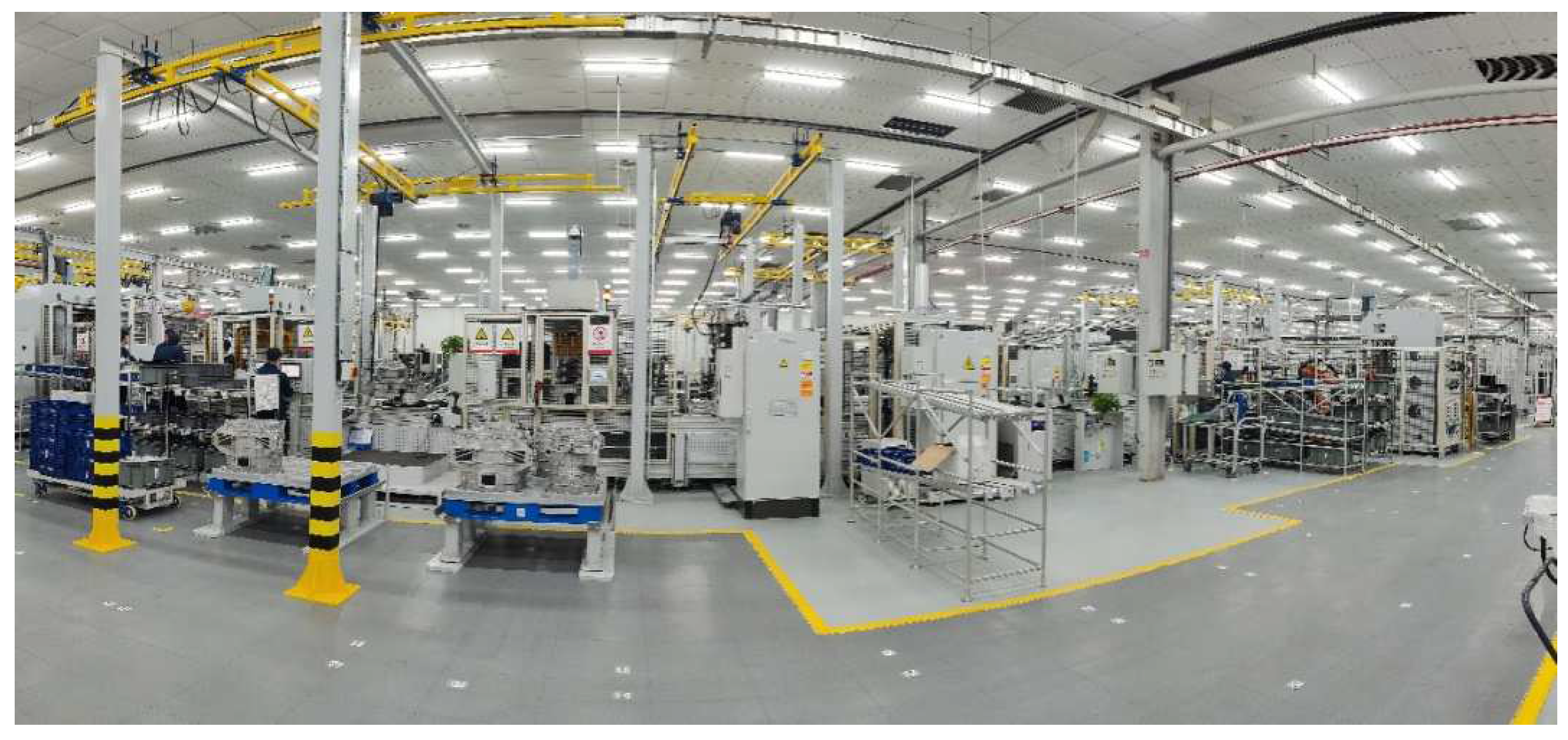
In this paper, a front and middle case assembly in the transmission assembly workshop of an automobile manufacturing enterprise is considered, and the control system is applied on-site. The management and control terminal of this system is developed by Java and installed on the application server in the form of the Windows platform. The executive terminal of this system is developed by Python and Java and installed on the fixed PAD terminal and mobile phones of workers in the form of an application (APP).
Since the transmission is a mass-production product on the assembly line, experiments were performed over a six-month period. Real-time control of the assembly process in the engineering instance was realized through the following operations.
- (1)
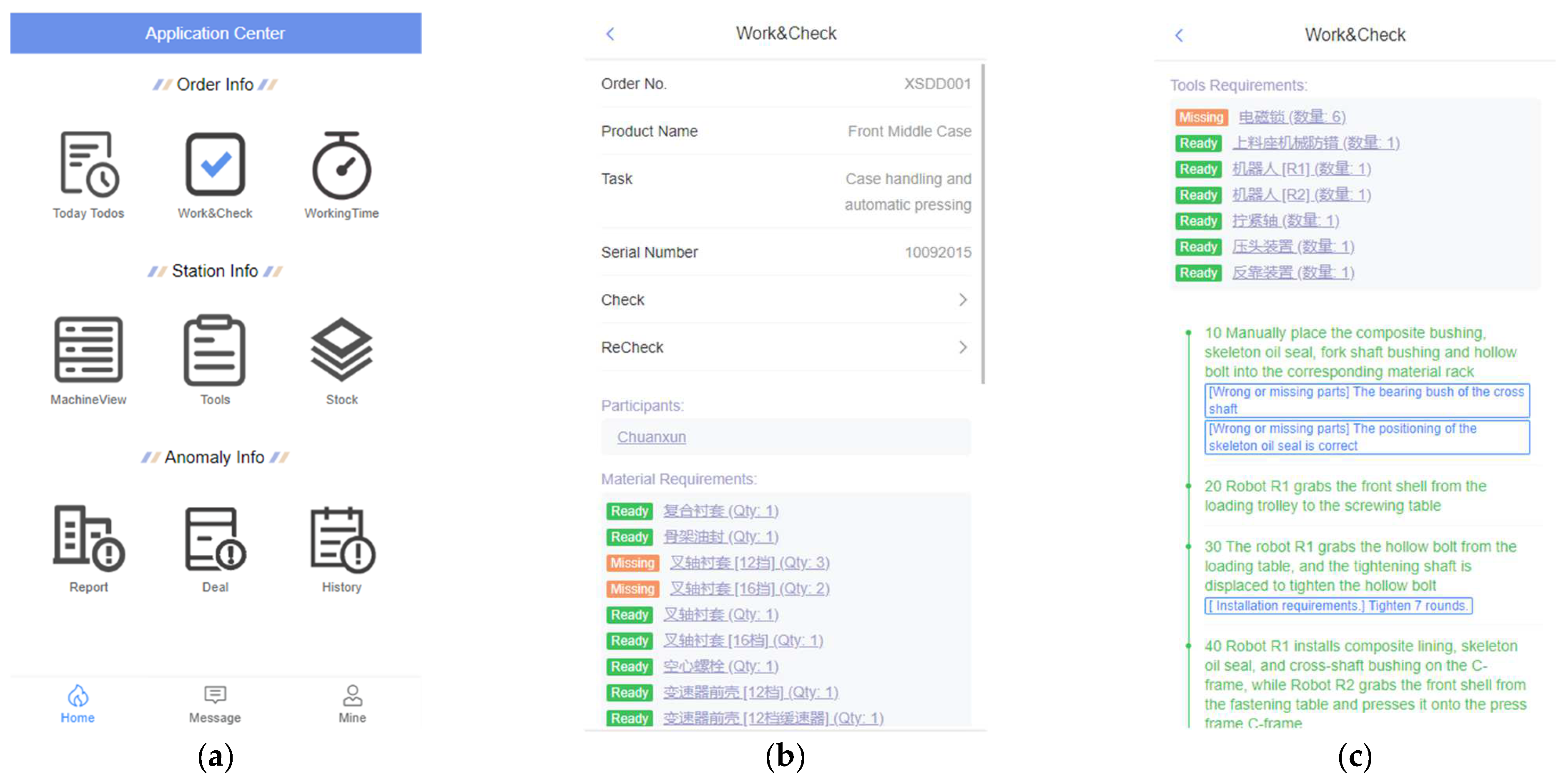
Data integrated management
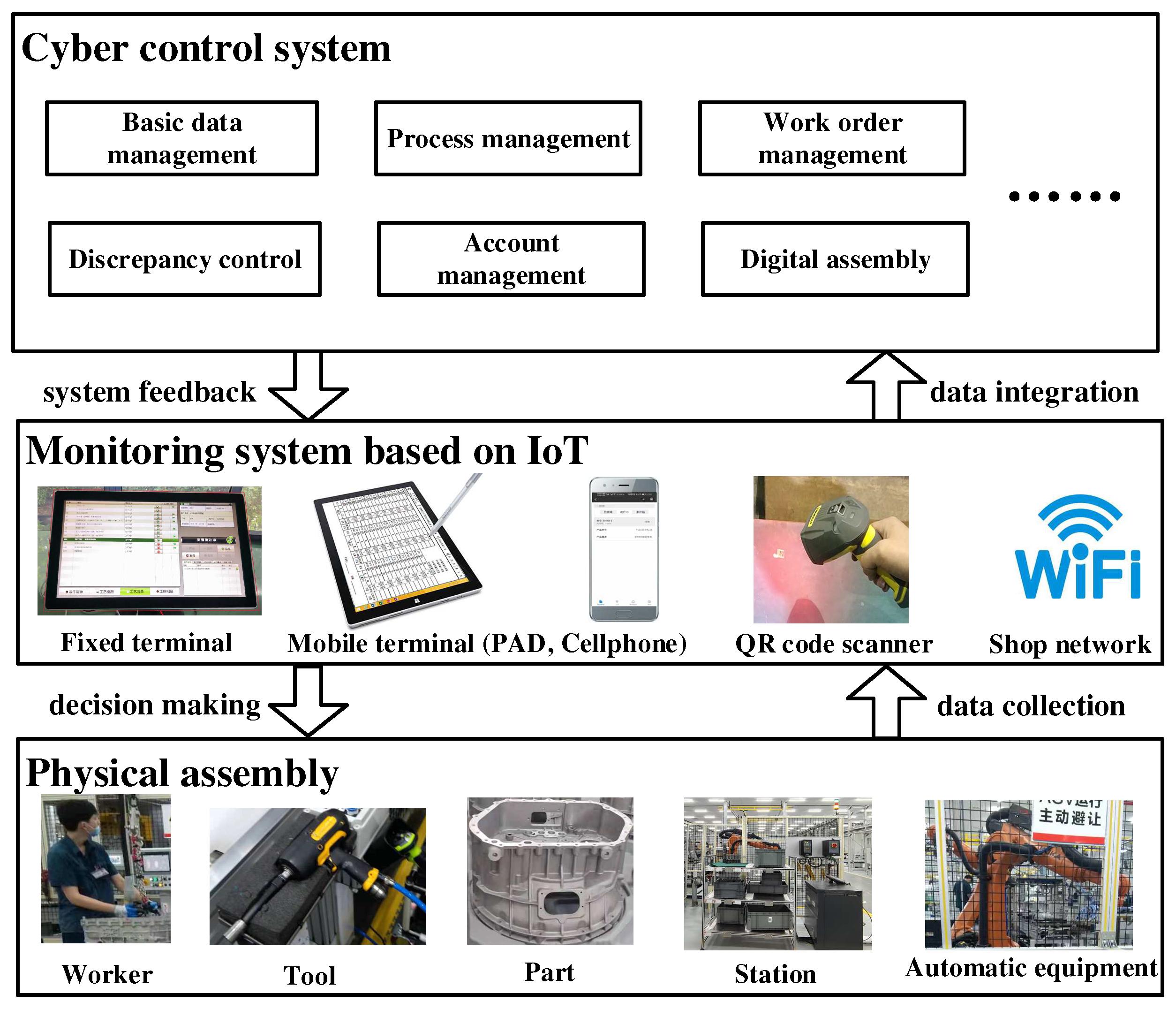
In the engineering instance, work-order information was generated by systems applications and products in data processing (SAP) system and sent to the workshop and the assembly. The corresponding assembly tasks were planned by the workshop group leader and sent to the corresponding workers. Tools, materials, and other resource information were provided by a manufacturing execution system (MES), and information on automation equipment was obtained from the programmable logic controller (PLC). Interfaces between the constructed system in this paper and these systems were developed, and all of the data from these systems were unified, defined, and managed under the support of the data model in the proposed system.
- (2)
Monitor of assembly worker
According to the radio frequency identification (RFID) data acquisition scheme of assembly workers, both the workers involved in the assembly tasks and their working time can be obtained from this system. When the assembly workers are within the RFID sensing range, the corresponding workers’ information can be queried through the RFID signal. If a task is in process, the working time of the participating workers is increased correspondingly. When the assembly task is completed, the total working time of the participating workers can be obtained.
- (3)
Monitor of logistics
Logistics distribution of assembly resources (tools, parts, and materials) is accompanied by the work order. The large assembly resources are placed in trays with RFID tags and distributed by automated guided vehicles (AGVs). Each of them is labeled by a two-dimensional code. The workers receive them through scanning, and the corresponding received information (receiver, receiving time, receiving station, etc.) is recorded in the system. Administrators and workers can access relevant information at any time. The small assembly resources are distributed directly to the line inventory before production.
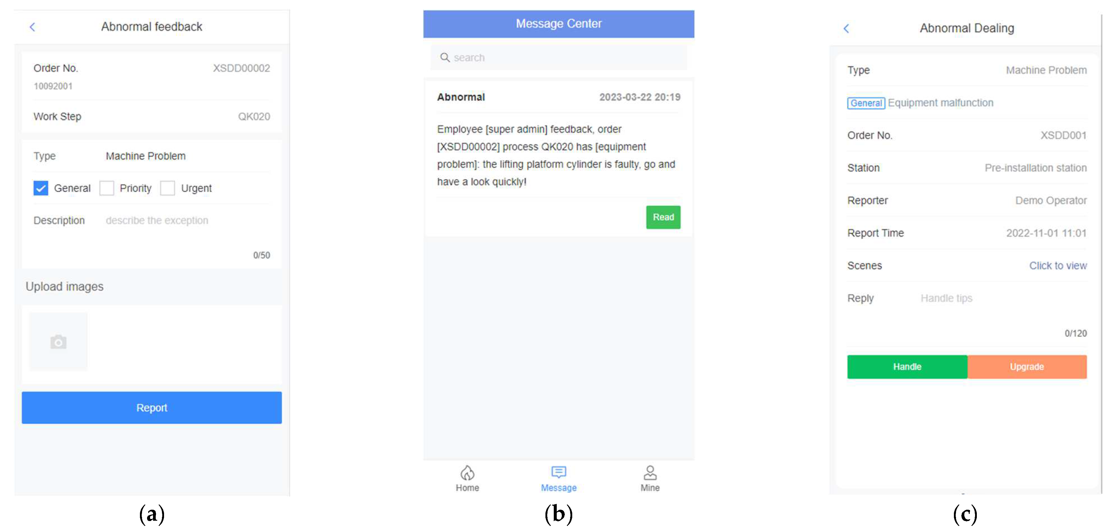
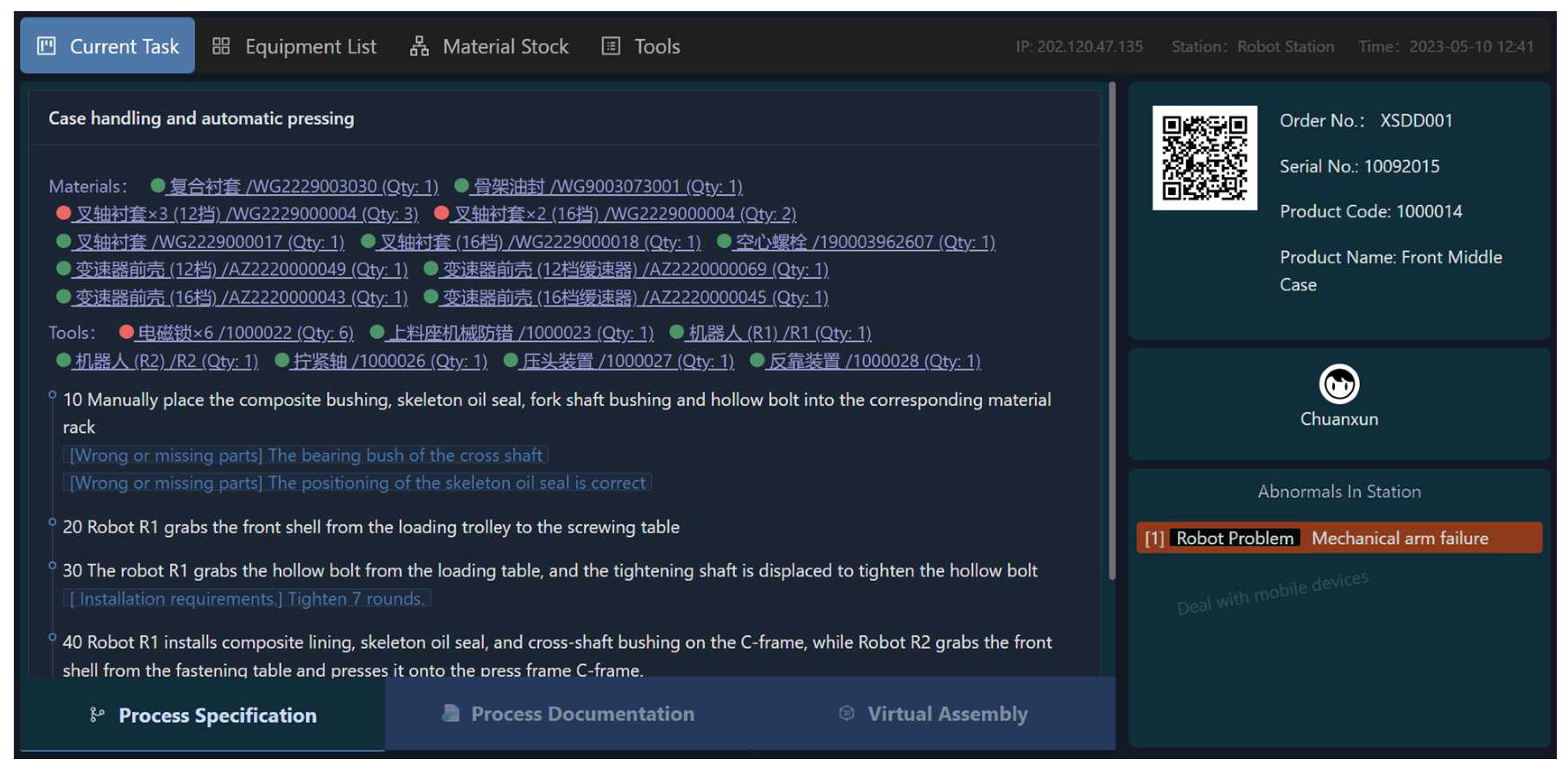
- (4)
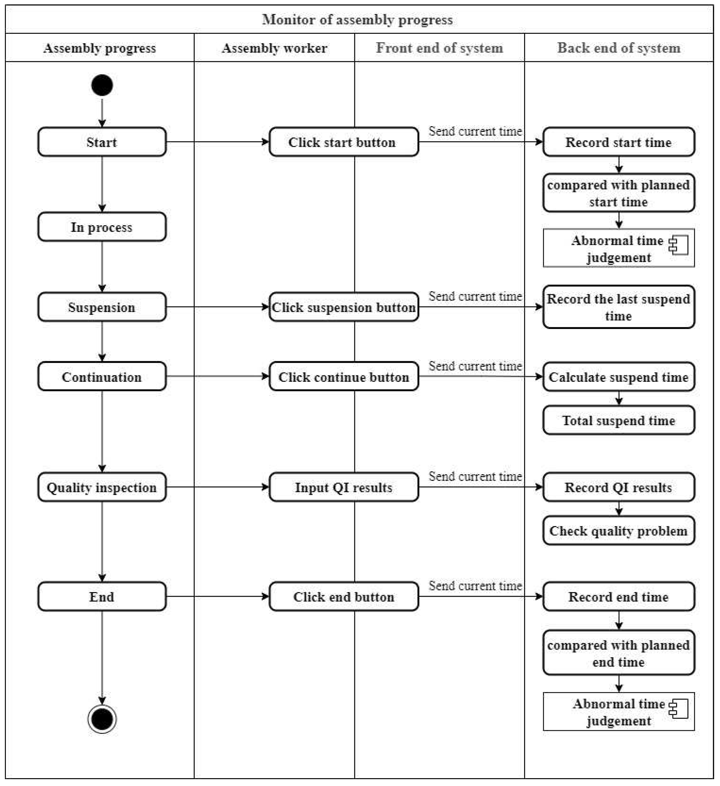
Monitor of assembly progress
The assembly progress, i.e., the execution state of the process, is fed back by workers in the fixed terminal or the mobile terminal. It usually contains five state points: start, suspension, continuation, completion, and end. As shown in
Figure 8, by comparing the recorded start and end times and the initial planned ones, we can determine whether the assembly progress lags behind. And the abnormal assembly quality can also be detected timely according to the quality inspection results before the end of the assembly. The worker should report the abnormality, and the abnormality handle module will be triggered when the assembly schedule lags behind, or the quality is abnormal.
Through the application of the proposed system in a Chinese automobile manufacturing enterprise for a period of time, conclusions can be drawn that all of the above operations are conducive to the timely discovery and handle abnormalities of the worker shortage, untimely resource distribution, and abnormal quality, as well as the adjustment and optimization of assembly schedule in case of progress deviation. The result is the improvement of assembly efficiency and line balance, etc.
5.2. Performance Analysis of the Proposed System
To gain a more comprehensive and digitized analysis of the proposed system, system performance is verified and described from four different aspects of the completion rate of the process data, the production factor coverage rate, the physical control rate, and the line balance rate.
- (1)
Completion rate of process data
As a highly-automated assembly line, the workshop had already collected and mastered some data related to the transmission front and middle case assembly line and its operation. However, due to the existence of manual stations and the inability of the workshop MES system to directly and real-time manage the entire operation process of the assembly line, the current data control of the enterprise was still insufficient.
The completion rate of the process data is a measure of the degree to which the system can master the process data related to assembly-line operation, such as production resources, logistics, and so on. It is the basis of whether the workshop can control the assembly schedule in real time and accurately. As shown in Equation (1).
KPN represents the sum of process elements in a system, while KPNA represents the sum of process elements in an assembly line that needs to be managed systematically.
KPNA is divided according to the principle of “person–machine–material–method–quality inspection“. The specific contents are listed in
Table 1. Then the calculations of KPN and KPNA by Equations (2) and (3).
n is the total number of work steps included in the line, that is, i = {1, 2, 3…n}. J is the total number of processes included in the line, i.e., j = {1, 2, 3,…, J}.
- (2)
Production factor coverage rate
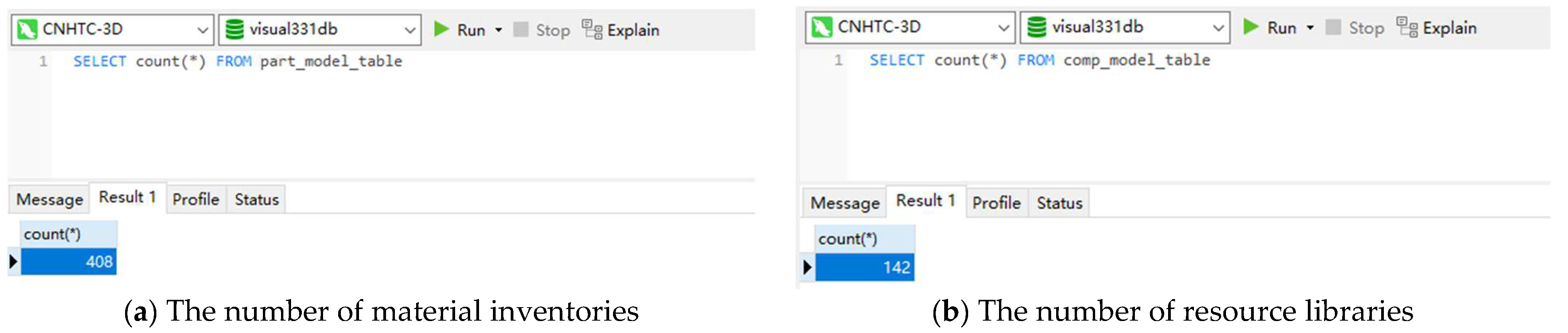
Production factor coverage rate mainly measures the degree to which the system can master a 3D visualization model of the factors of production, i.e., equipment and parts. It is an important index to measure the digitization level of the system and can be calculated by Equation (4).
TNPFs represents the total number of 3D visualization models of equipment and parts contained in the proposed system, and TNPFl represents the total number of equipment and parts contained in the transmission front and middle case assembly line. TNPFs can be counted from the project files of material inventories and resource libraries of the system, as shown in
Figure 9.
- (3)
Physical control ratio
Physical control is basically similar to process but with slight differences. For example, what is described in the process is the configuration of workers, but the actual number of workers in the physical control, as shown in
Table 2. physical control ratio can be calculated by Equation (5).
TNPEs represents the total number of physical entities controlled by the system, and TNPEl represents the total number of physical entities involved in the transmission front and middle case assembly line.
- (4)
Line balance rate
Assembly line balance is to average all the processes of assembly and adjust the working load so that the operation time of each station is as close as possible. Assembly line balance is the key to ensuring the long-term stable operation of the line. Line balance rate is a direct measure index of the level of assembly line balance, as shown in Equation (6).
Although the assembly line has been well planned in the design stage, there will be a large deviation in the actual operation. As shown in
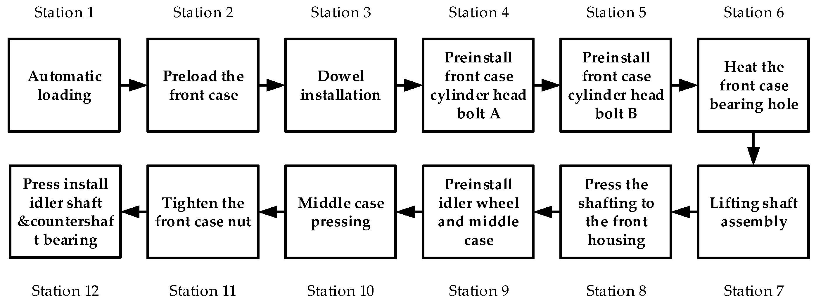
Table 3, the assembly line of the transmission front and middle case contains 12 stations, and the maximum load of all stations is 178 s.
By observing the operation of a period of time, it can be found that the worker allocation, the division of working procedure, and the division of workstations are unreasonable in the current assembly line, as well as the optimized strategies proposed. For example, stations 4, 5, and 11 can be operated by multiple people, and their operation time can be reduced by configuring multiple people to work at the same time. The operation tasks of stations 6, 7, and 8 all belong to the shafting installation, which could be combined into a station, and some of their operations can be combined or performed in parallel. The work tasks of stations 9 and 10 are to complete the middle case on-line, which could be combined into a station, and the operation of pre-installation of the idler component is closely related to the idler assembly in part assembly line; therefore, it can be moved to the part assembly line to ensure it can be pre-installed in advance. The nuts on the side are not easy to operate, and the time fluctuates greatly. Its operation time is effectively reduced by improving the design of the tooling, eventually. In addition, logistics optimization can also be carried out to ensure the timely replenishment of case materials.
After the above optimization, the operation contents of each station and their operation time are optimized, as shown in
Table 4. Then the line balance rate is increased to 89.37%.
- (5)
Downtime ratio
For a highly automated assembly line, the downtime ratio of equipment is one of the indicators that cannot be ignored to restrict the stable operation of the assembly line. Downtime ratio is calculated by Equation (7).
Dn means the number of downtimes, PC represents production capacity, and Dn and PC are both statistics of the line running for a period of time. According to exception statistics, only critical exceptions can cause downtime, as shown in
Table 5.
Eventually, the value of the completion rate of the process data, production factor coverage rate, physical control ratio, and line balance rate before and after CPS (i.e., the use of this system) is shown in
Table 6.
It can be concluded from
Table 6 that the system developed in this paper is successful because most of the key process data, operation data, and physical entities are mastered. This also explains from a scientific point of view why the proposed system can achieve good results on-site; that is, guiding actual production, significant and timely control of the process data and physical entities, as well as extensive coverage of the key factors. Furthermore, it is verified that our system is very valuable in improving the line balance rate and downtime ratio, which are the results of the actual operation of the system on the production site following the actual production line for a period of time. The result shows the effectiveness of the research method in this paper; on one side, the operation process of the assembly line can be further controlled, and the actual production can be guided by the mastery of real-time data and physical entities of the proposed system. On the other side, the actual production process can be optimized effectively through the system’s timely feedback and processing when meeting exceptions. Secondly, it also demonstrates that the cyber–physical fusion technology as a new method to solve the production process’ optimization control under the environment of Industry 4.0 has great advantages and development prospects. In addition, another conclusion can be inferred that the cost optimization will be considerable with the long-term use of this system. Finally, a conclusion can be drawn that it is feasible for manufacturing enterprises to improve manufacturing efficiency through the digital transformation of production lines.


