Article

IQM Mitigation Algorithm with Channel Awareness for Upstream SC-FDMA Systems in the Context of Dual-Hop Broadcasts

1
Smart Systems Engineering Laboratory, College of Engineering, Prince Sultan University, P.O. Box 66833, Riyadh 11586, Saudi Arabia
2
Department of Information Technology, College of Computer and Information Sciences, Princess Nourah bint Abdulrahman University, P.O. Box 84428, Riyadh 11671, Saudi Arabia
*
Authors to whom correspondence should be addressed.
Appl. Sci. 2023, 13(10), 5838; https://doi.org/10.3390/app13105838
Submission received: 11 March 2023 / Revised: 1 May 2023 / Accepted: 6 May 2023 / Published: 9 May 2023

Abstract

:
A challenging issue for single carrier frequency division multiple access (SC-FDMA) transmissions is in-phase and quadrature-phase mismatch (IQM). There has been prior reporting on this issue; however, it has always been in the setting of single-hop broadcasts. This study explored the problem of IQM in multiple users upstream SC-FDMA networks within the framework of amplify-and-forward (AF) dual-hop transmissions. We got closer to realistic scenarios by supposing that each node in the network creates its own IQM. Moreover, we profited from the channel decoders that are included in most wireless standards to provide a valuable aid to the offered estimator. A mathematical analysis revealed that IQM originating from all nodes can be merged into channel coefficients to provide so-called effective channel coefficients. This eliminates the requirement for a chain of algorithms to be employed at each node to estimate and adjust for IQM, as well as the algorithms needed to evaluate channel coefficients between the base station and each node in the network. A theoretical investigation showed that the maximum likelihood (ML) solution to the effective channel coefficients estimation is too complicated to be applied in reality. Alternatively, we employed a simple methodology relying on the space-alternating generalized expectation maximization (SAGE) process to determine the ML predictions of the required parameters. The proposed approach incorporates a feedback loop in which the estimator and the channel decoder exchange information to boost one another’s efficiency. Furthermore, we detail how to execute data detection by making use of the predicted effective channel coefficients. The simulation results verify the effectiveness of the proposed approach and show that it outperforms the current methods.

1. Introduction

The need for high data rate transmissions has contributed to the enormous growth of the wireless communications systems industry over the last several decades and this trend is anticipated to intensify in the next decade [1,2]. The use of multicarrier technology is essential in the development of modern broadband wireless services [3]. The core concept of this technology is to split the data being broadcast into a large number of smaller sub-streams, each of which is then sent over a separate sub-channel. The key benefits of multicarrier transmissions are their resistance to frequency selective fading channels and the simplified signal processing that results from equalizing the signal with only a single tap in the frequency domain [4,5]. Digital video and audio broadcasting, wireless local area networks, and high speed digital subscriber lines are just a few examples of wireless communication systems that have recently adopted this technology as their physical layer of choice [6,7,8,9,10]. Orthogonal frequency division multiple access (OFDMA) and single carrier frequency division multiple access (SC-FDMA) methods are just types of multicarrier transmissions used in the downstream and upstream situations, respectively, of fourth-generation cellular networks [11,12].
While OFDMA shares the available bandwidth among subcarriers, SC-FDMA assigns the available bandwidth to a single subcarrier. When mapping data to the parallel subcarriers in OFDMA, envelope fluctuation happens, which leads to a high peak-to-average-power ratio (PAPR). SC-FDMA has a reduced PAPR in upstream communications, which facilitates the construction of cost effective amplifiers and increases the transmit power efficiency of mobile terminals, hence extending battery life. Such advantages make SC-FDMA more desirable in wireless communications systems. Therefore, it is adopted in the long-term evolution of upstream wireless standards. It is also adopted in new 5G communication networks such as machine-to-machine communications and green communications [13,14].
The dual-hop approach is an additional essential method for improving the performance and reliability of communications systems without the need to deploy numerous antennas, which raise the device’s price, power utilization, and size [15,16,17]. By using neighboring nodes, the broadcast signal can be replicated and sent to the recipient through several, potentially unreliable, fading pathways. Hence, we are able to achieve spatial diversity, which boosts the efficiency of the system. It is also crucial in scenarios when the receiver is beyond the range of the transmitter. With the assistance of dual-hop communications, the range of a signal can be increased without resorting to excessive power. Due of these benefits, dual-hop communications have been adopted for usage in a wide variety of wireless contexts, including but not limited to mobile communications, wireless sensor networks, the internet of things, and microwave and satellite communications [18,19,20]. Amplify-and-forward (AF) and decode-and-forward (DF) are the most prevalent techniques employed by a relay to accomplish dual-hop communications. The complexity of the system is increased by DF since it conducts demodulation and decoding, while the AF method merely amplifies and transmits the signal [21].
Multicarrier and dual-hop communications are susceptible to radio frequency deficiencies such as in-phase (I) and quadrature-phase (Q) mismatch (IQM) [22]. Simply, the IQM is any departure from the condition in which the sine and cosine chains have a 90 phase shift and equal amplitudes. In the analog domain, where low cost manufacturing processes are often used, perfect IQ matching is not feasible. This mismatch is becoming increasingly common as the complementary metal-oxide semiconductor (CMOS) technology becomes more extensively used owing to their lower cost and simplicity of incorporation with digital baseband processing [23,24]. In addition, as carrier frequencies rise, the IQM will become more severe and difficult to eradicate. Mismatches created in the analog domain may be remedied by the development of effective procedures in the digital domain. It is important to keep in mind that these discrepancies are not consistent from chip to chip and are thus impossible to forecast.

1.1. Related Works

Orthogonal frequency division multiplexing (OFDM) systems are very sensitive to the IQM because of the close proximity and spectral overlap of the subcarriers. Due to this reason, subcarrier orthogonality is lost, which in turn produces inter-carrier interference (ICI) and performance deterioration [25]. Consequently, employing advanced equalization methods is necessary to lessen the impact of ICI [26,27]. There is no denying that this dramatically raises the bar for computing complexity. Considering the vast body of literature covering this topic (for examples, see [22,28,29,30] and the citations therein), it is evident that the IQM is a pressing concern. A number of IQM estimate and compensation schemes have been developed, each of which takes into account the IQM at either the recipient or the broadcaster [31,32]. Combined broadcaster and recipient IQM compensating techniques have been developed [33,34]. Integrated structures are presented in [35,36,37] to assess and adjust for channel and IQM at both the broadcaster and the recipient. To evaluate the IQM, dc offset, carrier frequency offset, and channel coefficients simultaneously in frequency selective channels, a maximum likelihood data-aided approach is presented in [38]. The channel assessment is conducted after the computation of IQM as reported in [39]. Recently, the issue of IQM has been debated for multiple input multiple output (MIMO) OFDM systems, see, e.g., [40,41]. A capacity analysis of MIMO OFDM systems with IQM and carrier frequency offset is the focus of [42].
For upstream OFDMA and SC-FDMA systems, the authors of [43] suggest zero forcing and minimal mean square error equalizers, but they assume complete knowledge of the channel impulse response and broadcast IQM. In [43,44], the researchers created a data-aided technique to predict the channel impulse response and broadcast IQM for OFDMA upstream networks using a two-dimensional least square assessment criteria, and they used a zero forcing equalizer to retrieve the information signal. Nevertheless, a practical system model takes into account both the broadcast and receive IQM, which have been ignored in the earlier research [43,44]. The authors of [45] investigated the IQM that occurred at the broadcaster and recipient for bit-interleaved coded modulation transmissions in upstream OFDMA systems.
Symbol error probability over frequency flat channels was calculated analytically in [46,47] by considering AF dual-hop with IQM at the receiving end. The research that examined the effects of IQI in AF two-way [48] provides lower and upper bounds on the average symbol error probability. Mathematical models for the outage probability and ergodic capacity in m-Nakagami fading channels are discussed in the presence IQI at the relay node [49]. Outage performance in the presence of IQM has been studied for a variety of dual-hop OFDM transmissions [50]. Full-duplex OFDM dual-hop systems have inspired research on least-square channel estimators with IQM [51]. It was proposed in [52] that a pilot-based IQM correcting approach would be useful for AF dual-hop OFDM systems. The efficacy of two-way relaying was studied when the IQM is present at the relay terminal [53]. IQM correction and channel assessment methods have been developed for DF two-path consecutive dual-hop OFDM systems [54,55]. The authors of [56] used an expectation maximization technique as a low complexity solution to predict the IQM for AF-OFDM systems with the assistance of a minimal number of pilots.

1.2. Novelty and Contributions

This research set out to develop and evaluate a new prediction and compensation method for IQM in AF dual-hop upstream multiple-user SC-FDMA systems across unreliable frequency-selective wireless channels. The most notable novelties and contributions presented in this article are outlined in the following bulleted list.
  • The previously reported works of estimating and correcting IQM for SC-FDMA systems were accomplished on uncoded single-hop transmissions. This work is the first of its sort that tackles this problem for multiple users upstream SC-FDMA systems over AF dual-hop transmissions.
  • We combined the consequences of IQM that take place at the users, relay, and destination terminals with the channel impulse responses that occur between the nodes to create two unknown elements that are referred to as the equivalent channel impulse response. The proposed approach contradicts the standard, which mandates a variety of techniques for monitoring channel impulse response across nodes and computing the IQM at each terminal.
  • We created a novel approach that uses maximum likelihood principles to evaluate the equivalent channel impulse responses at the destination. We adopted a space-alternating generalized expectation maximization (SAGE) approach for easy implementation of the maximum likelihood algorithm that is being provided.
  • We profited from the channel-decoder’s outputs by computing the a posteriori expectations of the data symbols, which were then employed as training symbols. This was possible due to the widespread usage of error-control codes in a wide range of practical applications.
  • We demonstrated how the decoding procedure was executed using the calculation of the unknown variables.
Table 1 provides a summary of the contributions of previous works and the current study.
The arrangement of the remaining sections of the work is broken down as follows. Section 2 discusses the multiple users upstream SC-FDMA system model with IQM happening at each node in the context of AF dual-hop transmissions. Section 3 describes the offered SAGE computation algorithm. Section 4 introduces crucial considerations for using the provided estimator in practice. Section 5 outlines the process of data detection using the computation of the unidentified parameters. Section 6 provides the simulation results together with a relevant analysis. Section 7 concludes the investigation by summarizing its findings.

2. System Description

As indicated in Figure 1, we investigated a radio upstream multiple users SC-FDMA scheme with K operating users in the context of dual-hop broadcasts. The relay employed an AF routing protocol and operated in a half-duplex mode, which meant that emissions and receptions are separated in time. There were K distinct subsets of the total number of subcarriers N . Each subset contained M = N / K separate subcarriers, each of which was used by one user at a time. Quantitatively, the subset of subcarriers allotted for user k, Q ( k ) , fulfilled k = 0 K 1 Q ( k ) = 0 , 1 , , N 1 and Q ( k ) Q ( k ) = ϕ for k k , with ϕ denoting the empty set.
Figure 2 shows the basic structure of the users’ transmitters, relay, and destination nodes. A channel-control encoder operating at rate r ( k ) appends redundancy bits to a stream of binary data belonging to user k in order to compensate for faults introduced during the broadcast. The encoded bits are interleaved and then transferred to complex-valued information symbols drawn from a specified signal pattern Ω ( k ) of unit energy. Here, the modulator, encoder, and interleaver settings used by each user are completely unrestricted. In order to kick off the estimation procedure, a small number of known symbols are inserted into information symbols. Each of the G ( k ) vectors in the resultant chain contains M symbols. We denote d g ( k ) = d g ( k ) 0 , , d g ( k ) M 1 as the gth vector, with d g ( k ) m being its mth component. Using the M-point fast Fourier-transform (FFT) algorithm, the frequency-domain observations f g ( k ) = f g ( k ) 0 , , f g ( k ) M 1 are described as [57,58]
f g ( k ) m 1 = m 2 = 0 M 1 d g ( k ) m 2 exp j 2 π m 1 m 2 / M ,
where f g ( k ) m 1 is the m 1 th sample of f g ( k ) and j = 1 . The components of f g ( k ) activate M subcarriers using an interleaved mapper, which is described as
x ˜ g ( k ) ( m 1 ) = f g ( k ) ( m 2 ) m 1 = k + m 2 M 0 otherwise ,
and a localized mapper specified as
x ˜ g ( k ) ( m 1 ) = f g ( k ) ( m 2 ) m 1 = m 2 + k M 0 otherwise ,
where 0 k K 1 . Using an N-point inverse FFT (IFFT) with incorporating a cyclic prefix of length ν , we transform f g ( k ) into an SC-FDMA symbol, s g ( k ) = s g ( k ) ν , , s g ( k ) N 1 , as
s g ( k ) n 1 = n 2 = ν N 1 x ˜ g ( k ) n 2 exp j 2 π n 1 n 2 / N ,
where s g ( k ) n 1 is the n 1 th sample of the gth SC-FDMA symbol, s g ( k ) , of user k. Therefore, the entire sequence sent by user k is expressed as s ¯ ( k ) = s 0 ( k ) , , s G 1 ( k ) , where † is the complex-conjugate action. We represent θ ( k ) and ρ ( k ) as the phase and amplitude mismatches between I and Q routes at the transmitter of user k . The signal damaged by the IQM at user k is described as [59]
s ( k ) = η ( k ) s ¯ ( k ) + μ ( k ) s ¯ ( k ) ,
where η ( k ) and μ ( k ) are defined as
η ( k ) = cos θ ( k ) + j ρ ( k ) sin θ ( k ) ,
μ ( k ) = ρ ( k ) cos θ ( k ) + j sin θ ( k ) .
The following is a breakdown of the broadcast schedule.
User k sends the vector s ( k ) via two radio connections to concurrently reach the relay and the destination terminals during the first time period. We denote h R ( k ) = h R ( k ) 0 , , h R ( k ) L 1 and h D ( k ) = h D ( k ) 0 , , h D ( k ) L 1 as the radio links that exist between user k and relay, and user k and destination, respectively, with L being the number of link taps. The collected signals at the relay and destination are described as
y R = k = 0 K 1 s ( k ) h R ( k ) + n R ,
y D ( 1 ) = k = 0 K 1 s ( k ) h D ( k ) + n D ( 1 ) ,
where ⊗ is the convolution action, and n R and n D ( 1 ) are the noise vector at the relay and destination nodes, respectively. Considering the impact of of IQM on y R and y D ( 1 ) , we obtain
y ¯ R = η R y R + μ R y R ,
y ¯ D ( 1 ) = η D y D ( 1 ) + μ D y D ( 1 ) ,
where η R , μ R , η D , and μ D have the same format as those in (6) and (7). In the second time period, the relay then rebroadcasts the adjusted signal to its original destination. The gathered vector at the destination is given as
y D ( 2 ) = Δ y ¯ R h R D + n D ( 2 ) ,
where h R D = h R D 0 , , h R D L 1 is the radio link between relay and destination terminals, n D ( 2 ) is the noise samples, and Δ is the scaled factor. The IQM effect on y D ( 2 ) yields
y ¯ D ( 2 ) = η D y D ( 2 ) + μ D y D ( 2 ) .
The goal of this study was to create a data detection technique while making simultaneous forecasts for all unidentified parameters of h R ( k ) , h D ( k ) , h R D , η ( k ) , μ ( k ) , η R , μ R , η D , and μ D for k = 0 , 1 , , K 1 .

3. Proposed SAGE Estimation Algorithm

The primary duty of the destination is to make use of the y ¯ D ( 1 ) and y ¯ D ( 2 ) observations in order to recover the data that were sent by different users. Hence, it is required to determine the IQM parameters of each user, relay, and destination, as well as the radio links connecting the different nodes. Using (5), (9), into (11), we express y ¯ D ( 1 ) and y ¯ D ( 2 ) as
y ¯ D ( 1 ) = k = 0 K 1 s ¯ ( k ) H D , 1 ( k ) + s ¯ ( k ) H D , 2 ( k ) + n ¯ D ( 1 ) ,
y ¯ D ( 2 ) = k = 0 K 1 s ¯ ( k ) H D , 3 ( k ) + s ¯ ( k ) H D , 4 ( k ) + n ¯ D ( 2 ) ,
where
H D , 1 ( k ) = η D η ( k ) h D ( k ) + μ D μ ( k ) h D ( k ) ,
H D , 2 ( k ) = η D μ ( k ) h D ( k ) + μ D η ( k ) h D ( k ) ,
H D , 3 ( k ) = Δ η D η R η ( k ) h D ( k ) h R D + μ ( k ) h D ( k ) h R D + Δ μ D μ R μ ( k ) h D ( k ) h R D + η ( k ) h D ( k ) h R D ,
H D , 4 ( k ) = Δ η D η R μ ( k ) h D ( k ) h R D + η ( k ) h D ( k ) h R D + Δ μ D μ R η ( k ) h D ( k ) h R D + μ ( k ) h D ( k ) h R D .
Since we recall that a convolution process can be performed via matrix multiplication, we can reformat (14) and (15) as [60]
y ¯ D ( 1 ) = k = 0 K 1 S ( k ) H 1 ( k ) + n ¯ D ( 1 ) ,
y ¯ D ( 2 ) = k = 0 K 1 S ( k ) H 2 ( k ) + n ¯ D ( 2 ) ,
where H 1 ( k ) = H D , 1 ( k ) H D , 2 ( k ) , H 2 ( k ) = H D , 3 ( k ) H D , 4 ( k ) , S ( k ) = S ( k ) S ( k ) , and S ( k ) is the broadcast matrix constructed as
S ( k ) = s 0 ( k ) 0 0 0 0 s 1 ( k ) s 0 ( k ) 0 0 0 s 2 ( k ) s 1 ( k ) s 0 ( k ) 0 0 s e 1 ( k ) s e 2 ( k ) s e 3 ( k ) s e L 2 ( k ) 0 s e 1 ( k ) s e 2 ( k ) s e L 3 ( k ) 0 0 0 0 s e 1 ( k ) .
Here s i ( k ) is the ith element of the vector s ¯ ( k ) , i = 0 , 1 , , e 1 , where e is the vector length. The mth raw of S ( k ) is provided by time reversing the mth element until the ( m + L 1 ) element of vector s ¯ ( k ) . For example, the first raw is constructed as s 0 ( k ) , 0 1 × ( L 1 ) , the second raw is created as s 1 ( k ) , s 0 ( k ) , 0 1 × ( L 2 ) , and so forth. Because of these architectures, we can predict just two variables, H 1 ( k ) and H 2 ( k ) , as opposed to 2 K + 4 values of η D , μ D , η R , μ R , η ( k ) , and μ ( k ) for k = 0 , , K 1 . The ML evaluations of H 1 ( 0 ) , H 2 ( 0 ) , , H 1 ( K 1 ) , H 2 ( K 1 ) are obtained by maximizing the log-likelihood function as
H ^ 1 ( 0 ) , H ^ 2 ( 0 ) , , H ^ 1 ( K 1 ) , H ^ 2 ( K 1 ) = arg max H 1 ( 0 ) , H 2 ( 0 ) , , H 1 ( K 1 ) , H 2 ( K 1 ) log Pr y ¯ D ( 1 ) , y ¯ D ( 2 ) S ( 0 ) , , S ( K 1 ) , H 1 ( 0 ) , H 2 ( 0 ) , , H 1 ( K 1 ) , H 2 ( K 1 ) ,
where Pr | describes the probability density function of ⋄ given ◃, and ^ corresponds to the predicted value of ⋄. Given that y ¯ D ( 1 ) and y ¯ D ( 2 ) are independent sequences, we express
Pr y ¯ D ( 1 ) , y ¯ D ( 2 ) S ( 0 ) , , S ( K 1 ) , H 1 ( 0 ) , H 2 ( 0 ) , , H 1 ( K 1 ) , H 2 ( K 1 ) = Pr y ¯ D ( 1 ) S ( 0 ) , , S ( K 1 ) , H 1 ( 0 ) , , H 1 ( K 1 ) × Pr y ¯ D ( 2 ) S ( 0 ) , , S ( K 1 ) , H 2 ( 0 ) , , H 2 ( K 1 ) ,
where
Pr y ¯ D ( 1 ) S ( 0 ) , , S ( K 1 ) , H 1 ( 0 ) , , H 1 ( K 1 ) exp 1 σ n 2 y ¯ D ( 1 ) k = 0 K 1 S ( k ) H 1 ( k ) 2 ,
and
Pr y ¯ D ( 2 ) S ( 0 ) , , S ( K 1 ) , H 2 ( 0 ) , , H 2 ( K 1 ) exp 1 σ n 2 y ¯ D ( 2 ) k = 0 K 1 S ( k ) H 2 ( k ) 2 .
Here, σ n 2 describes the variance of the additive white Gaussian noise. Equations (20)–(23) reveal that knowing the broadcast matrices S ( 0 ) , , S ( K 1 ) in advance is required for the precise ML solution, although this information is typically unattainable at the destination.
Direct computations of maximum likelihood value predictions are problematic in a number of signal processing scenarios owing to the complexity of the likelihood functions or the coupling created by the smoothness penalties or priors. In such situations, the expectation maximization process is often used to provide parameter estimates with the greatest likelihood in an iterative manner [61,62,63]. The basic idea is to rotate between executing an expectation (E) step, which constructs a function for the expected log-likelihood assessed using the latest assessment for the variables, and a maximization (M) step, which evaluates variables optimizing the expected log-likelihood determined on the E step. During the following E step, these variable-predictions are utilized to calculate the distribution of the observed variables. This solution is particularly beneficial when the M-step is simpler than optimizing the initial likelihood. A conventional expectation maximization algorithm’s concurrent updating needs too-informative complete-data spaces, which leads to sluggish convergence [64]. In general, an expectation maximization process’s convergence speed decreases as its full-data space’s Fisher information increases [65]. Hence, a significant number of iterations is necessary to achieve a satisfactory performance level. Fessler developed the SAGE approach in 1994 to speed up the convergence time of the expectation maximization process for multidimensional parameter estimation. As compared to the standard expectation maximization process, the SAGE algorithm differs in that it successively updates groups of parameters rather than all of them at once. It was shown in [66] that the SAGE process converges more quickly than the expectation maximization procedure while preserving the benefits of computational simplicity and stability. In recent years, SAGE has been used in a great number of studies including the estimate of the direction-of-arrival, and channel estimation and synchronization for upstream scenarios [67,68].
Theoretical details of the SAGE procedure devised for calculating the parameters under consideration are described as follows. We generate K separate subgroups, none of which are identical to one another; H 1 ( 0 ) , H 2 ( 0 ) , ⋯, H 1 ( K 1 ) , H 2 ( K 1 ) . Alterations to the parameters are made on a one-by-one basis across all of the users. Each round is made up of K cycles in which a user’s subgroup is modified. Given the early guesses, H ^ 1 ( 0 ) ( 0 ) , H ^ 2 ( 0 ) ( 0 ) , ⋯, H ^ 1 ( K 1 ) ( 0 ) , H ^ 2 ( K 1 ) ( 0 ) , the following steps compose the ζ + 1 round.
  • During the kth loop, the user k subgroup H 1 ( k ) , H 2 ( k ) is updated, while the subsets of all other users remain unchanged.
  • By conducting time domain multiple access interference cancellation, we are able to retrieve the received signal for user k, denoted by z ( k ) , by eliminating the contributions from all users except user k. We can formally express
    z 1 ( k ) = y ¯ D ( 1 ) k = 0 , k k K 1 A ( k ) H ^ 1 ( k ) ζ ,
    z 2 ( k ) = y ¯ D ( 2 ) k = 0 , k k K 1 A ( k ) H ^ 2 ( k ) ζ ,
    where
    A ( k ) = S ( k ) S ( k ) Pr S ( k ) y ¯ D ( 1 ) , y ¯ D ( 2 ) , H ^ 1 ( k ) ζ , H ^ 2 ( k ) ζ d S ( k ) .
  • The E-step measures the expected logarithmic likelihood of the observed signal given the conditional distribution of the unobserved data, based on what we know about the unknown parameters so far. This is typically expressed as
    U H 1 ( k ) , H 2 ( k ) H ^ 1 ( k ) ζ , H ^ 2 ( k ) ζ = E log Pr z 1 ( k ) , z 2 ( k ) S ( k ) , H 1 ( k ) , H 2 ( k ) z 1 ( k ) , z 2 ( k ) , H ^ 1 ( k ) ζ , H ^ 2 ( k ) ζ = S ( k ) log Pr z 1 ( k ) , z 2 ( k ) S ( k ) , H 1 ( k ) , H 2 ( k ) × Pr S ( k ) z 1 ( k ) , z 2 ( k ) , H ^ 1 ( k ) ζ , H ^ 2 ( k ) ζ d S ( k ) ,
    where the expectation is executed on the broadcast matrix S ( k ) .
  • By substituting (21), (22), and (23) into (27) and eliminating the unnecessary elements, we obtain
U H 1 ( k ) , H 2 ( k ) H ^ 1 ( k ) ζ , H ^ 2 ( k ) ζ 2 z 1 ( k ) B 1 H 1 ( k ) H 1 ( k ) B 2 H 1 ( k ) + 2 z 2 ( k ) B 3 H 2 ( k ) H 2 ( k ) B 4 H 2 ( k ) ,
where the superscript ‡ is the vector-transpose conjugate, and
B 1 = S ( k ) Pr S ( k ) z 1 ( k ) , H ^ 1 ( k ) ζ d S ( k ) ,
B 2 = S ( k ) S ( k ) Pr S ( k ) z 1 ( k ) , H ^ 1 ( k ) ζ d S ( k ) ,
B 3 = S ( k ) Pr S ( k ) z 2 ( k ) , H ^ 2 ( k ) ζ d S ( k ) ,
B 4 = S ( k ) S ( k ) Pr S ( k ) z 2 ( k ) , H ^ 2 ( k ) ζ d S ( k ) ,
  • Hence, the M-step is derived as
    H ^ 1 ( k ) ζ + 1 , H ^ 2 ( k ) ζ + 1 = arg max H 1 ( k ) , H 2 ( k ) U H 1 ( k ) , H 2 ( k ) H ^ 1 ( k ) ζ , H ^ 2 ( k ) ζ .
    When we zero out the derivative of (28) with regard to H 1 ( k ) and H 2 ( k ) , respectively, we are able to refine the previous estimates of H 1 ( k ) and H 2 ( k ) as
    H ^ 1 ( k ) ζ + 1 = B 2 1 B 1 z 1 ( k ) ,
    H ^ 2 ( k ) ζ + 1 = B 4 1 B 3 z 2 ( k ) .

4. Practical Considerations

The following are a number of realistic remarks that need to be taken into account.
  • The concern that arises is how one would proceed with actually determining the matrices of B 1 , B 2 , B 3 , and B 4 in the real world. Implications from (4) are that
    s g ( k ) n 1 = n 2 = ν N 1 E x ˜ g ( k ) n 2 exp j 2 π n 1 n 2 / N .
    Using (1), (2), and (3), E x ˜ g ( k ) n 2 is expressed as
    E x ˜ g ( k ) n 2 = m 2 = 0 M 1 ϖ Ω ϖ Pr d g ( k ) m 2 = ϖ z 1 ( k ) , z 2 ( k ) , H ^ 1 ( k ) ζ , H ^ 2 ( k ) ζ × exp j 2 π n 2 φ m 2 / M ,
    where φ m 2 is the subcarrier that modulates the m 2 th data symbol of the gth block. As a result, the a posteriori expectation of the matrix S ( k ) = S ( k ) S ( k ) , with S ( k ) being represented in (19), is determined by substituting each element in the matrix with the associated a posteriori expectation computed in (33).
  • Presuming that the information symbols are statistically independent, we can show that B 2 and B 4 are effectively described by B 1 B 1 and B 3 B 3 .
  • Each time we update H ^ 1 ( k ) ζ and H ^ 2 ( k ) ζ , we need to reevaluate the a posteriori probability Pr d g ( k ) m 2 = ϖ z 1 ( k ) , z 2 ( k ) , H ^ 1 ( k ) ζ , H ^ 2 ( k ) ζ . This requires a channel decoder reboot, which substantially increases the sophistication of the data processing. For this reason, we used the embedded estimating strategy [58,69] to eliminate this complication cost. When H ^ 1 ( k ) ζ and H ^ 2 ( k ) ζ are updated, the channel decoder does not start again, but instead recalls the extrinsic and a priori probabilities from the last time it was run. The presented SAGE estimation method has lower costs in this context.
  • The preliminary measurements for H 1 ( k ) and H 2 ( k ) are deduced, employing (31a) and (31b), by assigning the matrices of the B 1 and B 3 to the contribution of the training symbols alone.
  • We provided an estimate of the computational load of the provided estimator in terms of the total number of floating-point operations (flps). Using the same methodology as that described in [21,70,71], we assumed that: the addition and multiplication of two complex numbers needs two and six flops, respectively; the multiplication of two complex matrices whose dimensions are α 1 × α 2 and α 2 × α 3 needs 8 α 1 α 2 α 3 flps; the addition/subtraction of two complex matrices, each with dimension α 1 × α 2 requires 2 α 1 α 2 flps; and the inverse of a complex matrix with dimension α 1 × α 1 needs α 1 3 flops. Using the preceding presumptions in (31b), the number of flps, Λ , per iteration per user of the proposed approach is written as
    Λ = 2 α 1 + 8 α 1 α 2 + 5 Ω α 1 α 2 + α 2 3 + 8 α 2 2 + 16 α 1 α 2 .
    Here, α 1 = G ( N + ν ) + L + 2 G N and α 2 = 3 L 1 3 L . Bearing in mind that α 1 α 2 , the approximated value Λ is
    Λ α 1 α 2 1 + 5 Ω .
    We examined a quantitative case with G = 10 , N = 128 , Ω = 4 , and L = 6 , with an FPGA capable of ten Teraflops of computing power. This produces a run-time of 0.22 usec, which is rapid enough for the majority of applications.

5. Offered Detector

The base station segments the received signals into chunks of N + v samples for processing. The base station suppresses the multiple access interference caused by the transmissions of other users in order to detect the data of user k. Next, we get rid of the v samples that matched the cyclic prefix, keeping N samples for subsequent inspection. After performing N-point FFT, frequency demapping, and M-point IFFT, the mth outputs of the IFFT unit of the gth vector for the first and second-time slots are, respectively, expressed as
R g , 1 ( k ) ( m ) = h 1 ( k ) ( m ) d g ( k ) ( m ) + h 2 ( k ) ( m ) d g ( k ) ( m ) + W g , 1 ( k ) ( m ) ,
R g , 2 ( k ) ( m ) = h 3 ( k ) ( m ) d g ( k ) ( m ) + h 4 ( k ) ( m ) d g ( k ) ( m ) + W g , 2 ( k ) ( m ) ,
where W g , 1 ( k ) ( m ) and W g , 2 ( k ) ( m ) are the noise elements and h x ( k ) ( m ) is the frequency domain channel coefficient that includes the channel response along with the IQM parameters found at user k , relay, and base station, x = 1 , , 4 . We rewrite (36a) and (36b) in a compact vector format as
R g ( k ) ( m ) = h ¯ ( k ) ( m ) d g ( k ) ( m ) + W g ( k ) ( m ) ,
where R g ( k ) ( m ) = R g , 1 ( k ) ( m ) , R g , 2 ( k ) ( m ) , d g ( k ) ( m ) = d g ( k ) ( m ) , d g ( k ) ( m ) , and
h ¯ ( k ) ( m ) = h 1 ( k ) ( m ) h 2 ( k ) ( m ) h 3 ( k ) ( m ) h 4 ( k ) ( m ) .
We write the a posteriori probability of d g ( k ) ( m ) as
Pr d g ( k ) ( m ) R g ( k ) ( m ) , h ¯ ( k ) ( m ) exp 1 σ n 2 R g ( k ) ( m ) h ¯ ( k ) ( m ) d g ( k ) ( m ) 2 Pr d g ( k ) ( m ) .
We presumed that Z ( k ) = log 2 Ω ( k ) bits identify each information symbol, d g ( k ) ( m ) = L b g ( k ) ( m , 0 ) , , b g ( k ) ( m , Z 1 ) , where L · is the label function and b g ( k ) ( k , z ) is the zth bit of the information symbol d g ( k ) ( m ) . Therefore, the bit metric λ b g ( k ) ( m , z ) = o , for o = 0 , 1 , is computed as
λ b g ( k ) ( m , z ) = o = ϑ = F o , z d g ( k ) ( m ) Ω ( k ) Pr d g ( k ) ( m ) R g ( k ) ( m ) , h ¯ ( k ) , d g ( k ) ( m ) = ϑ ,
where
F b , z = L { b g ( k ) ( m , 0 ) , , b g ( k ) ( m , Z 1 ) b g ( k ) ( m , z ) = o .
After de-interleaving, the bit metrics are sent to the channel error-control decoder to derive the a posteriori probability of coded bits. Next, the probabilities are interleaved and transferred to the a posteriori computation unit. The offered estimator and detector algorithms use these probabilities as a priori input, as stated in (31a), (31b), and (39), respectively. The decoder makes hard choices based on the a posteriori probability of the transmitted bits in the last iteration. The conceptual block diagram of the recommended detection and estimation technique is shown in Figure 3. The proposed approach is summarized in Algorithm 1.
Algorithm 1: Summary of the proposed approach.
  • Use a few training symbols to create the matrix S ( k ) , for k = 0 , 1 , , K 1 , with setting unknown data symbols to zeros. Then, employ (31a) and (31b) to obtain preliminary assessments of the unknown parameters H ^ 1 ( k ) 0 and H ^ 2 ( k ) 0 .
  • For ζ = 0 : ρ 1 , where ρ is the total number of iterations
    for each user k , where k = 0 , , K 1 .
    Employ (24) and (25) to remove time-domain multiple access interference.
    If ζ = ρ 1 ,
    use (37)–(41) to decode the sent information symbols of user k,
    else
    employ (32) and (33) to obtain the soft information of the sent information
    symbols of user k. Then, employ (31a) and (31b) to have the updated values of
    H ^ 1 ( k ) ζ and H ^ 2 ( k ) ζ .
    End
    End

6. Simulation Results

The developed estimation and detection methods were evaluated using Monte Carlo simulations to confirm their reliability. We explored a multi-user upstream SC-FDMA system that used a coded AF dual-hop transmission. Unless otherwise indicated explicitly in the article, the following transmission parameters were employed for simulations.
  • There were K = 8 operating users.
  • There were N = 1024 subcarriers in all.
  • The number of allotted subcarriers per user was M = 1024 / 8 = 128 .
  • The cyclic prefix length was ν = 10 .
  • The localized mapper subcarriers distribution was employed.
  • Each user was appointed one of four possible signal architectures, Ω ( k ) , (16-QAM, 64-QAM, 128-QAM, 512-QAM).
  • Each user adopted a convolutional code with a rate of 0.5, a constraint size of 7, and generating polynomials of 25 and 37.
  • Training symbols of length 60 were supplied to kick-start the suggested estimate procedure.
  • Wireless links between user k and the relay node, h R ( k ) , and user k and the destination, h D ( k ) , were created using nine taps where each one was modelled as a complex random variable with a profile being [72]
    σ B k 2 l = Γ B k exp l / 10 , l = 0 , , 9 ,
    where B R , D and Γ B k were chosen in such a manner that the mean energy per subcarrier was set to a certain value chosen at random from an interval of 1 , 2 .
  • IQM parameters of the users, relay, and destination nodes were selected at random as follows: ρ ( k ) , ρ ( R ) , ρ ( D ) 0.91 , 1.6 and θ ( k ) , θ ( R ) , θ ( D ) 0 , 25 o . Here, ρ ( k ) , ρ ( R ) and ρ ( D ) are the IQM gains while θ ( k ) , θ ( R ) and θ ( D ) are the IQM phases at the relay, destination, and user k terminals, respectively.
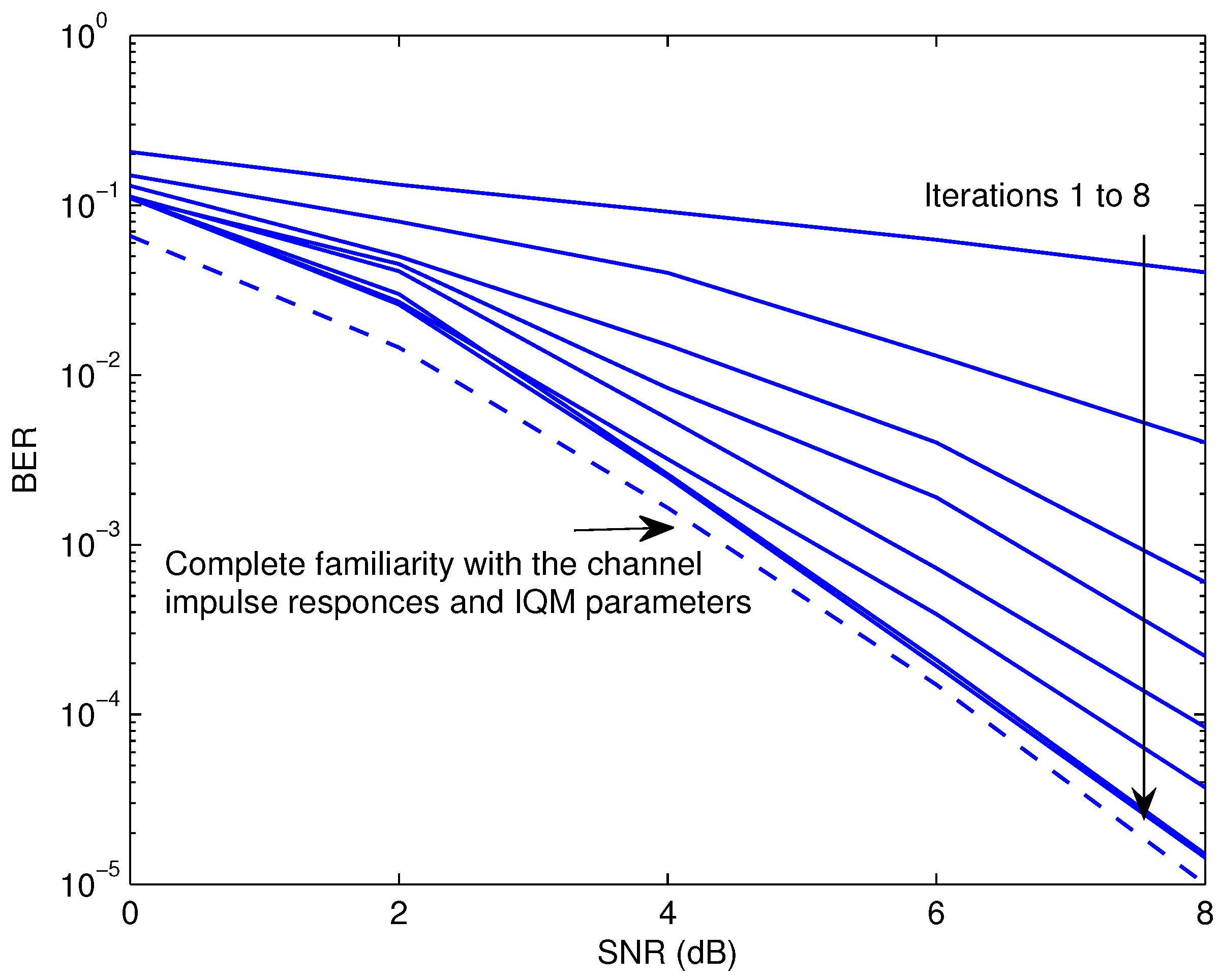
  • For the presented data detector, the bit-error-rate (BER) was employed as a measure of performance, whereas for the IQM and channel assessment, the mean-square-estimation error (MSE) was adopted.
The BER of the provided detector is shown in Figure 4 as a function of the signal-to-noise ratio (SNR), and the MSE of the described estimator is demonstrated in Figure 5. The MSE of a predictor that is fully aware of all information symbols is also illustrated as a reference in Figure 5. This produces a performance limit on MSE. In addition, Figure 4 displays the BER efficacy when all channel impulse responses between terminals and IQM parameters are considered to be perfectly estimated. As can be seen, both the MSE and BER efficiency keep getting better as the repetition approach continues. After eight rounds, the effectiveness of the indicated detector and estimator is remarkably near to that acquired under ideal circumstances of complete channel state information and IQM parameters awareness. The reason for this behavior is elaborated as follows. As the prediction technique is founded on a limited number of pilots, the soft information provided by the supplied detector is untrustworthy in the first iteration. In contrast to the data-assisted scenario, a higher number of iterations leads to the use of more trustworthy information, which improves the accuracy of both the estimation and detection processes.
Figure 6 compares the BER efficiency for the proposed design to that of several other systems. There is a situation with ideal forecasting and compensation for IQM at all nodes of the considered system, as well as the case with no IQM correction. It is clear that IQM, if unadjusted for, would lead to subpar BER efficiency. By all appearances, the presented scheme not only achieves a BER quality that is much better than that reported in [50,51], but it also produces an efficiency that is within 1 dB of the optimum.
The proposed process may also be useful for classic single-hop SC-FDMA operations. It is sufficient to eliminate the channel impulse response between the relay and the base station. This recommended detector, however, functions exactly akin to the ordinary one in this case. Figure 7 compares the BER quality of the planned AF SC-FDMA scheme with the single-hop transmission coupled to the proposed estimator at round 8. The results demonstrate that the dual-hop system is far better than the single-hop one. This is because the dual-hop system maximizes diversity benefits by transmitting waveforms across both main and relayed channels.
It is well-known that SAGE-based strategies depend critically on having an efficient starting point. Figure 8 illustrates the BER effectiveness of the mentioned detector and estimator as a function of the training symbols length, T , at SNR = 4 and 8 dB. The proposed estimator clearly has a convergence level of more than 60 known symbols. It is worth noting that, depending on the transmission parameters and the linkages, the basic requirement of pilots needed to provide accurate initial estimations may change. The designer can put the offered estimation method to work across a broad variety of network and link parameters to find out how few pilots are required to meet all the requirements. The findings are recorded in look-up tables for later use in the actual hardware. Additionally, the designer can pick a sufficiently large random sample of pilots to account for many different configurations of the network and its links.
Figure 9 presents the BER performance of the proposed approach as a function of the number of operating users at SNR = 8 dB. The findings show that, when the number of users increases, the suggested method’s BER performance degrades marginally. This is due to the fact that increasing the number of active users increases the residual multiple access interference, which reduces BER performance. Furthermore, we observed a substantial performance boost compared to the algorithms described in [50,51]. This is because the aforementioned algorithms do not profit from the features inherent in channel coding transmissions.
In prior discussions, it was presumed that the wireless channels remained constant during the observation period, i.e., their coherence times approached infinity. Figure 10 illustrates the impact of the maximum Doppler shift, d s , on the BER performance of the proposed approach at SNR = 8 dB. Here, d s was normalized to the sampling frequency. An improved version of the Jakes model [69] was used to represent the time-selective nature of the wireless links. We also display the results of the methods described in [50,51] for the purpose of comparison. The results indicate that the proposed approach achieves adequate BER performance when d s 10 4 . This demonstrates that the suggested technique works well in quasi-stationary settings. However, the algorithms reported in [50,51] are unable to provide acceptable outcomes.

7. Conclusions

We designed a novel maximum likelihood strategy for evaluating the channel impulse response as well as the users, relay, and destination IQM for the upstream multiple-user AF dual-hop SC-FDMA systems. We created two unknown components called the equivalent channel impulse response by merging the effects of IQM at the users, relay, and destination terminals with the channel impulse response across the nodes. Several strategies for monitoring channel impulse responses across nodes and calculating the IQM at each terminal were removed by the proposed approach. We employed a space-alternating generalized expectation maximization strategy for a straightforward execution of the provided maximum likelihood method. We benefited from the channel decoder’s calculations of the a posteriori expectations of the data symbols, which were then used as training symbols. We showed how the decoding method was carried out using the comparable channel response. The simulation results showed that, when the recommended detector was used in cooperation with the provided estimate approach, the BER achievement was very close to the BER of the ideal case when all of the variables were known beforehand.

Author Contributions

Conceptualization, M.M. and H.M.; methodology, M.E. and H.M.; software, M.M. and H.M.; validation, M.E. and H.M.; formal analysis, M.M. and H.M.; investigation, M.M. and H.M.; resources, M.E. and H.M.; data creation, M.M. and H.M.; writing—original draft preparation, M.M. and H.M.; writing—review and editing, M.E. and H.M.; visualization, M.M. and H.M.; supervision, M.M. and H.M.; project administration, M.M. and H.M.; funding acquisition, M.E. and H.M. All authors have read and agreed to the published version of the manuscript.

Funding

Princess Nourah bint Abdulrahman University Researchers Supporting Project number (PNURSP2023R137), Princess Nourah bint Abdulrahman University, Riyadh, Saudi Arabia.

Institutional Review Board Statement

Not applicable.

Informed Consent Statement

Not applicable.

Data Availability Statement

Not applicable.

Acknowledgments

The authors would like to acknowledge the support of Prince Sultan University for paying the Article Processing Charges (APC) of this publication.

Conflicts of Interest

The authors declare no conflict of interest.

References

  1. Helmy, M.; El-Shafai, W.; El-Rabaie, S.; El-Dokany, I.M.; El-Samie, F.E.A. Efficient Security Framework for Reliable Wireless 3D Video Transmission. Multidimens. Syst. Signal Process. 2022, 33, 181–221. [Google Scholar] [CrossRef]
  2. Ghanem, H.S.; Al-Makhlasawy, R.M.; El-Shafai, W.; Elsabrouty, M.; Hamed, H.F.; Salama, G.M.; El-Samie, F.E.A. Wireless Modulation Classification Based on Radon Transform and Convolutional Neural Networks. J. Ambient. Intell. Humaniz. Comput. 2022. [Google Scholar] [CrossRef]
  3. Omiyi, P.E.; Nasralla, M.M.; Ur Rehman, I.; Khan, N.; Martini, M.G. An Intelligent Fuzzy Logic-Based Content and Channel Aware Downlink Scheduler for Scalable Video over OFDMA Wireless Systems. Electronics 2020, 9, 1071. [Google Scholar] [CrossRef]
  4. Hwang, T.; Yang, C.; Wu, G.; Li, S.; Ye Li, G. OFDM and Its Wireless Applications: A Survey. IEEE Trans. Veh. Technol. 2009, 58, 1673–1694. [Google Scholar] [CrossRef]
  5. Sahin, A.; Guvenc, I.; Arslan, H. A Survey on Multicarrier Communications: Prototype Filters, Lattice Structures, and Implementation Aspects. IEEE Commun. Surv. Tutor. 2014, 16, 1312–1338. [Google Scholar] [CrossRef]
  6. Huang, M.; Chen, J.; Feng, S. Synchronization for OFDM-Based Satellite Communication System. IEEE Trans. Veh. Technol. 2021, 70, 5693–5702. [Google Scholar] [CrossRef]
  7. Liyanaarachchi, S.D.; Riihonen, T.; Barneto, C.B.; Valkama, M. Optimized Waveforms for 5G–6G Communication with Sensing: Theory, Simulations and Experiments. IEEE Trans. Wirel. Commun. 2021, 20, 8301–8315. [Google Scholar] [CrossRef]
  8. Carrera, D.F.; Vargas-Rosales, C.; Zabala-Blanco, D.; Yungaicela-Naula, N.M.; Azurdia-Meza, C.A.; Marey, M.; Firoozabadi, A.D. Novel Multilayer Extreme Learning Machine as a Massive MIMO Receiver for Millimeter Wave Communications. IEEE Access 2022, 10, 58965–58981. [Google Scholar] [CrossRef]
  9. Tan, S.; Ren, Y.; Yang, J.; Chen, Y. Commodity WiFi Sensing in Ten Years: Status, Challenges, and Opportunities. IEEE Internet Things J. 2022, 9, 17832–17843. [Google Scholar] [CrossRef]
  10. Liu, Y.; Yi, J.; Wan, X.; Rao, Y.; Shen, J. PAPR Reduction of OFDM Waveform in Integrated Passive Radar and Communication Systems. IEEE Sens. J. 2022, 22, 17307–17317. [Google Scholar] [CrossRef]
  11. Parruca, D.; Gross, J. Throughput Analysis of Proportional Fair Scheduling for Sparse and Ultra-Dense Interference-Limited OFDMA/LTE Networks. IEEE Trans. Wirel. Commun. 2016, 15, 6857–6870. [Google Scholar] [CrossRef]
  12. Khamidehi, B.; Sabbaghian, M. Resource Allocation for SC-FDMA Femtocell Networks. IEEE Trans. Veh. Technol. 2019, 68, 4573–4585. [Google Scholar] [CrossRef]
  13. Singh, U.; Dua, A.; Tanwar, S.; Kumar, N.; Alazab, M. A Survey on LTE/LTE-A Radio Resource Allocation Techniques for Machine-to-Machine Communication for B5G Networks. IEEE Access 2021, 9, 107976–107997. [Google Scholar] [CrossRef]
  14. Salh, A.; Ngah, R.; Audah, L.; Kim, K.S.; Abdullah, Q.; Al-Moliki, Y.M.; Aljaloud, K.A.; Talib, H.N. Energy-Efficient Federated Learning with Resource Allocation for Green IoT Edge Intelligence in B5G. IEEE Access 2023, 11, 16353–16367. [Google Scholar] [CrossRef]
  15. Xiao, Y.; Jin, X.; Shen, Y.; Guan, Q. Joint Relay Selection and Adaptive Modulation and Coding for Wireless Cooperative Communications. IEEE Sens. J. 2021, 21, 25508–25516. [Google Scholar] [CrossRef]
  16. Biswas, N.; Wang, Z.; Vandendorpe, L.; Mirghasemi, H. On Joint Cooperative Relaying, Resource Allocation, and Scheduling for Mobile Edge Computing Networks. IEEE Trans. Commun. 2022, 70, 5882–5897. [Google Scholar] [CrossRef]
  17. Fang, S.; Chen, H.; Khan, Z.; Fan, P. Stochastic Delay Guarantee of Wireless Dual-Hop Networks with Interference-Limited Relay. IEEE Wirel. Commun. Lett. 2021, 10, 68–71. [Google Scholar] [CrossRef]
  18. Alnasser, A.; Sun, H.; Jiang, J. QoS-Balancing Algorithm for Optimal Relay Selection in Heterogeneous Vehicular Networks. IEEE Trans. Intell. Transp. Syst. 2022, 23, 8223–8233. [Google Scholar] [CrossRef]
  19. Jiang, B.; Wu, X.; Bao, J.; Liu, C.; Tang, X. Optimized Higher-Order Polarization Weight Incremental Selective Decoding and Forwarding in Cooperative Satellite Sensor Networks. IEEE Sens. J. 2023, 23, 4096–4106. [Google Scholar] [CrossRef]
  20. Hussain, I.; Wu, K. Cooperative Interferometric Receiver with Time-Agile Radar Sensing and Radio Communication Capability. IEEE Sens. J. 2022, 22, 23896–23905. [Google Scholar] [CrossRef]
  21. Marey, M.; Mostafa, H.; Dobre, O.A.; Ahmed, M.H. Data Detection Algorithms for BICM Alternate-Relaying Cooperative Systems with Multiple-Antenna Destination. IEEE Trans. Veh. Technol. 2016, 65, 3802–3807. [Google Scholar] [CrossRef]
  22. Mohammadian, A.; Tellambura, C. RF Impairments in Wireless Transceivers: Phase Noise, CFO, and IQ Imbalance—A Survey. IEEE Access 2021, 9, 111718–111791. [Google Scholar] [CrossRef]
  23. Balti, E.; Johnson, B.K. On the Joint Effects of HPA Nonlinearities and IQ Imbalance on Mixed RF/FSO Cooperative Systems. IEEE Trans. Commun. 2021, 69, 7879–7894. [Google Scholar] [CrossRef]
  24. Mohammadian, A.; Tellambura, C.; Li, G.Y. Deep Learning LMMSE Joint Channel, PN, and IQ Imbalance Estimator for Multicarrier MIMO Full-Duplex Systems. IEEE Wirel. Commun. Lett. 2022, 11, 111–115. [Google Scholar] [CrossRef]
  25. Shehata, A.; Mary, P.; Crussiere, M. Analysis of Compressing PAPR-Reduced OFDM IQ Samples for Cloud Radio Access Network. IEEE Trans. Broadcast. 2022, 68, 765–779. [Google Scholar] [CrossRef]
  26. Noh, H.; Lee, H.; Yang, H.J. ICI-Robust Transceiver Design for Integration of MIMO-OFDM Radar and MU-MIMO Communication. IEEE Trans. Veh. Technol. 2023, 72, 821–838. [Google Scholar] [CrossRef]
  27. Sreedhar, T.V.S.; Mehta, N.B. Refined Bounds for Inter-Carrier Interference in OFDM Due to Time-Varying Channels and Phase Noise. IEEE Wirel. Commun. Lett. 2022, 11, 2522–2526. [Google Scholar] [CrossRef]
  28. Seo, J.; Jin, H.; Yi, D.; Kim, S.C. Two-Stage ML Detector Using Absolute Value of IQ Components and SVM for Adaptive OFDM-IM. IEEE Access 2022, 10, 133196–133205. [Google Scholar] [CrossRef]
  29. Song, C.; Zhao, H.; Qin, L.; Wen, R.; Shao, S. Analysis and Optimization of Transceiver IQ Imbalances in Artificial Noise Shielded FH Communication. IEEE Trans. Signal Process. 2022, 70, 2798–2813. [Google Scholar] [CrossRef]
  30. Li, J.; Xin, T.; He, B.; Li, W. IQ Symbols Processing Schemes with LSTMs in OFDM System. IEEE Access 2022, 10, 70737–70745. [Google Scholar] [CrossRef]
  31. Nayebi, E.; Dayal, P.; Song, K.B. Adaptive IQ Mismatch Compensation in Time-Domain Using Frequency-Domain Observations. IEEE Trans. Signal Process. 2021, 69, 655–668. [Google Scholar] [CrossRef]
  32. Tubbax, J.; Come, B.; Van der Perre, L.; Donnay, S.; Engels, M.; Man, H.D.; Moonen, M. Compensation of IQ imbalance and phase noise in OFDM systems. IEEE Trans. Wirel. Commun. 2005, 4, 872–877. [Google Scholar] [CrossRef]
  33. Marey, M.; Samir, M.; Ahmed, M.H. Joint Estimation of Transmitter and Receiver IQ Imbalance with ML Detection for Alamouti OFDM Systems. IEEE Trans. Veh. Technol. 2013, 62, 2847–2853. [Google Scholar] [CrossRef]
  34. Marey, M.; Samir, M.; Dobre, O.A. EM-Based Joint Channel Estimation and IQ Imbalances for OFDM Systems. IEEE Trans. Broadcast. 2012, 58, 106–113. [Google Scholar] [CrossRef]
  35. Ma, X.; Zhang, H.; Yao, X.; Peng, D. Pilot-Based Phase Noise, IQ Mismatch, and Channel Distortion Estimation for PDM CO-OFDM System. IEEE Photonics Technol. Lett. 2017, 29, 1947–1950. [Google Scholar] [CrossRef]
  36. Hou, W.; Jiang, M. Enhanced Joint Channel and IQ Imbalance Parameter Estimation for Mobile Communications. IEEE Commun. Lett. 2013, 17, 1392–1395. [Google Scholar] [CrossRef]
  37. He, L.; Ma, S.; Wu, Y.C.; Zhou, Y.; Ng, T.S.; Poor, H.V. Pilot-Aided IQ Imbalance Compensation for OFDM Systems Operating Over Doubly Selective Channels. IEEE Trans. Signal Process. 2011, 59, 2223–2233. [Google Scholar] [CrossRef]
  38. Gil, G.T.; Sohn, I.H.; Park, J.K.; Lee, Y. Joint ML Estimation of Carrier Frequency, Channel, I/Q Mismatch, and DC Offset in Communication Receivers. IEEE Trans. Veh. Technol. 2005, 54, 338–349. [Google Scholar] [CrossRef]
  39. Sha, Z.; Wang, Z. Channel Estimation and Equalization for Terahertz Receiver with RF Impairments. IEEE J. Sel. Areas Commun. 2021, 39, 1621–1635. [Google Scholar] [CrossRef]
  40. Sandell, M.; Tsimbalo, E.; Jardak, S.; Uchida, D.; Akita, K.; Yoda, D.; Kawaguchi, T.; Sano, M. Estimation of Wideband IQ Imbalance in MIMO OFDM Systems with CFO. IEEE Trans. Wirel. Commun. 2021, 20, 5821–5830. [Google Scholar] [CrossRef]
  41. Liang, Y.; Li, H.; Li, F.; Song, R.; Yang, L. Channel Compensation for Reciprocal TDD Massive MIMO-OFDM with IQ Imbalance. IEEE Wirel. Commun. Lett. 2017, 6, 778–781. [Google Scholar] [CrossRef]
  42. Gottumukkala, V.K.V.; Minn, H. Capacity Analysis and Pilot-Data Power Allocation for MIMO-OFDM With Transmitter and Receiver IQ Imbalances and Residual Carrier Frequency Offset. IEEE Trans. Veh. Technol. 2012, 61, 553–565. [Google Scholar] [CrossRef]
  43. Yoshida, Y.; Hayashi, K.; Sakai, H.; Bocquet, W. Analysis and Compensation of Transmitter IQ Imbalances in OFDMA and SC-FDMA Systems. IEEE Trans. Signal Process. 2009, 57, 3119–3129. [Google Scholar] [CrossRef]
  44. Mahmoud, H.A.; Arslan, H.; Ozdemir, M.K.; Retnasothie, F.E. IQ Imbalance Correction for OFDMA Uplink Systems. In Proceedings of the 2009 IEEE International Conference on Communications, Dresden, Germany, 14–18 June 2009; pp. 1–5. [Google Scholar] [CrossRef]
  45. Marey, M.; Steendam, H. Novel Data Detection and Channel Estimation Algorithms for BICM-OFDMA Uplink Asynchronous Systems in the Presence of IQ Imbalance. IEEE Trans. Wirel. Commun. 2014, 13, 2706–2716. [Google Scholar] [CrossRef]
  46. Qi, J.; Aissa, S.; Alouini, M.S. Analysis and Compensation of I/Q Imbalance in Amplify-and-Forward Cooperative Systems. In Proceedings of the 2012 IEEE Wireless Communications and Networking Conference (WCNC), Paris, France, 1–4 April 2012; pp. 215–220. [Google Scholar] [CrossRef]
  47. Canbilen, A.E.; Ikki, S.S.; Basar, E.; Gultekin, S.S.; Develi, I. Impact of I/Q Imbalance on Amplify-and-Forward Relaying: Optimal Detector Design and Error Performance. IEEE Trans. Commun. 2019, 67, 3154–3166. [Google Scholar] [CrossRef]
  48. Qi, J.; Aissa, S.; Alouini, M.S. Impact of I/Q Imbalance on the Performance of Two-way CSI-assisted AF Relaying. In Proceedings of the 2013 IEEE Wireless Communications and Networking Conference (WCNC), Shanghai, China, 7–10 April 2013; pp. 2507–2512. [Google Scholar] [CrossRef]
  49. Li, J.; Matthaiou, M.; Svensson, T. I/Q Imbalance in AF Dual-Hop Relaying: Performance Analysis in Nakagami-m Fading. IEEE Trans. Commun. 2014, 62, 836–847. [Google Scholar] [CrossRef]
  50. Gao, Y.; Chen, Y.; Chen, N.; Zhang, J. Performance Analysis of Dual-Hop Relaying with I/Q Imbalance and Additive Hardware Impairment. IEEE Trans. Veh. Technol. 2020, 69, 4580–4584. [Google Scholar] [CrossRef]
  51. Samara, L.; Gouissem, A.; Hamila, R.; Hasna, M.O.; Al-Dhahir, N. Full-Duplex Amplify-and-Forward Relaying under I/Q Imbalance. IEEE Trans. Veh. Technol. 2020, 69, 7966–7970. [Google Scholar] [CrossRef]
  52. Cheng, H.; Xia, Y.; Huang, Y.; Yang, L.; Mandic, D.P. Joint Channel Estimation and Tx/Rx I/Q Imbalance Compensation for GFDM Systems. IEEE Trans. Wirel. Commun. 2019, 18, 1304–1317. [Google Scholar] [CrossRef]
  53. Li, J.; Matthaiou, M.; Svensson, T. I/Q Imbalance in Two-Way AF Relaying. IEEE Trans. Commun. 2014, 62, 2271–2285. [Google Scholar] [CrossRef]
  54. Marey, M. Solving IQ Mismatch Problem for Two-Path Successive Relaying OFDMA Uplink Systems with Direct Conversion Transceivers. IEEE Wirel. Commun. Lett. 2019, 8, 33–36. [Google Scholar] [CrossRef]
  55. Marey, M. Soft-Information Aided Channel Estimation with IQ Imbalance for Alternate-Relaying OFDM Cooperative Systems. IEEE Wirel. Commun. Lett. 2018, 7, 308–311. [Google Scholar] [CrossRef]
  56. Marey, M.; Mostafa, H. Coded Assisted Transmit and Receive IQ Mismatch Compensation with Channel Estimation for AF Cooperative OFDM Systems. IEEE Access 2023, 11, 2118–2127. [Google Scholar] [CrossRef]
  57. Marey, M.; Mostafa, H. STBC Identification for Multi-User Uplink SC-FDMA Asynchronous Transmissions Exploiting Iterative Soft Information Feedback of Error Correcting Codes. IEEE Access 2022, 10, 21336–21346. [Google Scholar] [CrossRef]
  58. Marey, M.; Mostafa, H. Code-Aided Modulation Classification Algorithm for Multiuser Uplink SC-FDMA Systems. IEEE Wirel. Commun. Lett. 2021, 10, 1023–1027. [Google Scholar] [CrossRef]
  59. Marey, M. Low Complexity IQ Mismatch Compensation Algorithm with Channel Awareness for Two-Path Successive Relay Networks. IEEE Commun. Lett. 2018, 22, 1002–1005. [Google Scholar] [CrossRef]
  60. Guenach, M.; Marey, M.; Wymeersch, H.; Steendam, H.; Moeneclaey, M. Turbo Estimation and Equalization for Asynchronous Uplink MC-CDMA. IEEE Trans. Wirel. Commun. 2008, 7, 1217–1226. [Google Scholar] [CrossRef]
  61. Fernandez, J. Joint Synchronization and Compressive Channel Estimation for Frequency-Selective Hybrid mmWave MIMO Systems. IEEE Trans. Wirel. Commun. 2022, 21, 548–562. [Google Scholar] [CrossRef]
  62. Feng, X.; Wang, J.; Kuai, X.; Zhou, M.; Sun, H.; Li, J. Message Passing-Based Impulsive Noise Mitigation and Channel Estimation for Underwater Acoustic OFDM Communications. IEEE Trans. Veh. Technol. 2022, 71, 611–625. [Google Scholar] [CrossRef]
  63. Marey, M.; Mostafa, H.; Alshebeili, S.A.; Dobre, O.A. Iterative Modulation Classification Algorithm for Two-Path Successive Relaying Systems. IEEE Wirel. Commun. Lett. 2021, 10, 2017–2021. [Google Scholar] [CrossRef]
  64. Moon, T. The Expectation Maximization Algorithm. IEEE Signal Process. Mag. 1996, 13, 47–60. [Google Scholar] [CrossRef]
  65. Georghiades, C.; Han, J. Sequence Estimation in the Presence of Random Parameters via the EM algorithm. IEEE Trans. Commun. 1997, 45, 300–308. [Google Scholar] [CrossRef]
  66. Fessler, J.; Hero, A. Space-alternating generalized expectation-maximization algorithm. IEEE Trans. Signal Process. 1994, 42, 2664–2677. [Google Scholar] [CrossRef]
  67. Lee, J.H.; Kim, S.C. Detection of Interleaved OFDMA Uplink Signals in the Presence of Residual Frequency Offset Using the SAGE Algorithm. IEEE Trans. Veh. Technol. 2007, 56, 1455–1460. [Google Scholar] [CrossRef]
  68. Pun, M.o.; Morelli, M.; Kuo, C.c.J. Iterative Detection and Frequency Synchronization for OFDMA Uplink Transmissions. IEEE Trans. Wirel. Commun. 2007, 6, 629–639. [Google Scholar] [CrossRef]
  69. Marey, M.; Guenach, M.; Steendam, H. Code-Aided Channel Tracking and Frequency Offset-Phase Noise Elimination for Multi-Carrier Systems. IEEE Signal Process. Lett. 2008, 15, 657–660. [Google Scholar] [CrossRef]
  70. Mostafa, H.; Marey, M.; Ahmed, M.H.; Dobre, O.A. Decoding Techniques for Alternate-Relaying Cooperative Systems. EURASIP J. Wirel. Commun. Netw. 2013, 2013, 1–13. [Google Scholar] [CrossRef]
  71. Mostafa, H.; Marey, M.; Ahmed, M.; Dobre, O.A. Simplified Maximum-likelihood Detectors for Full-rate Alternate-relaying Cooperative Systems. IET Commun. 2013, 7, 1899–1906. [Google Scholar] [CrossRef]
  72. Marey, M.; Mostafa, H. Turbo Modulation Identification Algorithm for OFDM Software-Defined Radios. IEEE Commun. Lett. 2021, 25, 1707–1711. [Google Scholar] [CrossRef]
Figure 1. Upstream dual-hop scheme. The solid lines represent the transmission during the first time interval, and the dashed ones depict the broadcast during the following time interval.
Applsci 13 05838 g001
Figure 2. The basic structure of the sources, relay, and destination nodes.
Applsci 13 05838 g002
Figure 3. The basic configuration of the strategy being suggested.
Applsci 13 05838 g003
Figure 4. The provided data detector’s BER when used with the proposed channel impulse response and IQM parameters’ estimator.
Applsci 13 05838 g004
Figure 5. MSE efficiency of the calculated channel impulse response along with IQM parameters.
Applsci 13 05838 g005
Figure 6. BER efficiency comparison of various schemes. Blue color with solid line represents the performance without IQM being estimated and corrected, green color with dashed line represents the performance of the algorithm reported in [50], red color with dashed line represents the performance of the algorithm reported in [51], brown color with solid line describes the performance of the proposed algorithm, and black color with solid line represents the performance of perfect case.
Applsci 13 05838 g006
Figure 7. BER of the dual-hop and single-hop schemes.
Applsci 13 05838 g007
Figure 8. The effect of the training symbol’s length on the system efficiency.
Applsci 13 05838 g008
Figure 9. The effect of the number of operating users on the system BER at SNR = 8 dB. Blue color represents the performance of the algorithm reported in [50], green color represents the performance of the algorithm reported in [51], and brown color describes the performance of the proposed algorithm.
Applsci 13 05838 g009
Figure 10. The effect of the Doppler shift on the system BER at SNR = 8 dB. Blue color represents the performance of the algorithm reported in [50], green color represents the performance of the algorithm reported in [51], and brown color describes the performance of the proposed algorithm.
Applsci 13 05838 g010
Table 1. A summary of the contributions of previous works and the current study.
Previous WorksCurrent Study
[31,32] Single user Uncoded Single hop IQM at either the broadcaster or recipient Multiple users Coded Daul hop IQM at all nodes
[33,34] Single user Uncoded Single hop IQM at all nodes Multiple users Coded Daul hop IQM at all nodes
[35,36,37] Single user Uncoded Single hop IQM at all nodes Channel estimation Multiple users Coded Daul hop IQM at all nodes Channel estimation
[43,44] Multiple users Uncoded Single hop IQM at all nodes Channel estimation Multiple users Coded Daul hop IQM at all nodes Channel estimation
[45] Multiple users Coded Single hop IQM at all nodes Channel estimation Multiple users Coded Daul hop IQM at all nodes Channel estimation
[46,47] Single user Single carrier Uncoded DF Daul hop IQM at all nodes Multiple users Multicarrier Coded AF Daul hop IQM at all nodes
[49,50,51,52] Single user OFDM Uncoded DF Daul hop IQM at all nodes Multiple users SC FDMA Coded AF Daul hop IQM at all nodes
[54,55] Single user OFDM Coded DF Daul hop IQM at all nodes Multiple users SC FDMA Coded AF Daul hop IQM at all nodes
Disclaimer/Publisher’s Note: The statements, opinions and data contained in all publications are solely those of the individual author(s) and contributor(s) and not of MDPI and/or the editor(s). MDPI and/or the editor(s) disclaim responsibility for any injury to people or property resulting from any ideas, methods, instructions or products referred to in the content.

