
Verification of Automotive Monopost Seat Strength through Dynamic and Quasi-Static Simulations

Abstract
:1. Introduction
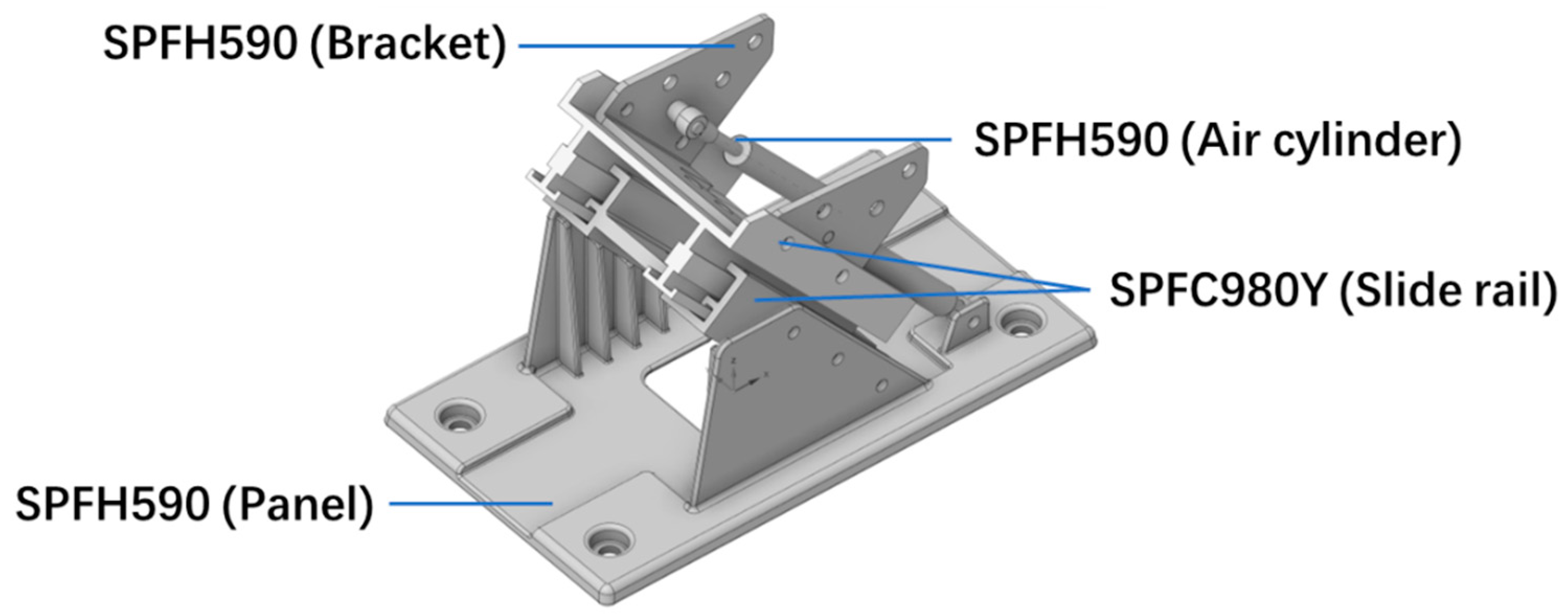
2. Monopost Seat
3. Safety Performance Standard

| Regulation Name | EUR ECE R14 [12] | North America FMVSS 210/207 [13,14] | ||
|---|---|---|---|---|
| Loading angle | 10 ± 5° | 10 ± 5° | ||
| Load | 3-POINT | SHOULDER | 13,500 ± 200 N | 13,345 N |
| LAP | 13,500 ± 200 N | 13,345 N | ||
| Inertial load | Seat weight × 20 | Seat weight × 20 | ||
| Holding time for load | >0.2 s | >10 s | ||
4. Monopost Seat
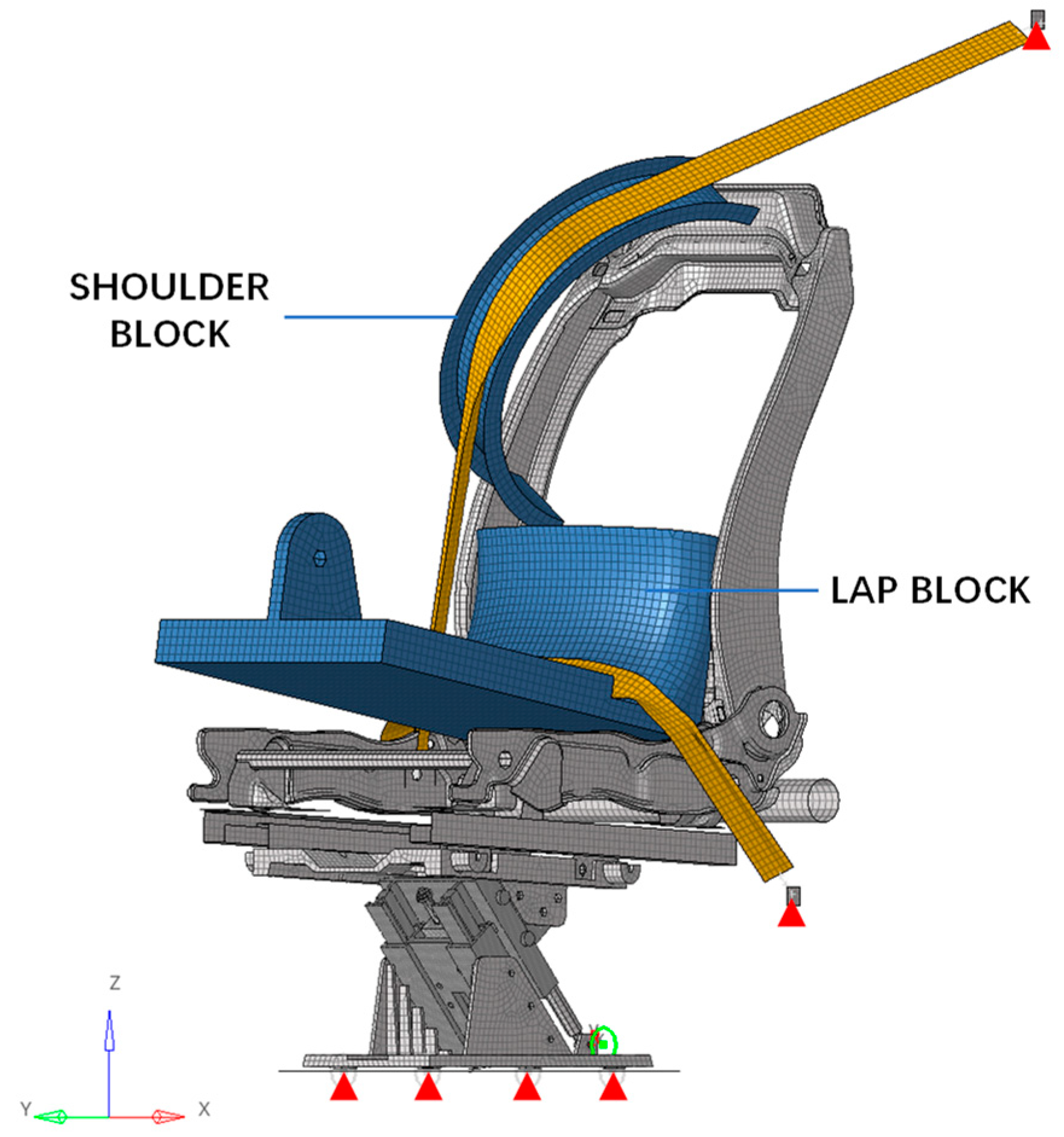
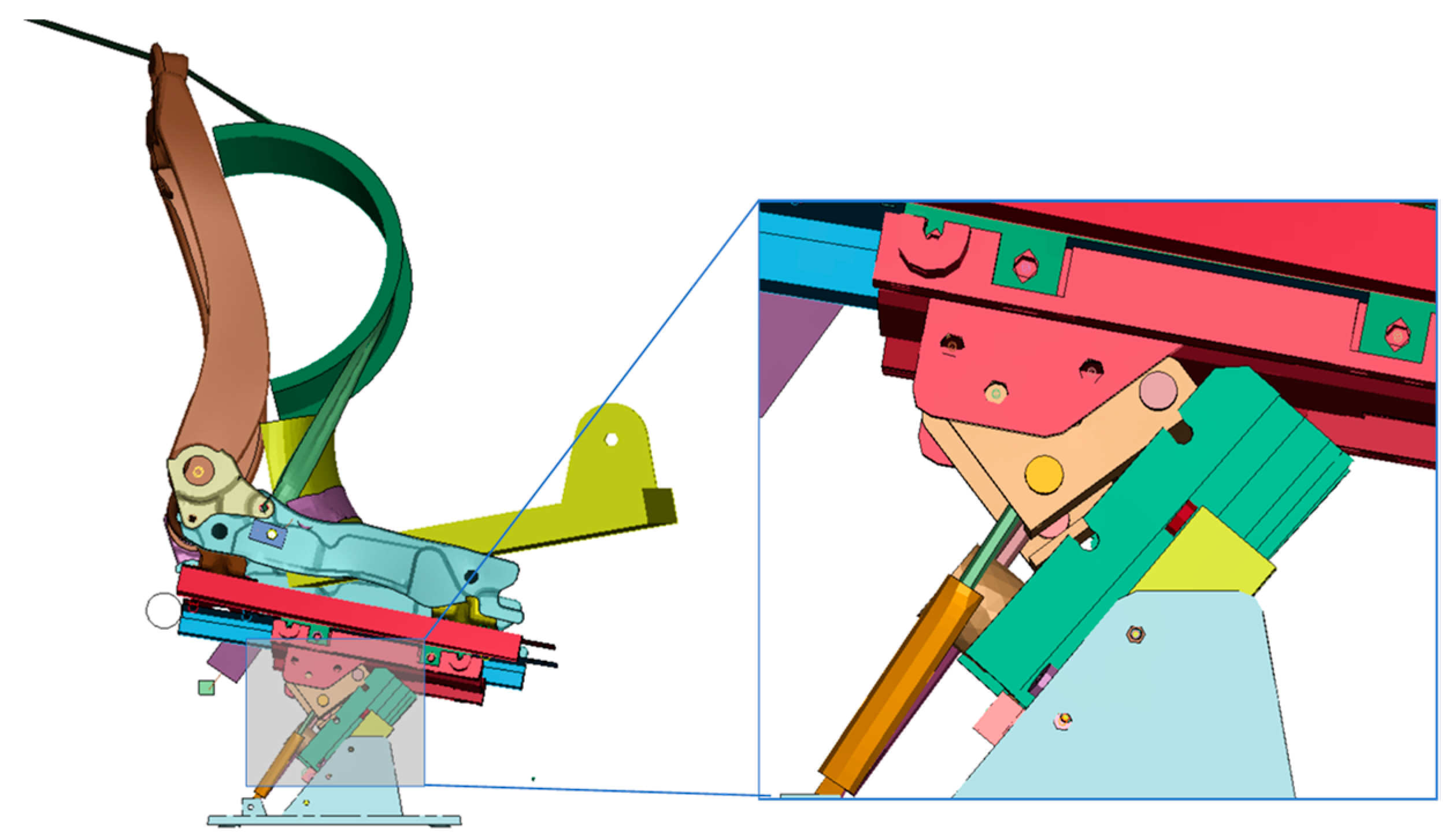
4.1. Dynamic Simulation
4.2. Quasi-Static Simulation
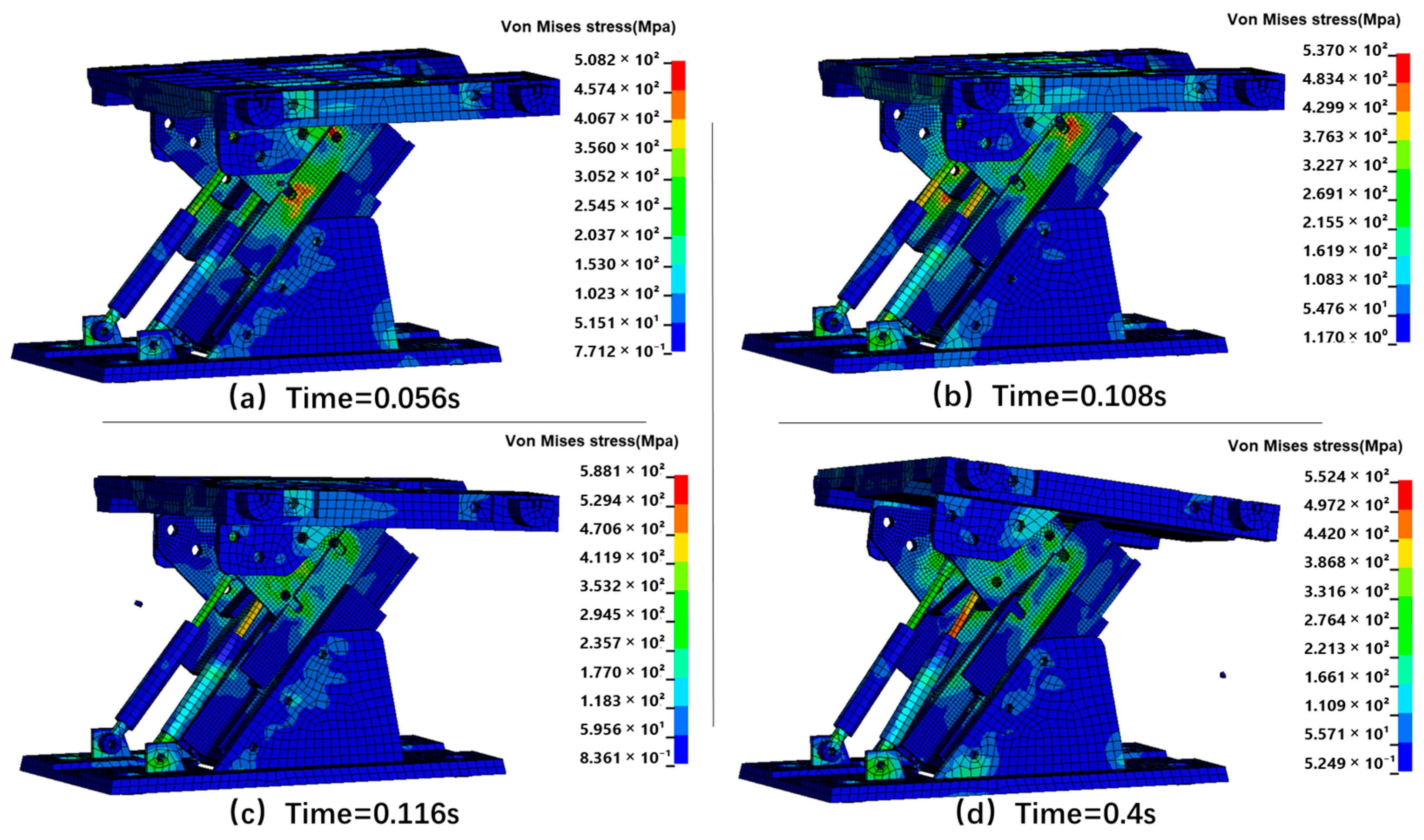
5. Simulation Result
5.1. Dynamics Simulation Result
5.2. Quasi-Static Simulation Result
6. Conclusions
Author Contributions
Funding
Data Availability Statement
Acknowledgments
Conflicts of Interest
References
- Kim, H.; Lee, Y.; Yang, S.; Kang, H.Y. Structural Analysis on Variable Characteristics of Automotive Seat Frame by FEA. Int. J. Precis. Eng. Manuf.-Green Technol. 2016, 3, 75–79. [Google Scholar] [CrossRef]
- National Highway Traffic Safety Administration. Available online: https://www.nhtsa.gov/ (accessed on 1 February 2023).
- Chen, H.; Chen, H.; Wang, L. Analysis of Vehicle Seat and Research on Structure Optimization in Front and Rear Impact. World J. Eng. Technol. 2014, 2, 92–99. [Google Scholar] [CrossRef]
- GB 14167-2013; Safety-Belt Anchorages, ISOFIX Anchorages Systems and ISOFIX Top Tether Anchorages for Vehicles. Standardization Administration of China: Beijing, China, 2013.
- Shi, P.; Wang, S.; Xiao, P. Strength Analysis on Safety-Belt ISOFIX Anchorage for Vehicles Based on HyperWorks and Ls-Dyna. In Proceedings of the Neural Information Processing, Guangzhou, China, 14–18 November 2017; Liu, D., Xie, S., Li, Y., Zhao, D., El-Alfy, E.-S.M., Eds.; Springer International Publishing: Cham, Switzerland, 2017; pp. 387–396. [Google Scholar]
- Deveci, Ö.; Durmuş, A. Otomobil Sürücü Koltuğu Kizak Tasarimi Ve Geliştirilmesi. Uludağ Üniversitesi Mühendislik Fakültesi Derg. 2019, 24, 633–642. [Google Scholar] [CrossRef]
- Deveci, Ö.O.; Durmuş, A. Frontal Impact Sled Testing of a New Designed Vehicle Seat Track Bracket. Int. J. Crashworthiness 2022, 27, 1393–1400. [Google Scholar] [CrossRef]
- Cho, K.-C.; Ha, M.-H.; Moon, H.-J.; Kim, Y.-G. A Study on the Structural Strength Evaluation for the Development of One-ton Grade Commercial Vehicle Seat Frame for the FMVSS 201 Model Kyu-. J. Korean Soc. Manuf. Process Eng. 2018, 17, 130–136. [Google Scholar] [CrossRef]
- Manea, A.M.; Iozsa, M.D.; Stan, C.; Ioniţă, A. Finite Element Analysis for Testing Safety-Belt Anchorages. IOP Conf. Ser. Mater. Sci. Eng. 2022, 1235, 012048. [Google Scholar] [CrossRef]
- Hessenberger, K. Strength Analysis of Seat Belt Anchorage According to ECE R 14 and FMVSS. In Proceedings of the Finite Element Modeling 4th European LS-DYNA Users Conference Crash/Automotive Applications IIB II—15; 2003. Available online: https://api.semanticscholar.org/CorpusID:4943871 (accessed on 1 February 2023).
- EU Position Paper on Test-Case on Functional Equivalence (Proposed Methodology for Automotive Regulatory Equivalence). Available online: https://trade.ec.europa.eu/doclib/docs/2015/january/tradoc_153023.pdf (accessed on 1 February 2023).
- UNECE, Regulation No. 14 Rev.5 Uniform Provisions Concerning the Approval of Vehicles with Regard to Safety-Belt an-chorages, ISOFIX Anchorages Systems and ISOFIX Top Tether Anchorages. 2012. Available online: https://unece.org/transport/vehicle-regulations-wp29/standards/addenda-1958-agreement-regulations-0-20 (accessed on 2 March 2023).
- U.S. Department of Transportation, Seat Belt Assembly Anchorages. National Highway Safety Administration, Federal Motor Vehicle Standard; No. 210; U.S. Department of Transportation: Washington, DC, USA, 1994.
- U.S. Department of Transportation, Seating System, National Highway Safety Administration, Federal Motor Vehicle Standard; No. 207; U.S. Department of Transportation: Washington, DC, USA, 1992.
- Shi, P.; Xu, Z. Analysis of Seat Belt Anchorage Strength for Vehicles. IOP Conf. Ser. Mater. Sci. Eng. 2018, 301, 012127. [Google Scholar] [CrossRef]
- Patil, K.; Reddy, S.; Zafar, N. Optimization of Seatbelt Anchorage Mount Locations for Occupant Injury Reduction in Frontal Crash; SAE International: Warrendale, PA, USA, 2016. [Google Scholar]
- ISO 898-1:2013; Mechanical Properties of Fasteners Made of Carbon Steel and Alloy Steel—Part 1: Bolts, Screws and Studs with Specified Property Classes—Coarse Thread and Fine Pitch Thread. International Organization for Standardization: Geneva, Switzerland, 2013.


| Material | SPFH590 | SPFC980Y |
|---|---|---|
| Density (Mpa) | 7.8 | 7.8 |
| Poisson’s ratio | 0.29 | 0.3 |
| Young’s modulus (Gpa) | 200 | 190 |
| Yield stress (Mpa) | 420 | 490 |
| Tensile strength (Mpa) | 590 | 980 |
| The maximum material plastic strain/Elongation (%) | 22 | 7 |
Disclaimer/Publisher’s Note: The statements, opinions and data contained in all publications are solely those of the individual author(s) and contributor(s) and not of MDPI and/or the editor(s). MDPI and/or the editor(s) disclaim responsibility for any injury to people or property resulting from any ideas, methods, instructions or products referred to in the content. |
© 2023 by the authors. Licensee MDPI, Basel, Switzerland. This article is an open access article distributed under the terms and conditions of the Creative Commons Attribution (CC BY) license (https://creativecommons.org/licenses/by/4.0/).
Share and Cite
Sun, D.; Park, S.; Han, Y.; Kim, J. Verification of Automotive Monopost Seat Strength through Dynamic and Quasi-Static Simulations. Appl. Sci. 2023, 13, 5827. https://doi.org/10.3390/app13105827
Sun D, Park S, Han Y, Kim J. Verification of Automotive Monopost Seat Strength through Dynamic and Quasi-Static Simulations. Applied Sciences. 2023; 13(10):5827. https://doi.org/10.3390/app13105827
Chicago/Turabian StyleSun, Di, Soojin Park, Yongtak Han, and Jinho Kim. 2023. "Verification of Automotive Monopost Seat Strength through Dynamic and Quasi-Static Simulations" Applied Sciences 13, no. 10: 5827. https://doi.org/10.3390/app13105827