1. Introduction
With the increasing development of MEMS technology, microfluidic technology has also been continuously improving. Micropumps are called the heart of microfluidics. They enable micro and precise fluid delivery and, thus, have vital application prospects in various fields, such as biomedicine [
1,
2,
3], cooling systems [
4,
5,
6], fuel supply [
7,
8,
9], and chemical fields [
10,
11,
12].
Most micropumps can be categorized into two groups: mechanical micropumps (with moving parts) and non-mechanical micropumps (without moving parts) [
13]. Micro diaphragm pumps and peristaltic micropumps are the main representatives of the mechanical micropumps. The common principle employs a pump chamber that is closed with a flexible diaphragm on at least one side. Oscillatory movement of the diaphragm generates a two-phase pump cycle with periodic volume changes. The valves act as “fluidic rectifiers” that direct the bidirectional fluid movement generated inside the pump chamber into a desired unidirectional flow [
14].
Piezoelectric driving is the drive mechanism used for different micro pumps, including peristaltic pumps, and it uses the piezoelectric vibrator (piezo-vibrator) as the power source. The inverse piezoelectric effect of piezoelectric ceramics [
15] promotes the periodic deformation of the piezo-vibrator (which manifests as piezo-vibrator vibration on the macroscopic scale) and then changes the volume of the pump chamber to realize fluid pumping. In recent years, the piezoelectric micropump has received increasingly more attention and has become one of the hot spots and focuses of research at home and abroad.
High output performance has always been an important goal of piezoelectric micropump development, which can be achieved through a variety of approaches, such as increasing the number of pump chambers and exploring a variety of pump chamber connection forms (series, parallel, and parallel-series). Zhang [
16] designed a five-chamber series PZT pump with dimensions of 170 mm × 50 mm × 20 mm. The experimental results show that the output pressures of three-chamber, four-chamber, and five-chamber piezoelectric pumps are 39%, 83%, and 128% higher than that of single chamber pump, and the maximum flow rates are 25.9%, 49.2%, and 67.8% higher than that of single chamber pumps. The maximum output flow rate can reach 469.2 mL/min, and the maximum output pressure can reach 16.1 kPa. Vatanabe [
17] proposed a parallel-series configuration for bimorph piezoelectric actuator micropumps. The results show that under the excitation of 60 V, the maximum flow rate of the parallel piezoelectric micropump is 422 mL/min and the maximum pressure is 0.12 kPa, while the maximum flow rate of the series form is 98 mL/min and the maximum pressure is 0.34 kPa. John Valdovinos [
18] reported a low-voltage piezoelectric pump for small hydraulic systems. The pump uses laser-cut spring steel to create a passive globe valve in the shape of four leaves, which has a total volume of 45 cm
3. The test results show that the maximum output flow and pressure reach 186 mL/min and 125 kPa, respectively.
It is evident that these micropumps are basically unable to meet the requirements for high output flow rate, high output pressure, and small size all at the same time. In order to solve the above problems to the maximum extent, based on the series structure, a high-output piezoelectric micropump using the circular unimorph piezo-vibrator and the cantilever check valve is presented in this work. It aims to achieve breakthrough high-output performance of miniaturized piezoelectric pumps with adjustable output flow and output pressure, thus gaining strong practicality in biomedicine, cooling systems, fuel supply, chemical applications, etc.
2. Structure and Working Principle
Single-chamber, double-chamber series, and four-chamber series piezoelectric micropumps are designed in this paper. The multi-chamber series piezoelectric micropump is fabricated on the basis of the structure of the single-chamber micropump.
Figure 1a,b provide exploded views of the single and four-chamber series piezoelectric micropumps, respectively. Specifically, they include the piezo-vibrator, pump body, cantilever valves, inlet, and outlet. There is a limit support at the water outlet of the pump body to change the opening of the valve, and it can also prevent the cantilever valve from deforming too much and losing its performance when it is subjected to large pressure.
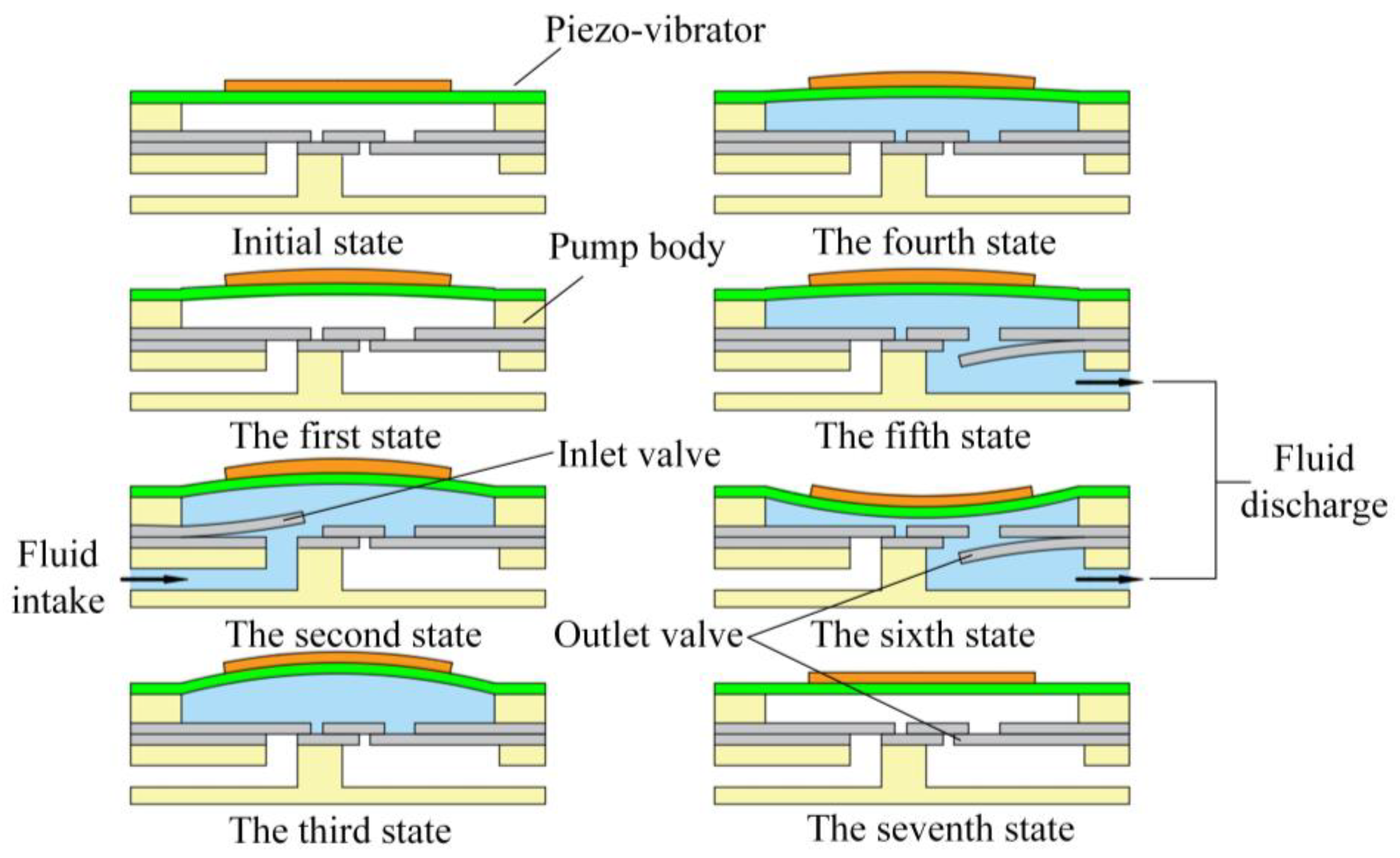
Figure 2 is the working principle diagram of the piezoelectric micropump. When working, the piezoelectric vibrator will generate periodic bending vibration under voltage excitation, together with the valve action, thus forming a unidirectional flow of fluid. Due to the rigidity of the valve, it is necessary to generate negative pressure in the pump chamber to open the valve; the greater the negative pressure, the greater the opening angle of the valve. The critical pressure that makes the valve open is called the valve opening pressure. Generally, the pressure in the pump chamber is set to 0 at the moment of the initial working state.
In detail, at the first stage and the second stage, the piezo-vibrator is bent upward. When the negative pressure in the pump chamber exceeds the opening pressure of the inlet valve, the inlet valve is opened, the outlet valve is closed, and the fluid enters the pump chamber. At this time, the negative pressure in the pump chamber is greater than the opening pressure of the inlet valve to keep it open. At the third and the fourth stage, the piezo-vibrator first bends upward until the limit state and then bends downward until the back pressure is zero. During this time, more and more fluid flows into the pump chamber because the flow in the pump chamber will offset part of the volume. The pump chamber back pressure is less than the valve opening pressure; the inlet valve is completely closed. At this point, the outlet valve is still in the closed state; in the fifth stage and the sixth stage, the piezo-vibrator is bent down to the limit from the position of zero back pressure, and the outlet valve is opened until the end of drainage work; in the seventh stage, the piezo-vibrator is restored to a flat position and the piezoelectric micropump returns to its initial state. From a macro perspective, the fluid forms a continuous unidirectional flow in the pump chamber.
3. The Limit Output Performance of Piezoelectric Micropump
The limit output performance of the piezoelectric micropump refers to the output flow and the corresponding output pressure of the piezoelectric micropump during the ideal vibration process of the piezo-vibrator. The limit output performance can be theoretically estimated based on a formula [
19]. The output flow
of the piezoelectric micropump is
Here, is the number of piezoelectric micropump chambers, is the delay response coefficient of the valve to the piezo-vibrator, is the volume change of the piezoelectric micropump, and is the operating frequency of the piezoelectric micropump.
It is evident from Formula (1) that when the delay response coefficient of the valve to the vibration of piezo-vibrator is constant, the pump chamber number, working frequency, and volume change of the piezoelectric micropump affect the output flow rate of the piezoelectric micropump.
Then, the output pressure
of the piezoelectric micropump is
where
is the fluid density,
is the flow coefficient, and
is the minimum cross-sectional area of the fluid channel.
It is evident from Formula (2) that when the flow coefficient of the piezoelectric micropump is constant, the output flow rate of the piezoelectric micropump, the fluid density, and the minimum cross-sectional area of the fluid channel of the piezoelectric micropump all have an impact on the pressure of the piezoelectric micropump.
4. Fabrication of Prototype and Experimental Scheme
To evaluate the effect of various parameters on the performance of the piezoelectric micropump, the output flow rate and output pressure of the prototype with different parameters were compared. Three sets of test prototypes were used in our experiments, and the average of the three sets of data was used as the experimental data.
Table 1 lists the main structural parameters of the piezoelectric micropump.
PMMA sheets and beryllium bronze are used as raw materials for the pump body and valves, respectively. They are both processed by a precision engraving machine and assembled via a bonding process.
Figure 3a shows the processing sequence of the valve; in order, the valves are cut with a carving machine and then are polished, cleaned, heat treatment, washed, and dried.
Figure 3b is the processing sequence of the pump body, which includes carving, cleaning, drilling, cleaning again, and drying.
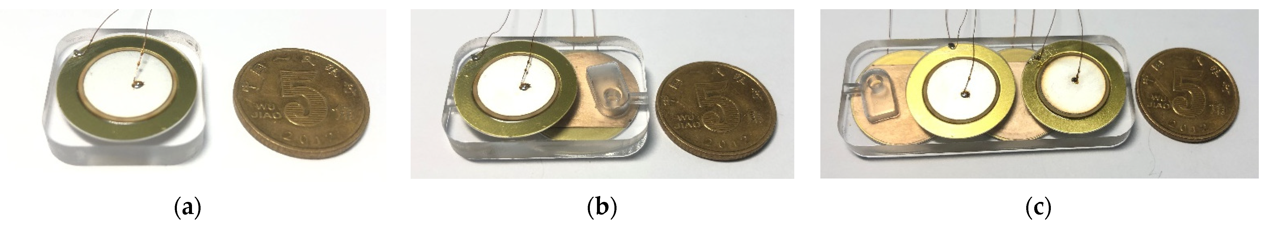
Figure 4a–c are the prototype photos of the single-chamber, double-chamber series, and four-strong series of micropumps, with volumes of 22 mm × 22 mm × 5 mm, 32.6 mm × 22 mm × 5 mm, and 53.8 mm × 22 mm × 5 mm, respectively.
Figure 5 is the experimental platform. The instruments used in the experiment include a signal generator, a power amplifier, and a lifting platform, measuring cylinders of different specifications, beakers, timers, etc.
5. Results and Analysis
According to
Table 2, piezoelectric micropumps with different parameters are fabricated. The following are the test results of piezoelectric micropumps with different parameters:
5.1. Output Performance Test of Single-Chamber Micropumps with Different Valve Openings
The limit support of the outlet of the piezoelectric micropump can change the opening of the valve, thus affecting the performance of the micropump. The piezoelectric micropump without limit support and the single chamber piezoelectric micropump with valve openings of 0.3 mm, 0.4 mm, 0.5 mm, 0.6 mm, and 0.7 mm were fabricated.
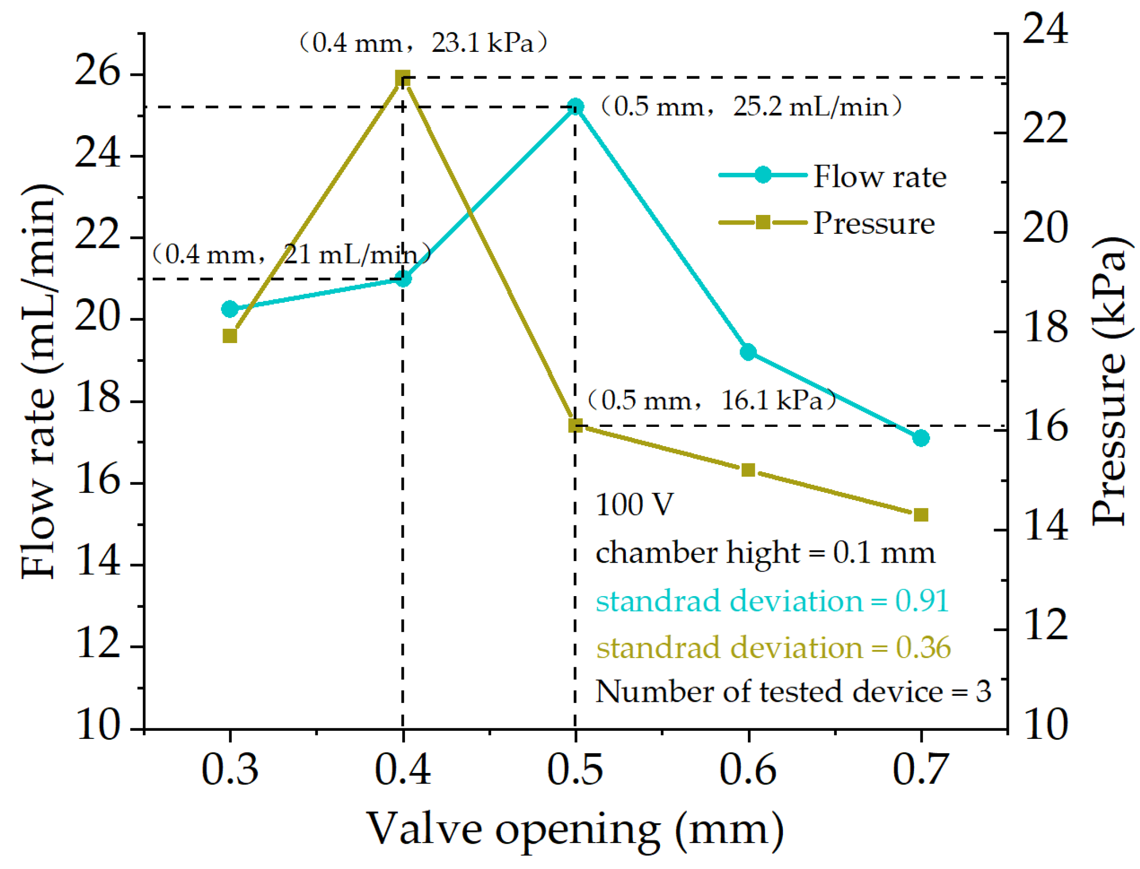
Figure 6 shows their maximum output flow rate and output pressure at 100 V. It is evident that when the valve opening is 0.4 mm, the maximum output pressure of the piezoelectric micropump can reach 23.1 kPa, and the corresponding output flow rate is up to 21 mL/min; when the valve opening is 0.5 mm, the maximum output flow of the piezoelectric micropump is 25.2 mL/min, and the corresponding maximum output pressure is 16.1 kPa; and the maximum output flow of the piezoelectric micropump without limit support is 17.6 mL/min, and the maximum output pressure is 15.4 kPa. It is evident from the comparison that adding limit support at the outlet can improve the output performance of the piezoelectric micropump, especially for the output pressure. This is because the limit support can help the valve to rebound quickly, reducing the leakage of fluid. However, it is evident from
Figure 6 that when the valve opening is 0.3 mm, 0.6 mm, or 0.7 mm, the output performance of the valve is less than that of 0.4 mm and 0.5 mm. This is because too small of a valve opening will hinder the movement of the valve and affect the flow efficiency of the fluid and too large of a valve opening has a negative impact on the rebound speed of the valve, which will cause fluid leakage and affect the output performance of the piezoelectric micropump. Compare the output flow rate and output pressure of the piezoelectric micropump with valve openings of 0.4 mm and 0.5 mm: when the valve opening is 0.4 mm, the output flow rate and output pressure are 83% and 140% of the 0.5 mm one, respectively. When the valve opening is 0.4 mm, the output flow rate of the micropump is slightly smaller, but it has an excellent output pressure. Therefore, we set the valve opening to 0.4 mm.
5.2. Output Performance Test of Single-Chamber Micropumps with Different Pump Chamber Heights
Piezoelectric micropumps with pump chamber heights of 0.02 mm, 0.05 mm, 0.1 mm, 0.15 mm, 0.2 mm, and 0.25 mm were tested.
Figure 7 is the maximum output performance of the piezoelectric micropump with different chamber heights under a certain voltage. It is evident that the output flow rate and output pressure of the piezoelectric micropump both increase first and then decrease with the increase in the chamber height. This is because if the height of the pump chamber is too small, the valve will touch the piezo-vibrator during the movement, which will hinder the movement of the valve and affects the fluid outflow efficiency. However, when the height of the pump chamber is too great, the dead volume will be significantly increased, which will reduce the output performance of the piezoelectric micropump. In this paper, when the height of the pump chamber is 0.1 mm, the maximum output flow of the micropump is 21 mL/min, and its output pressure is 23.1 kPa; when the height of the pump chamber is 0.15 mm, its maximum output pressure is 24.3 kPa, and the output flow rate is 14.5 mL/min. When the chamber height is 0.1 mm, the output flow rate and output pressures are 145% and 95% of the 0.15 mm one, respectively. The output flow rate of the piezoelectric micropump with a pump chamber height of 0.1 mm is much larger than that of 0.15 mm, and its output pressure is almost the same as the 0.15 mm one. Therefore, we set the pump chamber height of the piezoelectric micropump to 0.1 mm.
5.3. Output Performance Test of Multi-Chamber Series Piezoelectric Micropump
Figure 8 shows the relationship between the limit output performance and frequency of the multi-chamber series piezoelectric micropump under 100 V. It is evident that the limit output performance of the dual-chamber micropump and the four-chamber micropump show a trend of first increasing and then decreasing with the increase of frequency, while the optimal operating frequency of the dual-chamber micropump is lower than that of the four-chamber micropump. This is because the response characteristics of the piezoelectric micropump under working conditions have changed, thus affecting the outflow efficiency of the inlet and outlet of the micropump. For a dual-chamber series piezoelectric micropump, when the frequency is 120 Hz, the limit output flow is 37 mL/min; when the frequency is 100 Hz, the limit output pressure is 43.7 kPa. For a four-chamber series piezoelectric micropump, when the frequency is 450 Hz, the limit output flow rate reaches 62.5 mL/min; when the frequency is 550 Hz, the optimal output pressure exceeds 100 kPa.
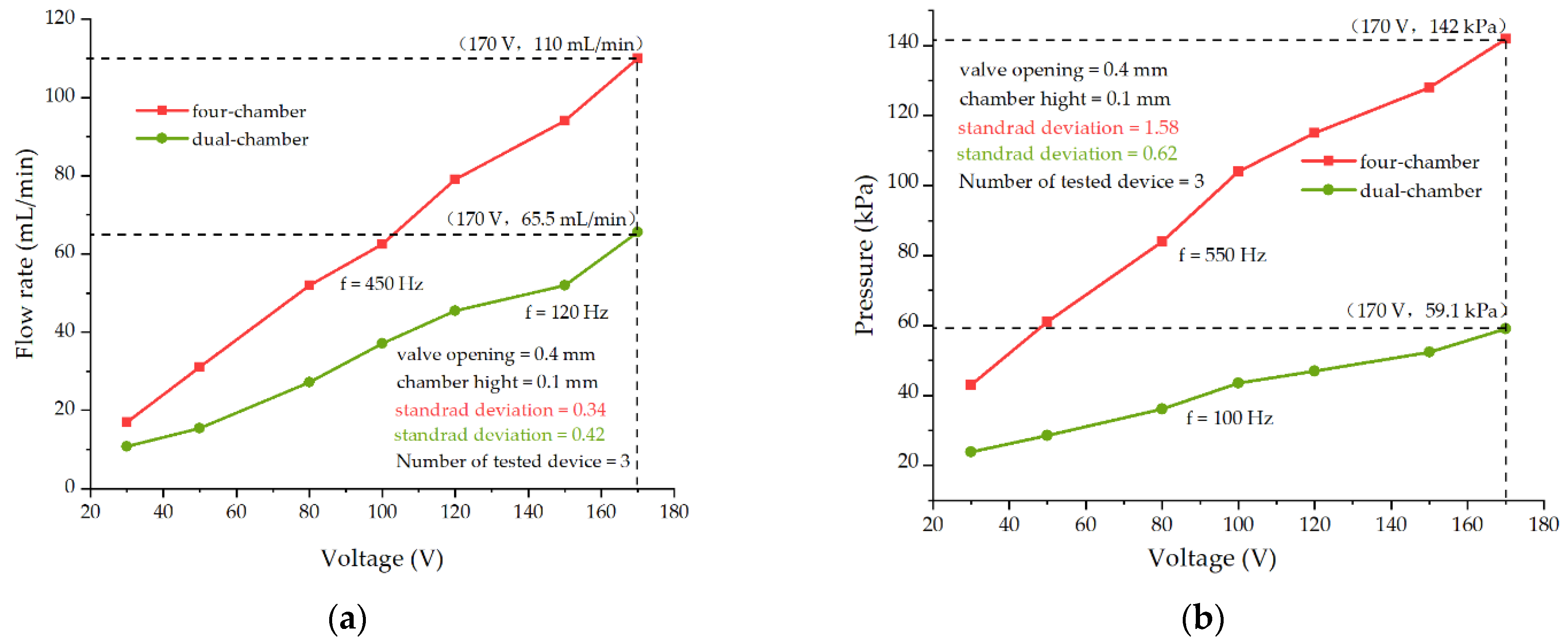
Figure 9 provides the relationship between the limit output performance of the multi-chamber series piezoelectric micropump and the voltage. It is evident that when the frequency is constant, the limit output performance of the multi-chamber series piezoelectric micropump increases with the increase in the voltage and has a good linear relationship. For the dual-chamber series piezoelectric micropump, when the voltage is constant at 170 V, the output flow rate is 65.5 mL/min at 120 Hz, and the output pressure can reach 59.1 kPa at 100 Hz. For the four-chamber series piezoelectric micropump, when the voltage is constant at 170 V, the output flow reaches 110 mL/min at 450 Hz, and the output pressure can reach 142 kPa at 550 Hz. Under the same voltage, the output flow rate of the four-chamber series micropump is about 1.6 times that of the double-chamber series micropump, and the output pressure is about 2.4 times that of double-chamber series one.
Next,
Table 2 provides the output performance of single-, dual-, and four-chamber micropumps under 100 V. The output flow rate of the four-chamber micropump is about 1.69 times that of the double-chamber micropump and 2.97 times that of the single-chamber micropump; its output pressure is about 2.39 times of double-chamber micropump and 4.5 times of the single-chamber micropump. The output flow rate of the double-chamber micropump is about 1.73 times that of the single-chamber micropump, and the output pressure is about 1.88 times that of the single-chamber micropump.
Furthermore,
Table 3 shows a comparison of the technical reports of piezoelectric micropumps. It is evident that the piezoelectric micropumps reported in these studies are lacking in output performance or overall size. The piezoelectric micropump proposed in this work makes up for the deficiency to the maximum extent, i.e., both high output performance and miniaturization. Therefore, this work promotes the development of piezoelectric micropumps with high output performance.
6. Conclusions
Based on the single-chamber micropump, a series of multi-chamber series piezoelectric micropumps is proposed. After analyzing the working principle, the piezoelectric micropump prototypes with different parameters were fabricated for testing, and finally, the experimental conclusions were drawn. The specific conclusions are as follows:
We conclude that the valve opening and pump chamber height will affect the output performance of piezoelectric micropump. Too small of a valve opening is detrimental to the opening of the valve, affecting the flow efficiency of the fluid, and too of a large valve opening is not conducive to the rebound of the valve, which will cause fluid leakage and affect the output performance of the micropump. Proper valve opening will improve the rebound speed of the valve and prevent the valve from failing due to over-opening. Too small of a pump chamber height will hinder the movement of the valve and too large of a pump chamber height will increase dead volume, thus affecting the performance of the piezoelectric micropump. After a great deal of experimental research, this paper found that when the valve opening is 0.4 mm and the pump chamber height is 0.1 mm, the comprehensive output performance of the piezoelectric micropump is the best.
The piezoelectric micropump in this study can achieve high output performance under the condition of small size, and the performance of the multi-chamber micropump is better than that of the single-chamber micropump. The double-chamber series micropump has a maximum output flow rate at 120 Hz and a maximum output pressure at 100 Hz, while the four-chamber series micropump has a maximum output flow rate at 450 Hz and a maximum output pressure at 550 Hz. It is evident that the best frequency for the output flow rate and output pressure is different, so the frequency with the best comprehensive performance can be selected to drive the piezoelectric micropump. The frequency of the output flow rate and pressure of the four-chamber series micropump is higher than that of the double-chamber series piezoelectric micropump. This is because the response characteristics of the piezoelectric micropump in resonance state change, which affects the outflow efficiency of the micropump inlet and outlet.
Under the same voltage, the output flow rate of the four-chamber micropump is about 1.69 times that of the double-chamber micropump and 2.97 times that of the single-chamber micropump, and its output pressure is about 2.39 times that of the double-chamber micropump and 4.5 times the single-chamber micropump. The output flow rate of the double-chamber micropump is about 1.73 times that of the single-chamber micropump, and the output pressure is about 1.88 times that of the single-chamber micropump. This shows that the multi-chamber series piezoelectric micropump can effectively improve the output performance of the piezoelectric micropump, especially for the output pressure of the piezoelectric micropump. That is, the multi-chamber series micropump can obtain higher output performance under lower operating conditions, which is more conducive to practical applications.
Author Contributions
Conceptualization, X.L. (Xiaopeng Liu); methodology, X.L. (Xiaopeng Liu); software, X.L. (Xiaopeng Liu); validation, X.L. (Xiaopeng Liu), X.L. (Xingqi Li), M.W. and S.C.; formal analysis, X.L. (Xiaopeng Liu); investigation, X.L. (Xiaopeng Liu) and X.W.; resources, X.L. (Xiaopeng Liu); data curation, X.L. (Xiaopeng Liu); writing—original draft preparation, X.L. (Xiaopeng Liu); writing—review and editing, X.L. (Xiaopeng Liu) and G.L.; visualization, X.L. (Xiaopeng Liu); supervision, X.L. (Xiaopeng Liu); project administration, G.L.; funding acquisition, G.L. All authors have read and agreed to the published version of the manuscript.
Funding
This research was funded by Jilin Province Natural Science Foundation Projects, grant number 20170101136JC, and by National Natural Science Foundation Projects, grant numbers 51375207 and 51875234.
Institutional Review Board Statement
Not applicable.
Informed Consent Statement
Not applicable.
Data Availability Statement
Not applicable.
Conflicts of Interest
The authors declare no conflict of interest.
References
- Cui, Q.; Liu, C.; Zha, X.F. Simulation and optimization of a piezoelectric micropump for medical applications. Int. J. Adv. Manuf. Technol. 2006, 36, 516–524. [Google Scholar] [CrossRef]
- Kaçar, A.; Özer, M.B.; Taşcıoğlu, Y. A Novel Artificial Pancreas: Energy Efficient Valveless Piezoelectric Actuated Closed-Loop Insulin Pump for T1DM. Appl. Sci. 2020, 10, 5294. [Google Scholar] [CrossRef]
- Luo, W.F.; Chen, R.H.; Ma, H.K. Concept of the Partial Throw-Away Design of Piezoelectric Micropump for Medical Uses with Low Cost and Waste. Appl. Mech. Mater. 2013, 477–478, 363–367. [Google Scholar] [CrossRef]
- Davis, L.P.; Pires, R.F.; Henderson, B.K.; Vatanabe, S.L.; de Oliveira, A.R.; McMickell, M.B.; Nakasone, P.H.; Silva, E.C. Water cooling system using a piezoelectrically actuated flow pump for a medical headlight system. In Industrial and Commercial Applications of Smart Structures Technologies 2007; SPIE: Bellingham, WA, USA, 2007; Volume 6527, p. 65270. [Google Scholar]
- Yueh, W.; Wan, Z.; Xiao, H.; Yalamanchili, S.; Joshi, Y.; Mukhopadhyay, S. Active Fluidic Cooling on Energy Constrained System-on-Chip Systems. IEEE Trans. Compon. Packag. Manuf. Technol. 2017, 7, 1813–1822. [Google Scholar] [CrossRef]
- Huang, J.; Zou, L.; Li, Z.; Wang, X.; Zhang, Q.; Wang, Y. Development and performance comparison of valveless piezoelectric pumps with asymmetrical channels. Sens. Actuators A 2020, 314, 112241. [Google Scholar] [CrossRef]
- Park, J.H.; Seo, M.Y.; Ham, Y.B.; Yun, S.N.; Kim, D.I. A study on high-output piezoelectric micropumps for application in DMFC. J. Electroceram. 2012, 30, 102–107. [Google Scholar] [CrossRef]
- Wang, J.; Zhao, X.; Chen, X.; Yang, H. A Piezoelectric Resonance Pump Based on a Flexible Support. Micromachines 2019, 10, 169. [Google Scholar] [CrossRef] [Green Version]
- Hwang, J.Y.; Shin, K.Y.; Lee, S.H.; Kang, K.; Kang, H.; Lee, J.H.; Peck, D.H.; Jung, D.H.; Jang, J.H. Periodic fuel supply to a micro-DMFC using a piezoelectric linear actuator. J. Micromech. Microeng. 2010, 20, 085023. [Google Scholar] [CrossRef]
- Ma, T.; Sun, S.; Li, B.; Chu, J. Piezoelectric peristaltic micropump integrated on a microfluidic chip. Sens. Actuators A 2019, 292, 90–96. [Google Scholar] [CrossRef]
- Tanaka, Y. A Peristaltic Pump Integrated on a 100% Glass Microchip Using Computer Controlled Piezoelectric Actuators. Micromachines 2014, 5, 289–299. [Google Scholar] [CrossRef]
- Li, H.; Liu, J.; Li, K.; Liu, Y. A review of recent studies on piezoelectric pumps and their applications. Mech. Syst. Sig. Process. 2021, 151, 107393. [Google Scholar] [CrossRef]
- Forouzandeh, F.; Alfadhel, A.; Arevalo, A.; Borkholder, D.A. A review of peristaltic micropumps. Sens. Actuators A Phys. 2021, 326, 112602. [Google Scholar] [CrossRef] [PubMed]
- Woias, P. Micropumps—Past, progress and future prospects. Sens. Actuators B 2005, 105, 28–38. [Google Scholar] [CrossRef]
- Chure, M.C.; Wu, L.; Wu, K.K.; Lin, Y.C.; Wu, M.J.; Tung, C.C.; Lin, J.S.; Ma, W.C. Effect of Dimensional Size on the Electrical Voltage Generation Property of PZT Piezoelectric Ceramic. Appl. Mech. Mater. 2013, 377, 166–170. [Google Scholar] [CrossRef]
- Zhang, Z.; Kan, J.; Wang, S.; Wang, H.; Ma, J.; Jiang, Y. Effects of driving mode on the performance of multiple-chamber piezoelectric pumps with multiple actuators. Chin. J. Mech. Eng. 2015, 28, 954–963. [Google Scholar] [CrossRef]
- Vatanabe, S.L.; Choi, A.; de Lima, C.R.; Nelli Silva, E.C. Design and Characterization of a Biomimetic Piezoelectric Pump Inspired on Group Fish Swimming Effect. J. Intell. Mater. Syst. Struct. 2009, 21, 133–147. [Google Scholar] [CrossRef]
- Valdovinos, J.; Carman, G.P. Development of a low-voltage piezohydraulic pump for compact hydraulic systems. Smart Mater. Struct. 2015, 24, 125008. [Google Scholar] [CrossRef]
- Peng, T.; Guo, Q.; Yang, J.; Xiao, J.; Wang, H.; Lou, Y.; Liang, X. A high-flow, self-filling piezoelectric pump driven by hybrid connected multiple chambers with umbrella-shaped valves. Sens. Actuators B 2019, 301, 126961. [Google Scholar] [CrossRef]
- Dong, J.S.; Liu, R.G.; Liu, W.S.; Chen, Q.Q.; Yang, Y.; Wu, Y.; Yang, Z.G.; Lin, B.S. Design of a piezoelectric pump with dual vibrators. Sens. Actuators A 2017, 257, 165–172. [Google Scholar] [CrossRef]
- Zeng, P.; Li, L.A.; Dong, J.; Cheng, G.; Kan, J.; Xu, F. Structure design and experimental study on single-bimorph double-acting check-valve piezoelectric pump. Proc. Inst. Mech. Eng. Part C J. Mech. Eng. Sci. 2015, 230, 2339–2344. [Google Scholar] [CrossRef]
- Chen, J.; Huang, D.; Feng, Z.H. A U-shaped piezoelectric resonator for a compact and high-performance pump system. Smart Mater. Struct. 2015, 24, 105009. [Google Scholar] [CrossRef]
| Publisher’s Note: MDPI stays neutral with regard to jurisdictional claims in published maps and institutional affiliations. |
© 2022 by the authors. Licensee MDPI, Basel, Switzerland. This article is an open access article distributed under the terms and conditions of the Creative Commons Attribution (CC BY) license (https://creativecommons.org/licenses/by/4.0/).


