Article

Research on Speed and Acceleration of Hand Movements as Command Signals for Anthropomorphic Manipulators as a Master-Slave System

Faculty of Mechanical Engineering, Military University of Technology, 00-908 Warsaw, Poland
*
Author to whom correspondence should be addressed.
Appl. Sci. 2022, 12(8), 3863; https://doi.org/10.3390/app12083863
Submission received: 22 February 2022 / Revised: 6 April 2022 / Accepted: 7 April 2022 / Published: 11 April 2022
(This article belongs to the Special Issue State-of-the-Art in Human Factors and Interaction Design)

Abstract

:
Due to threats to human safety, remotely controlled manipulators are more and more often used to carry out rescue tasks in hazardous zones. To ensure high efficiency and productivity of their work, intuitive control systems are necessary, e.g., master-slave and drive systems that maximize the speed of working movements by copying the movements of the operator’s hands and are adapted to human perception and capabilities. Proper design of manipulator drive and control systems, therefore, requires knowledge of the acceleration and velocity of hand movements as signals controlling manipulators. This paper presents the results of tests of speed and acceleration in the implementation of the hand when making precise movements and moving objects over short distances (0.4–0.5 m) and during relatively long-distance reaching movements (0.73–0.93 m). Research has shown that, at short distances, the hand movements do not reach the maximum speed, while at longer distances, there is a period of constant maximal speed. In addition, studies have shown that the maximum speed of manipulation movements (longitudinal, lateral, and vertical) does not depend on the direction of movement. Moreover, precise movements were performed at a much slower velocity than reaching movements.

1. Introduction

Military, nuclear, biological, chemical, and environmental threats (e.g., noise, vibration, temperature) have resulted in a growing interest in manipulators for intervention activities in recent years, performing tasks in the conditions of teleoperation. IED (Improved Explosive Device) threats and the disaster in Fukushima demonstrated the need to have robots equipped with such manipulators, capable of quick interventions in unfavorable conditions. Due to the threats, robots should quickly remove obstacles to the side using manipulators (in this case, high precision of movement is not required) and carry out reconnaissance and precise interventions consisting in picking up delicate objects, opening doors, turning devices or installations on and off, etc.
Achieving high efficiency requires, in addition to a very good environmental imaging system to ensure a high level of situational and actional awareness, an intuitive control system that reduces operator training time and increases the speed of work movements.
The joystick control systems for manipulators commonly used in such robots are not very intuitive, they require extensive training to develop appropriate habits and may limit the effectiveness of robots under stressful conditions. For these reasons, the number of degrees of freedom of manipulators is limited in intervention robots—for example, the manipulator of the Talon MK IV robot has only 4 DOF. Master–slave systems controlled by hand movements (Figure 1) are definitely a better solution because they use the natural and previously acquired skills, habits, and reflexes of the operator. This allows one to increase the speed of movements of the manipulator and its effectors to values limited by the operator’s perception (the ability to recognize situations, assess threats, and generate control signals while maintaining safety requirements). Moreover, they enable the use of more dexterity manipulators, e.g., anthropomorphic or redundant ones—without increasing the control problems. Time delay in the case of intervention robots is not a big problem, because in well-designed remote control and teleoperation systems, the delays do not exceed 0.1 s.
Proper design of manipulators controlled in this way requires knowledge of their dynamic and control signal in the form of velocity and acceleration of hand movement.
Research related to the broadly understood dynamics of manipulator operation and their control is currently the subject of interest for many scientists [1,2,3,4,5]. Particular attention has been given to anthropomorphic manipulators [6,7,8,9,10] and redundant manipulators [11,12,13] because these constructions have a very high potential for use in areas requiring the implementation of unique movements changing over time and subject to human decisions and control. The conducted research concerns their application in space missions [14,15,16,17], underwater [4,18], surgery [10,19,20], telerobotic in medicine [21] and rehabilitation [22,23,24,25,26,27,28,29,30,31,32]. Many works also concern research on the cooperation of such manipulators and factors that have a decisive impact on their effectiveness [1,33,34,35,36,37,38].
To ensure the efficiency of such tasks, various control systems are used by intervention manipulators, which are controlled by people. The simplest systems use various types of joysticks and game-pads that allow you to control the movements of individual parts of the manipulator [39,40,41]. However, such solutions are not very intuitive and require long-term training in order to acquire appropriate habits and reflexes [39,42,43,44,45,46]. In order to eliminate these drawbacks and provide more intuitive control, systems using spherical motion generation controllers [47,48,49,50,51], master–slave tracking control systems [52,53,54,55,56], feedback force [57,58,59,60,61,62,63,64,65,66,67], adaptive control systems [68,69,70,71], and systems based on neutron networks and elements of fuzzy logic [71,72,73,74] can be used. Previous research mainly concerns the obtained work dynamics [5,17,75], the accuracy of the effector tracking [4,33,53], errors in the obtained effector trajectory [5,35,36], effector vibrations [75], limitations of the power demand of drive systems with the use of various methods and ways of regulating the examined parameters [75,76,77], and the stability and transparency of systems [64,74,78]. However, there is no information about the actual values of the inputs that should be introduced into the control system to perform tasks by rescue or casting manipulators. These manipulators are characterized by large ranges, lifting capacities, and high inertia forces during operation.
The most common intuitive control is to track the location of the characteristic points of the shoulder, elbow, and wrist [52,53], or the hand itself [10,54,79]. In the first case, all parts of the manipulator repeat hand movements, while in the second, only the effector is given the movement parameters, and the remaining parts of the manipulator adjust their position on the basis of established algorithms. This method is also used to control redundant manipulators [8,9,80]. Depending on the size of the controlled manipulator and its work area and the range of used hand movement, the measured displacements may be multiplied or reduced in order to ensure the intuitiveness of the control room and high work efficiency [81,82]. The control signals can also be modified in order to increase the accuracy of the manipulator’s movement or to limit the dynamic loads [11,12].
To ensure the high efficiency of the manipulators, it is necessary to provide them with the highest possible speed of movement. The perception and the ability to carry out human movements should be the limitations. Therefore, designing an appropriate manipulator control system and ensuring high work efficiency requires knowledge of the control signals that can be generated by a human hand. Therefore, it is necessary to know the maximum speed of movement of hands in different directions and occurring accelerations. This will allow for the proper shaping of the manipulator drive and control.
The studies of the dynamics of the human hand usually concern the kinematic structure, trajectory of movement, and problems in tracking the position and mathematical description of the dynamics of its operation by equations [83,84,85]. There is a lack of information on the actual hand speeds and accelerations occurring during manipulation, which should inform the control systems used in manipulators in a master–slave tracking control system. It should be noted that these may vary depending on the activities carried out. The reaching movements are usually faster, while the precise movements require lower speeds.
In order to better understand the dynamic processes taking place during the control of manipulators in a master–slave system, research was carried out to determine the speed and acceleration of the human hand during reaching movements and precise movements. It is expected that, thanks to the appropriate design of the drive and control system, the manipulator’s foundry and salvage will be able to copy reaching movements of the human hand and slower movements requiring high precision, providing the operator with a sense of full and conscious control of the manipulator [85].
Most of the conducted research concerns the possibility of increasing the precision of manipulators’ movements in conditions of limited data transmission and large time delays. In these studies, waveforms representing relatively slow movements with a limited range are most often used as control signals. Conducting effective rescue operations in areas of destruction and catastrophes requires the ability to implement not only precise movements but also fast, long-range movements in the entire manipulator’s field of operation. Similar requirements apply to, e.g., foundry manipulators, segregation manipulators, or mining manipulators for crushing boulders that are too large. The development of new 5G data transmission technologies indicates the possibility of significantly reducing problems with data transmission [86,87,88,89,90,91]. Therefore, there is a need to know the control signals that can be generated by a human while controlling manipulators in hazardous areas. Their knowledge will allow for proper design of drive systems (achieving the expected speeds of movements), control of rescue manipulators (ensuring the expected precision and stability of movement), and defining the existing dynamic loads of the manipulator structure.
Analyzing the real inputs from human hand movements to the control system, the following null hypotheses were also adopted:
  • Speeds of human hand movements, as inputs introduced into the manipulator control system, strongly depend on the direction of movement (longitudinal, lateral, and vertical)—there are significant differences between speed and direction of movement, which significantly affects the design of the drive system and manipulator control system, and different control procedures are necessary depending on the direction of movement.
  • The maximum speeds of human hand movements during the execution of delivery and precision tasks, which are to be copied in real time by intervention manipulators, do not differ significantly.

2. Methodology

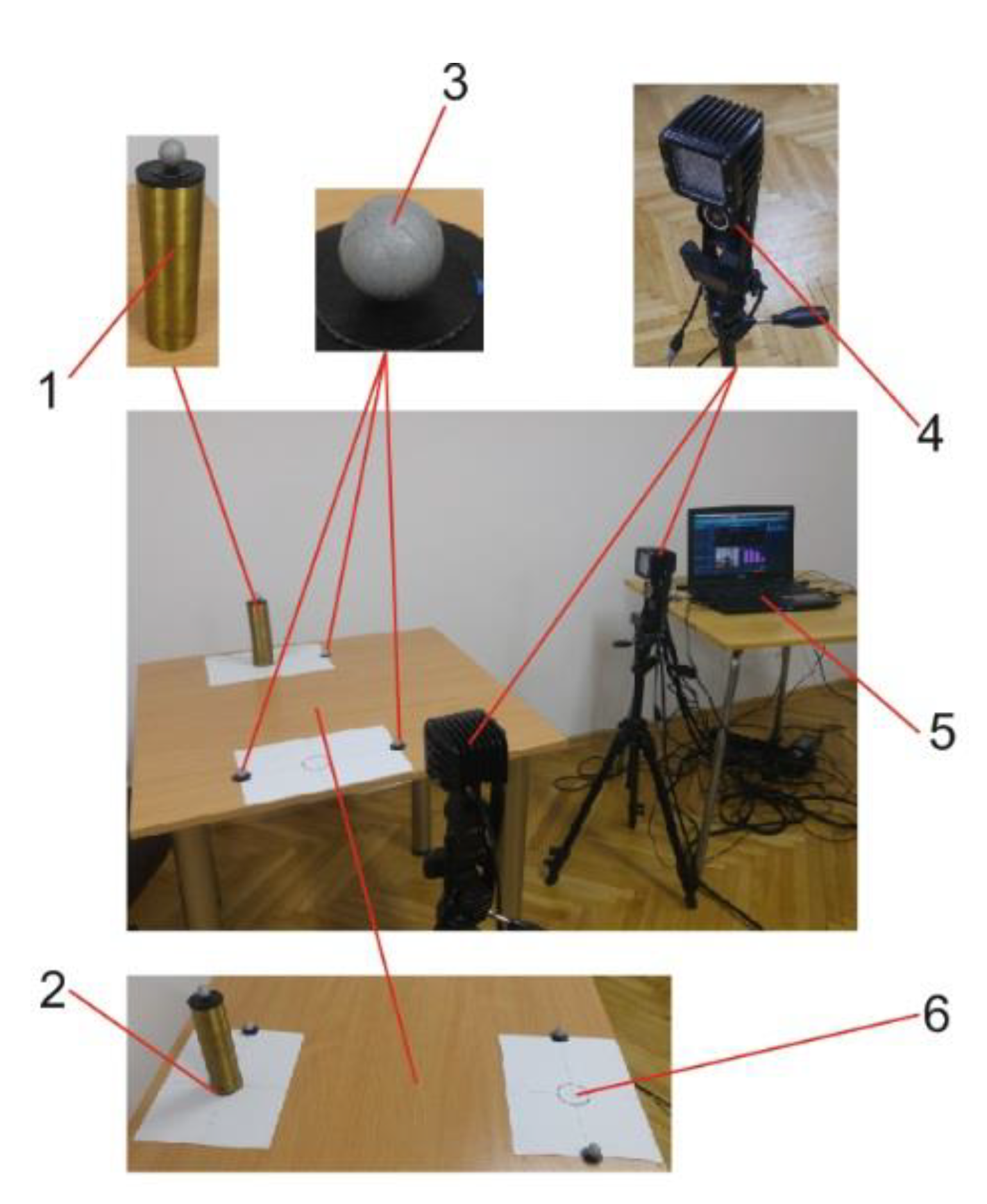
2.1. Experimental Setting and User Task

The primary purpose of the research was to learn about the mean maximum velocity and mean maximum acceleration of human hand movement during the implementation of manipulation tasks and the influence of the direction of movement on the achieved speeds and accelerations.
The study was divided into two stages. The first stage concerned the analysis of the reaching movements, which did not require high precision of the final position. They were made in three directions—longitudinal, lateral, and vertical—and were rectilinear movements. In the second stage, the hand movement during a task requiring precision and obtaining the required accuracy when moving the object between designated areas was examined.
All subjects performed reaching and precise movements with their dominant hand. Each subject performed trials with four reaching movements for each. Therefore, the number of recorded, reaching movements was 360 (30 subjects × 4 movements × 3 directions), and for precise movements, it was 150 (30 subjects × 5 movements × 1 direction). This test was measured after two practice trials.
The operator’s task during the study of reaching movements was to move the handle ((2) in Figure 2) from the adopted initial position to the fixed end position, defined by flexible bumpers mounted on the guides. The operator’s task was to make a one-way movement and return to the position close to the initial position, with a normal hand movement speed. For each type of movement, the position of the guides (3) and bumpers (5) (Figure 2) was changed. Due to the ergonomics of hand movements [92,93], it was assumed that the distance between the bumpers for longitudinal movement (xi) is 430 mm, for transverse (yi) it is 730 mm, and for vertical (zi) it is 930 mm (Figure 2). The basic measuring element of the test stand was a linear encoder with a measuring range of 0–1.25 m and an accuracy of 0.625 mm [94].
During the study of precise movements, the operator’s task was to transfer the cylinder from circle A to circle B (Figure 3). The distance between the centers of the circles was 500 mm. The circle in which the object should be placed was equal to its diameter. For displacement measurement, the position of optical markers (3) was recorded by stereovision cameras ((4) in Figure 4). The displacement in the two axes was recorded so that it was possible to assess the correctness and accuracy of putting down the object.
The basic measuring elements of the test stand based on the MyoVideo (Noraxon U.S.A. Inc., Scottsdale, AZ, USA) system were two stereovision cameras with a horizontal field of view of 57.5°, a vertical field of view of 43.1°, and an accuracy of less than 0.1 mm [95]. To assess the accuracy of the task, it was assumed that the error of putting the object down should not exceed 2 mm on both the x and y axes. The value of the setdown error corresponded to 5% of the diameter of the transferred object.

2.2. Participants

Two-step testing of speed and acceleration of movement of a human hand was carried out in a group of 30 people (male) aged 21 to 37 years and with a height of 165–194 cm. The most numerous groups of respondents (22 people) were students aged 21–22. Five of these volunteers were left-handed.

2.3. Statistical Analyses

The values of velocity and acceleration of the human hand for both types of tests were determined based on the backward differential quotient. The relationship that us allows to determine the speed takes the form [96,97]:
n ˙ i t = n i t n i 1 t t i t i 1 ,
where ni, the displacement depending on the type of motion carried, was xn for the precise transport task, xi for longitudinal movement, yi for lateral movement, and zi for vertical movement; t i is the time corresponding to the movement ni. The acceleration was calculated via the following equation [96,97]:
n ¨ i t = n ˙ i t n ˙ i 1 t t i t i 1 = n i t 2 n i 1 t + n i 2 t t i t i 1 2 .
In order to determine the level of variability of the values of velocity and accelerations of the human hand depending on the operator who carries out the movement, the standard deviation σ was determined and the coefficient of variation Cv. Standard deviation was determined using the following equation [98,99,100]:
σ = i = 1 n μ i μ ¯ 2 n 1 ,
where μ i is the successive values of a given random variable in the sample, μ ¯ is the arithmetic mean of the sample, n is the number of elements in the sample. The coefficient of variation C v was determined from the following equation [98,99,100]:
C v = σ μ ¯ · 100 % .  
As part of the statistical analysis, we checked whether the obtained test results have a similar distribution to the norm and determined the test power. In order to test the normality of the distribution, the Shapiro–Wilk test was performed. The parameters given in the analysis of the normality of the distribution included the maximum velocities and RMS velocities as well as the maximum accelerations, and the RMS acceleration in the subsequent phases of the hand movement for all the carried tests. In performance research, there are backward and outward movements. In precision movement, only the movement to the target can be distinguished. Each of the movements can be divided into phases related to acceleration, steady motion, and deceleration, which are characterized by different values of speed and acceleration.

3. Results

The obtained results of the Shapiro–Wilk test [101] indicate that the distribution of the obtained test results is close to normal. The results of the ANOVA [102] power analysis (for α = 0.05; RMSSE (Root Mean Square Standardized Effect) is 0.566) indicate that the number of trials is sufficient to show whether there are significant differences in the speeds of reaching and precision movements and to ensure the test power at the level of 80%. The number of trials is also sufficient (test power > 80%) to determine the influence of the reaching movement’s direction on the obtained speed (ANOVA for α = 0.05; RMSSE = 0.978).

3.1. Results of Research on Reaching Movements

Exemplary waveforms of changes in speed and acceleration for one of the operators obtained as a result of the study of the hand reaching movements depending on the direction of movement performed are shown in Figure 5, Figure 6 and Figure 7.
Analyzing the presented waveforms (Figure 5, Figure 6 and Figure 7), two stages of movement can be distinguished. The first is related to the movement to achieve the goal (point B in Figure 2); the other is for getting back to the starting position (point A). At each stage of movement, one can observe: an acceleration phase—pAkl, a steady motion phase—pSkl, and a deceleration phase—pDkl, where l refers to the type of movement (longitudinal—x, lateral—y, and vertical—z), and k designates the movement (1—motion to achieve the target, 2—return movement). The steady motion phase is considered a period when the speed does not change by more than 5%. It should be noted that, with the shortening of the length of motion, the steady state phase decreases. For small displacements, it may disappear.
The values of the duration of the first (movement to the target) and second stage (return movement) of the hand movement during the tests for all operators are summarized in Figure 8. A box plot to show the distribution of the dataset was used. In a box plot, numerical data are divided into quartiles, and a box is drawn between the first and third quartiles, with an additional line drawn along the second quartile to mark the median. The minima and maxima outside the first and third quartiles are depicted with lines, which are often called whiskers. The mean value is marked by an x. They show that the average time for the return movement is usually longer—differences amounted to 9% for lateral movement, 10% for longitudinal movement, and 20% for vertical movement. The ANOVA F [101] analysis showed that there are no significant differences between the time of movement to the target and the time of return for longitudinal movement (F (1.238) = 3.469, p = 0.07) and lateral movement (F (1.238) = 2.43, p = 0.12). For the vertical motion, F (1.238) = 19.32 and p < 0.05, indicating the significance of the difference between the time of movement to the target time and the return movement of large displacement.
The summary of the recorded values of the maximal speed of movement and the effective RMS (Root Mean Square) speed obtained during the study of reaching hand movements in the acceleration phase and the deceleration phase is shown in Figure 9, Figure 10, Figure 11 and Figure 12.
The summary of the values of maximal accelerations and RMS (Root Mean Square) accelerations obtained during the study of reaching hand movements during the acceleration phase and the deceleration phase is shown in Figure 13, Figure 14, Figure 15 and Figure 16.
Analyzing the graphs (Figure 9, Figure 10, Figure 11 and Figure 12), it can be noticed that the average maximal values of the hand movement speed towards the target (point B) were at the level of 1.01–1.13 m/s, while the average maximal speeds of the return movement were slightly lower at 0.93–1.05 m/s. The highest average maximal speed in the acceleration phase recorded for the vertical motion was 1.13 m/s. The highest average values of maximal acceleration of the human hand were obtained during the longitudinal movement in the first stage of movement in the acceleration phase and were close to 6 m/s2.
ANOVA analysis showed that the direction of the performed movement (vertical, lateral, and longitudinal) influences the maximal speed of movement: F (2; 357) = 5.35 for p = 0.006. Based on the results of the research on reaching movements, the average values of maximal speeds and maximal accelerations, as well as average values of RMS speed and RMS accelerations for the acceleration phase—pA, steady motion phase—pS, and deceleration phase—pD were determined. The calculated parameters are summarized in Table 1.
The median of maximal speeds in the acceleration phase is 1.0 m/s; in the steady phase it is 1.04 m/s, and in the deceleration phase it is 1.01 m/s. The median speed of the effective RMS speed of reaching movements compared to the median of maximal speeds is 62% for the acceleration phase and 56% for the deceleration phase. The maximal speeds for the three quartiles are higher and amount to 1.45 m/s in the acceleration phase, 1.33 m/s in the steady phase, and 1.30 m/s in the deceleration phase.
The median of the maximal accelerations of all reaching movements in the acceleration phase is 4.83 m/s2, and in the deceleration phase, it is 3.68 m/s2. The median RMS acceleration of reaching movements in relation to the median of maximal accelerations is 56% for the acceleration phase and 51% for the deceleration phase. The maximal accelerations for the three quartiles are higher: 6.4 m/s2 in the acceleration phase and 5.7 m/s2 in the deceleration phase.
The average maximal speed value for all phases and directions of movements is similar and is about 1.0 m/s for two quartiles and approx. 1.3 m/s for three quartiles. The average maximal acceleration for all phases and directions of movements is approx. 4.8 m/s2 for two quartiles and approx. 5.5 m/s2 for three quartiles.
It is worth noting that the average maximal acceleration in the deceleration phase is 24% lower than the acceleration in the acceleration phase. The coefficient of variation for maximal speed and RMS speed ranges from 11% to 25%. This indicates a high homogeneity of the studied community. The coefficient of variation for maximum acceleration and RMS acceleration ranges from 18% to 40%. This indicates a low or average variability of accelerations in the studied group.

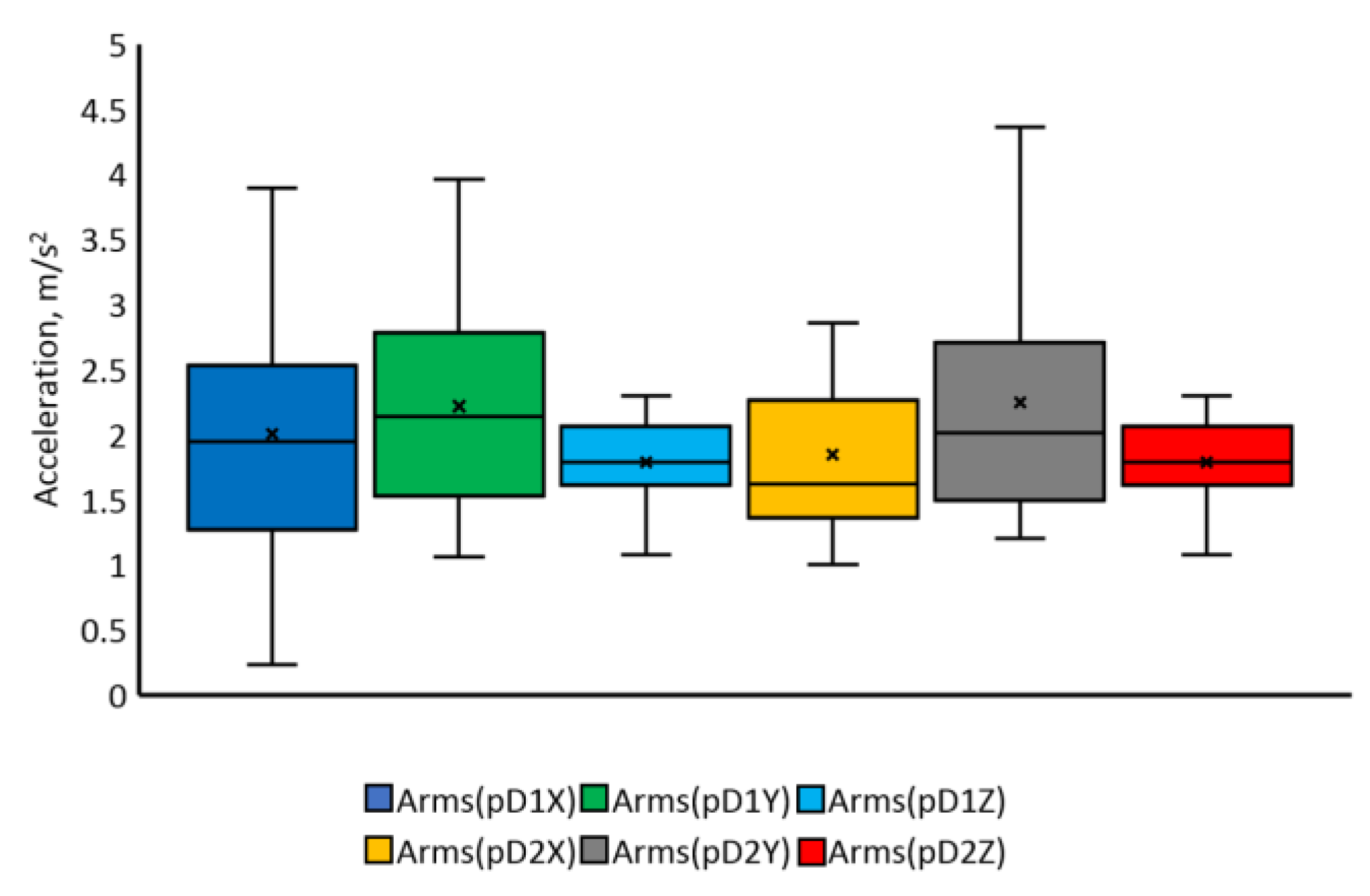
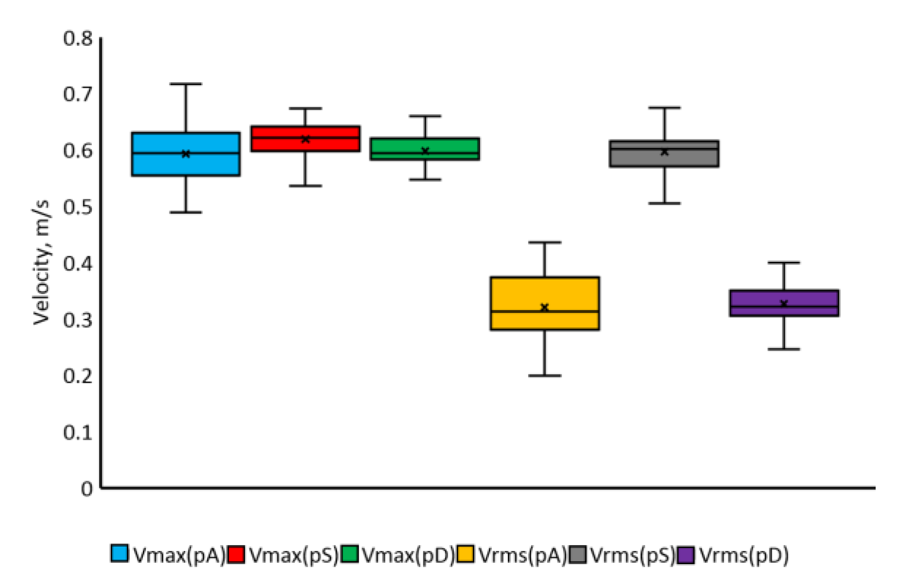
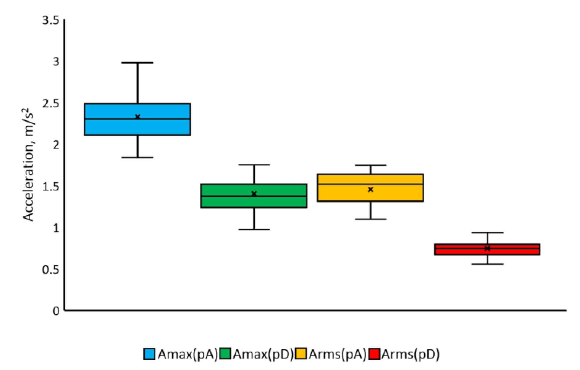
3.2. Results of Research on Rectilinear Precise Movements

An example of the course of displacement, velocity, and acceleration obtained from the study of precise hand movements for one of the operators is shown in Figure 17. As in the case of reaching movements, three phases of movement can be distinguished: pA—acceleration phase, pS—steady motion phase, and pD—deceleration phase. The duration of the deceleration phase is about 25% longer than that of the acceleration phase. The summary of the values of maximal speeds and maximal accelerations as well as RMS speeds and RMS accelerations obtained during the tests of precise hand movements are presented in Figure 18 and Figure 19.
Analyzing the graphs (Figure 17, Figure 18 and Figure 19), it can be seen that the median value of maximal accelerations in the acceleration phase (2.3 m/s2) is less than half the median of maximal acceleration values in the acceleration phase obtained in the study of reaching movements. In contrast, the median value of the maximal acceleration in the deceleration phase (1.3 m/s2) is close to 3-fold lower than the median value of the maximal acceleration in the deceleration phase of reaching movements. The median value of maximal speed in the acceleration phase (0.58 m/s) is half the median value of maximal speed obtained in the acceleration phase of reaching movements. The maximal speeds in the acceleration phase for the three quartiles reach 0.65 m/s, and the accelerations 2.5 m/s2. Thus, they are 12% and 9% higher, respectively, than the median value.
Based on the results of the study of precise movements, the average values of maximal speeds and maximal accelerations, as well as average values of RMS speed and RMS accelerations for each movement phase (pA, pS, and pD), were determined. The calculated parameters are summarized in Table 2.
The average maximal speed value for all movement phases is similar and is about 0.6 m/s—approx. 40% lower than the average maximal speed of reaching movements. The average RMS speed in the acceleration and deceleration phase is approx. 45% lower than the maximal speed values in these phases of motion.
The average maximal acceleration in the acceleration phase is approx. 2.3 m/s2 and is about 50% of the value of the average maximal acceleration in the acceleration phase in the study of reaching movements. The coefficient of variation for maximal speed and effective RMS speed ranges from 4% to 15%. This indicates a high homogeneity in the studied population.
The compilation of the dropout errors in relation to the x and y axes obtained during the tests by all operators is shown in Figure 20. Analyzing the obtained test results (Figure 20), it can be noticed that the average error of putting the object off does not exceed 0.5 mm. The first quartile of the withdrawal error concerning the x axis is −1.8 mm, and the third quartile is 0.5 mm. The yaw-off error to the y-axis for the first quartile is 1.2 mm, and for the third is 1.3 mm. Therefore, no less than 50% of attempts to complete the task were carried out with the assumed accuracy.

4. Discussion

The obtained test results are characterized by a normal distribution close to the Gaussian curve (p > α). The power of the test (>80%) was sufficient to show the differences between the tested parameters of human upper limb movements. Most of the parameters determined in the studies of human hand movements are characterized by a low coefficient of variation (Cv < 25%). Therefore, they can be applied to most people, and give very important information about the dynamics of the human hand as an element controlling the movement of the anthropomorphic manipulator effectors and about the possibilities of controlling anthropomorphic manipulators by means of hand movements, controlling the position of the effector in a master–slave system.
The values of averaged maximal speeds and averaged maximal accelerations obtained as a result of the conducted tests indicate that there are significant differences between the reaching and precise movements of the human limb. The direction of the movement (longitudinal, lateral, and vertical) has no significant influence on the maximal speed achieved. The median value of the maximal speed of reaching movements is 1 m/s, while the maximal speed for the three quartiles is approximately 1.3 m/s.
The speed values obtained as a result of precise hand movement tests are nearly 50% lower than the speeds of reaching movements. A significant reduction in the speed value, in relation to the reaching movements, indicates that a task that requires strictly defined precision forces the operator to work at lower speeds, which significantly extends the time needed to complete the task. The results are consistent with the test results presented in [103]; however, the presented research covers a much larger range of motion and various directions.
The conducted research showed that there are no significant differences between the velocity of motion to achieve the target and return movement—longitudinal movement—Figure 7, lateral movement—Figure 6, and vertical movement—Figure 5.
The median value of maximal acceleration during reaching movements (all phases) was 4 m/s2 and was about 50% higher than in the case of precise movements. It should be noted that the acceleration values are not fixed in the acceleration and deceleration phases. The maximal acceleration values usually occur in the initial phase and decrease quickly, although there are incidental hard deceleration cases. It is confirmed by a large difference between the values of averaged maximal accelerations and the effective values of RMS accelerations. Direct copying of such movements can result in significant dynamic loads on the manipulator. In the case of mechanical hand tracking systems, it is possible to reduce acceleration by increasing the resistance to hand movement by introducing friction or using servos with haptic feedback. In the case of optical tracking systems, it may be necessary to optimize the control signals in the master–slave control system.

5. Conclusions

Thanks to the use of an innovative method of measuring hand movements with the use of a system of stereovision cameras, high accuracy of hand displacement measurements was achieved. These allowed us to determine the maximum values of velocity and acceleration of longitudinal, lateral, and vertical movements of the human hand. Research has shown that regardless of the direction of movement (longitudinal, lateral, vertical), the maximum velocity values are close and amount to approximately 1 m/s. Moreover, they showed that during a movement longer than 0.4 m, there is a steady phase in which the speed of movement is constant.
The conducted research has shown that there are no relations between the direction of hand movement (longitudinal, lateral transverse, vertical) and the obtained speed of movement. The test results also show a significant difference in the achieved speeds of reaching and precise movements. Therefore, the null hypotheses made should be rejected.
The obtained research results allow for a better design of manipulator control systems operating in the master–slave system. The measured speed values can be used as inputs in the master–slave manipulator control system. Moreover, they allowed us to determine the accelerations that can be generated by the operator during steering with hand movements.
To control a manipulator with a much larger working area in relation to human reach, with speeds multiplied in relation to the speeds obtained from the tests. It is likely that operating at such high speeds may not be possible due to limited operator perception. Therefore, it is necessary to conduct further research on the possibilities of controlling manipulators with extended range, which depend mainly on the perception of the operator and the mobility of the limbs.

Author Contributions

Conceptualization, K.C. and M.J.Ł.; methodology, M.J.Ł.; software, K.C.; validation, K.C. and M.J.Ł.; formal analysis, M.J.Ł.; investigation, K.C.; resources, K.C.; data curation, K.C.; writing—original draft preparation, K.C.; writing—review and editing, M.J.Ł.; visualization, K.C.; supervision, M.J.Ł.; project administration, M.J.Ł.; funding acquisition, M.J.Ł. All authors have read and agreed to the published version of the manuscript.

Funding

This research was funded by Military University of Technology under project number UGB 22-757/2022 (“Rozwój technik wytwarzania konstrukcji mechanicznych i systemów sterowania maszynami”).

Institutional Review Board Statement

All subjects gave their informed consent for inclusion before they participated in the study. The study was conducted in accordance with the Declaration of Helsinki, and the protocol was approved by the Ethics Committee operating at Warsaw University of Life Science, resolution number 6/2022.

Informed Consent Statement

Not applicable.

Data Availability Statement

Not applicable.

Conflicts of Interest

The authors declare no conflict of interest.

References

  1. Su, C.; Zhang, S.; Lou, S.; Wang, R.; Cao, G.; Yang, L.; Wang, Q. Trajectory coordination for a cooperative multi-manipulator system and dynamic simulation error analysis. Robot. Auton. Syst. 2020, 131, 103588. [Google Scholar] [CrossRef]
  2. Nie, S.-C.; Qian, L.-F.; Chen, L.-M.; Tian, L.-F.; Zou, Q. Barrier Lyapunov functions-based dynamic surface control with tracking error constraints for ammunition manipulator electro-hydraulic system. Def. Technol. 2020, 17, 836–845. [Google Scholar] [CrossRef]
  3. Wang, T.; Chen, X.; Qin, W. A novel adaptive control for reaching movements of an anthropomorphic arm driven by pneumatic artificial muscles. Appl. Soft Comput. 2019, 83, 105623. [Google Scholar] [CrossRef]
  4. Barbieri, L.; Bruno, F.; Gallo, A.; Muzzupappa, M.; Russo, M.L. Design, prototyping and testing of a modular small-sized underwater robotic arm controlled through a Master-Slave approach. Ocean. Eng. 2018, 158, 253–262. [Google Scholar] [CrossRef]
  5. Chen, G.; Yuan, B.; Jia, Q.; Sun, H.; Guo, W. Failure tolerance strategy of space manipulator for large load carrying tasks. Acta Astronaut. 2018, 148, 186–204. [Google Scholar] [CrossRef]
  6. Morecki, A.; Knapczyk, J.; Kędzior, K. Teoria Mechanizmów i Manipulatorów; WNT: Warszawa, Poland, 2002. [Google Scholar]
  7. Morecki, A.; Knapczyk, J. Podstawy Robotyki Teoria i Elementy Manipulatorów i Robotów; WNT: Warszawa, Poland, 1999. [Google Scholar]
  8. Zanchettin, A.M.; Bascetta, L.; Rocco, P. Achieving humanlike motion: Resolving redundancy for anthropomorphic industrial manipulators. IEEE Robot. Amp. Amp Autom. Mag. 2013, 20, 131–138. [Google Scholar] [CrossRef]
  9. Artemiadis, P. Closed-Form Inverse Kinematic Solution for Anthropomorphic Motion in Redundant Robot Arms. Adv. Robot. Autom. 2013, 2, 110. [Google Scholar] [CrossRef] [Green Version]
  10. Sandoval, J.; Su, H.; Vieyres, P.; Poisson, G.; Ferrigno, G.; De Momi, E. Collaborative framework for robot-assisted minimally invasive surgery using a 7-DoF anthropomorphic robot. Robot. Auton. Syst. 2018, 106, 95–106. [Google Scholar] [CrossRef] [Green Version]
  11. Jin, L.; Li, S.; La, H.M.; Luo, X. Manipulability Optimization of Redundant Manipulators Using Dynamic Neural Networks. IEEE Trans. Ind. Electron. 2017, 64, 4710–4720. [Google Scholar] [CrossRef]
  12. Guo, D.; Feng, Q.; Cai, J. Acceleration-Level Obstacle Avoidance of Redundant Manipulators. IEEE Access 2019, 7, 183040–183048. [Google Scholar] [CrossRef]
  13. Xie, Z.; Jin, L.; Luo, X.; Li, S.; Xiao, X. A Data-Driven Cyclic-Motion Generation Scheme for Kinematic Control of Redundant Manipulators. IEEE Trans. Control Syst. Technol. 2021, 29, 53–63. [Google Scholar] [CrossRef]
  14. Chu, Z.; Ma, Y.; Hou, Y.; Wang, F. Inertial parameter identification using contact force information for an unknown object captured by a space manipulator. Acta Astronaut. 2017, 131, 69–82. [Google Scholar] [CrossRef]
  15. Xu, W.; Peng, J.; Liang, B.; Mu, Z. Hybrid modeling and analysis method for dynamic coupling of space robots. IEEE Trans. Aerosp. Electron. Syst. 2016, 52, 85–98. [Google Scholar] [CrossRef]
  16. Ni, F. Research on Joint Drive and Control of Space Robot Arm. Ph.D. Thesis, Harbin Institute of Technology, Harbin, China, 2006. [Google Scholar]
  17. He, J.; Zheng, H.; Gao, F.; Zhang, H. Dynamics and control of a 7-DOF hybrid manipulator for capturing a non-cooperative target in space. Mech. Mach. Theory 2019, 140, 83–103. [Google Scholar] [CrossRef]
  18. Sivčev, S.; Coleman, J.; Omerdić, E.; Dooly, G.; Toal, D. Underwater manipulators: A review. Ocean. Eng. 2018, 163, 431–450. [Google Scholar] [CrossRef]
  19. Boubaker, O. Chapter 7—Medical robotics. In Control Theory in Biomedical Engineering; University of Carthage, National Institute of Applied, Sciences and Technology: Tunis, Tunisia, 2020; pp. 153–204. [Google Scholar]
  20. Bogue, R. Robots in healthcare. Ind. Robot 2011, 38, 218–223. [Google Scholar] [CrossRef]
  21. Bucolo, M.; Buscarino, A.; Fortuna, L.; Gagliano, S. Force Feedback Assistance in Remote Ultrasound Scan Procedures. Energies 2020, 13, 3376. [Google Scholar] [CrossRef]
  22. Perry, J.C.; Rosen, J.; Burns, S. Upper-limb powered exoskeleton design. IEEE/ASME Trans. Mechatron. 2007, 12, 408–417. [Google Scholar] [CrossRef]
  23. Nef, T.; Klamroth, V.; Duschau-Wicke, A.; Keller, U.; Guidali, M.; Riener, R. Transferring ARMin to the clinics and industry. Top. Spinal Cord Inj. Rehabil. 2011, 17, 54–59. [Google Scholar]
  24. Gopura, R.A.R.C.; Kiguchi, K.; Yang, L. SUEFUL-7: A 7DOF upper-limb exoskeleton robot with muscle-model-oriented EMG-based control. In Proceedings of the 2009 IEEE/RSJ International Conference on Intelligent Robots and Systems, IROS, St. Louis, MO, USA, 10–15 October 2009; pp. 1126–1131. [Google Scholar]
  25. Rahman, M.H.; Saad, M.; Kenne, J.P.; Archambault, P.S. Modeling and control of a 7DOF exoskeleton robot for arm movements. In Proceedings of the 2009 IEEE International Conference on Robotics and Biomimetics (ROBIO), Guilin, China, 19–23 December 2009; pp. 245–250. [Google Scholar]
  26. Caldwell, D.G.; Tsagarakis, N.G.; Kousidou, S.; Costa, N.; Sarakoglou, I. “Soft” exoskeletons for upper and lower body rehabilitation—Design. Int. J. Hum. Robot. 2007, 4, 549–573. [Google Scholar] [CrossRef]
  27. Vitiello, N.; Lenzi, T.; Roccella, S.; De Rossi, S.M.M.; Cattin, E.; Giovacchini, F.; Vecchi, F.; Carrozza, M.C. NEUROExos: A powered elbow exoskeleton for physical rehabilitation. IEEE Trans. Robot. 2013, 29, 220–235. [Google Scholar] [CrossRef]
  28. Liu, K.; Xiong, C. A novel 10-DoF exoskeleton rehabilitation robot based on the postural synergies of upper extremity movements. In Intelligent Robotics and Applications; Springer: Berlin/Heidelberg, Germany, 2013; pp. 363–372. [Google Scholar]
  29. Otten, A.; Voort, C.; Stienen, A.; Aarts, R.; van Asseldonk, E.; van der Kooij, H. LIMPACT: A hydraulically powered self-aligning upper limb exoskeleton. IEEE/ASME Trans. Mechatron. 2015, 20, 2285–2298. [Google Scholar] [CrossRef]
  30. Gopura, R.A.R.C.; Bandara, D.S.V.; Kiguchi, K.; Mann, G.K.I. Developments in hardware systems of active upper-limb exoskeleton robots: A review. Robot. Auton. Syst. 2016, 75, 203–220. [Google Scholar] [CrossRef]
  31. Ye, W.; Li, Z.; Yang, C.; Chen, F.; Su, C.-Y. Motion detection enhanced control of an upper limb exoskeleton robot for rehabilitation training. Int. J. Hum. Robot. 2017, 14, 1650031. [Google Scholar] [CrossRef] [Green Version]
  32. Qiu, S.; Li, Z.; He, W.; Zhang, L.; Yang, C.; Su, C.-Y. Brain-machine interface and visual compressive sensing-based teleoperation control of an exoskeleton robot. IEEE Trans. Fuzzy Syst. 2017, 25, 58–69. [Google Scholar] [CrossRef] [Green Version]
  33. Qu, J.; Zhang, F.; Wang, Y.; Fu, Y. Human-like coordination motion learning for a redundant dual-arm robot. Robot. Comput.-Integr. Manuf. 2019, 57, 379–390. [Google Scholar] [CrossRef]
  34. Suárez, R.; Palomo-Avellaneda, L.; Martinez, J.; Clos, D.; García, N. Development of a Dexterous Dual-Arm Omnidirectional Mobile Manipulator. IFAC-Pap. OnLine 2018, 51, 126–131. [Google Scholar] [CrossRef]
  35. Baigzadehnoe, B.; Rahmani, Z.; Khosravi, A.; Rezaie, B. On position/force tracking control problem of cooperative robot manipulators using adaptive fuzzy backstepping approach. ISA Trans. 2017, 70, 432–446. [Google Scholar] [CrossRef]
  36. Jinhui, W.; Zhehao, J.; Andong, L.; Li, Y. Vision-based neural predictive tracking control for multi-manipulator systems with parametric uncertainty. ISA Trans. 2020, 110, 247–257. [Google Scholar]
  37. García, N.; Suárez, R.; Rosell, J. First-Order Synergies for Motion Planning of Anthropomorphic Dual-Arm Robots. IFAC-Pap. OnLine 2017, 50, 2247–2254. [Google Scholar] [CrossRef] [Green Version]
  38. Asfour, T.; Do, M.; Welke, K.; Bierbaum, A.; Azad, P.; Vahrenkamp, N.; Gärtner, S.; Ude, A.; Dillmann, R. From Sensorimotor Primitives to Manipulation and Imitation Strategies in Humanoid Robots. In Robotics Research; Springer Tracts in Advanced Robotics; Pradalier, C., Siegwart, R., Hirzinger, G., Eds.; Springer: Berlin/Heidelberg, Germany, 2011; Volume 70. [Google Scholar]
  39. Christ, R.D.; Wernli, R.L. The ROV Manual, 2nd ed.; Butterworth-Heinemann: Burlington, MA, USA, 2014. [Google Scholar]
  40. Zhang, Y.; Xie, L.; Zhang, Z.; Li, K.; Xiao, L. Real-time joystick control and experiments of redundant manipulators using cosine-based velocity mapping. In Proceedings of the 2011 IEEE International Conference on Automation and Logistics (ICAL), Chongqing, China, 15–16 August 2011; pp. 345–350. [Google Scholar]
  41. Kot, T.; Krys, V.; Mostýn, V.; Novák, P. Control system of a mobile robot manipulator. In Proceedings of the 2014 15th International Carpathian Control Conference (ICCC), Velke Karlovice, Czech Republic, 28–30 May 2014; pp. 258–263. [Google Scholar]
  42. Baraniecki, L.; Hartnett, G.; Elliott, L.; Pettitt, R.; Vice, J.; Riddle, K. An Intuitive Wearable Concept for Robotic Control. In Human Interface and the Management of Information: Information, Knowledge and Interaction Design; Yamamoto, S., Ed.; Springer: Berlin/Heidelberg, Germany, 2017. [Google Scholar]
  43. Zareinia, K. Haptic-Enabled Teleoperation of Hydraulic Manipulators: Theory and Application; Department of Mechanical and Manufacturing Engineering, The University of Manitoba: Winnipeg, MB, Canada, 2011. [Google Scholar]
  44. Hayn, H.; Schwarzmann, D. A Haptically Enhanced Operational Concept for a Hydraulic Excavator. Adv. Haptics 2010, 10, 199–220. [Google Scholar] [CrossRef] [Green Version]
  45. Frankel, J.G. Development of a Haptic Backhoe Testbed. Master’s Thesis, School of Mechanical Engineering, Georgia Institute of Technology, Atlanta, GA, USA, 2004. [Google Scholar]
  46. Kontz, M.E. Haptic Control of Hydraulic Machinery Using Proportional Valves. Ph.D. Thesis, Georgia Institute of Technology, Atlanta, GA, USA, 2007. [Google Scholar]
  47. Bai, S.; Li, X.; Angeles, J. A review of spherical motion generation using either spherical parallel manipulators or spherical motors. Mech. Mach. Theory 2019, 140, 377–388. [Google Scholar] [CrossRef]
  48. Bai, S.; Virk, G.S.; Sugar, T. Wearable Exoskeleton Systems: Design, Control and Applications; Institution of Engineering and Technology: London, UK, 2018. [Google Scholar]
  49. Rupal, B.S.; Rafique, S.; Singla, A.; Singla, E.; Isaksson, M.; Virk, G.S. Lower-limb exoskeletons: Research trends and regulatory guidelines in medical and non-medical applications. Int. J. Adv. Robot. Syst. 2017, 14, 1729881417743554. [Google Scholar] [CrossRef]
  50. Dollar, A.M.; Herr, H.M. Lower extremity exoskeletons and active orthoses: Challenges and state-of-the-art. IEEE Trans. Robot. 2008, 24, 144–158. [Google Scholar] [CrossRef]
  51. Prabhu, M.K.; Sivaraman, P.; Vishnukaarthi, M.; Shankara Narayanan, V.; Raveen, S.; Keerthana, G. Humanoid gesture control arm with manifold actuation using additive manufacturing. Mater. Today Proc. 2020, 37, 717–722. [Google Scholar] [CrossRef]
  52. Chen, X.; Wang, T.; Zhao, Y.; Qin, W.; Zhang, X. An adaptive fuzzy sliding mode control for angle tracking of human musculoskeletal arm model. Comput. Electr. Eng. 2018, 72, 214–223. [Google Scholar]
  53. Asfour, T.; Azad, P.; Gyarfas, F.; Dillmann, R. Imitation learning of dual-arm manipulation tasks in humanoid robots. Int. J. Hum. Robot. 2008, 5, 183–202. [Google Scholar] [CrossRef]
  54. Ambar, R.B.; Sagara, S. Development of a master controller for a 3-link dual-arm underwater robot. Artif. Life Robot. 2015, 20, 327–335. [Google Scholar] [CrossRef]
  55. Sakagami, N.; Shibata, M.; Hashizume, H.; Hagiwara, Y.; Ishimaru, K.; Ueda, T.; Saitou, T.; Fujita, K.; Kawamura, S.; Inoue, T.; et al. Development of a human-sized ROV with dual-arm. In Proceedings of the Oceans’10 IEEE Sydney, Sydney, NSW, Australia, 24–27 May 2010; pp. 1–6. [Google Scholar]
  56. Liu, K.; Xiong, C.-H.; He, L.; Chen, W.-B.; Huang, X.-L. Postural synergy based design of exoskeleton robot replicating human arm reaching movements. Robot. Auton. Syst. 2018, 99, 84–96. [Google Scholar] [CrossRef]
  57. Liu, G.; Geng, X.; Liu, L.; Wang, Y. Haptic based teleoperation with master-slave motion mapping and haptic rendering for space exploration. Chin. J. Aeronaut. 2019, 32, 723–736. [Google Scholar] [CrossRef]
  58. Tahmasebi, A.M.; Taati, B.; Mobasser, F.; Hashtrudi-Zaad, K. Dynamic parameter identification and analysis of a PHANToM haptic device. In Proceedings of the 2005 IEEE Conference on Control Applications, Toronto, ON, Canada, 28–31 August 2005. [Google Scholar]
  59. Jarillo-Silva, A.; Dominguez-Ramirez, O.A.; Parra-Vega, V.; Ordaz-Oliver, J.P. PHANToM OMNI haptic device: Kinematic and manipulability. In Proceedings of the 2009 Electronics, Robotics and Automotive Mechanics Conference (CERMA), Cuernavaca, Morelos, Mexico, 22–25 September 2009. [Google Scholar]
  60. Garrec, P.; Friconneau, J.P.; Louveaux, F. Virtuose 6D: A new force-control master arm using innovative ball-screw actuators. In Proceedings of the ISR 2004: 35th International Symposium on Robotics, Villepinte, France, 23–26 March 2004. [Google Scholar]
  61. Lee, C.D.; Lawrence, D.A.; Pao, L.Y. Isotropic force control for haptic interfaces. Control Eng. Pract. 2004, 12, 1423–1436. [Google Scholar] [CrossRef]
  62. Vu, M.H.; Na, U.J. A new 6-DOF haptic device for teleoperation of 6-DOF serial robots. IEEE Trans. Instrum. Meas. 2011, 60, 3510–3523. [Google Scholar] [CrossRef]
  63. Rank, M.; Shi, Z.; Muller, H.J.; Hirche, S. Predictive communication quality control in haptic teleoperation with time delay and packet loss. IEEE Trans. Hum.-Mach. Syst. 2016, 46, 581–592. [Google Scholar] [CrossRef] [Green Version]
  64. Chen, Z.; Huang, F.; Song, W.; Zhu, S. A novel wave-variable based time-delay compensated four-channel control design for multilateral teleoperation system. IEEE Access 2018, 6, 25506–25516. [Google Scholar] [CrossRef]
  65. Chan, L.; Naghdy, F.; Stirling, D. Application of adaptive controllers in teleoperation systems: A survey. IEEE Trans. Hum.-Mach. Syst. 2014, 44, 337–352. [Google Scholar]
  66. Hirche, S.; Buss, M. Human-oriented control for haptic teleoperation. Proc. IEEE. 2012, 100, 623–647. [Google Scholar] [CrossRef]
  67. Steinbach, E.; Hirche, S.; Ernst, M.; Brandi, F.; Chaudhari, R.; Kammerl, J.; Vittorias, I. Haptic communications. Proc. IEEE 2012, 100, 937–956. [Google Scholar] [CrossRef]
  68. Zhang, D.; Wei, W. A review on model reference adaptive control of robotic manipulators. Annu. Rev. Control 2017, 43, 188–198. [Google Scholar] [CrossRef]
  69. Naranjo, J.E.; Lozada, E.C.; Espín, H.I.; Beltran, C.; García, C.A.; García, M.V. Flexible Architecture for Transparency of a Bilateral Tele-Operation System implemented in Mobile Anthropomorphic Robots for the Oil and Gas Industry. IFAC-Pap. OnLine 2018, 51, 239–244. [Google Scholar] [CrossRef]
  70. Wang, W.; Chi, H.; Zhao, S.; Du, Z. A control method for hydraulic manipulators in automatic emulsion filling. Autom. Constr. 2018, 91, 92–99. [Google Scholar] [CrossRef]
  71. Sim, K.B.; Byun, K.S.; Harashima, F. Internet-based teleoperation of an intelligent robot with optimal two-layer fuzzy controller. IEEE Trans. Ind. Electron. 2006, 53, 1362–1372. [Google Scholar] [CrossRef]
  72. Yang, X.; Hua, C.-C.; Yan, J.; Guan, X.-P. A new master-slave torque design for teleoperation system by T–S fuzzy approach. IEEE Trans. Control Syst. Technol. 2015, 23, 1611–1619. [Google Scholar] [CrossRef]
  73. Lu, Z.; Huang, P.; Liu, Z. Predictive approach for sensorless bimanual teleoperation under random time delays with adaptive fuzzy control. IEEE Trans. Ind. Electron. 2018, 65, 2439–2448. [Google Scholar] [CrossRef]
  74. Hace, A.; Franc, M. FPGA implementation of sliding-mode-control algorithm for scaled bilateral teleoperation. IEEE Trans. Ind. Inform. 2013, 9, 1291–1300. [Google Scholar] [CrossRef]
  75. Zhong, Y.; Yang, F. Dynamic modeling and adaptive fuzzy sliding mode control for multi-link underwater manipulators. Ocean. Eng. 2019, 187, 106202. [Google Scholar]
  76. Koivumäki, J.; Zhu, W.-H.; Mattila, J. Energy-Humanoid gesture control arm with manifold control of hydraulic robots. Control Eng. Pract. 2019, 85, 176–193. [Google Scholar] [CrossRef]
  77. Dhyani, A.; Panda, M.K.; Jha, B. Design of an evolving Fuzzy-PID controller for optimal trajectory control of a 7-DOF redundant manipulator with prioritized sub-tasks. Expert Syst. Appl. 2020, 162, 113021. [Google Scholar] [CrossRef]
  78. Chen, Z.; Pan, Y.J.; Gu, J. Integrated adaptive robust control for multilateral teleoperation systems under arbitrary time delays. Int. J. Robust Nonlinear Control. 2016, 26, 2708–2728. [Google Scholar] [CrossRef]
  79. Kang, S.; Kim, J.; Lee, J. Intuitive Control Using a Mediated Interface Module. In Proceedings of the International Conference on Advances in Computer Enterntainment Technology (ACE ’09), Athens, Greece, 29–31 October 2009; pp. 435–436. [Google Scholar]
  80. Liu, W.; Chen, D.; Steil, J. Analytical Inverse Kinematics Solver for Anthropomorphic 7-DOF Redundant Manipulators with Human-Like Configuration Constraints; Springer: Berlin/Heidelberg, Germany, 2016. [Google Scholar]
  81. Jaspers, J.E.N.; Shehata, M.; Wijkhuizen, F.; Herder, J.L.; Grimbergen, C.A. Mechanical Manipulator for Intuitive Control of Endoscopic Instruments with Seven Degrees of Freedom. In Proceedings of the ASME 2004 International Design Engineering Technical Conferences and Computers and Information in Engineering Conference, 28th Biennial Mechanisms and Robotics Conference, Parts A and B, Salt Lake City, UT, USA, 28 September–2 October 2004; Volume 2, pp. 377–386. [Google Scholar]
  82. Petrenko, V.I.; Tebueva, F.B.; Sychkov, V.B.; Antonov, V.O.; Gurchinsky, M.M. Calculating rotation angles of the operator’s arms based on generalized coordinates of the master device with following anthropomorphic manipulator in real time. Int. J. Mech. Eng. Technol. 2018, 9, 447–461. [Google Scholar]
  83. Yu, H.; Han, R.P.S. Real Time Dynamics and Control of a Digital Human Arm for Reaching Motion Simulation. In Proceedings of the ICAT 2006, Hangzhou, China, 9 November–1 December 2006; Lecture Notes in Computer Science. Springer: Berlin/Heidelberg, Germany, 2006; Volume 4282. [Google Scholar]
  84. Flash, T.; Meirovitch, Y.; Barliya, A. Models of human movement: Trajectory planning and inverse kinematics studies. Robot. Auton. Syst. 2013, 61, 330–339. [Google Scholar] [CrossRef]
  85. Petrenko, V.I.; Tebueva, F.B.; Gurchinsky, M.M.; Antonov, V.O.; Shutova, J.A. Solution of the dynamics inverse problem with the copying control of an anthropomorphic manipulator based on the predictive estimate of the operator’s hand movement using the updated Brown method. IOP Conf. Ser. Mater. Sci. Eng. 2018, 450, 042013. [Google Scholar] [CrossRef]
  86. Inam, R. Feasibility assessment to realise vehicle teleoperation using cellular networks. In Proceedings of the 2016 IEEE 19th International Conference on Intelligent Transportation Systems (ITSC), Rio de Janeiro, Brazil, 1–4 November 2016. [Google Scholar] [CrossRef]
  87. Jin, Y. Feasibility Study of Vehicular Teleoperation over Cellular Network in Urban Scenario. Ph.D. Thesis, KTH Royal Institute of Technology, School of Electrical Engineering, Stockholm, Sweden, 2017. [Google Scholar]
  88. Neumeier, S.; Walelgne, E.A.; Bajpai, V.; Ott, J.; Facchi, C. Measuring the Feasibility of Teleoperated Driving in Mobile Networks. In Proceedings of the 2019 Network Traffic Measurement and Analysis Conference (TMA), Paris, France, 19–21 June 2019. [Google Scholar] [CrossRef] [Green Version]
  89. Soret, B.; Mayorga, I.L.; Roper, M.; Wubben, D.; Matthiesen, B.; Dekorsy, A.; Popovski, P. LEO Small-Satellite Constellations for 5G and Beyond-5G Communications. IEEE Access 2020, 8, 184955–184964. [Google Scholar]
  90. Handley, M. Low Latency Routing in Space. In Proceedings of the 17th ACM Workshop on Hot Topics in Networks, Redmond, WA, USA, 15–16 November 2018; pp. 85–91. [Google Scholar] [CrossRef]
  91. Giuliari, G.; Klenze, T.; Legner, M.; Basin, D.; Perrig, A.; Singla, A. Internet Backbones in Space. ACM SIGCOMM Comput. Commun. Rev. 2020, 50, 25–37. [Google Scholar] [CrossRef] [Green Version]
  92. Polish Standard PN-80/N-08001; Ergonomic Design Data: Hand Reach Limits: Dimensions; Polish Committee for Standardization: Warsaw, Poland, 1980; (In Polish: Dane Ergonomiczne do Projektowania: Granice Zasięgu Rąk. Wymiary).
  93. Polish Standard PN-90/N-08000; Ergonomic Design Data: Dimensions of the Human Body; Polish Committee for Standardization: Warsaw, Poland, 1975; (In Polish: Dane Ergonomiczne do Projektowania: Wymiary Ciała Ludzkiego).
  94. Kübler. Linear Measuring Technology, Draw-Wire Encoder A50 Performance-Line, Fritz Kübler GmbH, Subject to Errors and Changes. June 2021. Available online: https://www.kuebler.com/en/products/measurement/linear-measuring-systems/product-finder/product-details/A50 (accessed on 20 August 2021).
  95. NiNOX™. Camera Systems High-Speed, High-Definition, Portable, NORAXON, Published January 2019. Available online: https://www.noraxon.com/noraxon-download/ninox-brochure/ (accessed on 20 August 2021).
  96. Fortuna, Z.; Macukow, B.; Wąsowski, J. Metody Numeryczne; PWN: Warszawa, Poland, 2015. [Google Scholar]
  97. Parviz, M. Fundamentals of Engineering Numerical Analysis; Cambridge University Press: Cambridge, UK, 2010. [Google Scholar]
  98. Koronacki, J.; Mielniczuk, J. Statystyka dla Studentów Kierunków Technicznych i Przyrodniczych; WNT: Warszawa, Poland, 2006. [Google Scholar]
  99. Sobczyk, M. Statystyka; Wydawnictwo Naukowe/PWN: Warszawa, Poland, 2007. [Google Scholar]
  100. Heumann, C.; Schomaker, M.; Shalabh. Introduction to Statistics and Data Analysis; Springer: Berlin/Heidelberg, Germany, 2016. [Google Scholar]
  101. Razali, N.M.; Wah, Y.B. Power comparisons of Shapiro-Wilk, Kolmogorov-Smirnov, Lilliefors and Anderson-Darling tests. J. Stat. Modeling Anal. 2011, 2, 21–33. [Google Scholar]
  102. Cortina, J.M.; Nouri, H. Effect Size for ANOVA Designs; SAGE Publication: Thousand Oaks, CA, USA, 2000. [Google Scholar]
  103. Rand, M.K.; Squire, L.M.; Stelmach, G.E. Effect of speed manipulation on the control of aperture closure during reach-to-grasp movements. Exp. Brain Res. 2006, 174, 74–85. [Google Scholar] [CrossRef] [Green Version]
Figure 1. Idea of using master-slave system in intervention operation: 1—removed objects, 2—picked object, 3—manipulator; 4—cameras; 5—displays; 6—hand; 7—human arm.
Applsci 12 03863 g001
Figure 2. Studies of reaching hand movements: (a) longitudinal movement tests; (b) lateral movement tests; (c) vertical movement tests; (d) test stand: 1—linear encoder, 2—moved element (handle grabbed by the operator’s hand), 3—guides, 4—data acquisition device, 5—spring stop, 6—power supply, 7—measurement card, A—starting point, B—point determining the goal of the movement.
Applsci 12 03863 g002aApplsci 12 03863 g002b
Figure 3. Scheme of precise hand movement tests. (A) Initial position of the carried object; (B) final position of the carried object; (a) actual distance of reference markers in relation to the x axis; (b) actual distance of reference markers in relation to the y axis.
Applsci 12 03863 g003
Figure 4. Stand for examining precise hand movements: 1—transferred object, 2—initial area in which the transferred object is located, 3—position marker, 4—stereovision camera, 5—device for data acquisition and processing, 6—area in which the transferred object should be located.
Applsci 12 03863 g004
Figure 5. An example course of changes in displacement, velocity, and acceleration for the vertical hand movement (displacement: 930 mm), where p is the phase of the movement.
Applsci 12 03863 g005
Figure 6. An example of the course of changes in displacement, velocity, and acceleration for the lateral movement of the hand (displacement: 730 mm), where p is the phase of the movement.
Applsci 12 03863 g006
Figure 7. An example of the course of changes in displacement, velocity, and acceleration for the hand longitudinal movement (displacement: 430 mm), where p is the phase of the movement.
Applsci 12 03863 g007
Figure 8. Duration of the individual stages of the movement, obtained during the study of the reaching movements of the hand.
Applsci 12 03863 g008
Figure 9. Summary of the maximal velocity values obtained in the study of reaching movements in the acceleration phase.
Applsci 12 03863 g009
Figure 10. Summary of RMS velocity values obtained in the study of reaching movements in the acceleration phase.
Applsci 12 03863 g010
Figure 11. Summary of the maximal velocity values obtained in the study of reaching movements in the deceleration phase.
Applsci 12 03863 g011
Figure 12. Summary of RMS velocity values obtained in the study of reaching movements in the deceleration phase.
Applsci 12 03863 g012
Figure 13. Summary of the maximal acceleration values obtained in the study of reaching movements in the acceleration phase.
Applsci 12 03863 g013
Figure 14. Summary of rms acceleration values obtained in the study of reaching movements in the acceleration phase.
Applsci 12 03863 g014
Figure 15. Summary of the values of maximal accelerations obtained in the study of reaching movements in the deceleration phase.
Applsci 12 03863 g015
Figure 16. Summary of rms acceleration values obtained in the study of reaching movements in the deceleration phase.
Applsci 12 03863 g016
Figure 17. The course of displacement, velocity and acceleration obtained during tests of precise hand movement.
Applsci 12 03863 g017
Figure 18. Summary of the maximal velocity and RMS velocity values obtained during tests of precise hand movement.
Applsci 12 03863 g018
Figure 19. Summary of the values of maximum acceleration and RMS acceleration obtained during tests of precise hand movement.
Applsci 12 03863 g019
Figure 20. Errors of putting the object off in relation to the x and y axis of precision tests.
Applsci 12 03863 g020
Table 1. Values of the determined parameters for reaching movements.
Type of MovementParameterMean ValueStandard DeviationCoefficient of Variation
pApSpDpApSpDpApSpD
longitudinalMaximal speed, m/s1.011.020.980.140.140.16141315
RMS speed, m/s0.590.940.540.070.130.14111325
Maximal acceleration, m/s25.390.173.591.380.051.45253040
RMS acceleration, m/s22.960.101.920.550.030.78182440
lateralMaximal speed, m/s1.081.101.080.280.200.24251922
RMS speed, m/s0.650.960.650.150.220.14222321
Maximal acceleration, m/s24.360.153.911.160.061.39264035
RMS acceleration, m/s22.720.082.230.640.030.84233837
verticalMaximal speed, m/s1.011.011.050.220.170.19221618
RMS speed, m/s0.621.00.530.100.160.13171623
Maximal acceleration, m/s24.760.153.580.910.060.10193928
RMS acceleration, m/s22.320.081.710.550.030.37233121
Table 2. Values of the calculated parameters for precise motion.
Name of the ParameterAverage ValueStandard DeviationVariation Coefficient
pApSpDpApSpDpApSpD
Maximal velocity, m/s0.590.610.600.060.030.03944
RMS velocity, m/s0.330.600.330.050.030.0315611
Maximal acceleration, m/s22.330.071.400.310.020.23132016
RMS acceleration, m/s21.450.030.750.210.010.1151112
Publisher’s Note: MDPI stays neutral with regard to jurisdictional claims in published maps and institutional affiliations.

