1. Introduction
Development processes are essential in software engineering, determining project workflows and approaches. Although most development processes can be generally called agile development nowadays, an architect still needs to customize processes for different projects. For user-centric system development, interface design could drive processes to enhance user experience in all aspects. For security-first system development, threat models could drive processes to satisfy security requirements. Tools vary in development processes. Apparently, prototyping tools are more useful for UI engineers than security engineers to weave interactions during user-centric system development. On the contrary, penetration testing tools are powerful for security engineers to find system vulnerabilities in security-first system development and may not be necessary to UI engineers. However, no matter what types of systems there are, one of the most important goals of the customized development processes is to implement requirements correctly. Conventionally, software testing techniques play a pivotal role in validating implementation correctness. Nevertheless, they are likely incapable of proving correctness with trade-offs for cost reduction, especially in nondeterministic cases.
Formal methods have proven effective in ensuring correctness by specifying and verifying system properties in a mathematically rigorous manner. Formal specification techniques are used to rigorously describe system behaviors and guide implementations with mathematical notations from various theories such as automata theory, mathematical logic, and type theory. Based on these theories, formal verification techniques are used to prove specified properties with respect to specifications. Compared to software testing techniques, formal methods are usually expensive and require more professional expertise and computing power. Nevertheless, many tools have been developed to advocate the use of formal methods in practice, such as model-checking tools [
1,
2] and theorem-proving tools [
3,
4]. These tools can be used to verify systems at the implementation (code) level or verify models extracted from implementations. In the first case, implementation verification focuses on the details of the execution, such as runtime bugs (e.g., null pointer, division by 0, buffer overflow), functional correctness bugs (e.g., undefined behaviors, unexpected algorithm output), and concurrency bugs (e.g., deadlock, race condition). It is crucial to verify implementations and even worthwhile analyzing bytecodes. However, the implementation verification is a unilateral strategy and hard to unravel design flaws. In the second case, it is possible to locate design flaws in a system by verifying the specified properties of models. However, extracting a proper model from the complicated implementation is nontrivial. Extracted models might be too simple to have useful properties or too complicated to be verified [
5]. It is hard to judge whether a model extracted from an implementation coincides with its design. If there is a departure from the design, properties associated with that model can be untrustworthy and meaningless, which we call a conformity issue. Therefore, a methodology that elaborates the adoption of formal methods tools is imperative in development. Considering the importance of development processes that control the whole development lifespan, an intuitive method of using formal methods throughout development processes could be the key.
Formalism-driven development (FDD) is an iterative and incremental development process, which was originally proposed for developing provably correct decentralized systems [
6]. To date, decentralization has evolved into a new stage with the advent of the blockchain technology [
7]. The blockchain was first introduced as the underlying technology of a decentralized payment system named Bitcoin [
8]. Later, it was extended by the smart contract [
9] and generalized to a concept named distributed ledger technology (DLT) [
10]. Based on DLT, numerous decentralized systems have been developed to address security and privacy issues in a wide range of fields such as Internet of Things (IoT) [
11,
12], data persistence [
13,
14], and security infrastructure [
15,
16]. However, developing a trustworthy decentralized system is extremely challenging due to threats and vulnerabilities. At the application level, the DAO attack [
17] in 2016, one of the most infamous attacks, brought great damage to the cryptocurrency market and successfully transferred about USD 50M worth of Ether into the control of the attacker by exploiting the re-entrancy vulnerability. In 2017, the Parity wallet firstly suffered a breach causing about USD 40M stolen [
18] in June, which was followed by a “suicide” attack in November that caused about USD 150M loss [
19]. Furthermore, more kinds of smart contract vulnerabilities were reported in [
18] such as re-entrancy and overflow. At the infrastructure level, Geth, the most widely used implementation of Ethereum virtual machine (EVM), was recently found to have a vulnerability (
https://github.com/ethereum/go-ethereum/security/advisories/GHSA-9856-9gg9-qcmq (accessed on 15 March 2022)) that led to a minority chain split after the London hard fork.
In contexts such as the development of decentralized systems, especially blockchains, complete empirical testing is not practical due to the uncontrollable environment factors (e.g., gas exactimation in Ethereum) and expensive financial expenses (e.g., high transaction fee in current main public blockchains). The cost of sufficient simulation testing for correctness verification may be no different from a solution based on formal methods. FDD aims to tackle the issues hindering the development of trustworthy decentralized systems with reasonable cost from the perspective of a development process that we regard as the root cause. FDD introduces a life cycle dominated by different types of formal methods to produce rigorous designs, mathematically verifiable models, and provably correct implementations. Formal specification techniques are used for producing readable, visualizable, and rigorous designs of which the correctness can be verified syntactically and semantically. Based on designs, formal specification techniques are also used to generate models that guide verification and implementation. In FDD, the design and model basically have the same semantics except that designs are usually at a higher abstraction level than models. Hence, we use design, model, and design model indistinguishably in this paper. Properties are formulated and proved in propositional and temporal logics to describe system functionalities. Furthermore, FDD puts strict constraints on iterations and increments by refinement techniques. Incremented components are formally defined with formulas and can be expanded into fundamental elements for design, verification, and implementation. Instead of functionalities, a set of (weakly) verified properties defines an effective iteration. In this manner, FDD ensures conformity during the system evolution.
In this paper, motivated by generalizing and promoting the adoption of FDD in various types of development projects, we systematically present the foundations of FDD. Starting from the basic concepts in
Section 2, we give a taxonomy of FDD in
Section 3 that organizes and unifies theories, architectures, and methods to help researchers to improve the underlying theories and engineers to build FDD tools. Furthermore, we formulate criteria of FDD tools and introduce Seniz, the first FDD framework to illustrate FDD in practice in
Section 4. Some limitations and misconceptions are discussed in
Section 6. We conclude our work with future directions of FDD in
Section 7.
2. Preliminaries
In this section, we introduce core concepts and theories related to FDD.
2.1. Basic Structures
Firstly, let us recall the Kripke structure, which is one of the commonly used models for formal specification.
Definition 1 (Kripke structure). Let P be a set of atomic propositions. A Kripke structure is a quintuple
S is a set of states,
is a transition relation;
is a set of initial states;
P is a set of atomic propositions; and
is a labeling function.
Relation R is left-total, i.e., . An atomic proposition is an indecomposable proposition defined in propositional logic. The labeling function relates a set of atomic propositions to any state s.
Notably, a Kripke structure is an unlabeled transition system. Therefore, it is preferred in state-based approaches for formal specification. For action-based approaches that assume only the executed actions are observable from outside, a labeled transition system plays a pivotal role.
In this paper, we define a variant of labeled transition system as below.
Definition 2 (Labeled Transition System).
A labeled transition system over set Var of typed state variables is a tuplewhere is a set of states;
A is a set of actions;
is a transition relation;
is a set of initial states;
P is a set of atomic propositions; and
is a labeling function.
The state space S is determined by , which is the set of evaluations of state variables Var. State is called a terminal state if it does not have any outgoing transitions, i.e., . The notation is used as shorthand for . In this paper, we assume that S, A, and P are finite sets.
In fact, a labeled transition system can be transformed into a Kripke structure and vice versa [
20,
21]. In this manner, we can formalize a system from either a state-based view or an action-based view according to concrete contexts.
In the remainder of this paper, we abbreviate labeled transition system to transition system.
Conditional branching is commonly used in modeling systems. By using conditional branching, it is possible to put constraints on actions. An action can only be triggered while the current evaluation of variables satisfies some conditions. We denote a set of Boolean conditions (propositional formulae) over Var as . In the interest of modeling conditional branching, we introduce conditional transitions.
Definition 3 (Conditional Transition).
A transition system with conditional transitions over set of typed state variables is a tupleaccording to Definition 2 with differences thatFor convenience, we use the notation as shorthand for . If the guard is a tautology, we can omit it, i.e., .
The behavior in state depends on the current state variable evaluation . The value of state variable is accessible through . For transition , the execution of action a is only triggered when evaluation satisfies guard g, i.e., . The new evaluation can be represented by changed state variables, e.g., , meaning that state variable x has value v in , and all other state variables are unaffected. Given a transition system with conditional transitions, it is natural that it can be transformed into an equivalent transition system without conditional transitions.
Definition 4 (Semantics of Conditional Transitions). Let be a transition system with conditional transitions over set Var of typed state variables. The corresponding transition system without conditional transitions is the tuple where
→ is defined by the following rule: ;
; and
and remain the same.
Remark 1 (State Tautology). If , the current state s and current state variable evaluation are interchangeable. The tuple can be reduced to either s or .
In this manner, we can define concepts on top of the transition system with conditional transitions on account of clearance.
2.2. Parallelism
Parallel systems can also be modeled by transition systems. In this paper, we introduce two common types of parallelism [
22]: asynchronous concurrency (pure interleaving) and synchronous concurrency (variable sharing).
Asynchronous concurrency models a parallel system composed of a set of interleaving subsystems, of which the next global state is nondeterministic.
Definition 5 (Asynchronous Concurrency of Transition System).
Given two transition systems with conditional transitions over and over , the asynchronous concurrency of them is defined by:where Synchronous concurrency models a parallel system whose subsystems share a global clock, where all subsystems make either a transition or an idle step on each clock pulse.
Definition 6 (Synchronous Concurrency of Transition System).
Given two transition systems with conditional transitions over and over , the synchronous concurrency of them is defined by:where Remark 2 (Variable Evaluation Merging and Demerging). Given two variable evaluations with , merging operator ⊕ merges them into one variable evaluation such that
; and
.
Given two variable evaluations with , Demerging operator ⊖ demerges a variable evaluation from another. produces a variable evaluation such that
Remark 3 (State Rewriting). If where and , s can be rewritten as a merged variable evaluation . Here, ⨁ notation is used to indicate repeated ⊕.
2.3. Communication
To model distributed systems, a communication model is indispensable. In this paper, we model the communication by channels. A channel is a buffer based on a queue where messages are stored and held to be processed later.
Given channel c, we define a set of functions to access the properties of c. c has a finite capacity and a domain . The current number of messages in c is fetched by Len(c). We can manipulate contents of c by a set of operations. puts message m at the rear of the buffer, whereas pops an element from the front of the buffer.
We introduce two actions for sending and receiving messages based on the operations of c.
: send the message m along channel c, i.e., ;
: receive a message via channel c and variable x has value of the message, i.e., .
With two message-passing actions, we define the set of communication actions Com as: , where Chan is a set of channels with typical element c and Var is a set of variables as in Definition 2.
Definition 7 (Channel System).
A transition system with conditional transitions over is a tupleaccording to Definitions 2 and 3 with the only difference that .A channel system over with , consisting of transition systems over is defined as Remark 4 (State Structure of a Channel System). Let be a channel system over . The global states S of are tuples of the form , where
is the current state (variable evaluation) of subsystem , i.e., ;
is the current variable evaluation (state) of , i.e., ; and
is the current channel evaluation.
is a mapping from channel onto a sequence such that , e.g., with . If , c is a synchronous channel. Otherwise, c is an asynchronous channel.
Notably, a channel system can have a nested structure; i.e., a subsystem can also be a channel system or parallel system. If a channel system only contains one transition system with conditional transitions, it is merely a transition system with conditional transitions and channel extension. Therefore, a channel system is capable of describing the complex structures and behaviors of a distributed system.
Furthermore, given a channel system, there exists an equivalent transition system
Definition 8 (Transition System Semantics of a Channel System).
Let be a channel system over withThe transition system of channel system is the tuplewhere ;
where τ is a distinguished symbol to represent all communication actions;
;
s;
; and
→ is defined according to different cases below.
Case 1 (Interleaving).
Given action ,where Case 2 (Asynchronous Message Passing). Let be a channel.
Case 3 (Synchronous Message Passing).
Given channel ,where . The interpretation from a channel system to a transition system can be automated according to the transition system semantics of a channel system, which permits us to model a system on top of a channel system without considering the details of its underlying transition system. It is also flexible to use different models or their combinations according to concrete contexts.
2.4. Properties
One important reason to mathematically model a system is to facilitate specifying and studying its properties in a rigorous way. In our current work, we use temporal logic, a formalism par excellence for mathematically expressing properties about system behaviors. More concretely, we use propositional temporal logic, including linear-time and branching-time logic.
Let us recall syntaxes of linear temporal logic (LTL) and computation tree logic (CTL).
Definition 9 (Syntax of Linear Temporal Logic).
The syntax of LTL formulae over a countable set P of atomic propositions is defined as follows:where . ◯
and ⊔
are two basic temporal modalities denoting next and until, respectively. ⋄
and □,
denoting eventually and always, are derived from ⊔
as follows: Definition 10 (Computation Tree Logic).
The syntax of CTL state formulae over a countable set P of atomic propositions is defined as follows:where and φ denotes a path formula. φ is formed according to the syntax below.where and are state formulae. Notably, the expressiveness of LTL and CTL are mathematically incomparable. They need to be used according to concrete contexts. When specifying properties of a complex system, both are indispensable most of the time.
3. Formalism-Driven Development
Formalism-driven development (FDD) is an iterative and incremental development process promoting formal methods throughout the lifespan. It is devised to take advantage of formal methods to eliminate design ambiguity, prove model properties, verify and test implementation correctness, and ensure conformity among design, model, and implementation. The core idea is to elaborate transition system theory to bond all concepts from formal specification, verification, and testing.
In fact, the philosophy of iterative and incremental development process has been widely practiced in agile development [
23]. Nevertheless, both iteration and increment are not formally defined in agile processes. Generally, iteration means enhancing systems progressively, while increment means delivering the system by pieces. However, it is hard to give a well-defined explanation about what an iteration or increment produces and relations between two iterations and relations between an iteration and an increment. In FDD, iteration and increment are defined based on a formalism with theory support, including modeling, refinement, and verification [
24]. With these well-defined theories, iterations and increments can be rigorously managed and used to produce verifiable deliveries.
In FDD, an iteration formulates a design model, proves model properties, implements the model, verifies the model implementation, and integrates or delivers the milestone. An increment organizes subsystems together as a higher-level system. Concretely, an iteration contains four stages: abstraction, verification, implementation, and integration, which is shown in
Figure 1. The
Abstraction Stage produces system graphs as design models. In the
Verification Stage, system graphs are verified by formal verification. The
Implementation Stage only accepts verified models to generate skeleton programs and implement concrete functionalities. In the
Integration Stage, system graphs are integrated into higher-level systems or delivered. Naturally, an increment comes from the
Integration Stage and can also launch a set of new iterations.
3.1. Abstraction Stage
In the Abstraction Stage, the goal is to produce a rigorous design model (system graph) for a system. If it is the first iteration of a new system, a model is built from the ground up, which is called the Origin Stage. Otherwise, we call it the Refinement Stage where a model from the last iteration is refined.
3.1.1. Origin Stage
The Origin Stage creates a system graph as a design model. A system graph is built on top of a channel system defined in Definition 7. Although they have equivalent expressiveness, a system graph cuts down the details that describe individual states by using a naming function to describe a group of states. Individual states are inferred from concrete contexts. This keeps a system graph succinct to model complex systems such as decentralized systems.
Definition 11 (System Graph).
A system graph over is a tuplewhere is a set of state declarators with names in N;
is a naming function;
is a set of actions;
is the conditional transition relation;
is the initial state declarator;
is the initial guard;
is a set of terminal state declarators;
is a set of propositions; and
is a labeling function.
Notably, a system graph uses state declarators to describe state sets and infer individual states instead of identifying each state explicitly. A state declarator introduces a kind of state with a given name into a system by identifying interesting state variables that are essential to show features of this kind of state. The name of a state declarator is unique, i.e., The naming function relates a set of variable evaluations, i.e., states, to any state declarator such that
; and
.
The conditional transition relation is on top of state declarators. Only one initial state declarator exists in a system graph. A system graph is nonterminal if . Propositions are well-formed propositional formulae in propositional logic and constructed from atomic propositions by logical connectives. A set of propositions are related to any variable evaluation, i.e., state, by the labeling function .
By using the state declarator, it enables describing a system in a succinct form. We are only concerned about the most critical features of states identified by interesting state variables. The evaluation of other state variables is inferred from the preceding state.
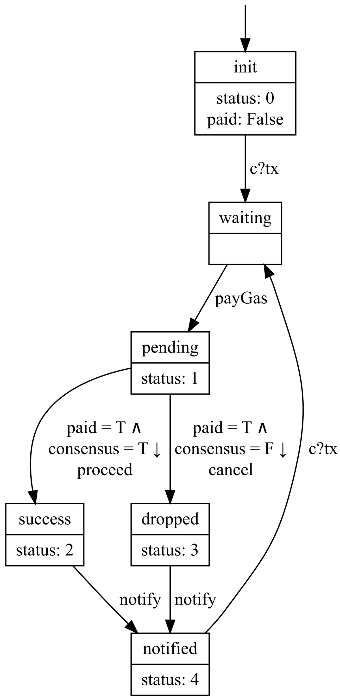
Example 1 (Transaction Client). We use a simplified transaction client in our developed demonstration as an example to illustrate core concepts in this paper. The complete demonstration fully developed by FDD is a prototype of Ethereum including the client-side and server-side systems.
A visualized system graph of the simplified transaction client is shown in Figure 2. Each box is a state declarator consisting of two parts. The big box is also an increment (illustrated in Section 3.4). The above part is a name, while the below part is a set of state variable evaluations. State variable status has type Integer and paid has type Boolean. A one-way arrow pointing from a state declarator to another is a transition relation with a guard and an action. The initial state declarator is pointed by an arrow without the starting node. We omit the representation of the guard if it is a tautology, e.g., the initial guard. Definition 12 (State Inference). Let be a system graph over . The state space S of is determined by .
Let be the current variable evaluation. According to Remark 3 and Definition 3, the succeeding state named by a state declarator is represented as a variable evaluation such that The initial state named by the initial state declarator i is represented as a variable evaluation such thatwhere ϵ denotes the default value. Example 2 (State Inference in Transaction Client). In Example 1, the state declarator named waiting does not identify any interesting state variables. According to Definition 12, the evaluation of state variables status and paid for the state declarator waiting remains the same with init; i.e., status has a value of 0 and paid has a value of False. However, waiting is distinguished from init by a hidden state variable tx. The state declarator waiting implies that the state variable tx has the value of the first element in channel c.
Remark 5 (Transition Interpretation).
In Definition 12, states of are inferred from contexts. Correspondingly, the declarator-based conditional transition relation ↪ of is interpreted to a state-based conditional transition relation by the following rule: Remark 6 (Transition System Semantics of a System Graph). Let S over be a system graph . According to Definitions 11 and 12, and Remark 5, can be transformed into a channel system with the requirement that
where denotes all atomic propositions contained in the conjunctive normal form of p.
By the transition system semantics of a channel system defined in Definition 8, can be interpreted over a transition system.
Notably, the termination of a system graph does not imply the termination of its underlying transition system and vice versa. F is omitted during the interpretation.
By interpreting a system graph over a transition system, we can use the high-level design model, system graph, to model systems while safely using transition system theory to support prominent features of FDD in later stages and iterations.
3.1.2. Refinement Stage
The
Refinement Stage accepts a system graph from the last iteration and produces a more detailed system graph while preserving and extending properties. According to Remark 6, a system graph can be interpreted onto a transition system. In FDD, we use both bisimulation and simulation theory [
25,
26] to support the refining process. The original purposes of these techniques are generally to optimize the verification process and improve verification efficiency by compacting a model while preserving its properties. However, the
Refinement Stage inverses the original purpose to extend a small model into a big one while preserving its properties.
A refined system graph (refinement) of is a more detailed design model that has either a strong relation ∼ or a weak relation ⪯ to . Relation ∼ is an equivalence relation that identifies and its refinement with the same branching structure by bisimulation. Relation ⪯ is a preorder. holds if the refinement can be simulated by .
Definition 13 (Bisimulation). Let and be two system graphs. With regard to their transformed transition systems over and over , a bisimulation for is a binary relation such that
,
- -
;
- -
;
where .
If there exists a bisimulation R for , then .
Definition 14 (Simulation). Let and be two system graphs. With regard to their transformed transition systems over and over , a simulation for is a binary relation such that
;
- -
,
- -
.
If there exists a simulation R for , then .
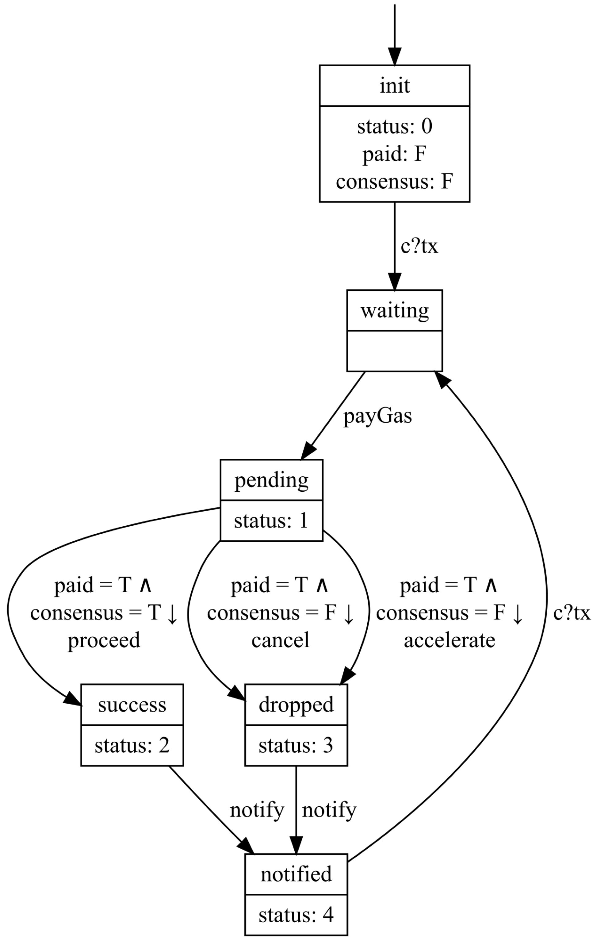
Example 3 (Refinement in Transaction Client). First, we assume that the system graph in Example 1 from the last iteration is the input of the current iteration. According to the gas mechanism of Ethereum, it may consume significant time for a network to reach consensus. Hence, it is helpful to provide accelerating service for the transaction client. Notably, the transaction client needs to cancel the original transaction firstly and resend a new transaction with more gas due to the immutability of the blockchain. Consequently, the current transaction is still dropped by the network.
We can get a refined system graph visualized in Figure 3. In fact, and are bisimulation-equivalent, which can be proved automatically by bisimulation.
Theorem 1 (Property Preservation). Let and be two system graphs. If , then
If , then
Example 4 (Property Preservation of Refined Transaction Client). According to Theorem 1, the refined system graph in Example 3 preserves all properties of in Example 1 specified in LTL and CTL.
For instance, the linear-time property of in Example 5 also holds for .
By using bisimulation and simulation techniques, the properties of an original system graph can be well preserved in the next iteration if the refined system graph passes either bisimilarity or similarity verification. While encountering a violation, it allows flexible handling methods. If the properties of the original system graph are finalized, then the refinement needs to be modified until passing the verification. It is also a solution to delegate the violation to the verification stage and resolve it by optimizing old properties.
3.2. Verification Stage
The Verification Stage produces a verifiable model based on the input system graph by specifying the admissible behaviors of the system graph as properties. In addition, it verifies properties associated with the verified model by formal verification.
3.2.1. Specification
According to Definition 11, a system graph has a set of propositions. Based on these propositions, we can specify essential system behaviors as a set of properties with temporal logic such as linear temporal logic and computation tree logic.
Example 5 (Linear-Time Property in Transaction Client). To verify whether the transaction client in Example 1 eventually gets notified whenever the gas fee is paid, we firstly define propositions and with respect to system graph .
Then, we can formally specify the property as . By the labeling function of , the states are automatically labeled with corresponding propositions. In this manner, the satisfiability of the property can be verified on the transition system under .
3.2.2. Enforcement
The enforcement of verification processes depends on the verification mode of FDD. Either a model checker or a theorem prover can be used to prove properties formulated in a formal logic.
Checker Mode
By structuring a system graph and interpreting it over a transition system, it is trivial to enforce model checking to verify the properties.
Prover Mode
The properties of a system graph are verified by a theorem prover that mechanizes the logic used to specify these properties.
3.3. Implementation Stage
In the Implementation Stage, a skeleton program is generated from the verifiable model. Based on the skeleton program, a real-world program is implemented with full functionality. In addition, a formal verification and testing process is enforced to ensure implementation correctness.
A skeleton program generated from the verifiable model has strict constraints to ensure conformity between the model and implementation at best efforts. The smallest skeleton program includes
- 1.
Predefined and immutable state variables;
- 2.
Predefined and immutable deterministic control flow; and
- 3.
Predefined and overridable action effects.
The term predefined means that the modificand is generated before the manual implementation. Something that can only be accessed but cannot be changed by implementors is immutable. An action effect of action a is the actual functionality produced every time executing a in the control flow. By overriding an action effect with an effect function, implementors can implement specific functionalities such as executing an algorithm, interacting with an I/O stream, etc.
Example 6 (Action Effect). In Example 1, all actions produce corresponding action effects such as , payGas, proceed, and notify. Each of them is overridable. For instance, a logging function can be called in each of them to write the current timestamp and action name into a local file system.
Depending on the programming paradigm, generated skeleton programs are different on the code level. In this paper, we illustrate possible generation methods with respect to two mainstream programming paradigms and key points.
3.3.1. General Skeleton
Object-Oriented Programming
The typical features of a system graph are extracted and formed as an abstract class that defines protected methods associated with the control flow and exposes an entry point to execute the system.
For a system graph over , it contains all the information to create an abstract class that is capable of fully describing . inherits and implements at least interface that contains a set of method signatures extracted from all manually labeled actions in A. also overrides the control flow according to . together with all its associated classes forms the smallest class set (skeleton program) to describe . The skeleton program is encapsulated into a package as a software development kit (SDK).
With such an SDK, implementors can create a concrete class that inherits . The implementors can override the effect methods (methods declared in ) to implement the functionality. Notably, implementors can neither modify state variables nor change the deterministic control flow. In this manner, the verified properties in Verification Stage are preserved in the executable system.
Functional Programming
In fact, it is straightforward to construct a system graph in functional programming. Related definitions can be easily formulated with customized data types. The impure action effects are isolated by the monad. All components are packaged into a module as a library that exposes a set of functions taking effect functions as their parameters and the entry point. The implementors can implement functionalities by passing the implementation of effect functions into the exposed functions.
3.3.2. Termination
A system graph is terminated if . The execution naturally terminates while reaching a terminal state declarator or a terminal state of its underlying transition system defined in Definition 2. Without considering exception handling, the execution generated from a nonterminal system graph interpreted over a nonterminal transition system will never naturally terminate such as the transaction client in Example 1.
3.3.3. Parallelism
In
Section 2.2, we present two types of parallelism: pure interleaving and variable sharing. Both present nondeterminism during the actual execution. The skeleton program handles them by multithreading techniques. Each system graph is encapsulated into a thread. In this manner, the implementation of nondeterminism in a parallel system is delegated to nondeterminism in thread scheduling.
3.3.4. Divergence and Confluence
A system graph may contain nondeterministic transitions after being interpreted over a transition system with conditional transitions. For a state s with a set of outgoing transitions, if there exist at least two transitions where , then it is a nondeterministic choice, which is called a divergence.
Example 7 (Divergence in Transaction Client). In our refined transaction client (Example 3), two transition relations from pending to dropped form a divergence because the truth values of their guards are the same.
To resolve a divergence, an interactive event is emitted to wait for a signal that determines a choice to resume the execution in that branch. An interactive event can be user input via I/O stream, in-memory or on-disk interaction with another program, communication through a network protocol, etc. The skeleton program exposes all divergences in the form of interfaces that need to be implemented as interactive events by implementors. While encountering a divergence, the execution pauses until getting a signal from the interactive event to proceed.
Example 8 (Divergence Resolution for Transaction Client). To resolve the divergence in Example 7, we can use a keyboard event as the interactive event by implementing a keyboard listener in a local environment for testing. For instance, the effect of action cancel is triggered while getting an input sequence c\r\n.
In our demonstration, the transaction client is developed as a mobile application. Action effects are triggered by touching corresponding buttons in the UI.
Confluence is usually not an interesting problem because the state inference in Definition 12 eliminates the nondeterminism of implicit state variables during the execution. One exception is for a set of systems to be confluent in a parallel system that contains nondeterminism in implementation. If a parallel system has terminal states, then we say this parallel system is naturally confluent. Each terminal state is a confluence where nondeterminism is eliminated. For a parallel system without terminal states, it allows implementors to customize the confluence where all threads join by manually identifying the evaluation of state variables in that confluence.
3.3.5. Channel
According to Remark 4, a channel can be either synchronous or asynchronous. A synchronous channel usually serves synchronization purposes instead of data transfer within a system modeled by a system graph. Its data structure at least contains the metadata. For an asynchronous channel, it contains at least the metadata, a buffer, and a set of operations associated with the buffer.
Regarding the implementation, a channel has two types: internal channel and external channel. An internal channel only receives messages within the system while an external channel can also receive messages from the outside of the system. An internal channel is naturally embedded into the control flow, while an external channel requires interaction with processes outside of the system. An outside process can be a program that sends messages to channels (by in-memory or on-disk interactions), a user who can input messages to channels (by I/O stream), a network protocol that passes messages to channels (by port), etc. A skeleton program integrates built-in modules to support the implementation of external channels according to concrete requirements.
Notably, execution needs to take care of waiting for a channel. An internal channel c gets into waiting if c is synchronous and the sending system is not in the state right before sending a message or c is asynchronous and . If c is an external channel, it gets into waiting if no outside process sends a message to c.
Example 9 (Channel in Transaction Client). The transaction client in Example 1 has an anonymous action attached to the transition relation between init and waiting. This communication action will not proceed, i.e., channel c gets into waiting until it consumes a message via channel c. From the perspective of implementation, the execution only resumes when state variable has the value received from channel c.
In our implementation, information about a new transaction is pushed into channel c when that transaction is submitted.
3.3.6. Correctness Verification
After the functionality implementation, a correctness verification process is optionally enforced on fully implemented codes through formal verification and testing techniques. This optional process focuses on general verification items such as type safety and memory safety. Therefore, language-specific verification tools are needed to ensure implementation correctness by leveraging verification cost, which is out of the scope of FDD.
3.4. Integration Stage
The Integration Stage serves the overall bottom–up approach that embeds or integrates the input system graph into a higher-level system graph, which is an incremental process. This stage also determines the next move to continue the iteration or produce a delivery.
3.4.1. Increment
An increment has two types: horizontal increment and vertical increment. A horizontal increment is to embed a system graph into another one. Formally, embedding is defined as follows.
Definition 15 (Embedding).
Let be two system graphs over . System graph of embedding into in the place of state declarator is the tuplewhere, , ;
;
;
, ;
;
.
is a set of transition relations such that
- 1.
; and
- 2.
.
is a set of transition relations such that
- 1.
; and
- 2.
.
Remark 7 (Module). In Definition 15, if shares state declarators, actions, propositions, naming, and labeling functions with , i.e., , then is a module of .
While embedding into , if is a module of , ⊎ relation is changed to ∪.
A vertical increment is an integration of a system graph into another one through parallelisms or communications, i.e., the current system graph is regarded as a subsystem that is parallel with or communicates with other subsystems in a higher-level system.
Example 10 (Increment in Transaction Client).
In fact, system graph of the transaction client in Example 1 is a considerably high-level model. Each component encapsulates either a horizontal increment or a vertical increment. So does an increment. For a simple but clear instance, pending integrates a system graph depicted in Figure 4 where the rounded dashed box denotes the terminal state declarator.Clearly, this increment is a module of . According to Remark 7, we can visualize modularized in Figure 5. 3.4.2. Next Move
As the final stage of an iteration, the Integration Stage determines the next move according to the current system graph . If does not include all details in the design, then it is called refinable. Otherwise, it is unrefinable. If is not integrated into any other system graph, then it is called independent. Otherwise, it is dependent.
If is independent and unrefinable, then terminate its iterative and incremental process and deliver its implementation.
If is dependent and unrefinable, then integrates into a higher-level system graph , and start an iterative process of .
If is refinable, always go to the next iteration of .
4. Formalism-Driven Development in Practice
FDD is designed to be useful and usable to serve practical purposes. Particularly, we intend to minimize the efforts for developers to master FDD and be able to put it in production lines. To achieve this, new tools are required to practicalize FDD. In this section, we discuss the criteria of FDD tools, followed by an introduction of Seniz, a full-fledged framework for FDD. Furthermore, we use case studies to show how a system is developed under FDD with Seniz.
4.1. Criteria
We enumerate a number of functional and quality criteria for FDD tools. Functional criteria define the core functionalities, while quality criteria show important requirements for practicalizing FDD.
4.1.1. Functional Criteria
Structure Representation
In FDD, system graphs are fundamental elements. A language is necessary to represent system graphs and structures derived from them. Although a language in natural form can be used, a formal language is preferred in FDD for automation.
System graphs are designed to be easily represented and mechanized in various programming paradigms. In object-oriented programming, a system graph can be regarded as an object with properties (e.g., state declarators, transition relations, and propositions) and private methods (e.g., naming function and labeling function) executed while being instantiated. In declarative programming paradigms, a system graph is easier to be represented. For instance, a system graph can be defined by data types in functional programming. Notably, domain-specific languages designed and implemented to represent system graphs are likely to be more effective than general programming paradigms.
Stage Mechanization
FDD has a collection of mechanisms in different stages. A tool needs to correctly implement full or partial mechanisms for at least a type of structure representation. For a tool that only implements partial mechanisms, compatibility issues must be addressed to keep consistency among mechanisms.
In the Abstraction Stage, basic mechanisms such as State Inference and Transition System Transformation are required to interpret semantics of system graphs. In addition, (bi)simulation mechanisms are indispensable for the refinement. Depending on the goal of tools, verification mechanisms in the Verification Stage have two types of effective implementations. A tool can either directly verify the properties of a system graph or translate it together with its properties to another dedicated tool for verification purposes. Code generation algorithms play a pivotal role in the Implementation Stage to transform system graphs to executable programs with action effects. Furthermore, implementations should contain specific mechanisms to handle technical points such as termination, parallelism, divergence, confluence, and channel. The same with Structure Representation criteria, increment mechanisms including both horizontal and vertical increment mechanisms in the Integration Stage are independent of languages and paradigms and easy to be implemented. Additionally, a version control mechanism is required to manage the workflow decided in Next Move.
Design Visualization
Human-centered design should be a crucial aspect of an FDD tool. A design in FDD tools must be readable, intuitive, and rigorous. As core components, structures and some mechanisms should be visualized to improve readability and understandability. We define two levels of visualization: syntax level and semantics level. At the syntax level, a diagram correctly depicts structures described by system graphs such as figures in running examples:
Figure 2,
Figure 3,
Figure 4 and
Figure 5. Semantic-level diagrams are usually more expressive than syntax-level diagrams. They carry out computations in mechanisms and render results. For example,
State Inference can be enforced synchronously with the syntax-level rendering process or asynchronously triggered in an interactive manner. Furthermore, complex functionalities can be implemented based on semantic-level diagrams such as optimizing and refactoring system graphs.
4.1.2. Quality Criteria
Simplicity
FDD tools should have concise rules and verbose syntax to use. Concise rules aim to keep the usage as simple as possible to make developers master basic operations with a minimum knowledge of formal methods. Consequently, tools should encapsulate underlying mathematics and promote intuitive operations similar to widely used methods such as UML state machine for design and object-oriented programming for implementation.
A certain verbosity level means that syntactic sugar should be introduced for frequently used syntactic constructs. For instance, to construct a complex system graph, redundant and repeated works should be conveniently omitted or simplified with verbose statements that are automatically rephrased in fundamental syntax. Typical techniques such as parameterization and higher-order function can be used for this purpose. Parameterization can generalize system graphs to manufacture argument-dependent system graphs. Higher-order functions such as fold can help assemble complex system graphs and propositional formulas.
Applicability
Compatibility and modularity are crucial for applicability. For a dedicated tool, its applicability is not only determined by how powerful it is but also by how well it collaborates with other tools to contribute to the success of an FDD process. System architects may prefer compatible enhancements of current systems by introducing a new tool. For a comprehensive tool that implements a set of functionalities, modularity is essential, meaning that a tool should separate its functionalities and support enabling a subset of them without impairment. In this manner, system architects can select appropriate tools and build tech stacks to satisfy requirements in a development context.
Interoperability
A system developed with FDD tools should be able to communicate and integrate with systems developed under other development processes. FDD is not a silver bullet for developing all types of systems. Therefore, subsystems within a complex system may be developed in different processes. For those systems developed with FDD tools, high-level APIs play an important role in communicating with external systems without exposing internal states.
Testability
Currently, verification cannot replace testing and vice versa. FDD does not refuse testing techniques. On the contrary, testing is indispensable in FDD. Functionalities implemented by FDD tools need to be testable, especially implementations produced in the Implementation Stage. These functionalities require testing techniques to assist code-level verification tools to detect runtime exceptions caused by programming errors such as poorly implemented algorithms and compiler defects. In addition, for unverifiable properties in the Verification Stage, testing techniques can be used to verify correctness under certain constraints partially.
4.2. Seniz
Seniz is an FDD framework that provides a collection of tools to support FDD processes. As shown in
Figure 6, Seniz consists of a modeling language, a verification generator, a skeleton generator, and a version controller.
4.2.1. The Seniz Language
The Seniz language is a modeling language designed to abstract system graphs from real-world systems. It allows developers to formulate static structures by state declarators, dynamic changes by actions and transition relations, as well as expected system behaviors by formal propositions and properties. We use two examples to show the main features of the Seniz language and list the core syntax and common operators in
Appendix A.
Example 11 (Transaction Client with Seniz). A Seniz program that codes the system graph in Example 1 is shown in Listing 1.
Example 12 (Block Writing Problem). We provide another example that programs the block writing problem widely used in EVM implementations to enable multithread block persistence. For instance, a set of workers separately run in multiple threads to process received transactions, while an EVM should expect that only one thread can write the block and associated states to the database. Hence, a mutual exclusion mechanism is necessary only to allow a worker that has acquired a mutex to proceed with the writing function.
We use a generalized mechanism based on a semaphore to model this problem. We define a system graph Worker over a local variable set Vars in Listing 2 and a global variable set Lock in Listing 3. We simply use the variable loc to represent the current execution fragment.
To model the interleaving of a set of workers, we program a control system BlockWriting that instantiates two worker systems. We also formulate three LTL properties with respect to the satisfaction of the mutual exclusion and two types of fairness.
Listing 1. Transaction client coded in the Seniz language.
![Applsci 12 03415 i001]()
Listing 2. Block writing worker.
![Applsci 12 03415 i002]()
Listing 3. Global (shared) variable set
Lock.
![Applsci 12 03415 i003]()
In the program of Example 11, we define a system graph named TransactionClient over a state variable set TXClientVar and a channel set TxClientChan. We declare a set of named state declarators from line 8 to 33. The initial state declarator {status: 0, paid: false} is anonymous, which contains two state declarations describing interesting state variables. In fact, it is a form of abductive reasoning supported in the Seniz language. According to Definition 11, each state declarator has a unique name. To distinguish anonymous state declarators, the Seniz compiler applies the hash function to the inferred state variable evaluations and uses hash values as corresponding names.
A set of transition rules are declared from line 3 to 6. The simplest form of a transition rule should contain a source state declarator, a symbol ->, and a destination declarator. In this form, guard is regarded as tautology, action is interpreted as epsilon action (i.e., no action effect is emitted), and there is no global variable change. Nevertheless, a transition rule carries an action to emit effects such as line 6 where the transition from notified state declarator to waiting state declarator emits effects caused by action NofityTx. The transition can also be guarded by a propositional formula such as line 4 where the transition from pending to success requires the condition to be satisfied. Guards can be defined by propositions such as line 5 where proposition paymentFailed is put into square brackets to become a part of the guard for transition from pending to dropped, which implements the proposition definition in Definition 11. Additionally, we provide syntactic sugar to simplify sequential transitions such as the codes in line 14 and 15 of Listing 1.
Propositions are declared with keyword prop and structured by Boolean expressions and propositional expressions. We define three propositions from line 35 to 45. Proposition paidGas and notified are used to declare the LTL property in Example 5 from line 47 to 49.
In the Seniz language, we have two modifiers for a system graph: main and control. A modifier main notes the entry point of a program. Hence, any program must contain exactly one main system. A control system is a high-level system that represents a composition of subsystems. It has exactly one control statement to describe the parallelism of a set of subsystems. Keyword async denotes the asynchronous concurrency defined in Definition 5, while sync denotes the synchronous concurrency defined in Definition 6. In the BlockWriting control system shown in Listing 4, two Worker systems are instantiated as two asynchronous systems and share the global variable set Lock.
Listing 4. Block writing control system.
![Applsci 12 03415 i004]()
Additionally, the Seniz language supports system arguments and multi-file compilation for genericity and modularity. A system argument is a global constant carrying information from a higher-level system. System arguments of the main system, also called environment arguments, are supplied to a program at the beginning of execution. By using keyword import, a Seniz program allows importing system graphs, state variable sets, channel sets, and records defined in local or remote files.
Furthermore, the Seniz language translates a system graph into a DOT program for visualization. The program given in Example 11 is visualized in
Figure 7.
We can find that
Figure 7 has slight differences from
Figure 2 in Example 1. The Seniz compiler merges anonymous state declarators into named state declarators with their supersets of state variable declarations. Therefore, the
init state declarator is merged into the
waiting state declarator in
Figure 7. In addition, the Seniz compiler processes the system graph with state inference. In Example 11, two different
notified states are inferred and distinguished, which creates two separate branches in
Figure 7.
4.2.2. Verification Generator
Seniz provides a verification generator that translates Seniz programs developed in the abstraction stage into Promela programs for the verification stage.
A state declarator is translated into a macro and an inline. A macro is defined as the conjunction of all state variables identified in the declarator and additional critical variables inferred by the compiler.
Example 13 (State Declarator Translation for Promela). For the acquiredLock state declarator in Example 12, it is translated to a macro and an inline shown in Listing 5.
Listing 5. Translated
acquiredLock state declarator in Promela.
![Applsci 12 03415 i005]()
The transition relations, used to construct the control flow, are translated into a proctype.
Example 14 (Transition Relation Translation for Promela). A proctype is generated according to the translation relations programmed in Example 12, which is shown in Listing 6.
Listing 6. Translated transition relations in Promela.
![Applsci 12 03415 i006]()
The translation of propositions and temporal properties is trivial on account of the similar syntax between the Seniz language and the Promela language.
The generated Promela program can be directly used for verification by model checkers such as the SPIN model checker [
1]. For the Promela program generated from Example 12, the checking report implies property
mutexHolds is satisfied while both fairness properties are violated.
4.2.3. Skeleton Generator
The current version of Seniz supports generating Java and TypeScript programs from Seniz programs. The core method is illustrated in
Section 3.3 and follows the OOP paradigm.
The generator integrates a powerful toolchain to support the generated SDK and allows customizing the tech stack. The FDD developers only need to focus on the implementation of action effects.
Example 15 (Implementation of Action Effects). For the block writing in Example 12, the generated Java SDK contains an abstract class ActionExecutor that implements an interface Action including a method writeBlock generated from the non-epsilon action set. To implement the effect of action writeBlock, we only need to extend the abstract class ActionExecutor, which is shown in Listing 7.
The effect is quite simple, which prints the current Worker system identifier and state variable loc to the output stream at the beginning and end. In this example, we should not observe the interleaving outputs of different workers thanks to the verified property mutexHolds.
Listing 7. Implementation of the effect of action
writeBlock in Java.
![Applsci 12 03415 i007]()
Two SystemExecutors are generated with respect to the Worker system and BlockWriting control system. The Worker SystemExecutor extends an abstract and generic class SystemExecutorThread implementing the Callable interface. Hence, WorkerSystemExecutor can run in thread and managed by the Java ExecutorService integrated in the BlockWritingSystemExecutor. The BlockWriting SystemExecutor also handles setting global variables and system arguments.
Example 16 (Execution). To execute the system, we merely need to instantiate BlockWriting SystemExecutor and invokes method run. A demonstration is shown in Listing 8.
Listing 8. Executing the
BlockWriting control system in Java.
![Applsci 12 03415 i008]()
4.2.4. Version Controller
Additionally, a rigorous version controller is mechanized in Seniz. Based on the rigorous definition of iterations and increments illustrated in
Section 3.4 and cryptographic hash function, the version controller automatically archives iterations and increments and labels them with verified properties. Furthermore, the version controller supports the branching workflow.
- 1.
Create or refine a system graph with the Seniz language.
- 2.
Generate a Promela program from .
- 3.
Specify and verify the properties of by a model checker.
- 4.
If all specified properties pass verification, then move to the next step. Otherwise, go back to step 1.
- 5.
Generate a Java or TypeScript skeleton program and encapsulate it into an SDK from the verified .
- 6.
Implement exposed interfaces of the skeleton program such as action effects and interactive events with the support of the SDK to satisfy functional requirements.
- 7.
If is independent and unrefinable, terminate the workflow. If is dependent and unrefinable, integrate into a higher-level system graph to obtain , start a new parallel iteration in branch with , and go into the next iteration with . Otherwise, go into the next iteration with .
4.2.5. Graphical User Interface
Seniz has a web-based user interface and scaffolds to provide a lightweight IDE (integrated development environment). It facilitates project management, coding, debugging, and version control. An example of the main interface is shown in
Figure 8.
4.3. Evaluation of Seniz
Seniz is the first FDD framework, which implements core tools for FDD processes and satisfies all functional criteria. The Seniz language satisfies syntactic completeness, meaning that for each structure in FDD, there exists a corresponding representation in the Seniz language that can be formulated. In addition, system graphs defined in the Seniz language can be visualized and exported as design documents. Based on the Seniz language, the verification generator and skeleton generator help implement mechanisms in different stages.
For quality criteria, Seniz uses high-level APIs to encapsulate the underpinning mathematics of FDD and implements the support for parameterization and higher-order functions for simplicity. The generated skeleton programs can be directly used in Java or TypeScript environments to interact with other systems, which implements a certain level of interoperability.
However, the tools in Seniz are centered around the Seniz language and not usable out of the framework. In addition, the Seniz language is not testable and cannot recognize functional and computational errors. Moreover, performance issues become significant in visualization, compilation, and generation for complex system graphs [
6].
6. Discussion
FDD is a type of development process. Architects and project managers need to concretize FDD processes based on the development context, such as requirement specification, developer skills, tech stack, project budget, and duration. As an iterative and incremental process, components should be built from small portions that are refined repeatedly through FDD four stages and eventually formed by continuous integration as illustrated in
Section 3.4.
FDD is compatible with testing techniques. Testing is still the fastest way to check correctness in each stage, though SMT solvers such as Z3 [
51] can be used in daemons to validate some propositional formulas in real time. Furthermore, formal testing techniques such as model-based testing [
52] can be naturally integrated into FDD processes.
FDD is not a verification process. Verification is a critical step in FDD to the success of developing trustworthy systems. Nevertheless, design and implementation are also significant in FDD. The former improves development efficiency and system maintainability, while the latter ensures that deliveries satisfy the needs. In a concretized FDDD process, architects need different types of formal methods tools, including specification, verification, and optional testing according to the criteria in
Section 4.1 and the development context.
FDD is not a silver bullet. We do not intend to replace the existing development processes and methodologies completely but to provide an alternative and reference to promote the application of formal methods. Its applicability is highly restricted by the limitations of formal methods such as performance and automation while facing state explosion problems and provability issues.
FDD is not suitable for studying algorithms. Although mechanizing functional models of computation such as rewriting systems and Lambda calculus in FDD formalisms could be theoretically interesting, it is not very attractive for developers in practice.


