Article

Design of a Novel Long-Reach Cable-Driven Hyper-Redundant Snake-like Manipulator for Inspection and Maintenance

by
Carlo Canali
1,*,
Alessandro Pistone
1,†,
Daniele Ludovico
1,†,
Paolo Guardiani
1,†,
Roberto Gagliardi
1,†,
Lorenzo De Mari Casareto Dal Verme
1,2,
Giuseppe Sofia
1 and
Darwin G. Caldwell
1
1
Istituto Italiano di Tecnologia, ADVR Advanced Robotics, 16163 Genoa, Italy
2
University of Genoa, 16126 Genoa, Italy
*
Author to whom correspondence should be addressed.
These authors contributed equally to this work.
Appl. Sci. 2022, 12(7), 3348; https://doi.org/10.3390/app12073348
Submission received: 15 February 2022 / Revised: 23 March 2022 / Accepted: 24 March 2022 / Published: 25 March 2022
(This article belongs to the Special Issue Smart Robots for Industrial Applications)

Abstract

:
Robotic inspection and maintenance are gaining importance due to the number of different scenarios in which robots can operate. The use of robotic systems to accomplish such tasks has deep implications in terms of safety for human workers and can significantly extend the life of infrastructures and industrial facilities. In this context, long-reach cable-driven hyper-redundant robots can be employed to inspect areas that are difficult to reach and hazardous environments such as tanks and vessels. This paper presents a novel long-reach cable-driven hyper-redundant robot called SLIM (Snake-Like manipulator for Inspection and Maintenance). SLIM consists of a robotic arm, a pan and tilt mechanism as end-effector, and an actuation box that can rotate and around which the arm can wrap. The robot has a total of 15 degrees of freedom and, therefore, for the task of positioning the tool centre point in a bi-dimensional Cartesian space with a specific attitude, it has 10 degrees of redundancy. The robot is designed to operate in harsh environments and high temperatures and can deploy itself up to about 4.8 m. This paper presents the requirements that drove the design of the robot, the main aspects of the mechanical and electronic systems, the control strategy, and the results of preliminary experimental tests performed with a physical prototype to evaluate the robot performances.

1. Introduction

Many activities can benefit from robotic inspection, especially when this leads to an increase in the safety of human operators. Robots can be deployed into environments too dangerous to access, such as nuclear power plants, nuclear waste sites, closed vessels and tanks, and pipelines. In this context, the use of robotic systems represents a game-changer approach. These robots are not a replacement for human operators, but they support workers in performing tasks in hazardous environments that are not accessible with traditional methods. These devices can be employed in different applications, such as monitoring industrial plants and infrastructures [1,2] or quality control [3,4], providing a reduction in the intervention time and increasing the safety of workers. Moreover, an accurate and well-defined inspection plan increases the safety and efficiency of working environments and extends the lifetime of infrastructures [5], obtaining overall economic advantages. Furthermore, old infrastructures were often not designed to be inspected or satisfy current health and safety requirements [6]. In this context, the ability of robots to carry on sensors and inspect areas that are difficult to reach can be a crucial asset.
This work presents the design of a new long-reach cable-driven hyper-redundant robot developed to be deployable in a wide number of industrial applications, especially to inspecting confined (air deprived) and harsh environments. The robot, called SLIM (Snake-Like manipulator for Inspection and Maintenance), is designed to access large volumes through small openings such as storage tanks, containment vessels and power generators. The ability to withstand high temperatures, operate in hazardous environments and gain access through small apertures is the key feature driving the design.
By definition, hyper-redundant robots have a number of degrees of freedom (DOFs) much greater than the number of variables necessary to complete a specific task. These robots are widely employed since they can perform grasping, manipulation, and articulated movements within narrow spaces crowded with obstacles [7]. Their design is often bio-inspired: some examples are elephant trunk [8,9], octopus [10], and snake [11] robots. Unlike traditional 6-DOFs anthropomorphic industrial robots, inspection and, in particular, hyper-redundant robots are still an emerging market with demand from industrial [12,13], surgical, and medical applications [14].
Implementing cable actuation in robotics can improve actuators safety, payload capability and structural compliance. For example, in the medical field, where accurate motion, dexterity and safe interactions are crucial, the cable-driven mechanism is adopted for minimally invasive surgery [15]. In industrial fields, cable-driven mechanisms appear in various applications ranging from a parallel robot for logistics [16,17] to hyper-redundant robots for the inspection of complex and constrained devices [4,18,19] or maintenance in harsh environments [20,21] that cannot be reached by humans. In bio-inspired robots, cable-driven mechanisms are often used to mimic limb tendons [22,23]. A drawback of cable-driven mechanisms is the need to route the cables all along the structure complicating the design [24] and introducing friction effects due to their interaction with bushing and pulleys. Delivering motion accuracy requires precise modelling of the cable-drive mechanism to fully consider friction phenomena [25,26,27]. Another critical aspect is the intrinsic compliance of the cable transmission. The elasticity decreases performances concerning trajectory tracking, stability margin and residual vibrations. Different algorithms to reduce the effects of elasticity were proposed [28,29].
The main novelty introduced in this work is the design of a long-reach cable-driven hyper-redundant manipulator actuated by a number of actuators equal to the number of DOFs. In contrast, most long-reach cable-driven hyper-redundant manipulators have a number of actuators greater than the number of DOFs. Indeed, the X125 snake-arm [12] has 24 DOFs actuated by 36 motors, Super Dragon [21] has 11 DOFs actuated by 21 motors, and TALISMAN [30] has 5 DOFs actuated by 9 motors.

2. Materials and Methods

In this Section, the design of the robot and the methodology to assess its performances are provided. First, the description of the mechanical design and the electronic architecture of the robot are presented. Then, the control strategy is discussed. Finally, the experimental setup and the system simulation are given.

2.1. Design Requirements

The design of the robot was driven by the following set of requirements related to the task of inspecting sites such as containment vessels, storage tanks, depositories and underground storage facilities:
  • inspecting extended environments;
  • operating in harsh environments with temperatures up to 100 C;
  • being capable of entering areas through apertures as small as 40 cm × 40 cm ;
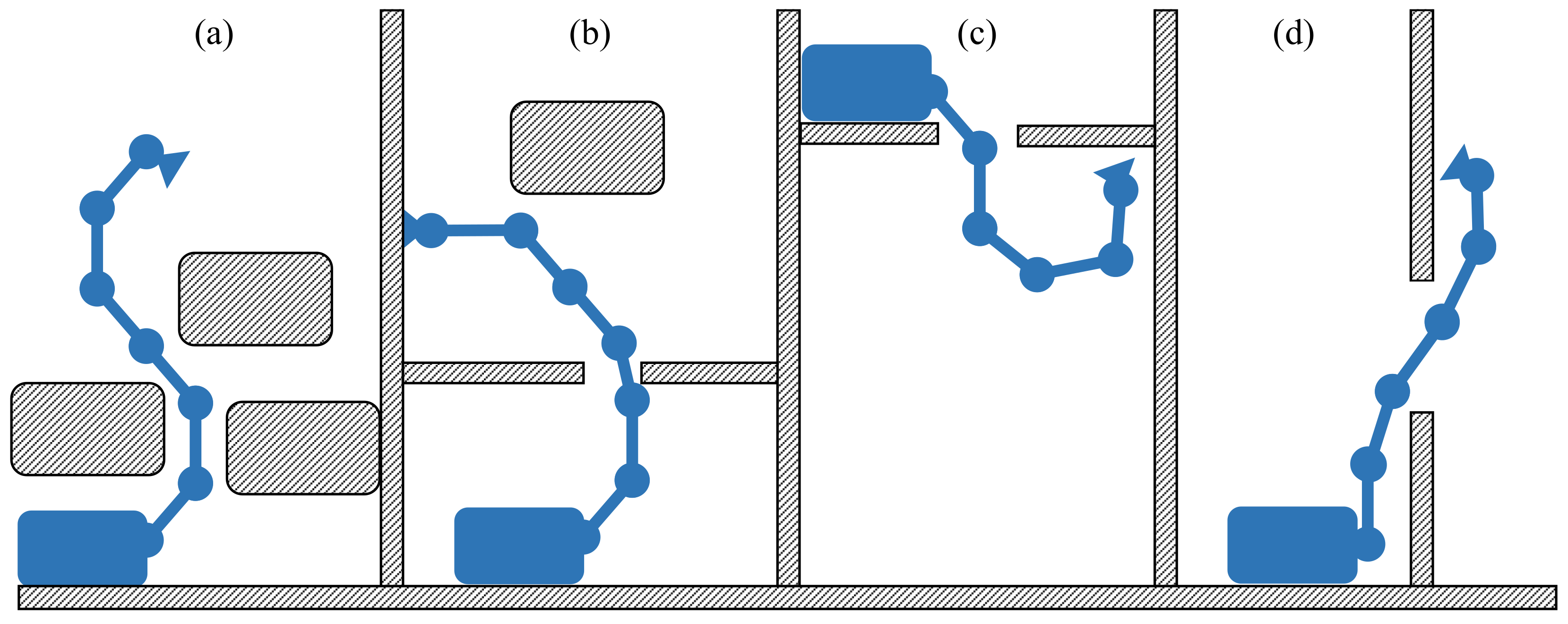
  • moving in narrow cluttered environments characterised by corners and obstacles;
  • carrying on-board instruments such as cameras, non-destructive testing devices, or other tools required to perform customised inspection tasks;
  • remaining compact (within a 160 cm × 100 cm × 160 cm L × W × H volume) in its parking configuration.
To satisfy these requirements, a long-reach cable-driven hyper-redundant robot was selected. In fact, a long-reach manipulator can inspect areas far from the robot base, hyper-redundancy allows a robot to avoid obstacles and move in narrow spaces, and cable actuation permits moving the actuators from joints to chassis, reducing the overall weight and size of the moving structure and increasing the payload capability even when the reach is extremely long. Furthermore, cable-driven mechanisms keep the actuators safe from possible extreme environmental conditions of the inspection site.
Figure 1 shows different possible scenarios that can benefit from the use of such a robot: in case (a) the robot needs to inspect an area moving around some obstacles; in case (b) it is necessary to pass through a small entrance to access an elevated area; in case (c) the robot needs to inspect an area that is under the ground level; in case (d) the entrance of the area to be inspected is on the side of a wall.

2.2. Design Overview

SLIM, shown in Figure 2, consists of four main components: a robotic arm, the actuation box, the robot base, and a dedicated device acting as the end-effector.
The robot can deliver the end-effector in a workspace up to 4.8   m from the base. The robotic arm is composed of 12 moving modules and is mounted on the actuation box. The actuators are located within the actuation box, which can rotate around the axis J 1 . The robot base supports the whole robot and is fixed to the ground. Then, a dedicated device acting as the end-effector is integral to the tip of the last module. Figure 3 shows the whole robotic system in its parking position.
Each module of the robotic arm is composed of a rigid link and a circular pulley acting as a revolute joint driven by a cable. The cables are routed along with the structure of the robot through rollers that constrain them to pass along the neutral axis of each link. The 12 parallel revolute joints allow moving the end-effector in a specific Cartesian position on a plane. The first joint is connected to the actuation box, which is able to rotate around an axis parallel to the axes of the other joints. The actuation box allows the arm to wrap on itself in a compact configuration and unroll as needed. In this application, the end-effector is a pan and tilt mechanism with 2 DOFs that allows a camera, acting as Tool Centre Point (TCP), to reach a desired attitude in the Cartesian space. Therefore, for the task of positioning the camera in a bi-dimensional Cartesian space with a specific attitude, SLIM has 10 degrees of redundancy. Assuming q i as the rotation angle of the ith joint, Table 1 lists the modified DH parameters, according to [31], describing the kinematics of the robot.

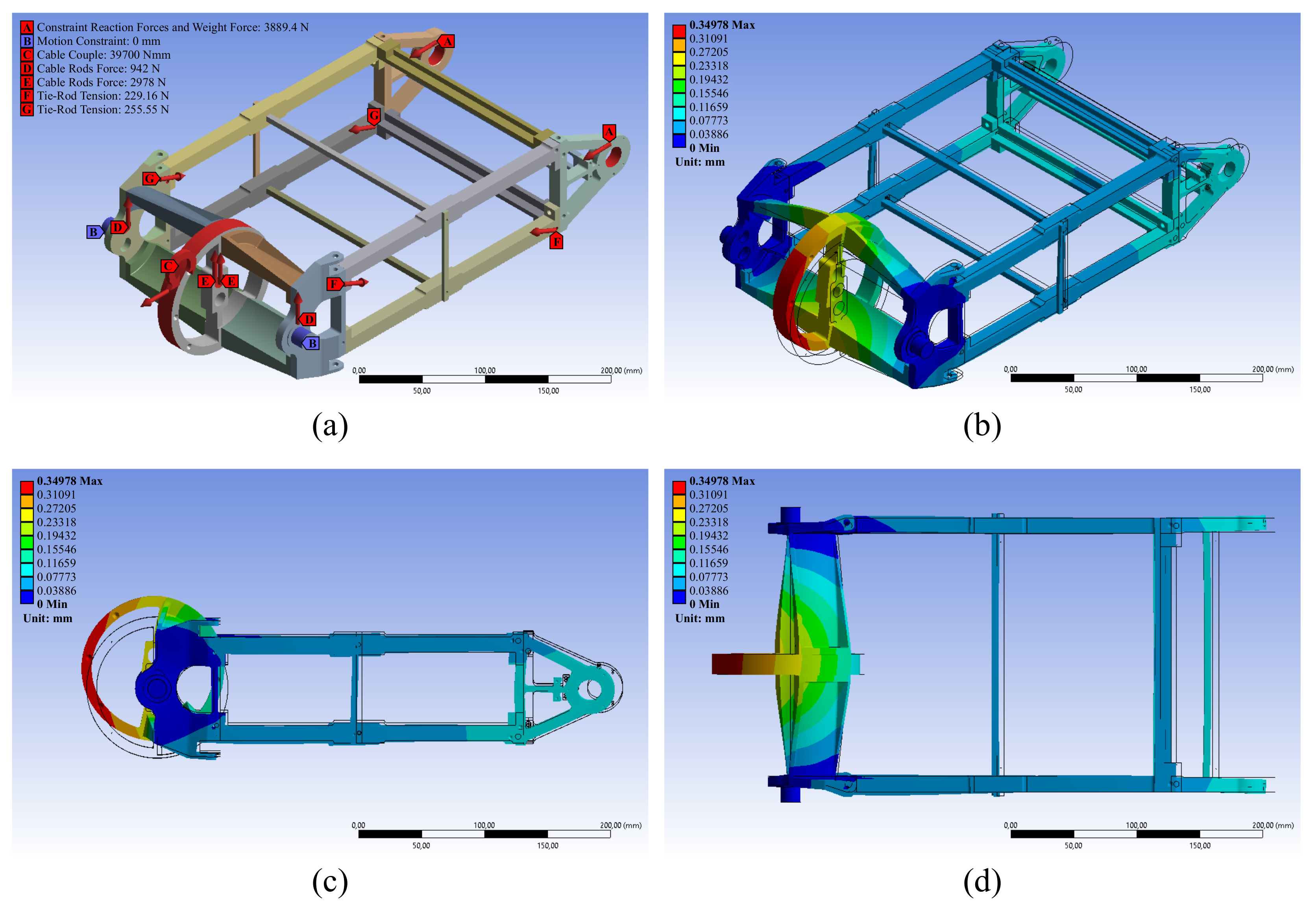
2.3. Mechanical Design

This Section provides a detailed mechanical description of SLIM.

2.3.1. Robotic Arm

The robotic arm is composed of 12 modules of six different sizes as shown in Figure 4. All the modules have the same length, but are in six different profiles to withstand the load due to the weight of the structure and the tension of the cables. In Table 2, for each module are reported the mass m, the x-coordinate of the centre of mass with respect to its frame defined by the DH parameters C o M x , the link length l, width w, and height h, and the pulley radius r. Each link is composed of four metal rods connecting two consecutive joints and of four pairs of cross tie-rods that increase the link stiffness. Each joint angular position, whose limits are π / 3 , π / 3 rad, is measured by an AkSim2 magnetic absolute encoder supplied by Renishaw. This sensor has a resolution of 18 bits with an accuracy of 0.0017 rad.
Each cable is fixed on both sides to a linear actuator and, passing through rollers made with IGLIDUR A350 assembled around two pairs of metal rods, transfers the power to the module through the friction between the pulley and the cable itself. The cables are made of a synthetic fiber called Zylon PBO [32]. This material was chosen because the more commonly used steel cables suffer from a few drawbacks mainly related to their weight per unit of length, their bending radius and difficulties in making simple and effective anchoring solutions. Table 3 compares the main characteristics of steel and Zylon PBO cables of equal diameter, 3mm, highlighting that Zylon PBO cables present higher payload and lower mass density with respect to steel. Keeping in mind the necessity to operate at high temperatures, it is also important to point out that Zylon PBO fiber can withstand temperatures up to 650 C. To ensure an efficient connection between the cable and the actuator, an eye splice is used to place a permanent loop in the end of a cable. This is an efficient method to connect a synthetic fiber rope to a fixed point without degrading the performances of the cable, retaining almost 100 % of the specified rope tensile strength [33]. The splicing of the cable is shown in Figure 5. The components chosen to build the robotic arm (Zylon PBO cables, communication and power wires, sensors, and modules materials) all tolerate temperatures up to 105 C.
The robotic arm structure was dimensioned starting from a static analysis considering the robot in the worst-case configuration, where all the modules are parallel to the ground, and a 1 kg payload applied on its tip. In this configuration, all the forces and constraint reaction forces acting on the arm were evaluated using FEM analysis to fully validate the design of the robot. The FEM analysis was performed on the 1st, 6th, and 12th module of the robotic arm and estimated a maximum total deformation of 0.350 mm, 0.257 mm, and 0.036 mm, respectively. Figure 6 reports the results on the 1st module, which is the one subject to the highest load: (a) shows the forces and constraint reaction forces acting on the module; (b), (c), and (d) show the corresponding total deformation from different points of view, with a deformation scale factor of 71. In Figure 6, A refers to the sum of the constraint reaction forces due to the successor modules and the weight force, B represents the axis on which the motion constraint is applied, C is the couple produced by the driving cable, D and E are the forces due to the rods that house the rollers, and F and G are the tensions of the most stressed tie-rods.

2.3.2. Actuation Box and Robot Base

The robot base consists of a metallic structure made of Bosch Rexroth 40   mm × 40   mm profiles and two custom designed Ergal plates. The base supports the actuation box, which carries 12 linear actuators. Each linear actuator drives one module and is composed of a two poles brushed DC motor (SVTN B 01-3571) and a three stages planetary gearbox (SVTG B 36), both provided by Servotecnica. Figure 7 shows the CAD model of a linear actuator. Each motor is controlled by an EPOS4 50/8 motor driver produced by Maxon.
The linear motion is obtained through a lead screw drive mechanism and is indirectly measured using an incremental encoder (HEDL-5540-A11), provided by Avago technologies, whose resolution is 500 pulses per turn. The gear ratio upstream of the screw is 211.5 and the pitch of the screw is 3 mm per turn. Figure 8 shows how the actuators transfer the motion to the joints via cables.
The actuation box motion, whose limits are 0 , 4 π rad, is driven by an eight poles brushless motor (EC45) and a planetary gearbox (GP42C), both produced by Maxon. An additional gearbox (SR MR V 50 UO3A), provided by the Rossi–Habasit Group, is mounted. The rotational motion is measured through an incremental encoder (HEDL 9140), provided by Avago technologies, whose resolution is 500 pulses per turn, and by an AkSim2 magnetic absolute encoder supplied by Renishaw, whose resolution is 18 bits with an accuracy of 0.0017 rad. The use of cable actuation moves the actuators, their drivers, the control system, and the power suppliers to a remote site removed from the extreme environmental conditions present at the inspection site, such as high temperatures. In addition, external covers can be fitted to the mechanism to provide additional shielding as required.

2.3.3. End-Effector

The pan and tilt mechanism shown in Figure 9 acts as end-effector and is specifically designed to perform a visual inspection task. This end-effector is a first prototype that allows the camera to reach a desired attitude in the Cartesian space, but it is not able to respect the temperature requirement reported in Section 1, however, these are to be replaced by a temperature rated system. The 2 DOFs are provided by two servomotors (Herkulex DRS-0602), made by DST Robot, each having an accuracy of 0.005 rad, and the maximum payload is 1kg. The angular range for both DOFs is π / 2 , π / 2 . The mounted camera is a Basler acA2440-75uc, whose resolution is 5MP.

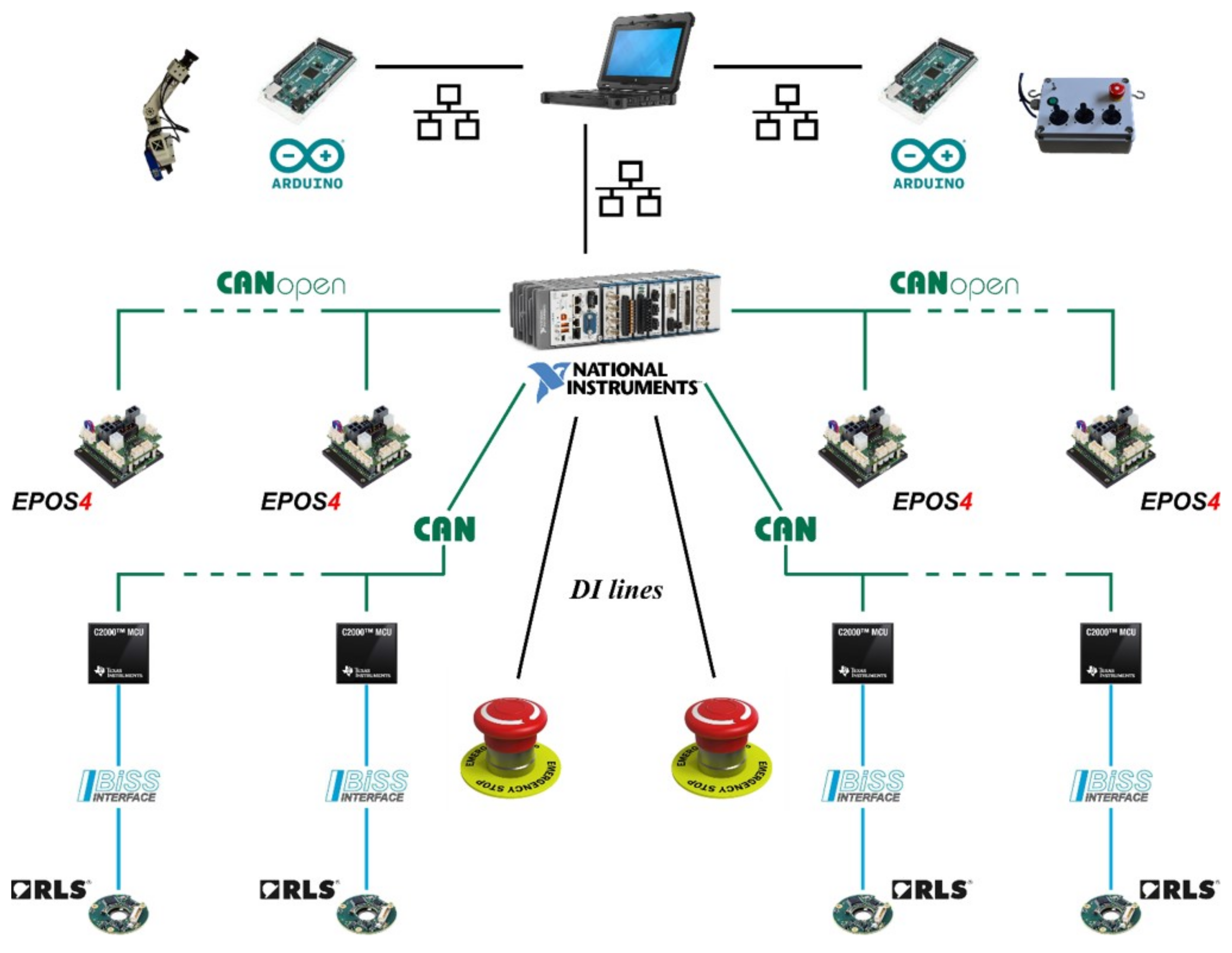
2.4. Electronic Architecture

The electronic architecture developed for this application is based on National Instrument CompactRIO system, which consists of a processor running a Linux real-time operating system and a chassis that contains a user-programmable FPGA. On the FPGA, the low level control logic and communication protocol are implemented using external modules to read sensors data and send the actuators command. The magnetic absolute encoders mentioned in Section 2.3.1 and Section 2.3.2 transmit data through BiSS-C, a serial point-to-point communication protocol. Since the point-to-point communication requires a cable for each node in the network, the data of each encoder are acquired by a Texas Instrument Tiva C TM4C123GH6PM microcontroller, positioned at joint level, with a sampling rate of 16 , 667 Hz. This removes the need for individual wiring of each encoder into the full arm. The acquired data are filtered and processed to numerically estimate the joint velocity. The microcontrollers are connected in daisy chain and transmit the joint position and velocity to the FPGA of the CompactRIO through a CAN Bus with a sample rate of 400 Hz. A second and independent CAN Bus is implemented to establish the communication with the motor drivers. In this case, the standard CANopen protocol is employed to read the motor states and send the commands. Moreover, two microcontrollers ATmega2560, provided by Atmel, are connected to the host PC through TCP/IP protocol. One of these microcontrollers manages the motors that control the pan and tilt mechanism, while the other receives the commands from a custom-made remote controller to manually drive the end-effector. The real-time target manages the communication with both the FPGA and the host PC where a graphical user interface is implemented to drive the robot and log the data. Figure 10 shows a schematic of the electronic architecture employed in this work.

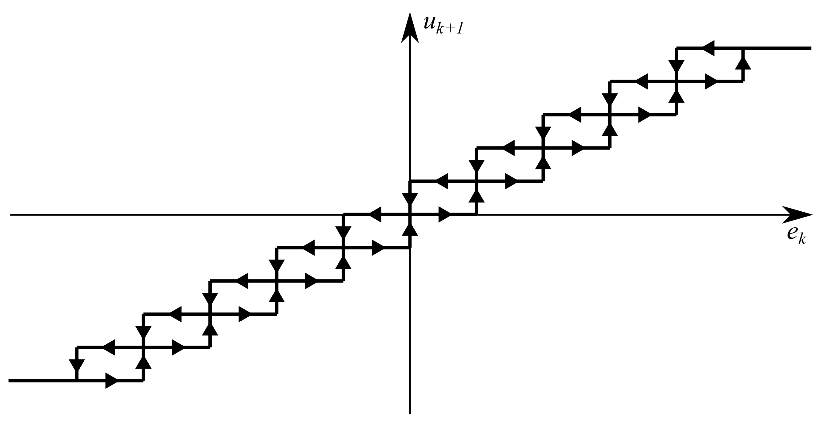
2.5. Control Strategy

This article focuses on presenting the mechanical design of a novel inspection long-reach cable-driven hyper-redundant robot to confirm its hardware feasibility. Hence, the strategy implemented to control the robot motion, including both the trajectory definition and the control algorithm, is briefly described here, leaving the stability and performances analyses as future works. The control strategy aims to follow a specific trajectory in the task space, avoiding obstacles and satisfying joint limits. First, the desired joint trajectory is computed offline using an inverse kinematic algorithm based on a null-space approach [34]. The primary task is the joint limits satisfaction, the secondary objective is obstacles avoidance, and the tertiary goal is to follow the desired trajectory in the task space. The general formulation for a null-space inverse differential kinematic problem is written as:
q ˙ = J 1 v 1 + I J 1 J 1 J 2 v 2 + I J 1 J 1 I J 2 J 2 J 3 v 3 ,
where q ˙ is the joints velocity vector, v i is the desired velocity associated to each task, and J i is the Jacobian mapping the joint velocity into the ith task velocity. The joints limit avoidance is performed by defining J 1 as a diagonal activation matrix such that
J 1 i , i = 1 if q i q i m a x 0 otherwise ,
and the element of v 1 as
v 1 i = q ˙ l i if q i < q i m a x q ˙ l i else if q i > q i m a x 0 otherwise ,
where q i m a x defines the maximum ith joint angle and q ˙ l i is the desired velocity which allows the joint to move into its range of motion. The obstacle avoidance task firstly requires that the obstacle geometry and properties be defined. Each obstacle is modelled as a sphere with centre p c and radius r o . Introducing p o as the point of the robot at the minimum distance from the obstacle, and the versor,
n o = p o p c p o p c ,
it is possible to define:
J 2 = n o T J p o ,
where J p o is the Jacobian matrix associated to p o . The parameter v 2 is the norm of the desired Cartesian velocity of p o that allows the robot to move away from the obstacle. Finally, J 3 and v 3 represent the Jacobian matrix and the desired velocity of the end-effector, respectively. Once the desired trajectory is defined, a non-linear controller is implemented to deal with the elasticity and friction effects introduced by cable-driven actuation. The proposed algorithm exploits the hysteresis phenomenon to reject the sinusoidal disturbance that may lead to system instability, i.e., the velocity output is constant if the error input remains within a specific range, avoiding an oscillating command for the actuators. Figure 11 shows the input-output chart of the controller, while the pseudo-code of the algorithm is reported in Algorithm 1. For each joint, the controller takes as input the angular error, e k , and returns, as output, the reference velocity for the driver of the actuator, u k + 1 . The discretisation step, n d , and the angular error parameter, e m a x , were empirically estimated, while v m a x is the maximum allowed actuator velocity. Firstly, the control algorithm discretises all the possible values of the output in velocity and stores them in a vector, u . Then, for each joint at a given instant k, the algorithm checks if e k is in the range e k 1 δ e , e k 1 + δ e , where δ e = e m a x / n d , and consequently chooses the proper output u k + 1 from the u vector. The control algorithm runs on the real-time processor at a frequency of 100 Hz.
Algorithm 1: Control Algorithm
1:
k = 0
2:
n d discretisation step
3:
v m a x max actuator velocity
4:
δ v = v m a x / n d
5:
u = v m a x , v m a x + δ v , , v m a x δ v , v m a x
6:
e k angular error
7:
e m a x angular error s. t. e k e m a x u k + 1 = v m a x
8:
δ e = e m a x / n d
9:
i k = 0                  { i k is the index of the vector u }
10:
whileApplication Rundo
11:
   i t = floor e k / δ e
12:
  if i t > i k then
13:
    i k + 1 = i k + 1          {if e k > e k 1 + δ e , then u k + 1 = u i k + 1 }
14:
  else if i t < i k 1 then
15:
    i k + 1 = i k 1          {if e k < e k 1 δ e , then u k + 1 = u i k 1 }
16:
  else
17:
    i k + 1 = i k         {if e k e k 1 δ e , e k 1 + δ e , then u k + 1 = u i k }
18:
  end if
19:
   i k + 1 = i k + 1 + n d
20:
  if i k + 1 > 2 n d then
21:
    i k + 1 = 2 n d                {upper bound on u elements}
22:
  end if
23:
  if i k + 1 < 0 then
24:
    i k + 1 = 0                 {lower bound on u elements}
25:
  end if
26:
   u k + 1 = u i k + 1
27:
   k = k + 1
28:
end while

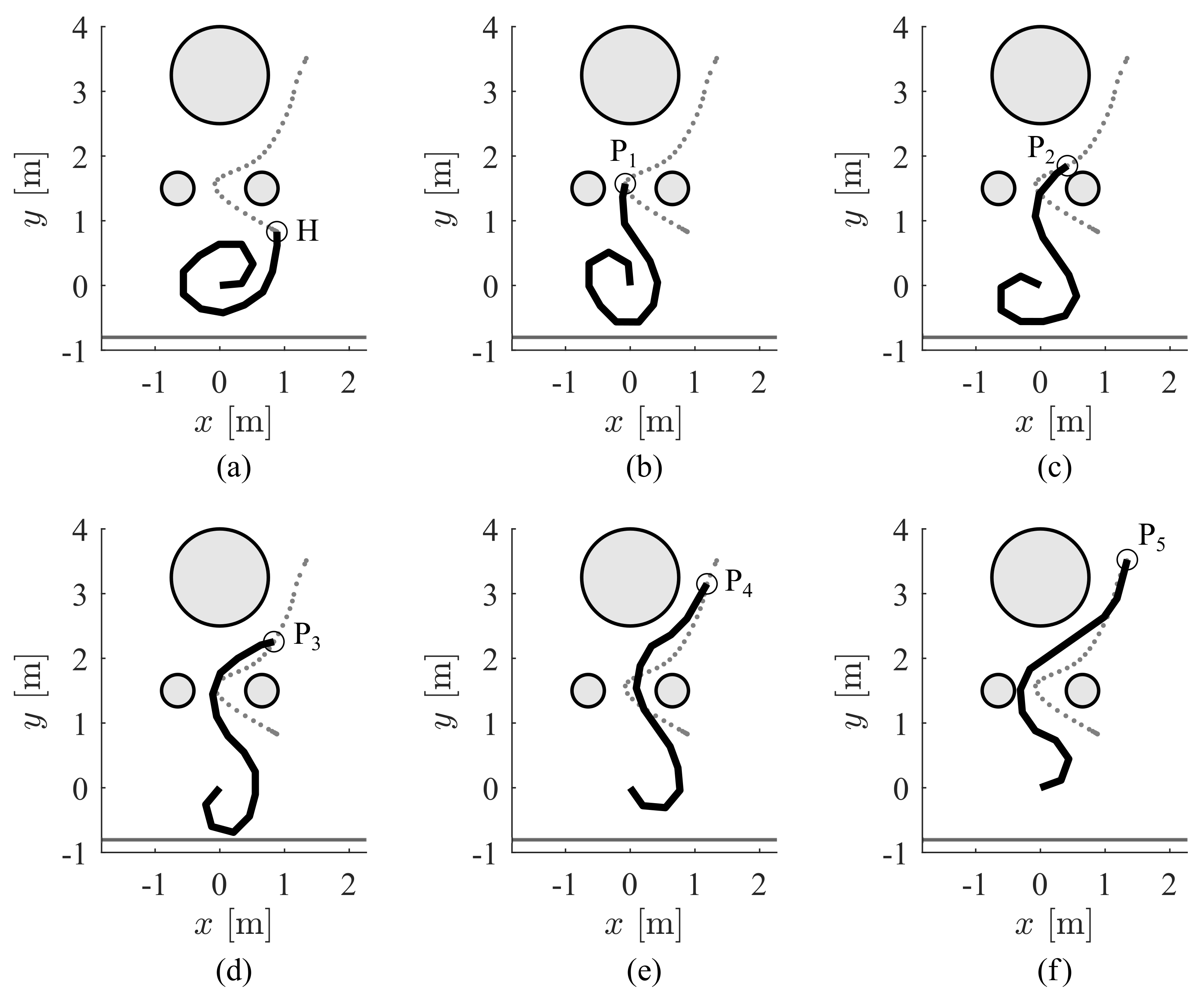
2.6. Simulation and Experiment

To analyse the performances and the capabilities of the robot, a trajectory in the open air that emulates an inspection task was designed and simulated in MATLAB® 2019b. The task consists of performing a visual inspection of some points of interest, avoiding a circular obstacle and passing through a narrow entrance. Given a reference frame fixed to the robot base and whose origin is on J 1 , as shown in Figure 2, the centre of the obstacle is located at 0 m , 3.25 m and its radius is 0.75 m. The entrance is modelled as two circular obstacles, both of which have a radius of 0.25 m and whose centres are located at 0.65 m , 1.5 m and 0.65 m , 1.5 m , respectively. The ground is modelled as a line located at y = 0.8 m. The points of interest are the following: P 1 = 0.076 m , 1.572 m , P 2 = 0.414 m , 1.850 m , P 3 = 0.836 m , 2.257 m , P 4 = 1.186 m , 3.151 m , and P 5 = 1.343 m , 3.525 m . Figure 12 shows the environment, the robot initial configuration, and the simulation of the robot in the configurations to inspect the points of interest. Once the simulation confirmed the feasibility of the trajectory, the same task was performed at an industrial site using the SLIM robot. The robot was subject to the same external conditions found in a real environment but did not enter the high temperature containment vessel. Figure 13 shows pictures of the robot performing the inspection task on-sight at an industrial facility.

3. Results

This Section reports the results of the experiment performed with the physical prototype of SLIM. During the experiment, the data regarding the tracking error were collected. The histogram of the norm of the tracking error is reported in Figure 14. The corresponding distribution is described by the following parameters:
  • mean value: 0.038 m;
  • median value: 0.025 m;
  • standard deviation: 0.035 m.
The errors in terms of position and attitude measured on each of the target poses were always within the uncertainty margins due to the sensors. Given the information on the data sheets of the AkSim2 absolute encoders and the Herkulex DRS-0602 servomotors and considering the deformation on the modules length computed via FEM analysis, the position accuracy on the TCP is σ p = 0.003 m, while the attitude accuracy on the TCP is σ α = 0.006 rad, σ β = 0.005 rad, and σ γ = 0.005 rad, where α , β , and γ are the Euler angles in the Y X Y representation.

4. Discussion

The results of the experiment show that SLIM can reach a desired TCP pose with an accuracy of 0.003 m in position and 0.006 rad in attitude. At the same time, SLIM is less accurate in following the desired trajectory between two targets. Indeed, 95 % of the time the norm of the tracking error is below 0.109 m, but it locally varies up to 0.225 m. Since the robotic arm has a length up to 4.8 m, such performances are considered acceptable. Furthermore, given the value of the tracking error and the dimensions of the modules section (≈ 0.1 m × 0.2 m), the requirement of entering through small apertures ( 40 cm × 40 cm) is fulfilled 95 % of the time. To fully satisfy the requirement, some improvements in the design and the control strategy are needed to increase the accuracy in the trajectory tracking.
Moreover, some aspects of the mechanical design were driven by the available machining techniques. Consequently, the design could be improved in terms of mass reduction and stiffness increase by implementing weldings instead of screws and substituting the tie-rods with a cover in carbon fiber.
Finally, the chosen materials and components for the robotic arm make SLIM suitable for the inspection of harsh environments characterised by high temperatures. The end-effector, instead, is a prototype that does not respect the temperature requirement. Therefore, a new version of the end-effector able to tolerate temperatures up to 100 C is needed to meet all the requirements.

5. Conclusions

In this article, a novel long-reach cable-driven hyper-redundant robot for industrial inspection, SLIM, to be used in access denied hostile environments, is described. SLIM is composed of a fixed base that houses an actuation box, able to rotate, connected to a 12 DOFs robotic arm on whose tip is installed a pan and tilt mechanism. The robotic arm is made of 12 modules, each of them composed of a revolute joint and a link. The actuation box contains the linear actuators that drive the robotic arm via cables. The pan and tilt mechanism that acts as end-effector moves a camera. For the task of positioning the camera in a bi-dimensional Cartesian space with a specific attitude, SLIM has 10 degrees of redundancy that allow it to move along complex paths, pass through small entrances, and avoid obstacles inside the area being inspected. SLIM exploits the properties of synthetic fiber cables to reduce the overall mass and keep the actuators safe from the possible extreme environmental conditions of the inspection site. The mechanical design proposed for SLIM was validated through FEM analyses. A simulated industrial environment was developed to verify the SLIM capabilities in terms of moving in complex scenarios. First, a simulation of the task was performed. Then, the real robot was tested in a reconstructed industrial environment. The obtained results are promising and pave the way to developing a future variant that will further improve the system.

Author Contributions

Project coordination, C.C.; Mechanical design and structural simulation P.G., R.G. and G.S.; software development and test, A.P., D.L. and L.D.M.C.D.V.; the project has been conducted in the Advanced Robotics line of IIT lead by D.G.C. All authors have read and agreed to the published version of the manuscript.

Funding

This research has been partially funded by Ansaldo Energia S.p.a.

Institutional Review Board Statement

Not applicable.

Informed Consent Statement

Not applicable.

Conflicts of Interest

The authors declare no conflict of interest The funders had no role in the design of the study; in the collection, analyses, or interpretation of data; in the writing of the manuscript, or in the decision to publish the results.

Abbreviations

The following abbreviations are used in this manuscript:
SLIMSnake-Like manipulator for Inspection and Maintenance operations
DOFsDegrees Of Freedom
TCPTool Centre Point

References

  1. Pistone, A.; Canali, C.; Gloriani, C.; Leggieri, S.; Guardiani, P.; Caldwell, D. Reconfigurable inspection robot for industrial applications. Procedia Manuf. 2019, 38, 597–604. [Google Scholar] [CrossRef]
  2. Leggieri, S.; Canali, C.; Cannella, F.; Lee, J.; Caldwell, D.G. Preliminary Study on the Crawler Unit of a Novel Self-Reconfigurable Hybrid Platform for Inspection. In Proceedings of the 2021 20th International Conference on Advanced Robotics (ICAR), Ljubljana, Slovenia, 6–10 December 2021; pp. 77–82. [Google Scholar] [CrossRef]
  3. Martelli, S.; Mazzei, L.; Canali, C.; Guardiani, P.; Giunta, S.; Ghiazza, A.; Mondino, I.; Cannella, F.; Murino, V.; Del Bue, A. Deep Endoscope: Intelligent Duct Inspection for the Avionic Industry. IEEE Trans. Ind. Inform. 2018, 14, 1701–1711. [Google Scholar] [CrossRef]
  4. Guardiani, P.; Canali, C.; Pistone, A.; Leggieri, S.; Gloriani, C.; Rahman, N.; Cannella, F.; Caldwell, D. Novel Integrated Robotic System for Tiny Duct Inspection. Procedia Manuf. 2018, 17, 342–349. [Google Scholar] [CrossRef]
  5. Houlihan, B. Europe’s ageing infrastructure: Politics, finance and the environment. Util. Policy 1994, 4, 243–252. [Google Scholar] [CrossRef]
  6. Morimoto, R. Estimating the benefits of effectively and proactively maintaining infrastructure with the innovative Smart Infrastructure sensor system. Socio-Econ. Plan. Sci. 2010, 44, 247–257. [Google Scholar] [CrossRef]
  7. Chirikjian, G.S.; Burdick, J.W. An obstacle avoidance algorithm for hyper-redundant manipulators. In Proceedings of the IEEE International Conference on Robotics and Automation, Cincinnati, OH, USA, 13–18 May 1990; pp. 625–631. [Google Scholar] [CrossRef] [Green Version]
  8. Hannan, M.W.; Walker, I.D. Analysis and initial experiments for a novel elephant’s trunk robot. In Proceedings of the 2000 IEEE/RSJ International Conference on Intelligent Robots and Systems (IROS 2000) (Cat. No.00CH37113), Takamatsu, Japan, 31 October–5 November 2000; Volume 1, pp. 330–337. [Google Scholar] [CrossRef]
  9. Cieślak, R.; Morecki, A. Elephant trunk type elastic manipulator—A tool for bulk and liquid materials transportation. Robotica 1999, 17, 11–16. [Google Scholar] [CrossRef]
  10. Guglielmino, E.; Tsagarakis, N.; Caldwell, D.G. An octopus anatomy-inspired robotic arm. In Proceedings of the 2010 IEEE/RSJ International Conference on Intelligent Robots and Systems, Taipei, Taiwan, 18–22 October 2010; pp. 3091–3096. [Google Scholar] [CrossRef]
  11. Hirose, S. Biologically Inspired Robots: Snake-like Locomotors and Manipulators; Oxford University Press: Oxford, UK, 1993. [Google Scholar]
  12. Buckingham, R.O.; Graham, A.C. Dexterous manipulators for nuclear inspection and maintenance—Case study. In Proceedings of the 2010 1st International Conference on Applied Robotics for the Power Industry, Montreal, QC, Canada, 5–7 October 2010; pp. 1–6. [Google Scholar] [CrossRef]
  13. HiBot. ACM-R5H. Available online: https://www.hibot.co.jp (accessed on 31 January 2022).
  14. Abidi, H.; Gerboni, G.; Brancadoro, M.; Fras, J.; Diodato, A.; Cianchetti, M.; Wurdemann, H.; Althoefer, K.; Menciassi, A. Highly dexterous 2-module soft robot for intra-organ navigation in minimally invasive surgery. Int. J. Med Robot. Comput. Assist. Surg. 2018, 14, e1875. [Google Scholar] [CrossRef] [PubMed]
  15. Simaan, N.; Xu, K.; Wei, W.; Kapoor, A.; Kazanzides, P.; Taylor, R.; Flint, P. Design and Integration of a Telerobotic System for Minimally Invasive Surgery of the Throat. Int. J. Robot. Res. 2009, 28, 1134–1153. [Google Scholar] [CrossRef] [PubMed]
  16. Pedemonte, N.; Rasheed, T.; Marquez-Gamez, D.; Long, P.; Hocquard, É.; Babin, F.; Fouché, C.; Caverot, G.; Girin, A.; Caro, S. Fastkit: A mobile cable-driven parallel robot for logistics. In Advances in Robotics Research: From Lab to Market; Springer: Berlin/Heidelberg, Germany, 2020; pp. 141–163. [Google Scholar] [CrossRef]
  17. Qian, S.; Zi, B.; Shang, W.-W.; Xu, Q.-S. A Review on Cable-driven Parallel Robots. Chin. J. Mech. Eng. 2018, 31, 1–11. [Google Scholar] [CrossRef]
  18. Buckingham, R.O.; Graham, A.C. Link Assembly for a Snake Like Robot Arm. U.S. Patent 7,543,518, 9 June 2009. [Google Scholar]
  19. Dong, X.; Raffles, M.; Cobos-Guzman, S.; Axinte, D.; Kell, J. A Novel Continuum Robot Using Twin-Pivot Compliant Joints: Design, Modeling, and Validation. J. Mech. Robot. 2015, 8, 021010. [Google Scholar] [CrossRef]
  20. Gargiulo, L.; Bayetti, P.; Bruno, V.; Hatchressian, J.C.; Hernandez, C.; Houry, M.; Keller, D.; Martins, J.P.; Measson, Y.; Perrot, Y.; et al. Operation of an ITER relevant inspection robot on Tore Supra tokamak. Fusion Eng. Des. 2009, 84, 220–223. [Google Scholar] [CrossRef]
  21. Endo, G.; Horigome, A.; Takata, A. Super Dragon: A 10-m-Long-Coupled Tendon-Driven Articulated Manipulator. IEEE Robot. Autom. Lett. 2019, 4, 934–941. [Google Scholar] [CrossRef]
  22. Marjaninejad, A.; Urbina-Meléndez, D.; Cohn, B.A.; Valero-Cuevas, F.J. Autonomous functional movements in a tendon-driven limb via limited experience. Nat. Mach. Intell. 2019, 1, 144–154. [Google Scholar] [CrossRef] [PubMed] [Green Version]
  23. Laffranchi, M.; Boccardo, N.; Traverso, S.; Lombardi, L.; Canepa, M.; Lince, A.; Semprini, M.; Saglia, J.; Naceri, A.; Sacchetti, R.; et al. The Hannes hand prosthesis replicates the key biological properties of the human hand. Sci. Robot. 2020, 5, eabb0467. [Google Scholar] [CrossRef] [PubMed]
  24. Guardiani, P.; Ludovico, D.; Pistone, A.; Abidi, H.; Zaplana, I.; Lee, J.; Caldwell, D.G.; Canali, C. Design and Analysis of a Fully Actuated Cable-Driven Joint for Hyper-Redundant Robots With Optimal Cable Routing. J. Mech. Robot. 2021, 14, 021006. [Google Scholar] [CrossRef]
  25. Ludovico, D.; Guardiani, P.; Pistone, A.; Lee, J.; Cannella, F.; Caldwell, D.G.; Canali, C. Modeling Cable-Driven Joint Dynamics and Friction: A Bond-Graph Approach. In Proceedings of the 2020 IEEE/RSJ International Conference on Intelligent Robots and Systems (IROS), Las Vegas, NV, USA, 24 October–24 January 2021; pp. 7285–7291. [Google Scholar] [CrossRef]
  26. Coulibaly, J.B.; Chanut, M.A.; Lambert, S.; Nicot, F. Sliding cable modeling: An attempt at a unified formulation. Int. J. Solids Struct. 2018, 130, 1–10. [Google Scholar] [CrossRef]
  27. Miyasaka, M.; Matheson, J.; Lewis, A.; Hannaford, B. Measurement of the cable-pulley Coulomb and viscous friction for a cable-driven surgical robotic system. In Proceedings of the 2015 IEEE/RSJ International Conference on Intelligent Robots and Systems (IROS), Hamburg, Germany, 28 September–2 October 2015; pp. 804–810. [Google Scholar] [CrossRef]
  28. Dwivedy, S.K.; Eberhard, P. Dynamic analysis of flexible manipulators, a literature review. Mech. Mach. Theory 2006, 41, 749–777. [Google Scholar] [CrossRef]
  29. Ludovico, D.; Pistone, A.; De Mari Casareto Dal Verme, L.; Guardiani, P.; Caldwell, D.G.; Canali, C. Static Elasticity Compensation via Recursive Artificial Neural Network for Long-Reach Cable-Driven Hyper-Redundant Manipulators. In Proceedings of the 2021 20th International Conference on Advanced Robotics (ICAR), Ljubljana, Slovenia, 6–10 December 2021; pp. 1116–1120. [Google Scholar] [CrossRef]
  30. Mahlin, M.; Wagner, R.L.; Dorsey, J.; Jones, T.C. Tendon-Actuated Lightweight In-Space MANipulator (TALISMAN) Hinge Joint Structural. In Proceedings of the ASCEND 2020, Virtual Event, 16–18 November 2020; p. 4251. [Google Scholar] [CrossRef]
  31. Khalil, W.; Dombre, E. Modeling, Identification and Control of Robots; Butterworth-Heinemann, Kogan Page Science: London, UK, 2004. [Google Scholar]
  32. Horigome, A.; Endo, G. Investigation of repetitive bending durability of synthetic fiber ropes. IEEE Robot. Autom. Lett. 2018, 3, 1779–1786. [Google Scholar] [CrossRef] [Green Version]
  33. Inc, Samson Rope Technology Samson Splicing Instructions. 2006. Available online: www.samsonrope.com (accessed on 23 March 2022).
  34. Mansard, N.; Khatib, O.; Kheddar, A. A unified approach to integrate unilateral constraints in the stack of tasks. IEEE Trans. Robot. 2009, 25, 670–685. [Google Scholar] [CrossRef]
Figure 1. Possible inspection scenarios: (a) moving around obstacles (b) entering through a small entrance (c) under-ground inspection (d) wall side inspection.
Applsci 12 03348 g001
Figure 2. CAD drawing of the robotic system.
Applsci 12 03348 g002
Figure 3. The whole robotic system in its parking position that is enclosed within a volume whose dimensions are 152 cm × 88 cm × 158 cm L × W × H .
Applsci 12 03348 g003
Figure 4. Details of a single module and its integration into the full 12 modules of the robotic arm.
Applsci 12 03348 g004
Figure 5. Detail of the spliced Zylon PBO cable connected to the anchor and tensioning system.
Applsci 12 03348 g005
Figure 6. Results of the FEM analysis on the 1st module of the robotic arm. (a) shows the forces and constraint reaction forces acting on the module; (bd) show the total resulting deformation in mm from different points of view, with a deformation scale factor equal to 71.
Applsci 12 03348 g006
Figure 7. CAD drawing of the linear actuator.
Applsci 12 03348 g007
Figure 8. Schematic view of the actuation system. For each joint a couple of counteracting cables are routed from a linear actuator on the base up to a pulley along the robotic arm.
Applsci 12 03348 g008
Figure 9. Pan and tilt mechanism together with the camera.
Applsci 12 03348 g009
Figure 10. Electronic architecture of the robot.
Applsci 12 03348 g010
Figure 11. Control algorithm input output relation.
Applsci 12 03348 g011
Figure 12. Simulation of SLIM performing the above–described inspection task. (a) shows SLIM at its initial configuration, H; (b) shows SLIM at P 1 ; (c) shows SLIM at P 2 ; (d) shows SLIM at P 3 ; (e) shows SLIM at P 4 ; (f) shows SLIM at P 5 .
Applsci 12 03348 g012
Figure 13. Pictures of SLIM performing the inspection task. (a) shows SLIM at P 1 ; (b) shows SLIM at P 2 ; (c) shows SLIM at P 4 .
Applsci 12 03348 g013
Figure 14. Histogram of the norm of the tracking error. The vertical axis indicates the relative probability of each histogram bin.
Applsci 12 03348 g014
Table 1. DH parameters for SLIM.
Joint a i [mm] α i [rad] d i [mm] θ i [rad]
Arm and Base
10 π / 2 0 q 1 + 0.028 π
2 339.3 00 q 2 0.028 π
335000 q 3
1335000 q 13 + π / 2
End-Effector
140 π / 2 410 q 14
150 π / 2 0 q 15 π / 2
Camera
TCP212 π / 2 00
Table 2. Robotic arm parameters for SLIM.
M 1 M 2 M 3 M 4 M 5 M 6 M 7 M 8 M 9 M 10 M 11 M 12 Unit
m22 1.65 1.65 1.3 1.3 11 0.78 0.78 0.66 0.66 kg
C o M x 109109108108109109109109105105112112mm
l350350350350350350350350350350350350mm
r555555555555555555555555mm
w228228222222222222214214211211209209mm
h112112112112107107107107107107107107mm
Table 3. Comparison between steel and Zylon PBO cables.
SteelZylon PBOUnit
Diameter33mm
Density38.56.5g/mm
Max load5.712.6kN
Max temperature1500650 C
Publisher’s Note: MDPI stays neutral with regard to jurisdictional claims in published maps and institutional affiliations.

