Article

Design of the Crawler Units: Toward the Development of a Novel Hybrid Platform for Infrastructure Inspection

1
Department of Advanced Robotics (ADVR), Italian Institute of Technology, 16163 Genoa, Italy
2
Department of Engineering and Applied Sciences, University of Bergamo, 24044 Dalmine, Italy
*
Author to whom correspondence should be addressed.
Appl. Sci. 2022, 12(11), 5579; https://doi.org/10.3390/app12115579
Submission received: 27 April 2022 / Revised: 25 May 2022 / Accepted: 26 May 2022 / Published: 31 May 2022
(This article belongs to the Special Issue Smart Robots for Industrial Applications)

Abstract

:
Inspections of industrial and civil infrastructures are necessary to prevent damages and loss of human life. Although robotic inspection is gaining momentum, most of the operations are still performed by human workers. The main limiting factors of inspection robots are the lack of versatility as well as the low reliability of these devices, since they need to operate in a non-structured environment. In this work, a novel Hybrid Platform for inspection in industrial contexts is proposed, focusing on the design and testing of the Crawler Unit. The goal is to solve versatility related issues exploiting modularity and self-reconfigurability. The Hybrid Platform consists of three main systems: a mobile Main Base and two Crawler Units. Each would operate independently, accomplishing specific tasks. Docking interfaces, on each device, allow the systems to reconfigure into different robots. The Crawler Unit operates in constrained environments and narrow spaces. The Main Base patrols wide areas and deploys the Crawler Units near the inspection site. For dealing with challenging conditions, the two Crawler Units can dock together, reconfiguring into a snake-like robot. Additionally, once docked to the Main Base, the two Crawlers can operate also as robotic arms, providing manipulation abilities to the platform. The first version of the Crawler Unit exhibited an interesting performance over flat and uneven terrains. To extend the mobility of this robot, a second version was developed, introducing some innovations in the system design. These innovations provided the Crawler Unit with advanced mobility in the vertical plane, thus allowing the robot to deal with more complex scenarios such as crossing gaps, overcoming obstacles and lifting the modules.

1. Introduction

Regular inspection and maintenance operations are crucial to meet safety regulations and to ensure efficient functioning of machines and structures, reporting issues before problems become critical. This is particularly true in power plants, Oil & Gas industries and civil infrastructures, where unexpected failures or breakages may lead to catastrophic events and potential loss of life. In addition, such assets may require an extraordinary monitoring in response to unexpected natural events or when malfunctions and alarms occur. In this perspective, the spread of inspection robots represents an important technological breakthrough. These robots are designed with the primary goal of minimizing the risks related to the involvement of humans in such dangerous and repetitive tasks. Ground inspection robots can be roughly divided into two families according to their main purpose: general inspection and the monitoring and inspection of specific equipment.
During general inspection, the robots span extensive areas in order to reach the target, such as pipes, pumps, valves, tanks, etc. Often, such systems consist of wheeled [1] or tracked [2] platforms equipped with sensors and robotic arms. Narrow spaces, slopes and stairs are still open challenges that require more advanced devices [3,4].
Within industrial plants, some assets require thorough inspections, i.e., external and internal. Therefore, many specialized robots, [5,6], have been developed to cover these critical components. To accomplish the task, these devices exhibit small-sized and target-oriented designs [7,8,9].
Pipe inspection robots have to traverse long distances in highly constrained environments. For locomotion, mainly wheels or tracks are used, [10,11]. However, pipelines result from the combination of many segments; therefore, snake robots are gaining momentum in this context, see [12,13,14].
Although the robots discussed so far display interesting design solutions, these systems still present some important limitations. For instance, general inspection robots are often big platforms, and this also represents their main weakness. The robotic arms equipped may help in accessing difficult-to-reach targets; however, the inspection workspace is constrained by the platform dimensions, since the arms cannot detach. On the other hand, most of the specialized devices rely on human operators for the deployment phase. However, requiring the presence of workers near the inspection site conflicts with one of the primary goal of inspection robots, i.e., to limit/reduce the presence of human operators in situ. An interesting technology is represented by the so-called marsupial robots, where the main platform houses and releases smaller devices for inspecting the hardest-to-reach places [15,16,17].
In the wake of marsupial robots, we started to develop a new self-reconfiguring Hybrid Platform, which combines different robots in order to maximize the application range of our system. In particular, we focused on the design and testing of the Crawler Unit.

2. Materials and Methods

This section reports the design principles and the possible applications for our novel Hybrid Platform. In particular, the focus is on the mechanical features of the Crawler Unit and on the differences between the two versions developed. This section ends with an insight on the electronic architecture and the control algorithm.

2.1. The Hybrid Platform Overview

The main idea is to take advantage of modularity and self-reconfigurability to design a new versatile multi-purpose Hybrid Platform, which will consist of three systems: a mobile Main Base and two twin Crawler Units, as shown in Figure 1. These robots are designed to perform inspections either independently or in collaboration, as described in [18,19]. Thanks to the small size, the two Crawler Units are especially suitable for inspection in constrained or cluttered environments and narrow spaces, as discussed in [20,21]. On the contrary, the Main Base presents a larger size than the Crawler Units in order to cover long distances as fast as possible. Therefore, such a system is more effective in patrolling and monitoring wide areas, such as the aforementioned plant inspection robots.
Whenever the inspection target or the surroundings are too complex to reach or too challenging to deal with a single robot, the systems can reconfigure autonomously without requiring direct human intervention. In this way, a human operator can tele-operate the system, limiting the risks of being in close proximity of inspection targets. For instance, the Crawler Units can dock together forming a snake robot, see Figure 1. Assuming this configuration, the system can deal with complex operations such as: reaching components placed in higher places, climbing stairs, or crossing very rough terrains. In addition, the Crawler Units can couple with the Main Base, turning the Hybrid Platform into a dual arm system that can execute manipulation and maintenance tasks, as shown in Figure 1. Adopting such a configuration, the Main Base becomes a true marsupial system, which can carry, deploy and recover the Crawler Units near and from different inspection sites. Ultimately, this Hybrid Platform provides the end user with a suite of systems capable of dealing with multiple tasks that span from the inspection of confined spaces to the monitoring of an entire plant, passing through the exploration of hard-to-reach areas or, eventually, the manipulation of small objects. To develop such a versatile system, the design of the Crawler Units assumes particular relevance.

2.2. The Crawler Unit: Overview

Referring to Figure 2, each Crawler Unit consists of three main bodies plus the docking module. Each module is connected with the subsequent through an active kinematic chain with 3 degrees of freedom (DoFs).
The Crawler Unit equips a combination of active and passive tracks for locomotion. In particular, the tracks on the two longest modules are active, while the others are passive. The single DC motor concurrently drives the tracks on both sides of active modules. For turning, the Crawler can adopt two configurations: the C-configuration and the S-configuration. In the former, the Crawler rotates the modules in the same direction using the yaw joints, and the system assumes a configuration similar to the letter C. When the active tracks spin in the same direction, the Crawler begins to turn with a given curvature radius. In the S-configuration, the Crawler rotates the modules in opposite directions using the yaw joints; the robot assumes a configuration similar to the letter S. When the active tracks spin in opposite directions, the Crawler starts to turn on the spot.
The system is redundant either in kinematics and actuation. Kinematic redundancy confers great adaptability to different terrains and obstacles. Kinematic redundancy is crucial when the Crawler Unit operates as a ground robot in unknown environments, and when the Crawler Unit attaches to the Main Base and reconfigures into a robotic arm. Actuation redundancy ensures an additional degree of fault-tolerance and reliability to the Crawler Unit.
Two prototypes of the Crawler Unit have been developed, see Figure 3. Both the models have similar macroscopic features, e.g., number of modules, kinematics, tracks. However, the two versions present some differences on specific components. Such differences will be discussed in next subsections. The modules are called from the left to the right: rear module, central module, front module and docking module. In both versions, each module has a hollow chassis to store the actuators and electronic boards that drive the system. In particular, the rear module houses the electronics, the drive system and the yaw joint actuator. In version one, the central module encloses two servomotors that act as pitch joints and it has some free space for possible payloads. In version two, however, the free space is reduced to give room to the two pitch joints and their new transmissions. The front module contains another drive system and two yaw joints, one in the front and the other in the back. Lastly, the docking module accommodates another pitch joint, the docking mechanism and its driver circuit.
Referring to Figure 3, the chassis of the modules deeply differ between versions. In particular, the Crawler frames of version two present several external ribs, and such a feature is not merely aesthetic. As a matter of fact, version one of the Crawler Unit is quite heavy as a result of the over-sizing of the mechanical parts. In developing version two, a preliminary structural analysis guaranteed that the most sensible components, such as the module chassis and the joint flanges, still could withstand the loads. Besides the aforementioned external ribs, some structural gussets and fillets are included to strengthen the chassis frame of version two. Table 1 and Table 2 summarize the parameters of version one and two of the Crawler Unit, respectively.

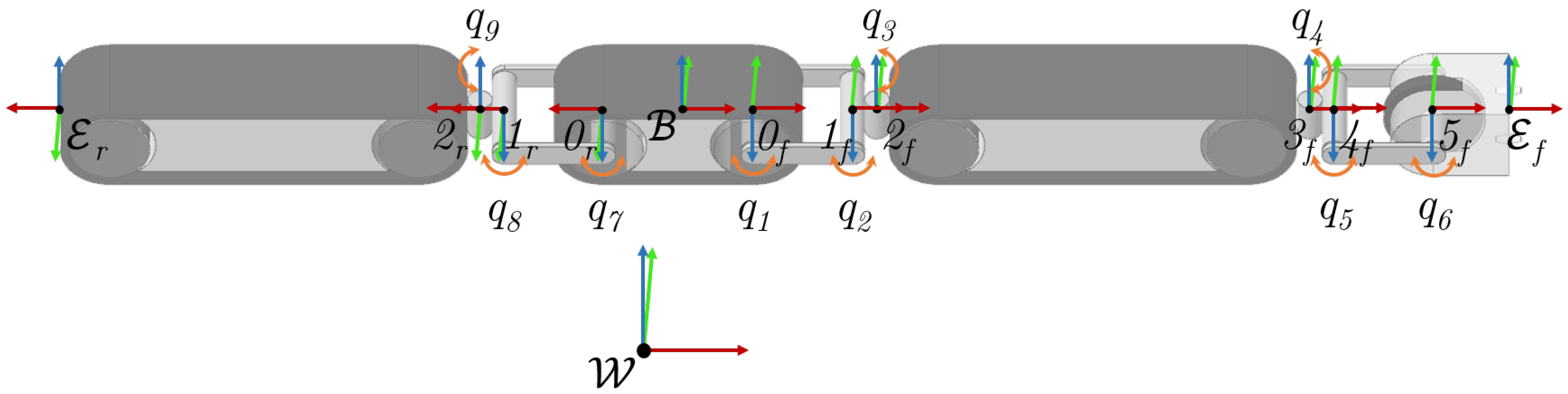
2.3. The Crawler Unit: Kinematics

The Crawler Unit kinematic representation is illustrated by Figure 4. For visual clarity, each x, y and z axis of the reference frames is distinguished using red, green and blue colors, respectively. Moreover, each joint DoF is denoted by an orange, curved arrow. The Crawler Unit is a floating base system; therefore, it would be necessary to define a fictitious 6 DoFs joint q b , which relates the position and orientation of frame B , with respect to the inertial frame W , [22,23]. However, in a purely kinematic perspective, the fictitious joint characterization is not fundamental for the definition of the Crawler Unit kinematics. For convenience, the local frame B is fixed on the central module center of mass (CoM). The Crawler Unit is modeled assuming its modules as belonging to two serial kinematics originating from frame B . Applying the Denavit–Hartenberg convention (D–H), the i 1 -th frame is attached to the i-th joint, with the local z axis parallel to the joint rotation axis. Finally, frames E f and E r identify the two Crawler Unit end effectors. Table 3 lists the D–H parameters used for modeling these two serial kinematics.
In particular, the two transformations from frame B to the frames 0 f and 0 r are static transformations. The central module length is represented by l c . The variable l l corresponds to the length of the link among two consecutive pitch joints, e.g., the distance between frame 0 f and 1 f . The variable l ρ denotes the radii sum of successive pitch and yaw joints, e.g., the distance between frame 1 f and 2 f . The parameters l f , l r and l d represent the length of the central, front, rear and docking modules, respectively. Each variable q i denotes the corresponding i-th joint angle. The vector q j = q 1 , q 2 , q 3 , q 4 , q 5 , q 6 , q 7 , q 8 , q 9 T collects the robot-generalized variables.
Figure 5 illustrates the kinematic chain that connects the central module to the rear one. Each joint is driven by a servomotor, which is equipped with a dual stage transmission in order to increase the output torque. Here, timing belts and pulleys were used to implement all the transmissions; in this way it was possible to design compact light-weight reducers. In particular, the transmissions of both pitch joints have a reduction ratio η p = 5.6 : 1 , while the transmission of the yaw joint has a reduction ratio η y = 3.8 : 1 . Referring to Figure 5, the yaw joint is completely enclosed in the module chassis. This joint assembles with the middle pitch joint with a C flange. Due to the short distance, l ρ = 0.05 m , among the axis of these two joints, such connection can be intended as a Cardan joint. The middle pitch joint is partially encapsulated into the linking element to the consecutive pitch joint. The kinematic chain ends with the pitch joint, on the right, that anchors to the central module chassis. Further details about the mechanical features of the Crawler Unit are provided in [21].

2.4. Electronics and Control

The Crawler Unit active tracks are driven by two DCX12L Maxon Motors. Each motor includes the GPX12HP planetary gearbox with reduction ratio 83 : 1 and the ENX10 EASY 256IMP encoder. Additional details are listed in Table 4. These actuators are driven by the L298N Motor Driver, which includes a dual H-Bridge chip. Such a board is controlled through PWM and digital signals generated by the microcontroller.
All the active joints of the Crawler kinematic chains are driven by the Herkulex DRS-0602 servomotors, as shown in Table 4. These servomotors are light-weight, but they produce high output torques. Additionally, the embedded electronics controls the servomotor implementing a PID logic. Once it received the desired angle, the servomotor computes the velocity profile to reach the goal smoothly. All the Herkulex servomotors are serially connected, and the communication is implemented using the TTL Full Duplex UART Serial logic. The microcontroller interacts with the servomotors exchanging request packets, which encode the required information. Here, a C++ custom library is used to interface the Herkulex servomotors with the microcontroller. Such a library defines a set of functions that build request packets and decode the acknowledgment packets, according to the communication logic.
In version one of the Crawler Unit, the user input is provided by a dual axis joystick. This configuration allows the operator to control only the horizontal mobility of the Crawler Unit. Therefore, the robot behavior is pre-determined by many control routines that have been developed to perform the ground maneuverability experiments. This arrangement was not ideal; therefore, version two of the system provides the user with an extended joypad. Referring to Figure 6, the new joypad consists of two dual axis joysticks and five push buttons. The joystick on the right controls the forward motion and the lateral motions of the module, and, instead, the joystick on the left controls the vertical motions of the modules. The control programs have been updated as well to include the additional inputs. In this way, the user had an improved control over the system during the experiments. The push buttons are wired to the microcontroller, but their features are not implemented yet. Future work will focus on the development of a good user-interface and high-level controllers that will help the end-user in piloting the Crawler Unit during field tests.
Both the Crawler Units equip the ATmega 2560 microcontrollers embedded in the Arduino Mega 2560 boards, as referred to in Table 4. The clock frequency of the microntroller is 16 MHz, and the Arduino board has to deal with many input/output signals. The FreeRTOS library is installed on the Arduino board in order to effectively manage all the signals mimicking the multi-tasking, [24]. The Arduino Mega board equips a single core microprocessor; therefore, the instructions are executed sequentially. However, the Real Time Operating System FreeRTOS implements a scheduler, which allows one to run different bits of the control code almost simultaneously. In particular, the instructions for managing each input/output are coded in separate execution threads and the scheduler executes the threads according to the priority or the presence of interrupts.
As shown in Figure 6, the Crawler Unit is powered by an umbilical cable. This cable connects the robot to a dual channels power supply, with one channel for the DC motors and the other for the servomotors. In addition, the Arduino Mega 2560 board is connected to the control computer by a USB cable.

3. Results

Both the Crawler Unit versions have been tested during lab experiments and their behaviors have been evaluated and compared. First experiments aimed at verifying the functionality of all the mechanical subsystems. Successive experiments evaluated the Crawler performance in common scenarios that can be met by the system during inspections. Many tests targeted the Crawler ground maneuverability on flat terrains. Particular relevance assumed the experiments on the Crawler Unit turning motion. Further experiments evaluated the Crawler Unit vertical mobility as well. In particular, these tests involved the system mobility assessment over ramps, uneven grounds and in the presence of ditches. Finally, experiments investigated the Crawler Unit behavior during vertical motions of the extreme modules, i.e., the docking module and the rear module.
All the experiments reported in the following subsections were performed by a human operator, which tele-operated the Crawler Unit. At first, the low clock frequency of the Arduino Mega 2560, equipped by both versions, made it impossible to read the encoders of the robots. Therefore, linear and angular velocities of the two Crawler Units were estimated dividing the distance traveled by the time spent. Later, version two was upgraded, replacing the microcontroller with the Arduino Due. With this improvement, it was possible to record feedback from the encoders and the horizontal mobility experiments were repeated. In the following, the experimental results of version one have to be accounted as qualitative estimations, whereas the horizontal performance of version two are obtained by statistical analysis of the results from 3 trials.

3.1. Forward Motion

Version one of the Crawler Unit was tested in performing a forward and backward motion on a flat terrain. This experiment aimed at verifying the effectiveness of the drive systems in concurrently driving the active tracks. Additionally, such an experiment provided preliminary data on the maximum longitudinal velocity that could be achieved. It is worth mentioning that the modular design of the Crawler allows a certain degree of customization. For instance, it is possible to replace the DC motors or the drive system transmission ratio in order to achieve higher torques or higher velocities. Referring to Figure 7, the test consisted in moving the Crawler from its starting position toward the finish line, which was placed 1 m forward. The system covered this distance in t = 10 s, achieving an estimated average velocity v = 0.1 [m/s].
As shown in Figure 8, the same experiment was repeated for version two of the Crawler Unit. From data analysis of 3 trials, it was possible to conclude that the new version demonstrated similar results. The active tracks achieved the average forward speed v = 0.107 [m/s] with standard deviation of σ = 0.002 [m/s]. The robot traveled 1 m forward in t = 9.3 s.
During these experiments, both versions demonstrated that the external polyurethane layers of the tracks did not provide a high friction coefficient over the linoleum floor. In addition, the internal friction of passive tracks was higher than expected. As a result, the passive tracks slipped on the ground rather than rotating. However, this represents a minor issue, which can be solved by coating the external layer of each track with a more adhesive material.

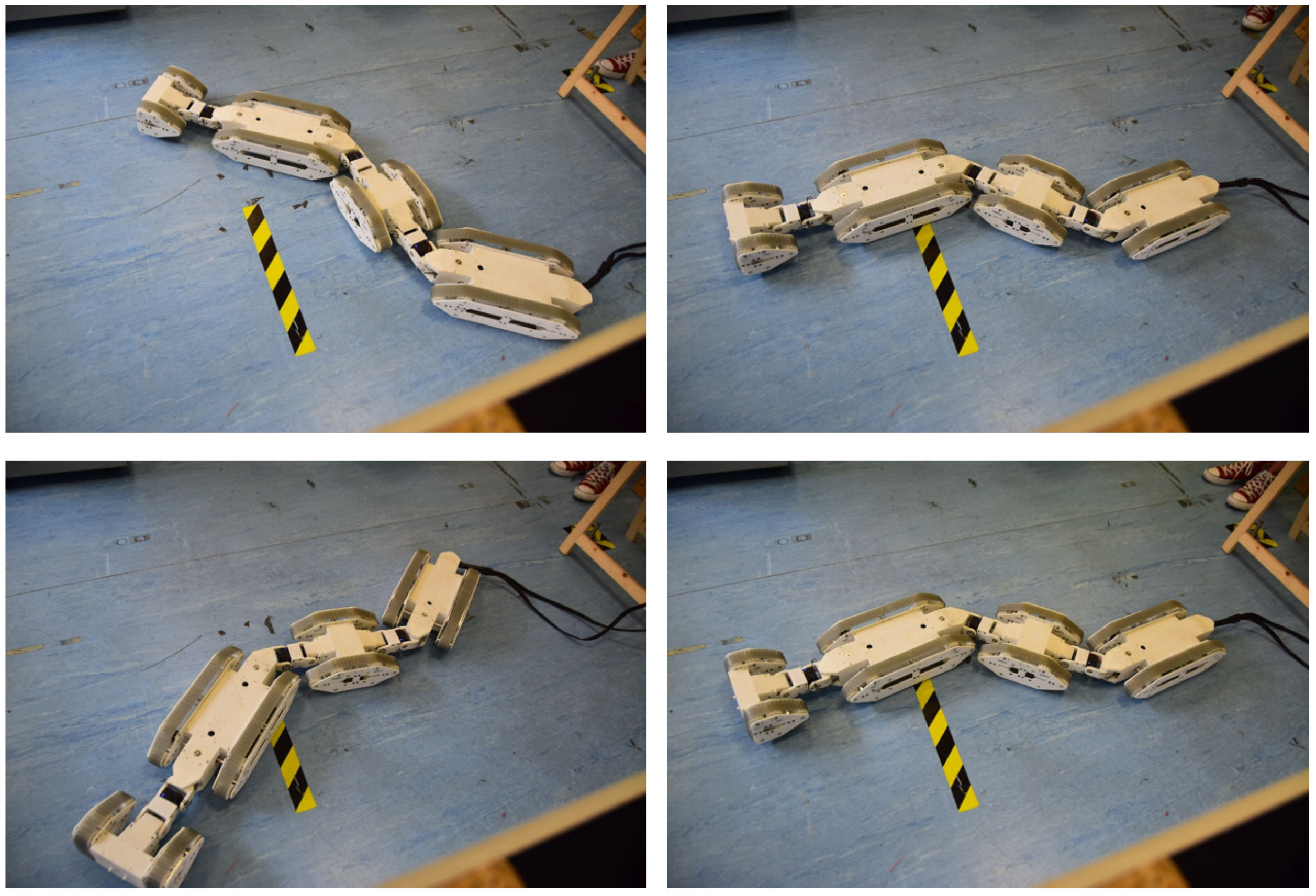
3.2. The C-Configuration

Since the tracks of each active module are concurrently driven by a single motor, the Crawler Unit cannot turn using a skid-steering technique, i.e., driving the tracks to spin in opposite directions. With this design layout, a possible way of inducing a turning motion on the Crawler Unit is by rotating the modules with the yaw joints, while the active tracks spin, as shown in Figure 9. In particular, the Crawler Unit assumed C-configurations, whose shapes were determined by the desired yaw angles. Moving the dual axis joystick from the center to the left/right directions, the operator determined how loose or sharp the Crawler Unit final configuration was and, consequently, the circular trajectory followed by the system. The curvature radius ρ depends on the lengths of the modules and on the yaw angles according to the following relation:
ρ = l 1 + l 2 cos q sin q
where q = q 3 = q 4 = q 8 represents the relative yaw angles between modules, l 1 = l c / 2 + l l + l ρ is the equivalent central module length, and l 2 = l f / 2 = l r / 2 is the front module half length. It is worth noticing that this formula holds true, provided that all the modules rotate by the same angle. According to the system dimensions, the minimum curvature radius of version one of the Crawler Unit is ρ = 0.45 m, when the yaw joints reach their limit angles ± 0.87 [rad]. Version one of the Crawler achieved an estimated angular velocity ω = 0.1 [rad/s] and rotated by about 1.57 [rad] in t = 15 s, with all yaw joints at their maximum allowed rotation of 0.87 [rad].
The same experiments were performed on version two of the Crawler Unit, as shown by Figure 10. Adopting the same configuration of version one, the performance of the new prototype slightly downgraded and the curvature radius resulted ρ = 0.6 m. This behavior was not surprising, because version two has longer modules than version one, i.e., the length l 1 is increased. In addition, the yaw joints have narrower limit angles of ± 0.7 [rad]. The data analysis demonstrated that the active tracks of version two achieved an average linear velocity v = 0.0608 [m/s] with standard deviation σ = 0.002 [m/s] and a theoretical angular velocity ω t = 0.10 [rad/s]. Accordingly, the robot rotated by about 1.57 [rad] in t = 17 s, achieving an estimated angular velocity ω e = 0.09 [rad/s], when all yaw joints were at their limit angles.

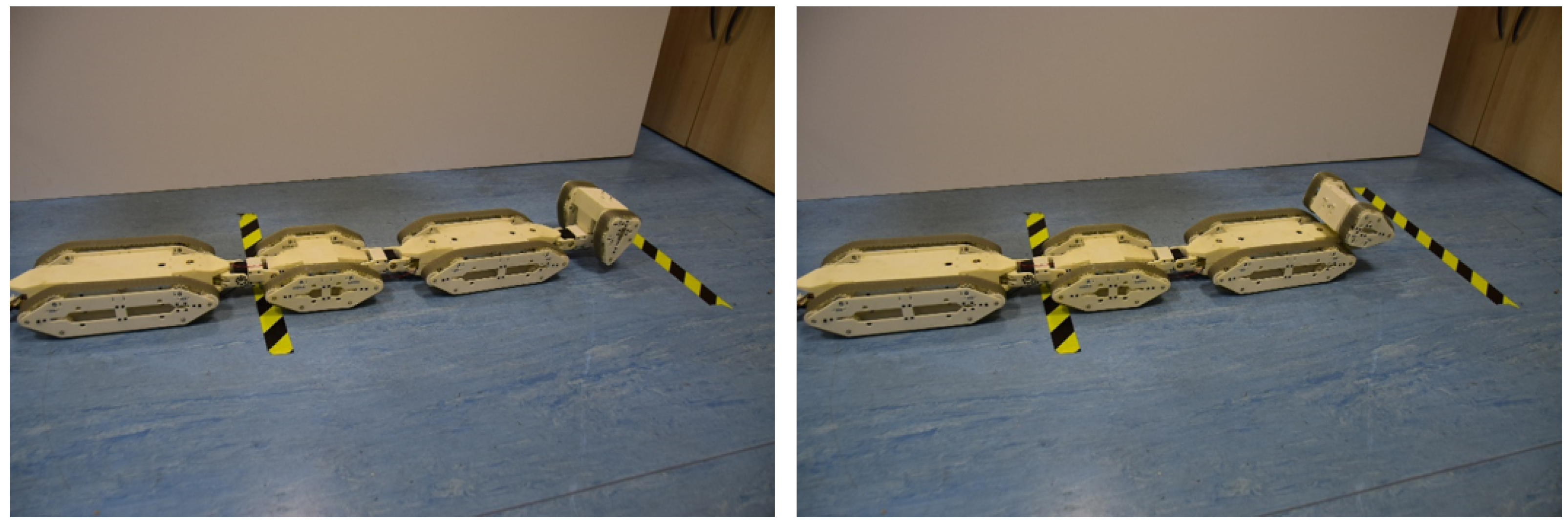
3.3. The S-Configuration

Despite the fact that each pair of active tracks are driven concurrently by the same motor, the Crawler can still turn on the spot. This represents a useful feature, especially in constrained environments to make little adjustments to the robot heading.
For turning the robots on the spot, the yaw joints rotate the modules in a S-configuration while the Crawler Unit is stationary, as in Figure 11. Then, the motors spin the tracks in opposite directions. Given the track linear velocity v, the angular velocity ω of the central module is given by
ω = v sin q l 1 + l 2 cos q
Version one of the Crawler achieved an estimated angular velocity ω = 0.08 [rad/s] and rotated by 1.57 [rad] in t = 20 s when the yaw joints were rotated by 0.87 [rad]. The same experiments were repeated with version two of the Crawler Unit, as shown by the sequences in Figure 12. Unsurprisingly, this new version exhibited a slight difference with regards to the previous result due to the design changes. From data analysis, the active tracks reached an average linear velocity v = 0.03 [m/s] with standard deviation σ = 0.003 [m/s]. Version two achieved an angular velocity ω = 0.07 [rad/s] and rotated by 1.57 [rad] in t = 22 s when the yaw joints were rotated by 0.7 [rad]. Theoretically, it is possible to increase the angular velocity ω shortening l 1 by lifting the central module. Further experiments are required to investigate the most effective configuration.

3.4. Climbing Ramps

Assessing the vertical mobility performance is another crucial aspect in validating the design of the Crawler Unit. In real applications, the robot will operate in complex environments that may include ramps, uneven terrains, stairs, obstacles and curbs. Version one of the Crawler Unit succeeded in climbing and descending ramps, as shown in Figure 13. The robot was tested on slopes up to 20 ° ; beyond this threshold, the friction on the active tracks was not enough to push the Crawler Unit. During the experiments on version one, the docking module was lifted above the ground to help the robot in climbing the initial ramp step. The other pitch joints were disengaged, and the modules adapted to the terrain. The Crawler Unit traveled over the 0.6 m ramp in a time t = 11 s with an estimated average velocity v = 0.05 [m/s].
Version two of the Crawler Unit exhibited similar performance over the same kind of slopes, as shown by the sequence in Figure 14. During these experiments, all the angles of the pitch joints were actively controlled by the operator through the joypad. In this way, the user had an enhanced control over the system. The Crawler Unit traveled 0.8 m and reaches the ramp top in a time t = 15 s, with an estimated average velocity v = 0.05 [m/s].

3.5. Uneven Terrains

The experiments on version one of the prototype were performed on a mock-up scenario with climbs, descents and steps, as shown in Figure 15. Be aware that, in this experimental scenario, version one of the Crawler Unit faced only descending steps and ascending slopes. The pitch joints in this version are not able to lift the modules. Therefore, all the pitch joints were disengaged with the exception of those connecting the front module to the docking module. The back, central and front modules adapted to the terrain, while the docking module weight slightly increased the friction force of the front module. Combining the forward and turning motions, and rotating the modules allowed the operator to recover the Crawler Unit from stuck conditions. As shown in the sequence of Figure 15, version one of the Crawler Unit successfully traversed the 2 m long terrain in a time t = 30 s. Even if the passivity of pitch joints was very useful in descending transitions of terrain, it reduced the overall maneuverability.
This limitation represented one of the reasons why version two of the Crawler Unit has been developed. As already discussed, the new version equips pitch joints with transmissions that increase the output torques and an enhanced joypad, which provides the operator with the ability to actively control the vertical motion of the Crawler Unit modules. The experiments over the uneven terrain were repeated using the newer version. As displayed in Figure 16, version two traversed a scenario even more complex. Here, the Crawler Unit started with the front and docking modules on a platform placed 0.10 m above the central and back modules. Therefore, these last two segments had to climb a step, which was comparable with the height of tracks. Referring to Figure 16, the Crawler Unit successfully overcame that transition height by moving the modules vertically and traversed the 1.5 m long terrain in a time t = 30 s. Such results were encouraging and suggested that version two of the Crawler Unit produced better performance over uneven terrains.
Another possible challenge the Crawler Unit may deal with is the crossing of ditches. Both the versions of the robot were tested in this kind of scenario. As shown in Figure 17, version one succeeded in traversing a gap of length d = 0.25 m. During this experiment, all the pitch joints were active and maintained zero pitch angles between modules. Beyond the threshold d = 0.25 m, the modules got stuck in the ditch due to undesired deflections of pitch joints.
The new Crawler Unit exhibited better performance than the previous version, as shown in Figure 18. As a matter of fact, version two successfully traversed larger gaps, whose length is up to d = 0.4 m. During these tests, the operator drove the robot, choosing how to move the active joints in order to overcome the ditch and reach the top. Here, the threshold d = 0.4 m was not due to the weakness of the pitch joints, but it was determined by the low friction with the ground. In particular, the Crawler became stuck when one of the active modules was not in contact with the ground. In this case, the other active module started to slip on the ground without producing any motion.

3.6. Lifting Modules

As already mentioned, the pitch joints of the Crawler Unit version one do not produce torques high enough to lift the modules. However, version one succeeded in lifting up the docking module and, thanks to the kinematics adopted, this module could flip by 170 ° pointing back toward the tail, as shown in Figure 19. Considering that the final version of the docking module will equip cameras, flipping back this module will allow the operator to see the Crawler Unit tail helping the user in driving the robot backward when it is not in the line of sight.
The performance obtained by version one is promising, but not sufficient. The high reduction ratio of the new transmission reduces the limit angle of each pitch joint. As a result, the docking module in the newer version could rotate at most by 160 ° , as shown in Figure 20. Anyway, the benefits introduced by the new transmissions significantly outweigh the flaws. Referring to Figure 21, the Crawler Unit could push the modules on the ground and lift the others. Such ability confers to the robot more freedom in negotiating complex terrains and, in the future, also the chance of producing snake and caterpillar gaits.

4. Conclusions

In this contribution, the design of a novel modular self-reconfigurable Hybrid Platform for inspection is proposed, which exploits self-reconfigurability and modularity for adapting to many inspection missions. The Hybrid Platform consists of two Crawler Units and a mobile Main Base. These systems perform inspections independently or in collaboration. Through autonomous docking interfaces, the Crawler Units can reconfigure into a snake robot or they can connect to the Main Base, turning the Hybrid Platform into a dual arm system. The focus, here, is on the design and the performance evaluation of the Crawler Units. Each Crawler Unit consists of four modules connected by active joints, sorted in three kinematic chains. For locomotion, the robot adopts a combination of active and passive tracks. Each pair of active tracks is concurrently driven by a single motor. Both versions of the Crawler Unit were tested to compare the maneuverability over various terrains. The good, but yet unsatisfactory experimental results achieved by version one motivated the development of version two. Some design flaws in the first prototype prevented such versions from vertically moving the modules. Version two addressed those defects and succeeded in lifting the modules, overcoming obstacles, larger ditches and steps. Future works will involve the integration of sensors and controllers on the system. A wise choice of navigation and localization sensors, together with the definition of the robot dynamic model, will allow the development of advanced control algorithms. Further experiments will evaluate the performance of the Crawler Unit when it reconfigures into the snake robot and the robotic arm. Finally, the mechatronic design of the mobile Main Base will be defined and the Hybrid Platform general performance will be tested.

Author Contributions

Project coordination, mechanical design and software development, S.L.; supervisor, C.C.; this project was conducted in the Advanced Robotics line of IIT led by D.G.C. All authors have read and agreed to the published version of the manuscript.

Funding

This research received no external funding.

Institutional Review Board Statement

Not applicable.

Informed Consent Statement

Not applicable.

Data Availability Statement

Data is contained within the article.

Acknowledgments

Technical support, Roberto Gagliardi.

Conflicts of Interest

The authors declare no conflict of interest. The investors had no role in the design of the study, in the collection, analyses, or interpretation of data, in the writing of the manuscript, or in the decision to publish the results.

Abbreviations

DoFsDegrees Of Freedom
CoMCenter of Mass

References

  1. Maurtua, I.; Susperregi, L.; Fernández, A.; Tubío, C.; Perez, C.; Rodríguez, J.; Felsch, T.; Ghrissi, M. MAINBOT—Mobile Robots for Inspection and Maintenance in Extensive Industrial Plants. Energy Procedia 2014, 49, 1810–1819. [Google Scholar] [CrossRef] [Green Version]
  2. Soldan, S.; Welle, J.; Barz, T.; Kroll, A.; Schulz, D. Towards Autonomous Robotic Systems for Remote Gas Leak Detection and Localization in Industrial Environments. In Field and Service Robotics; Yoshida, K., Tadokoro, S., Eds.; Springer Tracts in Advanced Robotics; Springer: Berlin/Heidelberg, Germany, 2014; pp. 233–247. ISBN 978-3-642-40685-0. [Google Scholar] [CrossRef]
  3. Merriaux, P.; Rossi, R.; Boutteau, R.; Vauchey, V.; Qin, L.; Chanuc, P.; Rigaud, F.; Roger, F.; Decoux, B.; Savatier, X. The vikings autonomous inspection robot: Competing in the argos challenge. IEEE Robot. Autom. Mag. 2018, 26, 21–34. [Google Scholar] [CrossRef] [Green Version]
  4. Nagatani, K.; Endo, D.; Watanabe, A.; Koyanagi, E. Design and development of explosion-proof tracked vehicle for inspection of offshore oil plant. In Field and Service Robotics; Springer: Berlin/Heidelberg, Germany, 2018; pp. 531–544. [Google Scholar]
  5. Zwicker, E.; Zesch, W.; Moser, R. A modular inspection robot platform for power plant applicationst. In Proceedings of the 2010 1st International Conference on Applied Robotics for the Power Industry, Montreal, QC, Canada, 5–7 October 2010; pp. 1–6. [Google Scholar] [CrossRef]
  6. Caprari, G.; Breitenmoser, A.; Fischer, W.; Hürzeler, C.; Tâche, F.; Siegwart, R.; Nguyen, O.; Moser, R.; Schoeneich, P.; Mondada, F. Highly compact robots for inspection of power plants. J. Field Robot. 2012, 29, 47–68. [Google Scholar] [CrossRef] [Green Version]
  7. Pistone, A.; Canali, C.; Gloriani, C.; Leggieri, S.; Guardiani, P.; Caldwell, D.G. Reconfigurable inspection robot for industrial applications. Procedia Manuf. 2019, 38, 597–604. [Google Scholar] [CrossRef]
  8. Pignone, E.; Pistone, A.; Canali, C.; D’Agostino, F.; Martorana, G. Design and Validation of a Novel Turbogenerator’s Robotized Inspection System. In Turbo Expo: Power for Land, Sea, and Air; American Society of Mechanical Engineers: New York, NY, USA, 2021; Volume 84966, p. V004T05A010. [Google Scholar]
  9. Canali, C.; Pistone, A.; Ludovico, D.; Guardiani, P.; Gagliardi, R.; De Mari Casareto Dal Verme, L.; Sofia, G.; Caldwell, D.G. Design of a Novel Long-Reach Cable-Driven Hyper-Redundant Snake-like Manipulator for Inspection and Maintenance. Appl. Sci. 2022, 12, 3348. [Google Scholar] [CrossRef]
  10. Tur, J.M.M.; Garthwaite, W. Robotic devices for water main in-pipe inspection: A survey. J. Field Robot. 2010, 4, 491–508. [Google Scholar]
  11. Mills, G.H.; Jackson, A.E.; Richardson, R.C. Advances in the inspection of unpiggable pipelines. Robotics 2017, 6, 36. [Google Scholar] [CrossRef] [Green Version]
  12. Hirose, S. Snake-like Locomotors and Manipulators: Biologically Inspired Robots; Oxford University Press: Oxford, UK, 1993. [Google Scholar]
  13. Schempf, H.; Mutschler, E.; Gavaert, A.; Skoptsov, G.; Crowley, W. Visual and nondestructive evaluation inspection of live gas mains using the Explorer™ family of pipe robots. J. Field Robot. 2010, 27, 217–249. [Google Scholar] [CrossRef] [Green Version]
  14. Fjerdingen, S.A.; Liljebäck, P.; Transeth, A.A. A snake-like robot for internal inspection of complex pipe structures (PIKo). In Proceedings of the 2009 IEEE/RSJ International Conference on Intelligent Robots and Systems, St. Louis, MO, USA, 10–15 October 2009; pp. 5665–5671. [Google Scholar]
  15. Fischer, W.; Tâche, F.; Siegwart, R. Inspection system for very thin and fragile surfaces, based on a pair of wall climbing robots with magnetic wheels. In Proceedings of the 2007 IEEE/RSJ International Conference on Intelligent Robots and Systems, San Diego, CA, USA, 29 October–2 November 2007; pp. 1216–1221. [Google Scholar]
  16. Couceiro, M.S.; Portugal, D.; Rocha, R.P.; Ferreira, N.M.F. Marsupial teams of robots: Deployment of miniature robots for swarm exploration under communication constraints. Robotica 2014, 32, 1017–1038. [Google Scholar] [CrossRef] [Green Version]
  17. Zhao, P.; Cao, Z.; Xu, L.; Zhou, C.; Xu, D. The design of a mother robot for marsupial robotic system. In Proceedings of the 2014 IEEE International Conference on Mechatronics and Automation, Tianjin, China, 3–6 August 2014; pp. 675–679. [Google Scholar]
  18. Leggieri, S.; Canali, C.; Cannella, F.; Caldwell, D.G. Novel Modular Self-Reconfigurable Robot for Pipe and Plant Inspection. In Proceedings of the ICAS 2020: The Sixteenth International Conference on Autonomic and Autonomous Systems, Lisbon, Portugal, 27 September–1 October 2020; pp. 36–40. [Google Scholar]
  19. Leggieri, S.; Canali, C.; Cannella, F.; Caldwell, D.G. Self-reconfigurable hybrid robot for inspection. In Proceedings of the 2020 I-RIM Conference, Virtual, 10–13 December 2020; pp. 268–269. [Google Scholar] [CrossRef]
  20. Leggieri, S.; Canali, C.; Gagliardi, R.; Cannella, F.; Caldwell, D.G. Hybrid Self-Reconfigurable Platform for Inspection: The Crawler Unit. In Proceedings of the 2021 I-RIM Conference, Roma, Italy, 8–10 October 2021; pp. 53–55. [Google Scholar] [CrossRef]
  21. Leggieri, S.; Canali, C.; Cannella, F.; Lee, J.; Caldwell, D.G. Preliminary Study on the Crawler Unit of a Novel Self-Reconfigurable Hybrid Platform for Inspection. In Proceedings of the 20th International Conference on Advanced Robotics, ICAR 2021, Ljubljana, Slovenia, 6–10 December 2021; pp. 77–82. [Google Scholar]
  22. Siciliano, B.; Khatib, O. Springer Handbook of Robotics; Springer: Berlin/Heidelberg, Germany, 2016; ISBN 978-3-540-23957-4. [Google Scholar]
  23. Sciavicco, L.; Siciliano, B. Modelling and Control of Robot Manipulators; Springer Science & Business Media: Berlin/Heidelberg, Germany, 2001. [Google Scholar]
  24. Real Time Engineers Ltd. FreeRTOS. Available online: https://www.freertos.org/ (accessed on 20 May 2022).
Figure 1. Representation of the Hybrid Platform robot executing different tasks. In (a), the Crawler Units are deployed/recovered near/from an inspection site; in (b), the Main Base operates the Crawler Units as robotic arms to inspect a target on sidewalls; in (c), the Crawler Units perform inspection in narrow areas, moving around some obstacles; in (d), the Crawler Units adopt the snake configuration to reach a manometer placed above the ground; in (e), the Crawler Units adopt the snake configuration to inspect the internal surface of a tank.
Applsci 12 05579 g001
Figure 2. CAD drawing of the Crawler Unit version two. Each module is 0.11 m high and 0.22 m wide. In total, the robot is 1.54 m long.
Applsci 12 05579 g002
Figure 3. Snapshots of the Crawler Unit prototypes. On top, version one of the Crawler. Due to the conservative design, each module has an average weight of 2 Kg. On bottom, version two of the Crawler. The new prototype includes thinner parts and design improvements. Each module has an average weight of 1.7 Kg.
Applsci 12 05579 g003
Figure 4. Schematic representation of the Crawler Unit kinematics. The inertial frame is denoted by W , and the local frame B is attached to the central module center of mass (CoM). The i 1 -th local frame is attached to all the i-th joint, and frames E f and E r identify the Crawler Unit extremes. The x, y and z axis of each frame are denoted by the red, green and blue colors, respectively. Orange arrows represent the joint degree of freedom (DoF).
Applsci 12 05579 g004
Figure 5. Detailed view of one kinematic chain that connects the Crawler Unit modules. From left to right, the yaw and the pitch joints are assembled into a Cardan joint, which is connected to the second pitch joint. In all joints, the servomotors are equipped with dual stage transmissions.
Applsci 12 05579 g005
Figure 6. The representation of the Crawler Unit electronics and control architecture. The robot is powered through an umbilical cable connected to the power supply. The code is uploaded into the microcontroller, which manages the joypad inputs.
Applsci 12 05579 g006
Figure 7. Forward motion sequence. The Crawler Unit version one travels 1 m forward from the starting position, on the left, toward the finish line, on the right. The robot achieves an average speed of v = 0.1 [m/s].
Applsci 12 05579 g007
Figure 8. Forward motion sequence. The Crawler Unit version two travels 1 m forward from the starting position, on the left, toward the finish line, on the right. The robot achieves an average speed of v = 0.1 [m/s].
Applsci 12 05579 g008
Figure 9. Turning motion sequence adopting the C-configuration. The Crawler Unit version one rotates by 1.57 [rad] in t = 15 s, reaching an angular velocity ω = 0.1 [rad/s] with a curvature radius ρ = 0.45 m.
Applsci 12 05579 g009
Figure 10. Turning motion sequence adopting the C-configuration. The Crawler Unit version two rotates by 1.57 [rad] in t = 17 s, achieving an angular velocity ω = 0.09 [rad/s] with curvature radius ρ = 0.6 m.
Applsci 12 05579 g010
Figure 11. Turning motion sequence adopting the S-configuration. The Crawler Unit version one rotates on the spot by 1.57 [rad] in t = 20 s, achieving an angular velocity ω = 0.08 [rad/s].
Applsci 12 05579 g011
Figure 12. Turning motion sequence adopting the S-configuration. The Crawler Unit version two rotates on the spot by 1.57 [rad] in t = 22 s, reaching an angular velocity ω = 0.07 [rad/s].
Applsci 12 05579 g012
Figure 13. Climbing ramp sequence. The Crawler Unit version one climbs a 0.6 m ramp with a slope up to 20 ° in t = 11 s.
Applsci 12 05579 g013
Figure 14. Climbing ramp sequence. The Crawler Unit version two climbs a 0.8 m ramp with a slope up to 20 ° in t = 15 s.
Applsci 12 05579 g014
Figure 15. Uneven terrain sequence. The Crawler Unit version one traverses a 2 m long uneven terrain which includes ascending ramps and descending steps.
Applsci 12 05579 g015
Figure 16. Uneven terrain sequence. The Crawler Unit version two traverses a 1.5 m long uneven terrain, which includes ascending and descending steps and ascending ramp.
Applsci 12 05579 g016
Figure 17. Overcoming ditch sequence. The Crawler Unit version one traverses a plain terrain with 0.25 m long ditch.
Applsci 12 05579 g017
Figure 18. Overcoming ditch sequence. The Crawler Unit version two traverses an uneven terrain with 0.4 m long ditch.
Applsci 12 05579 g018
Figure 19. Lifting modules sequence. The Crawler Unit version one flips the docking module backward. The two pitch joints in the kinematic chain allows one to rotate the docking module by 170 ° .
Applsci 12 05579 g019
Figure 20. Lifting modules sequence. The Crawler Unit version one flips the docking module backward. The new transmission on each pitch joint reduces the limit angle, and the docking module can rotate by 160 ° .
Applsci 12 05579 g020
Figure 21. Lifting modules snapshots. On the left, the docking and the central modules push on the terrain and the front module raises above the ground. On the right, the back and the front modules push on the terrain, raising the central module.
Applsci 12 05579 g021
Table 1. Parameters of the Crawler Unit, version one.
Crawler Unit Version One
Back ModuleCentral Module
Applsci 12 05579 i001Length = 0.4 m; Applsci 12 05579 i002Length = 0.44 m;
Height = 0.11 m;Height = 0.11 m;
Width = 0.22 m;Width = 0.22 m;
Mass = 2.3 Kg.Mass = 2 Kg.
Front ModuleDocking Module
Applsci 12 05579 i003Length = 0.4 m; Applsci 12 05579 i004Length = 0.22 m;
Height = 0.11 m;Height = 0.11 m;
Width = 0.22 m;Width = 0.22 m;
Mass = 2.5 Kg.Mass = 1.3 Kg.
TOTAL MASS = 8.1 Kg;TOTAL LENGTH = 1.46 m.
Table 2. Parameters of the Crawler Unit version two.
Crawler Unit Version Two
Back ModuleCentral Module
Applsci 12 05579 i005Length = 0.4 m; Applsci 12 05579 i006Length = 0.49 m;
Height = 0.11 m;Height = 0.11 m;
Width = 0.22 m;Width = 0.22 m;
Mass = 1.8 Kg.Mass = 2.1 Kg.
Front ModuleDocking Module
Applsci 12 05579 i007Length = 0.4 m; Applsci 12 05579 i008Length = 0.25 m;
Height = 0.11 m;Height = 0.11 m;
Width = 0.22 m;Width = 0.22 m;
Mass = 2 Kg.Mass = 1.3 Kg.
TOTAL MASS = 7.2 Kg;TOTAL LENGTH = 1.54 m.
Table 3. The Denavit–Hartenberg parameters of the Crawler Unit kinematics.
Reference Frame a i α i d i θ i
B 0 f l c / 2 π / 2 00
0 f 1 f l l 00 q 1
1 f 2 f l ρ π / 2 0 q 2
2 f 3 f l f 00 q 3
3 f 4 f l ρ π / 2 0 q 4
4 f 5 f l l 00 q 5
5 f E f l d π / 2 0 q 6
B 0 r l c / 2 π / 2 0 π
0 r 1 r l l 00 q 7
1 r 2 r l ρ π / 2 0 q 8
2 r E r l r 00 q 9
Table 4. The Crawler Unit technical specifications.
Herkulex ServomotorModel: DRS-0602
Total weight: 145 g
Total Stall Torque: 7.6 Nm
Reduction Ratio: 202:1
Maxon MotorModel: DCX12L
Total weight: 36.6 g
Total Stall Torque: 0.99 Nm
Reduction Ratio: 83:1
Arduino BoardModel: Mega 2560
Microcontroller: ATmega 2560
Clock Frequency: 16 MHz
L298N Motor DriverDriver: L298N Dual H Bridge
Motor Channels: 2
Driver Voltage: 5–35 V
Publisher’s Note: MDPI stays neutral with regard to jurisdictional claims in published maps and institutional affiliations.

