
Multi-Timescale Control of Variable-Speed Wind Turbine for Inertia Provision


Abstract
:1. Introduction
- (1).
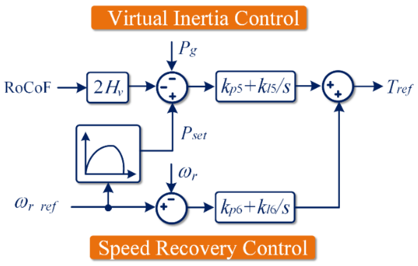
- Revealing the coupling effect between virtual inertia control and speed recovery control of the wind energy conversion system with an investigation of the corresponding impact on the performance of RoCoF suppression;
- (2).
- Decoupling of rotor speed recovery control and inertia control into different timescales; as a result, the inertia provision and speedy post-event recovery objectives can be simultaneously achieved;
- (3).
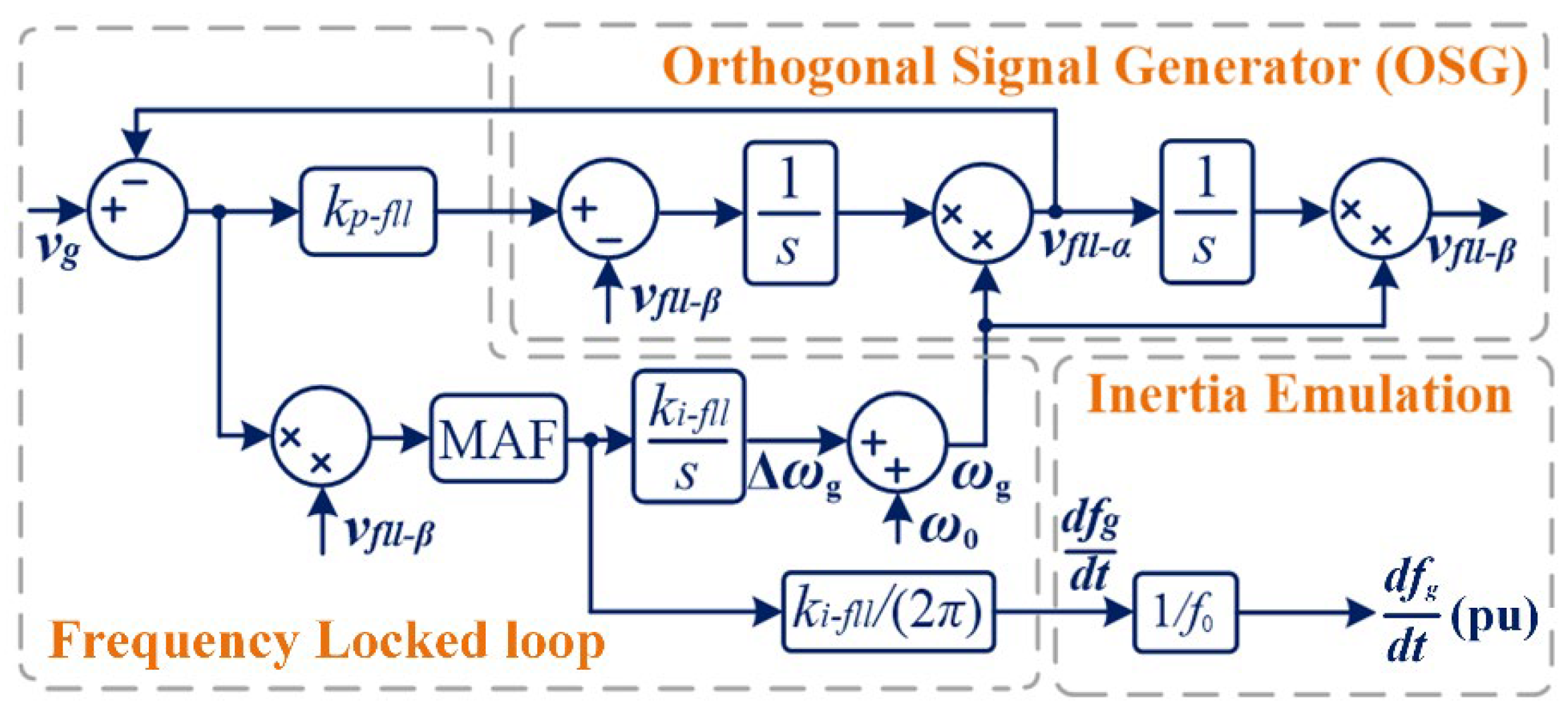
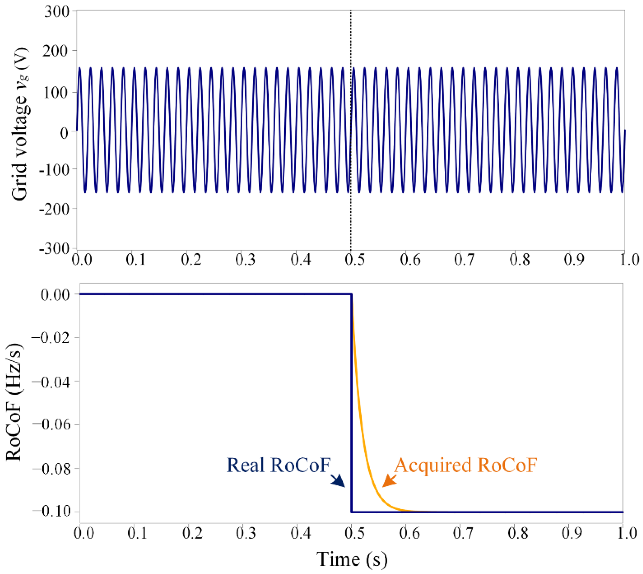
- Designing a noise-free approach to acquire the real-time grid RoCoF, the response time of which is less than 0.1 s;
- (4).
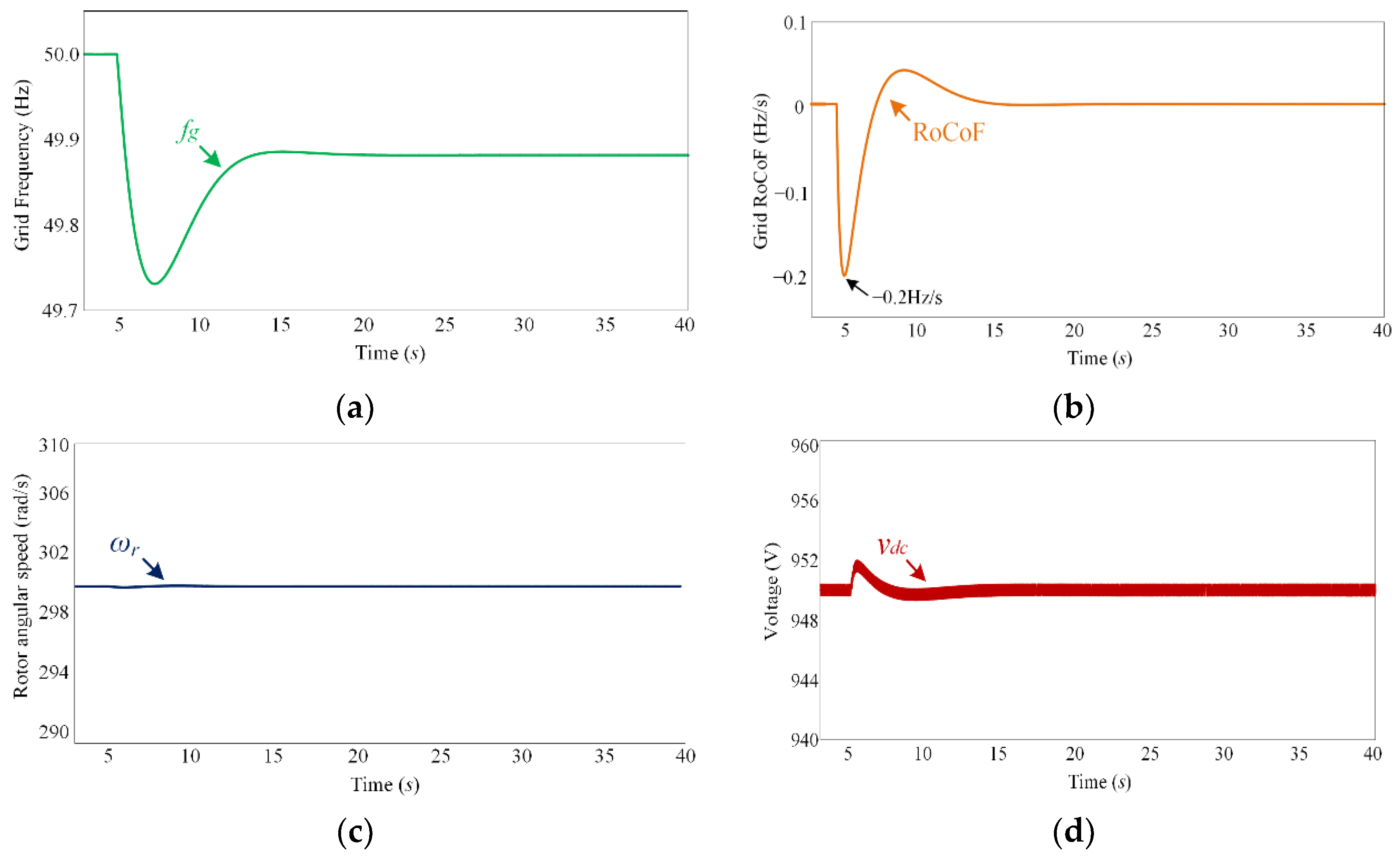
- Conducting simulations to verify the theoretical analysis and control performance. With the wind turbine virtual inertia being 5 s, the maximum RoCoF is successfully reduced by around 23%.
2. Principle of Inertia Emulation
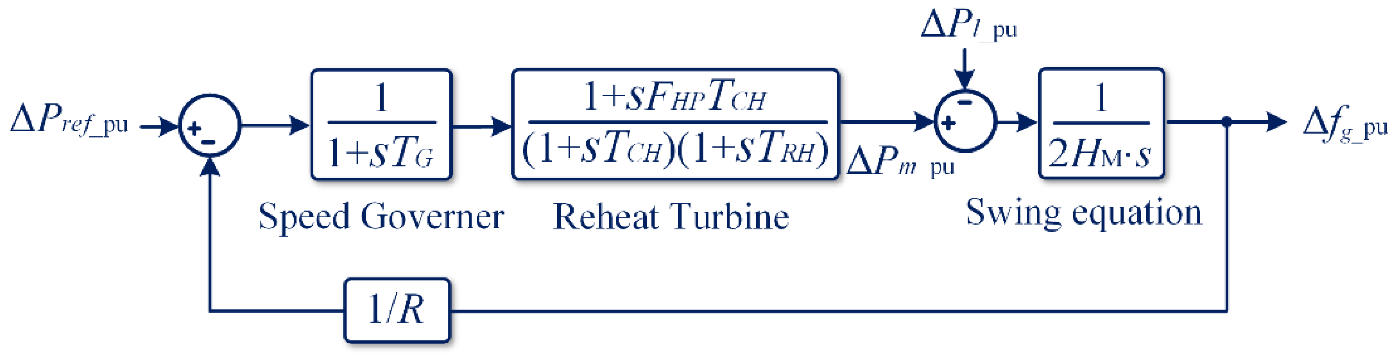
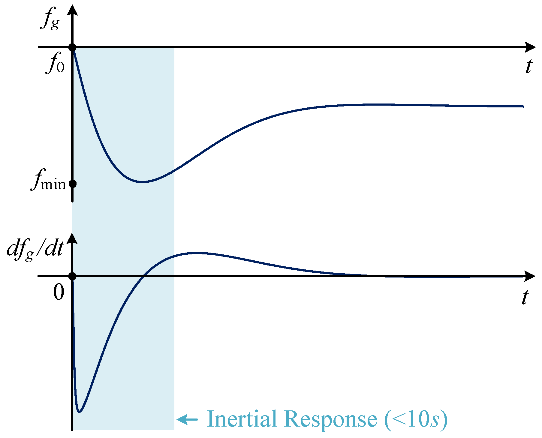
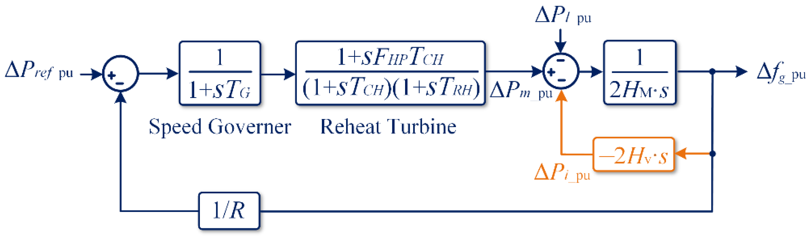
2.1. Power System Frequency Response
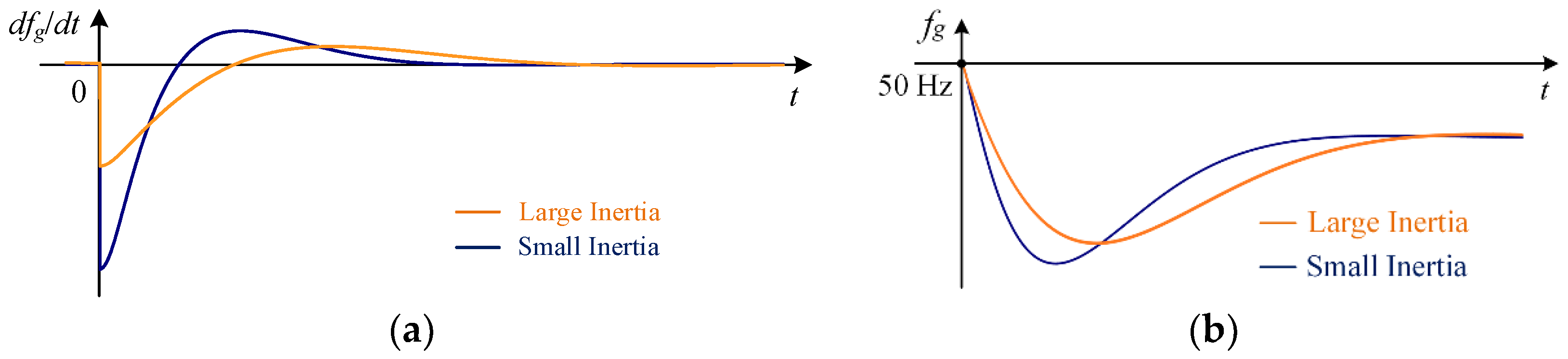
2.2. Inertia Provision Principle
3. Inertia Provision Control Strategy
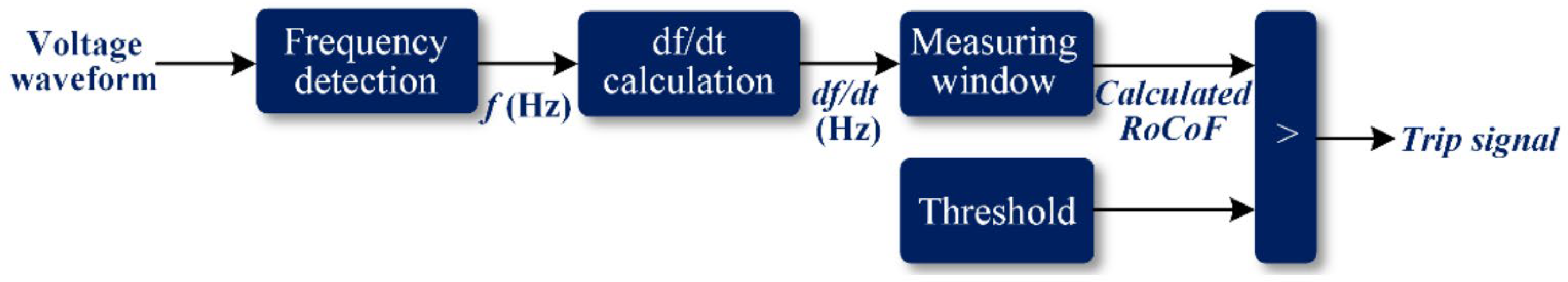
3.1. Acquistion of RoCoF
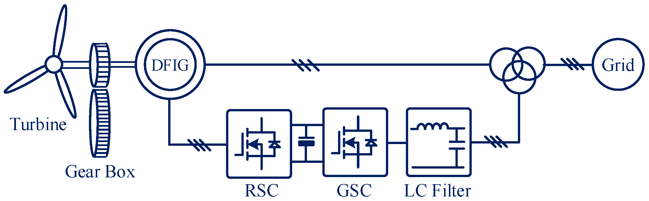
3.2. DFIG System Control
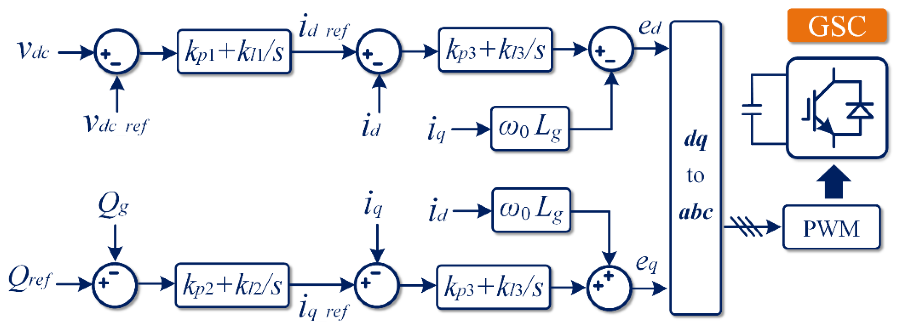
3.2.1. GSC Control Scheme
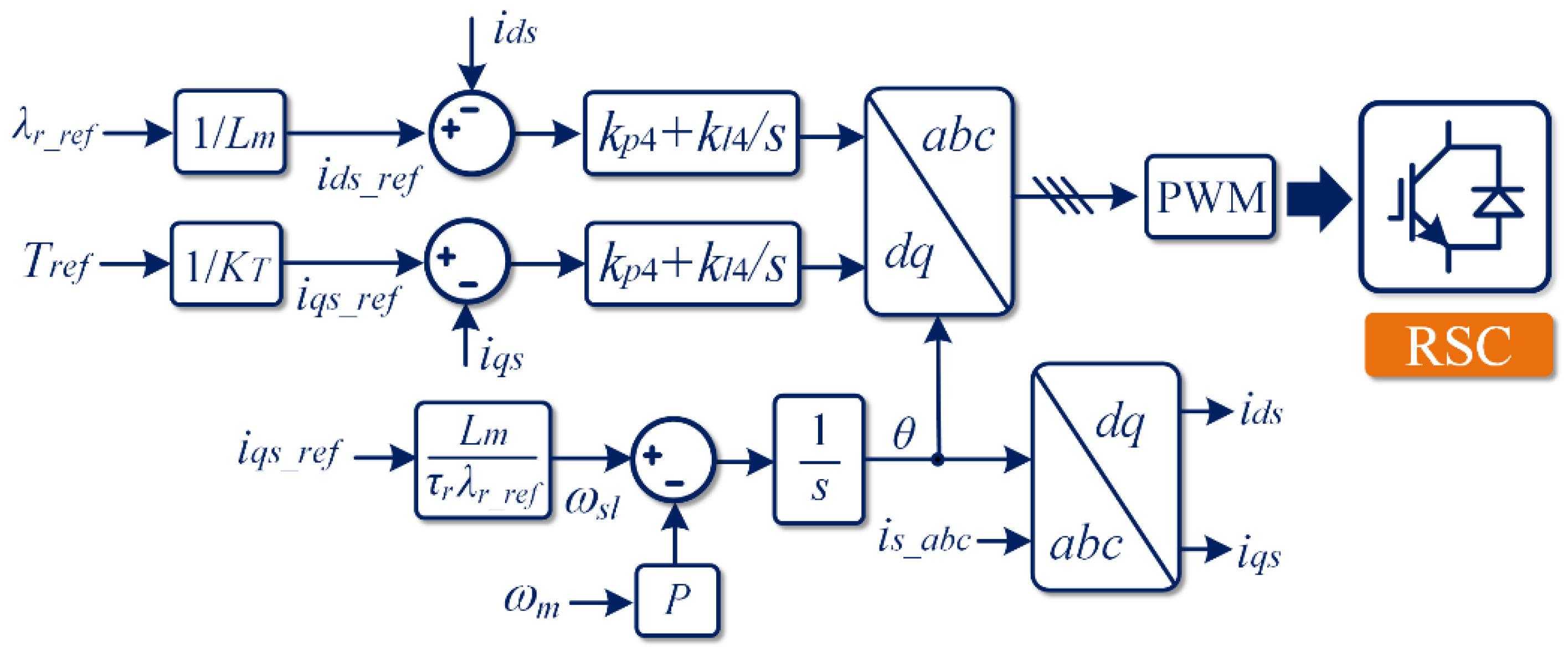
3.2.2. RSC Control Scheme
4. Simulation Results
5. Conclusions
Author Contributions
Funding
Institutional Review Board Statement
Informed Consent Statement
Conflicts of Interest
References
- Peng, Q.; Jiang, Q.; Yang, Y.; Liu, T.; Wang, H.; Blaabjerg, F. On the Stability of Power Electronics-Dominated Systems: Challenges and Potential Solutions. IEEE Trans. Ind. Appl. 2019, 55, 7657–7670. [Google Scholar] [CrossRef]
- Fang, J.; Li, H.; Tang, Y.; Blaabjerg, F. On the Inertia of Future More-Electronics Power Systems. IEEE J. Emerg. Sel. Top. Power Electron. 2019, 7, 2130–2146. [Google Scholar] [CrossRef]
- Microgrids, F.C.; Arco, S.D.; Suul, J.A. Equivalence of Virtual Synchronous Machines and Frequency-Droops for Converter-Based MicroGrids. IEEE Trans. Smart Grid 2014, 5, 394–395. [Google Scholar]
- Huang, L.; Xin, H.; Wang, Z. Damping Low-Frequency Oscillations through VSC-HVdc Stations Operated as Virtual Synchronous Machines. IEEE Trans. Power Electron. 2019, 34, 5803–5818. [Google Scholar] [CrossRef]
- Australian Energy Market Commission (AEMC), Mechanisms to Enhance Resilience in the Power System—Review of the South Australia Black System Event. Tech. Rep. 2019. Available online: https://www.aemc.gov.au/sites/default/files/documents/aemc_-_sa_black_system_review_-_final_report.pdf (accessed on 11 February 2022).
- Zhong, Q.C.; Weiss, G. Synchronverters: Inverters that mimic synchronous generators. IEEE Trans. Ind. Electron. 2011, 58, 1259–1267. [Google Scholar] [CrossRef]
- Khajehoddin, S.A.; Karimi-Ghartemani, M.; Ebrahimi, M. Grid-supporting inverters with improved dynamics. IEEE Trans. Ind. Electron. 2019, 66, 3655–3667. [Google Scholar] [CrossRef]
- Fang, J.; Li, H.; Tang, Y.; Blaabjerg, F. Distributed Power System Virtual Inertia Implemented by Grid-Connected Power Converters. IEEE Trans. Power Electron. 2018, 33, 8488–8499. [Google Scholar] [CrossRef] [Green Version]
- Blaabjerg, F.; Teodorescu, R.; Liserre, M.; Timbus, A.V. Overview of control and grid synchronization for distributed power generation systems. IEEE Trans. Ind. Electron. 2006, 53, 1398–1409. [Google Scholar] [CrossRef] [Green Version]
- Qi, Y.; Deng, H.; Liu, X.; Tang, Y. Synthetic Inertia Control of Grid-Connected Inverter Considering the Synchronization Dynamics. IEEE Trans. Power Electron. 2022, 37, 1411–1421. [Google Scholar] [CrossRef]
- Zhang, R.; Fang, J.; Tang, Y. Inertia Emulation through Supercapacitor Energy Storage Systems. In Proceedings of the 2019 10th International Conference on Power Electronics and ECCE Asia (ICPE 2019-ECCE Asia), Busan, Korea, 27–30 May 2019; Volume 3, pp. 1365–1370. [Google Scholar] [CrossRef]
- Yan, X.; Sun, X. Inertia and droop frequency control strategy of doubly-fed induction generator based on rotor kinetic energy and supercapacitor. Energies 2020, 13, 3697. [Google Scholar] [CrossRef]
- Chen, T.; Guo, J.; Chaudhuri, B.; Hui, S.Y. Virtual Inertia from Smart Loads. IEEE Trans. Smart Grid 2020, 11, 4311–4320. [Google Scholar] [CrossRef]
- Mutoh, N.; Ohno, M.; Inoue, T. A method for MPPT control while searching for parameters corresponding to weather conditions for PV generation systems. IECON Proc. Ind. Electron. Conf. 2004, 3, 3094–3099. [Google Scholar] [CrossRef]
- Wang, X.; Yue, M.; Muljadi, E. PV generation enhancement with a virtual inertia emulator to provide inertial response to the grid. In Proceedings of the 2014 IEEE Energy Conversion Congress and Exposition (ECCE), Pittsburgh, PA, USA, 14–18 September 2014; pp. 17–23. [Google Scholar] [CrossRef]
- Chen, Z.; Lasseter, R.H.; Jahns, T.M. Active power reserve control for grid-forming PV sources in microgrids using model-based maximum power point estimation. In Proceedings of the 2019 IEEE Energy Conversion Congress and Exposition (ECCE), Baltimore, MD, USA, 29 September–3 October 2019; pp. 41–48. [Google Scholar] [CrossRef]
- Zhong, C.; Zhou, Y.; Yan, G. Power reserve control with real-time iterative estimation for PV system participation in frequency regulation. Int. J. Electr. Power Energy Syst. 2021, 124, 106367. [Google Scholar] [CrossRef]
- Zhang, X.; Gao, Q.; Hu, Y.; Zhang, H.; Guo, Z. Active power reserve photovoltaic virtual synchronization control technology. Chin. J. Electr. Eng. 2020, 6, 1–6. [Google Scholar] [CrossRef]
- Peng, Q.; Tang, Z.; Yang, Y.; Liu, T.; Blaabjerg, F. Event-Triggering Virtual Inertia Control of PV Systems with Power Reserve. IEEE Trans. Ind. Appl. 2021, 57, 4059–4070. [Google Scholar] [CrossRef]
- Peng, Q. Coordination of Virtual Inertia Control and Frequency Damping in PV Systems for Optimal Frequency Support. CPSS Trans. Power Electron. Appl. 2020, 5, 305–316. [Google Scholar] [CrossRef]
- Brisebois, J.; Aubut, N. Wind farm inertia emulation to fulfill Hydro-Québec’s specific need. In Proceedings of the 2011 IEEE Power and Energy Society General Meeting, Detroit, MI, USA, 24–28 July 2011; Volume 7, pp. 1–7. [Google Scholar] [CrossRef]
- Holdsworth, L.; Ekanayake, J.B.; Jenkins, N. Power system frequency response from fixed speed and doubly fed induction generator-based wind turbines. Wind Energy 2004, 7, 21–35. [Google Scholar] [CrossRef]
- Ekanayake, J.; Jenkins, N. Comparison of the response of doubly fed and fixed-speed induction generator wind turbines to changes in network frequency. IEEE Trans. Energy Convers. 2004, 19, 800–802. [Google Scholar] [CrossRef]
- Lalor, G.; Mullane, A.; O’Malley, M. Frequency control and wind turbine technologies. IEEE Trans. Power Syst. 2005, 20, 1905–1913. [Google Scholar] [CrossRef]
- Guo, X.; Zhu, D.; Zou, X.; Jiang, B.; Yang, Y.; Kang, Y.; Peng, L. Dynamic Inertia Evaluation for type-3 Wind Turbines Based on Inertia Function. IEEE J. Emerg. Sel. Top. Circuits Syst. 2021, 11, 28–38. [Google Scholar] [CrossRef]
- Van De Vyver, J.; De Kooning, J.D.M.; Meersman, B.; Vandevelde, L.; Vandoorn, T.L. Droop Control as an Alternative Inertial Response Strategy for the Synthetic Inertia on Wind Turbines. IEEE Trans. Power Syst. 2016, 31, 1129–1138. [Google Scholar] [CrossRef]
- Li, Y.; Xu, Z.; Wong, K.P. Advanced Control Strategies of PMSG-Based Wind Turbines for System Inertia Support. IEEE Trans. Power Syst. 2017, 32, 3027–3037. [Google Scholar] [CrossRef]
- Tian, X.; Wang, W.; Chi, Y.; Li, Y.; Liu, C. Virtual inertia optimisation control of DFIG and assessment of equivalent inertia time constant of power grid. IET Renew. Power Gener. 2018, 12, 1733–1740. [Google Scholar] [CrossRef]
- Junyent-Ferré, A.; Pipelzadeh, Y.; Green, T.C. Blending HVDC-Link Energy Storage and Offshore Wind Turbine Inertia for Fast Frequency Response. IEEE Trans. Sustain. Energy 2015, 6, 1059–1066. [Google Scholar] [CrossRef] [Green Version]
- Morren, J.; de Haan, S.W.H.; Kling, W.L.; Ferreira, J.A. Wind turbines emulating inertia and supporting primary frequency control. IEEE Trans. Power Syst. 2006, 21, 433–434. [Google Scholar] [CrossRef]
- Xi, X.; Geng, H.; Yang, G. Small signal stability of weak power system integrated with inertia tuned large scale wind farm. In Proceedings of the 2014 IEEE Innovative Smart Grid Technologies-Asia (ISGT ASIA), Kuala Lumpur, Malaysia, 20–23 May 2014; pp. 514–518. [Google Scholar] [CrossRef]
- Ma, J.; Qiu, Y.; Li, Y.; Zhang, W.; Song, Z.; Thorp, J.S. Research on the impact of DFIG virtual inertia control on power system small-signal stability considering the phase-locked loop. IEEE Trans. Power Syst. 2017, 32, 2094–2105. [Google Scholar] [CrossRef]
- Ten, C.F.; Crossley, P.A. Evaluation of ROCOF relay performances on networks with distributed generation. In Proceedings of the 2008 IET 9th International Conference on Developments in Power System Protection (DPSP 2008), Glasgow, UK, 17–20 March 2008; pp. 522–527. [Google Scholar] [CrossRef]
- DNV GL Energy Advisory (for EirGrid plc), RoCoF Alternative Solutions Technology Assessment: High level assessment of frequency measurement and FFR type technologies and the relation with the present status for the reliable detection of high RoCoF events in a adequate time frame. Tech. Rep., No. 16011111, rev. 005. 2015. Available online: https://www.eirgridgroup.com/site-files/library/EirGrid/RoCoF-Alternative-Solutions-Technology-Assessment-Phase-1-DNV-GL-Report_.pdf (accessed on 11 February 2022).
- Qi, Y.; Yang, T.; Fang, J.; Tang, Y.; Potti, K.R.R.; Rajashekara, K. Grid Inertia Support Enabled by Smart Loads. IEEE Trans. Power Electron. 2021, 36, 947–957. [Google Scholar] [CrossRef]
- Fang, J.; Zhang, R.; Li, H.; Tang, Y. Frequency Derivative-based Inertia Enhancement by Grid-Connected Power Converters with a Frequency-Locked-Loop. IEEE Trans. Smart Grid 2018, 10, 4918–4927. [Google Scholar] [CrossRef]
- Wu, B.; Narimani, M. High-Power Converters and AC Drives; John Wiley & Sons: Hoboken, NJ, USA, 2017. [Google Scholar]


| Parameter | Description | Value |
|---|---|---|
| R | Frequency droop slope (p.u.) | 0.05 |
| TG | Speed governor constant | 0.1 s |
| FHP | Turbine HP constant | 0.3 s |
| TRH | Reheater time constant | 7.0 s |
| TCH | Inlet volume time constant | 0.2 s |
| D | Load-damping coefficient (p.u.) | 1.0 |
| HM | Synchronous machine inertia (p.u.) | 5.0 s |
| Vg | Grid voltage magnitude | 1000 V |
| ω0 | Nominal grid frequency | 100∙π rad/s |
| VAbase | System base power (1 p.u.) | 10 MW |
| Jr | Moment of inertia (turbine rotor) | 75 kg∙m2 |
| Hv | Virtual inertia (p.u.) | 2.0 s |
| ωr_ref | Reference rotor speed | 300 rad/s |
| Pset | Active power set power | 2.5 MW |
| Scenario | Maximum Frequency Error | Maximum RoCoF Error | Maximum Rotor Speed Error | Maximum DC-Link Voltage Error |
|---|---|---|---|---|
| Case 1 (Figure 12) | 0.27 Hz | 0.2 Hz/s | 0.4 rad/s | 1.9 V |
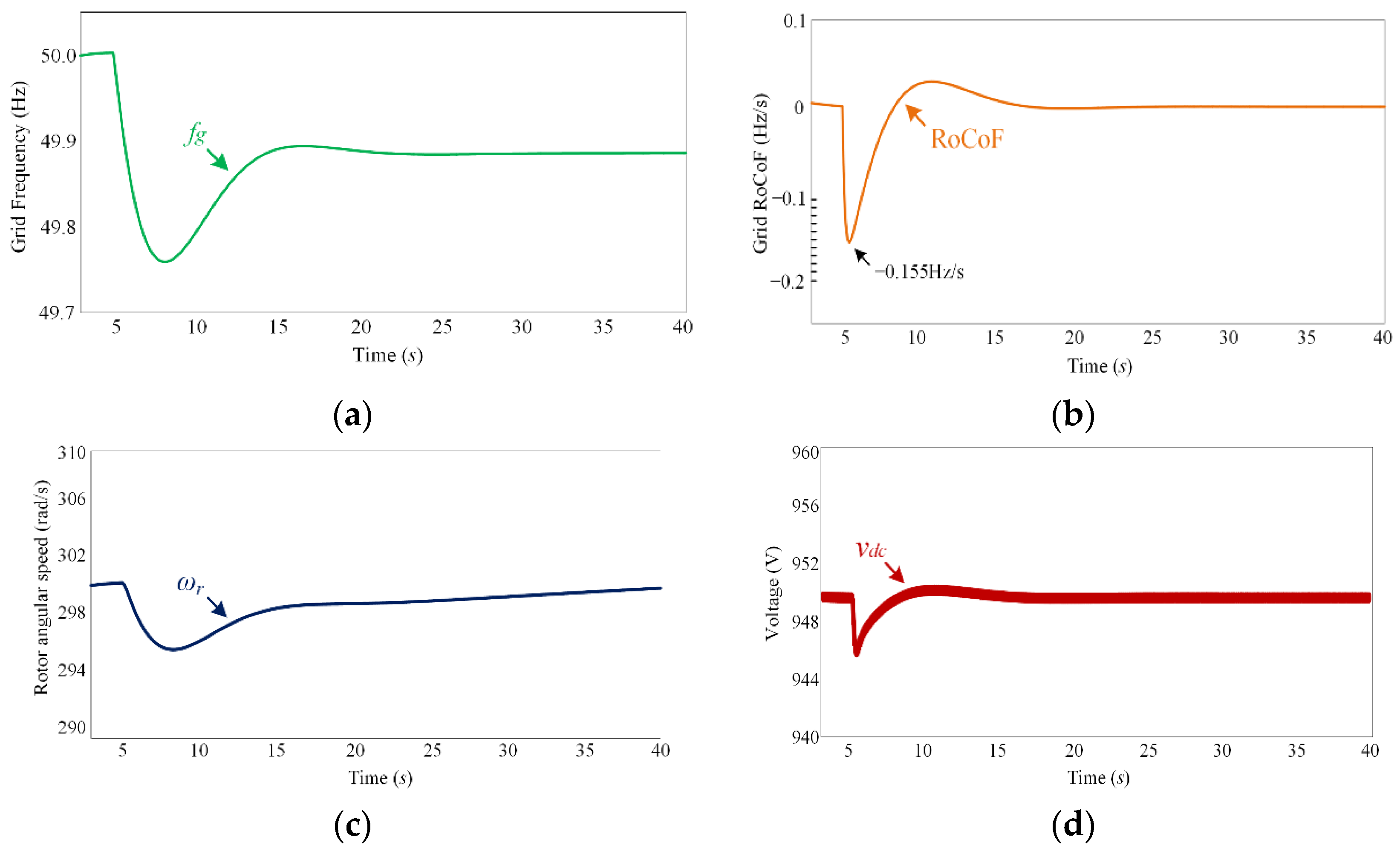
| Case 2 (Figure 13) | 0.24 Hz | 0.155 Hz/s | 4.4 rad/s | 5.3 V |
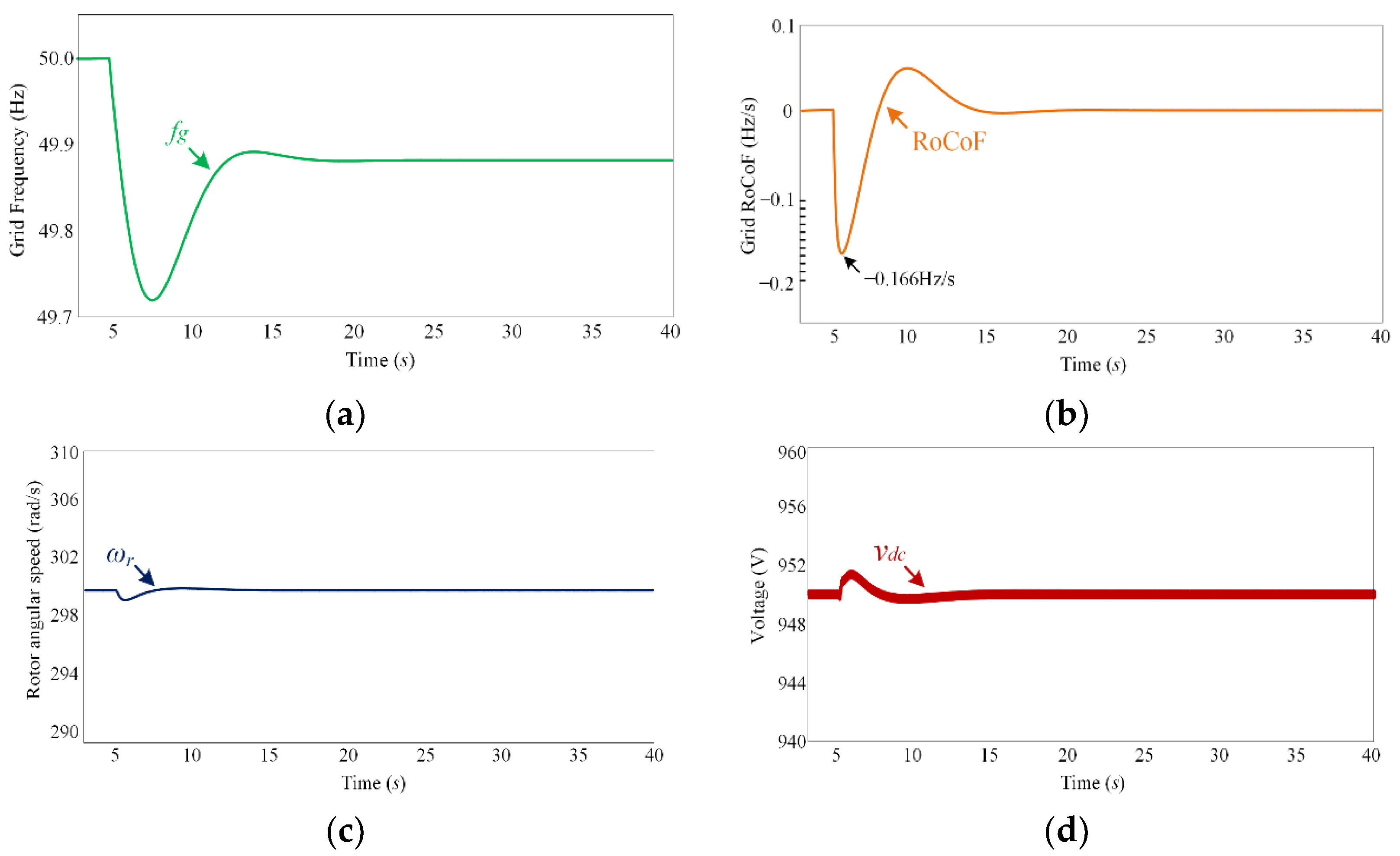
| Case 3 (Figure 14) | 0.27 Hz | 0.166 Hz/s | 0.9 rad/s | 1.7 V |
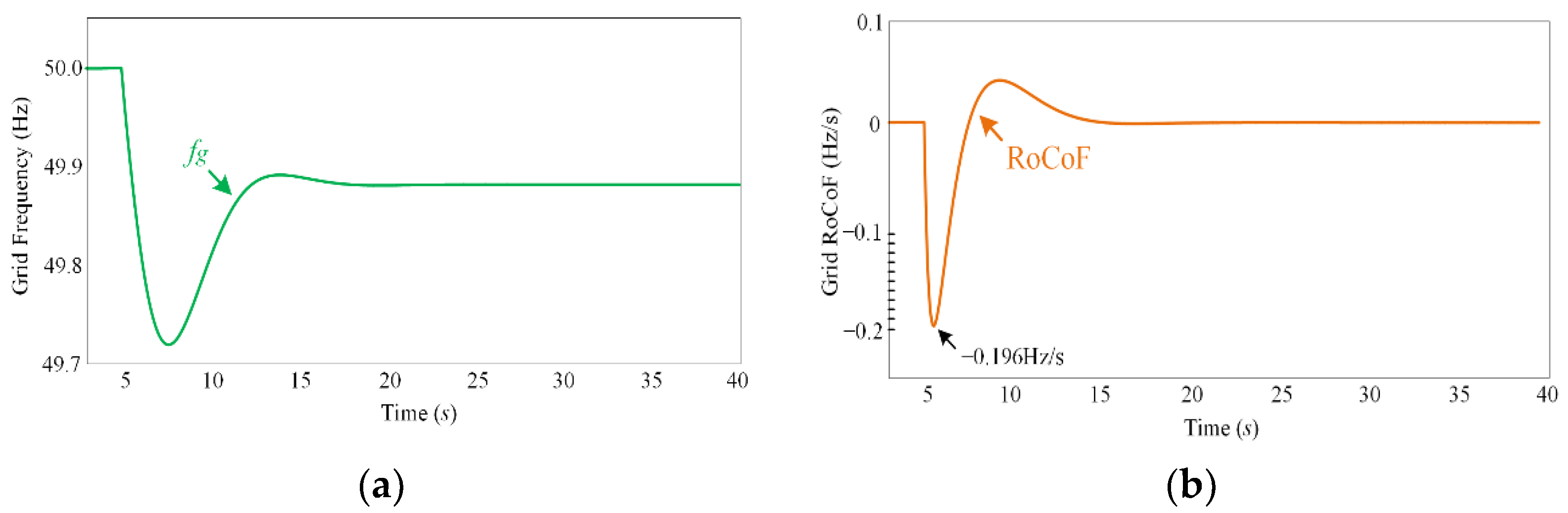
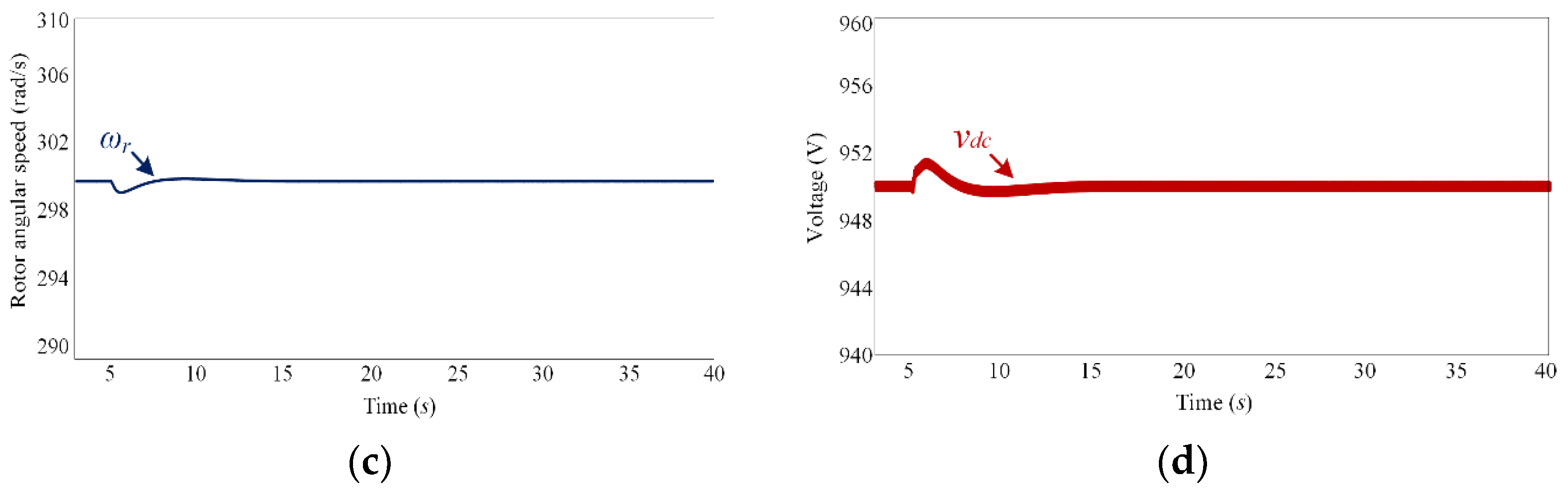
| Case 4 (Figure 15) | 0.27 Hz | 0.2 Hz/s | 0.9 rad/s | 1.7 V |
Publisher’s Note: MDPI stays neutral with regard to jurisdictional claims in published maps and institutional affiliations. |
© 2022 by the authors. Licensee MDPI, Basel, Switzerland. This article is an open access article distributed under the terms and conditions of the Creative Commons Attribution (CC BY) license (https://creativecommons.org/licenses/by/4.0/).
Share and Cite
Xu, Z.; Qi, Y.; Li, W.; Yang, Y. Multi-Timescale Control of Variable-Speed Wind Turbine for Inertia Provision. Appl. Sci. 2022, 12, 3263. https://doi.org/10.3390/app12073263
Xu Z, Qi Y, Li W, Yang Y. Multi-Timescale Control of Variable-Speed Wind Turbine for Inertia Provision. Applied Sciences. 2022; 12(7):3263. https://doi.org/10.3390/app12073263
Chicago/Turabian StyleXu, Zixiao, Yang Qi, Weilin Li, and Yongheng Yang. 2022. "Multi-Timescale Control of Variable-Speed Wind Turbine for Inertia Provision" Applied Sciences 12, no. 7: 3263. https://doi.org/10.3390/app12073263