1. Introduction
This study relates targeted temperature manipulation in Extrusion Additive Manufacturing (EAM) to deposition parameters, external heating and cooling, and the resulting material behavior. We evaluate the potential of heating and cooling methods for EAM processes while creating a basis for further research efforts and in-depth analysis of the correlating mechanical performance. For the manufacturing of large and complex structural parts, the BMW Group has invested in the development of a custom build Freeform Extrusion Additive Manufacturing (FEAM) facility, which is a robot-based large format deposition system. While this technology aims to move from planar slicing to load path-oriented deposition, its extensive sensor equipment and real-time data acquisition make it well suited for planar parameter variations and investigations into technological enhancements. The use of short carbon fiber-filled thermoplastics in pellet form can further improve the mechanical properties of the polymer and drastically increase the throughput of the system compared to filament-based systems [
1,
2].
While industries such as the aerospace, transport, and automotive sector have often used high-volume manufacturing processes, Additive Manufacturing (AM) poses new benefits in terms of individualization, low-volume productions, higher complexities, short lead times, and potential reductions in part costs, especially in prototyping [
3]. Due to the vast variety of AM processes, the selection of suitable processes with their corresponding product chain becomes increasingly important [
3]. With each different AM process posing new challenges for manufacturing parameters and part optimization, the main detriments and control levers have to be identified and investigated accordingly.
The main challenge for most layer-based AM technologies is the directional bias [
2,
4], which is particularly evident in tensile testing [
5]. The material performance in the longitudinal strand direction depends mainly on the properties of the bulk material within the strand. However, the transverse strength in the z-direction depends on the bond formation across the interface, similar to weld lines, where the morphology is considerably different to that of the bulk [
2,
5,
6,
7]. Since incomplete fusion bonding is the result of low molecular entanglement across the interface [
6] and strong molecular chain alignment in the flow direction [
8], the mechanical performance benefits from the use of polymers with low crystallinity, low coefficient of thermal expansion, and good thermal conductivity [
9].
Due to strong crystallization at lower temperatures, this anisotropic morphology is much more problematic for semi-crystalline polymers than for amorphous polymers [
10,
11]. Nevertheless, intensive thermal material characterizations and analyses of fusion bonding processes can be used to determine a suitable process window independent of the final extrusion process [
11,
12]. Previous studies have shown that the interface temperature of semi-crystalline polymers must rise above the melt temperature of the polymer to enable sufficient molecular diffusion [
13,
14]. However, for optimum part quality, good mechanical properties, and geometric integrity, the substrate temperature must be below the melt temperature and above the extrapolated onset of crystallization, while the extrudate temperature generally lies well above the melting point. When using carbon fiber-filled polyamide 6 (nylon), this indicates a process window for substrate temperatures between 166 and 221 °C, corresponding to a narrow set of layer times [
12,
15,
16].
Since FEAM technology aims to produce large-scale complex parts, the layer times often exceed those proposed, resulting in insufficient fusion bonding across the interface and reduced mechanical strength [
16]. At the same time, tall parts with small cross-sectional areas and thus short path lengths correspond to very short layer times and result in substrate temperatures far above the melt temperature, leading to disintegration of the part. If robust and controllable methods can be found to increase the substrate temperature for long layer times and to cool down the substrate temperature for very short layer times, the full potential of extrusion-based additive manufacturing systems can be realized.
First attempts to reheat the substrate with pressurized hot air proved ineffective and resulted in only a slight increase in temperature. Kishore et al. [
16] already found that the use of infrared heaters is an effective method to increase the substrate temperature and thus increase the mechanical properties. Therefore, infrared emitters, which can be easily integrated on the sides of the extrusion unit, were chosen as the dedicated method for reheating. Given the industrial setup of the FEAM facility, only the use of pressurized air was feasible for cooling of the substrate temperature for short layer times.
Transient thermal simulations can be used to analyze the Fused Filament Fabrication (FFF) and EAM processes [
7]. However, the complexity of the simulations as well as a wide range of required material data make it difficult to correctly predict the resulting mechanical properties, especially on a large scale. Therefore, to quantify the effects of heating and cooling on the mechanical performance of the parts, mechanical testing had to be conducted. Common test methods for AM and composite parts include Double Cantilever Beam (DCB) tests [
17], three-point bending tests [
18,
19], and tensile tests [
2,
20,
21]. Since anisotropy is most pronounced in tensile tests and these are also among the simplest test setups requiring little additional equipment, tensile tests were chosen for this study. While in FFF, researchers often directly print small dog bones for tensile tests, much larger parts must be manufactured on large-scale deposition systems from which dog bones or composite test specimens can be cut after fabrication.
Based on prior investigations of tensile strength of unheated and uncooled parts across the entire process window, as well as substrate temperatures below the ideal temperature range, the results of the manipulated setups of this study were compared and evaluated. The hypothesis states that the tensile strength in the transverse direction depends primarily on the substrate temperature. Therefore, the tensile test results of the heated and cooled samples should correlate with the unaltered results manufactured at the final substrate temperature reached before deposition. Furthermore, a trend toward lower tensile strength for final substrate temperatures below the intended process window is expected.
2. Materials and Methods
As a basic feasibility study, this research effort investigates the potential of targeted manipulation of substrate temperatures to control the fusion bonding process. It is divided into three independent sub-studies, the first of which aimed to analyze the potential of reheating the substrate surface prior to deposition to increase the melt adhesion across the interface for very long layer durations. In the second and third series of experiments, similar experimental setups were used to cool the surface prior to deposition for parts with small path lengths and thus insufficiently long layer times.
All test series and mechanical testing were carried out at the BMW plant in Landshut. Manufacturing took place in the FEAM cell using a robot-based extrusion system to deposit the filled polymer through a circular orifice onto an unheated print bed. Before manufacturing, the extrusion unit was thoroughly flushed to remove agglomerated fibers or degraded material. Granulated polyamide 6 (Akromid B3 ICF 40) from AKRO-PLASTIC GmbH(Niederzissen, Germany) filled with 40 wt% chopped carbon fibers, was selected because it has proven itself in automotive injection molding, has high temperature stability, and is easy to handle. The material was dried for 4 h at 80 °C before extrusion, according to the datasheet. All programs were designed using generative shape design in CATIA V5, and they were then imported into Siemens NX CAM for slicing, process simulation, and post processing into KUKA KRL code. Then, the code was manually adapted to reach the desired part length, layer duration, and thus, the targeted layer time and temperature.
Sensory data from thermal and pressure sensors, extrusion parameters, as well as velocity data from the robot control were unitarily collected by the Programmable Logic Controller (PLC) and recorded by the SPS Analyzer Pro 6 software by AUTEM GmbH, Emden, Germany. Sample preparation, testing, and analysis were identical for all three sub-investigations, as described in
Section 2.4.
2.1. Heating
The Design of Experiments (DoE) aimed to evaluate different parameter setups in terms of their heating effect of the substrate temperature and its influence on the dependent variables, tensile strength, and modulus. In the full factorial design, the traversing velocity
and the substrate temperature
without active heating were chosen as the independent variables. The velocities of 0.080 m/s and 0.160 m/s represent two common velocities in our industrial applications, with 0.160 m/s being close to the maximum traversing speed that the KUKA KRC2 robot can reach during manufacturing. The substrate temperature without heating was set to 110 °C, 130 °C, and 150 °C, which are all below the process window for optimized fusion bonding [
12]. Here, 110 °C represents the lowest temperature at which sufficient bond strength for basic geometric stability is achieved.
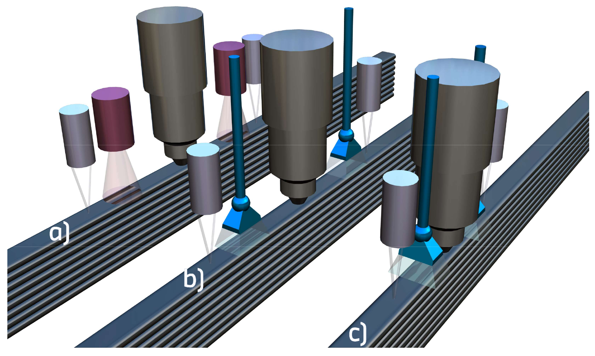
A rectangle was chosen as the part geometry, with one side hanging over the manufacturing base to allow constant extrusion during the required holding times, which were implemented to achieve long layer durations at a constant heat chimney. Two infrared emitters of type 1 × 150 W, 17 V, 9A by OPTRON GmbH, Garbsen, Germany, were installed in line with the long sides of the rectangle. One heater preceded the deposition nozzle by 100 mm, and one followed it at 100 mm distance with a focus point directly on the substrate surface and constant 100% emitter power. They were spaced with an additional 50 mm in each direction followed the two-infrared pyrometer LT-CF1-CB15 by Micro-Epsilon Messtechnik GmbH & Co. KG, Ortenburg, Germany, as shown in
Figure 1. Previous investigations already determined correction factors across the entire 20–300 °C temperature range for the infrared pyrometers in relation to much more accurate tactile measurements. These correction factors were applied to all infrared temperature data collected throughout this study. The screw speed was set to identical extrusion velocities as traversing velocities, so that the strand is neither pulled nor pushed, creating forced flow.
The extrusion and heating zone temperatures, as well as the layer height of 1.0 mm, were kept constant at the already optimized levels for a robust process. The build space remained unheated and experienced a ±2 °C variation in ambient temperature during the manufacturing process, which is also the most significant disturbance variable in the industrial FEAM process. Since the substrate is heated once more between the preceding infrared pyrometer and the actual deposition of the next layer, the impact of the last heater was determined numerically in separate experiments based in relation to the temperature recorded by the preceding pyrometer. For each temperature–velocity setup, a corresponding part was manufactured with multiple samples in the longitudinal x-direction cut in the first long side of the rectangle, while multiple samples in the transverse z-direction were cut from the second long side.
2.2. Cooling Wide
The DoE for cooling the substrate temperature was quite similar to that of the heating experiment. Instead of infrared heaters, pressurized air was emitted from 1/4-inch flared nozzles. The infrared pyrometers were mounted at the same distance of 150 mm preceding and following the extrusion nozzle, and the air nozzles were placed between them at distances of 100 mm from the extrusion nozzle.
Again, the full factorial investigation aimed to test experimental setups of different traversing velocities
(0.080 m/s and 0.160 m/s) and various substrate temperatures
. Contrary to the heating experiments, it was not possible to determine the substrate temperature prior to cooling, as the substrate temperature exceeded the melt temperature of 221 °C [
12], and the parts collapsed. Therefore, the target temperature of the leading pyrometer during cooling was chosen as the second independent variable. The actual temperature at deposition had to be determined by additional experiments to capture the effect of the second cooling nozzle, which cools the substrate after the last pyrometer passes and before the new strand is extruded. The target leading temperatures we aimed for spanned the entire process window at 130 °C, 150 °C, 170 °C, and 210 °C with a tolerance of ±2 °C. At substrate temperatures below 130 °C, the tensile properties lead to delamination, and for substrate temperatures above 216 °C, the part simply melts. The dependent variables investigated were, as in the heating experiment, the tensile strength and modulus; however, they were only investigated in the z-direction as the parts manufactured had to be so small in circumference that a sufficiently large longitudinal sample could not be taken.
The distances were kept constant between the extrusion nozzle and the infrared pyrometers, as well as to the 1/4-inch flared cooling nozzles parallel to the strand. Other control variables included the volume flow of pressurized air at 50% of its maximum volumetric output, the screw speed, which corresponded to the specific traversing velocity, the heat zone temperatures, and the layer height. Due to the short layer times and reduced part size, only two to four transverse samples resulted from a single part. Therefore, each setup was manufactured multiple times until a sufficient number of samples were obtained. To avoid the effect of an altered heat chimney when reducing the part sizes, one of the long sides of the rectangle was positioned over the edge of the assembly bed, allowing the manufacture of a single wall with continuous circular movements.
During manufacturing, it became apparent that only low temperatures could be realized, as the part would have to be smaller than possible to achieve shorter layer times and higher temperatures. Due to the large distance of 200 mm between the cooling nozzles and 300 mm between the pyrometers, the part size could not be reduced sufficiently. The next section presents a second stage of the cooling experiment with an adapted setup, which allowed all temperatures and velocities to be manufactured.
2.3. Cooling Narrow
The setup of the previous section was adjusted by aligning the flared ¼-inch nozzles perpendicular to the strand rather than parallel to it, by increasing the air flow to 100%, and by adjusting the distances between the sensors. The pressurized air cooling nozzles were moved closer to the extrusion nozzle to a distance of 50 mm each, and the infrared pyrometers were set at 100 mm distance to the extrusion nozzle. The target temperatures were adjusted to the actual process window to 150 °C, 170 °C, 180 °C, and 190 °C, while the field of traversing velocities was subdivided to cover 0.080 m/s, 0.120 m/s, and 0.160 m/s. All other variables were kept identical to the method outlined in the previous section. A detailed overview of all manufactured and tested setups for heating and cooling is provided as separate tables in
Appendix A.
Figure 1.
Schematic representation of the three manufacturing setups: (a) heating, (b) wide cooling with aligned cooling nozzle, and (c) narrow cooling with perpendicular cooling nozzle and shorter cooling distance. Infrared heaters are depicted in red, cooling nozzles are depicted in blue.
Figure 1.
Schematic representation of the three manufacturing setups: (a) heating, (b) wide cooling with aligned cooling nozzle, and (c) narrow cooling with perpendicular cooling nozzle and shorter cooling distance. Infrared heaters are depicted in red, cooling nozzles are depicted in blue.
2.4. Sample Preparation and Testing
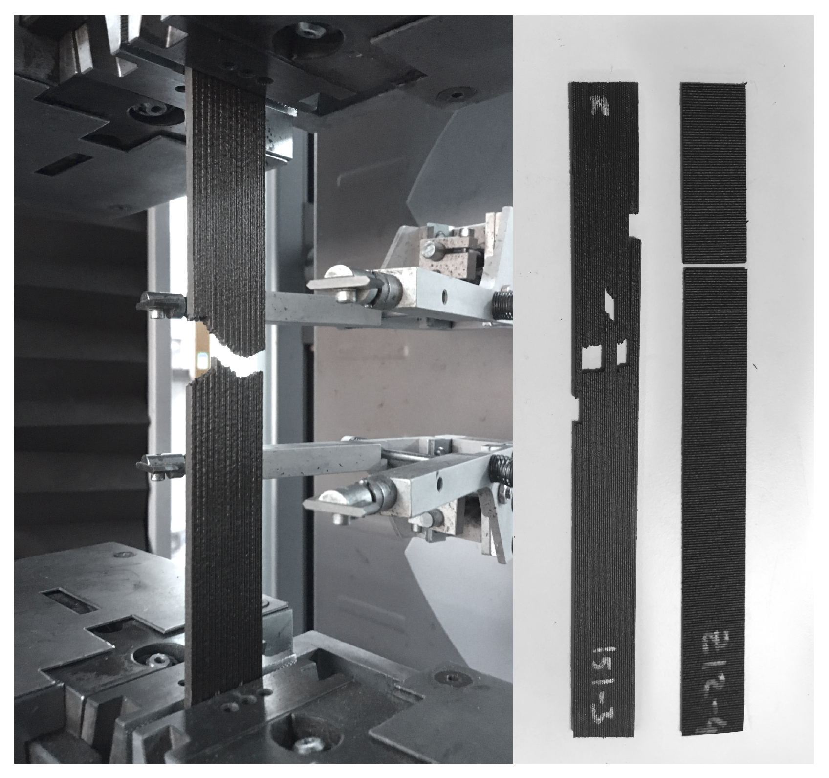
The sample preparation and testing was identical for all three sub-investigations. With a part height of 300 mm, the top and bottom 25 mm were cut off to exclude all starting and finishing effects from the mechanical testing. In accordance with DIN EN ISO 527-4 [
22], the parts were then cut into 250 mm × 25 mm type 2 specimens using a water-cooled abrasive cutter. After manual deburring, the thickness and width of the samples were determined at various locations on the specimen as input for the tensile tests. All samples were labeled and then placed in a climatic chamber where they were conditioned for 10 days at 70 °C and at 62% relative humidity, as suggested by DIN EN ISO 1110 [
23].
Tensile tests were performed on a universal testing machine of type Z100/SN5A from ZwickRoell GmbH & Co. KG, Ulm, Germany. Test parameters were selected according to the standard to a preload of 50 N with 2 mm/min, a free gripping length of 150 mm, and a measuring length of the tactile strain gauge of 50 mm. The tensile modulus was determined between the 0.05% and 0.25% strain at 2 mm/min by secant. All tests were performed at a controlled room temperature of 23 °C. The fracture pattern and position were recorded for each specimen based on the fractured modes specified in ASTM D3039 [
24] to identify potential patterns.
Figure 2 presents the test setup in the universal testing machine after fracture as well as fractured specimens for both the x- and z-directions of testing.
The specimen thickness used to calculate the tensile strength and modulus corresponds to the strand width (~3.1 mm), not the contact width between successive strands. Therefore, to determine the nominal tensile strength and tensile modulus of the bulk material, the specimen thickness had to be adjusted to the contact width. To determine the contact width, small samples were taken for all setups and examined under an optical microscope, measuring the specific contact width between 10 layers and using the average value as input for nominal specimen thickness. For both the standard and nominal tensile results, the mean values and standard deviations of five samples per setup were determined.
3. Results
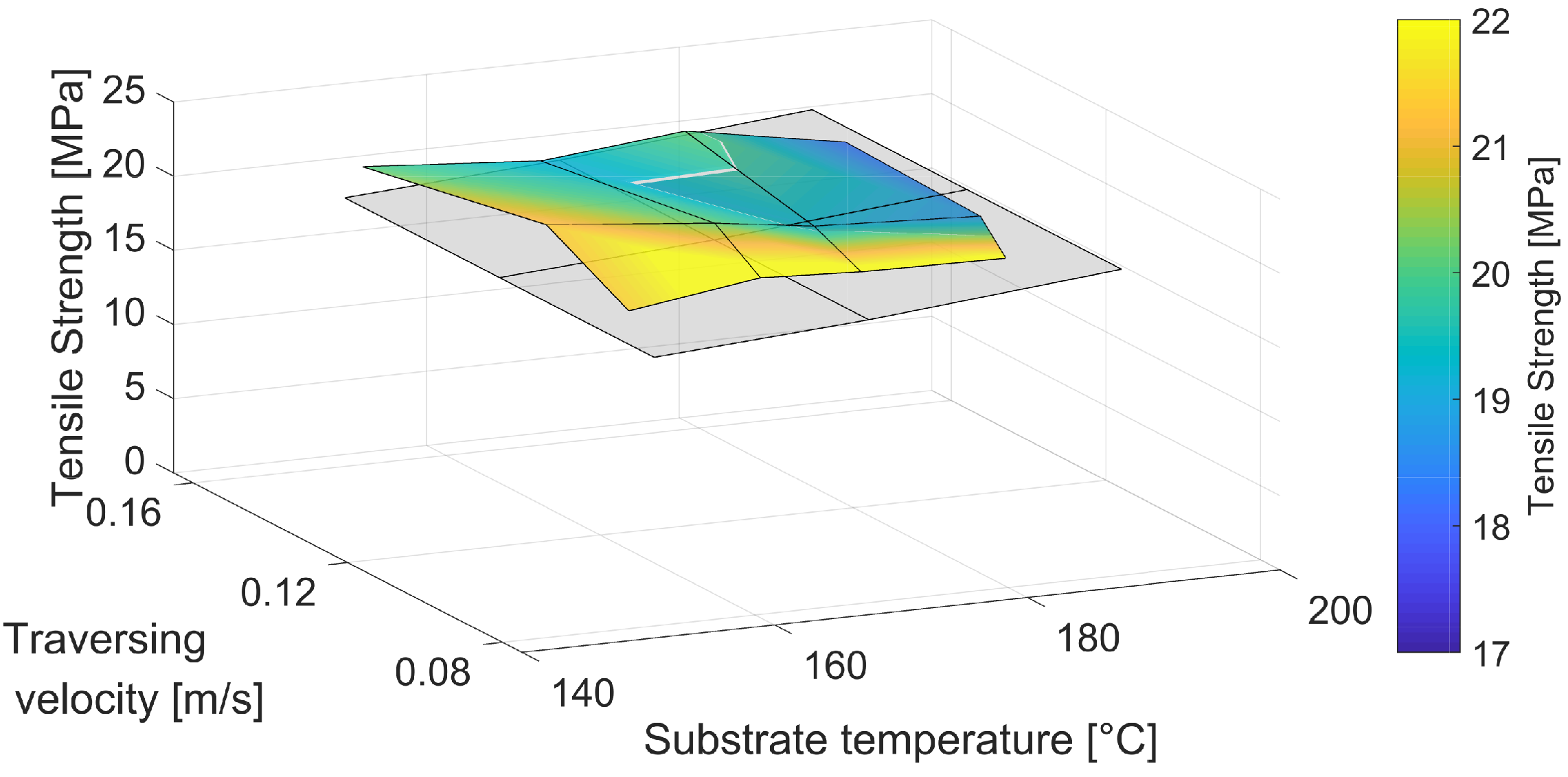
3.1. Heating
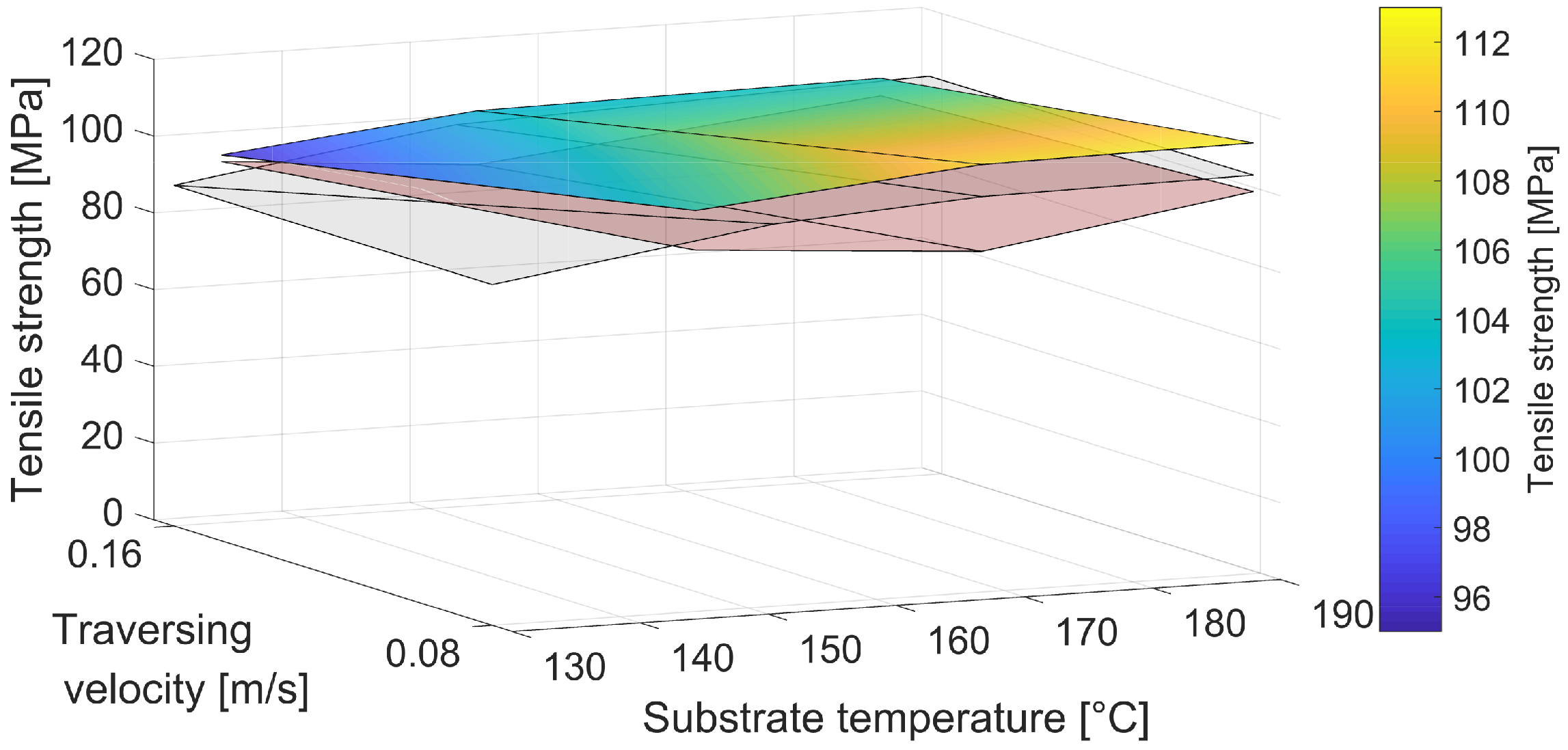
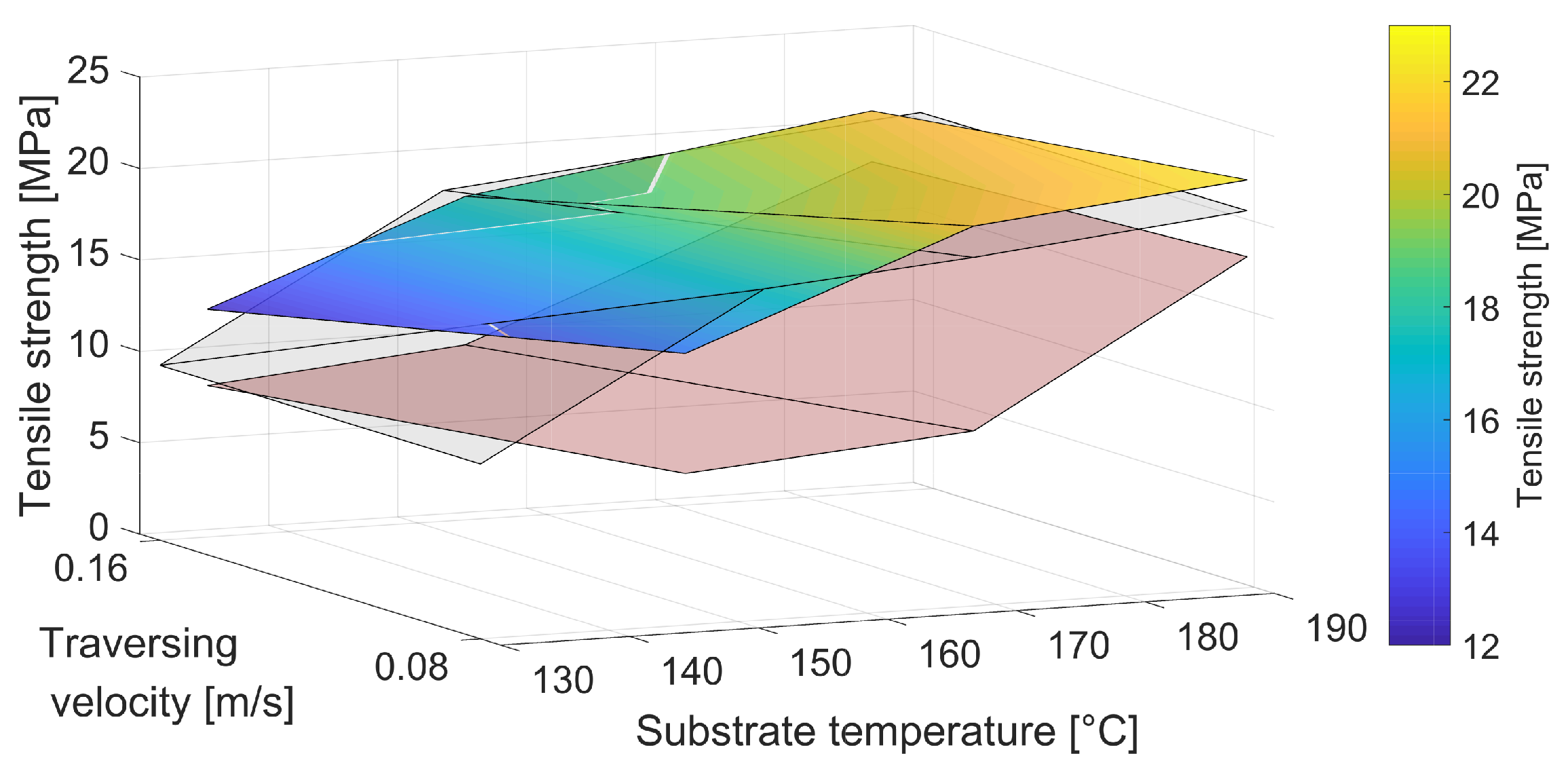
Figure 3 and
Figure 4 depict the tensile strengths of the heated samples in the longitudinal (x) and transverse (z) directions as a gradient map. Since for each part and thus each layer time, the heated and unheated substrate temperatures were determined, this gradient map, in contrast to two-dimensional representations, enables the comparison of the obtained values with the tensile strength of unheated specimens at the original unheated substrate temperature and the final heated substrate temperature. Furthermore, it visualizes the trends of different traversing velocities and increasing substrate temperatures on the tensile strength obtained for both heated and unheated specimens. The colored gradient map represents the main results achieved by the heated specimen. The red surface illustrates the tensile test results obtained from unheated parts at the base unheated substrate temperature recorded at the identical layer time. In contrast, the gray surface represents the tensile strengths of unheated specimens directly manufactured at the final heated substrate temperature. According to the hypothesis that the substrate temperature is the most decisive factor in the bond strength formation, the gray surfaces should correlate closely with the heated results.
The heated samples exhibit slightly higher longitudinal tensile strengths than the unheated specimens at the target temperature. As expected, this represents a significant increase in tensile strength compared to the results of the base temperature samples. This is even more evident in the transverse tensile strength, where the additional heat almost doubled the tensile strength around the target temperature of 160 °C compared to the tensile strength at the base temperature of 130 °C.
The tensile modulus,
, was calculated by the secant slope [
23] between the strain values
= 0.0005 = 0.05% and
= 0.0025 = 0.25% and the respective stresses
and
in megapascal:
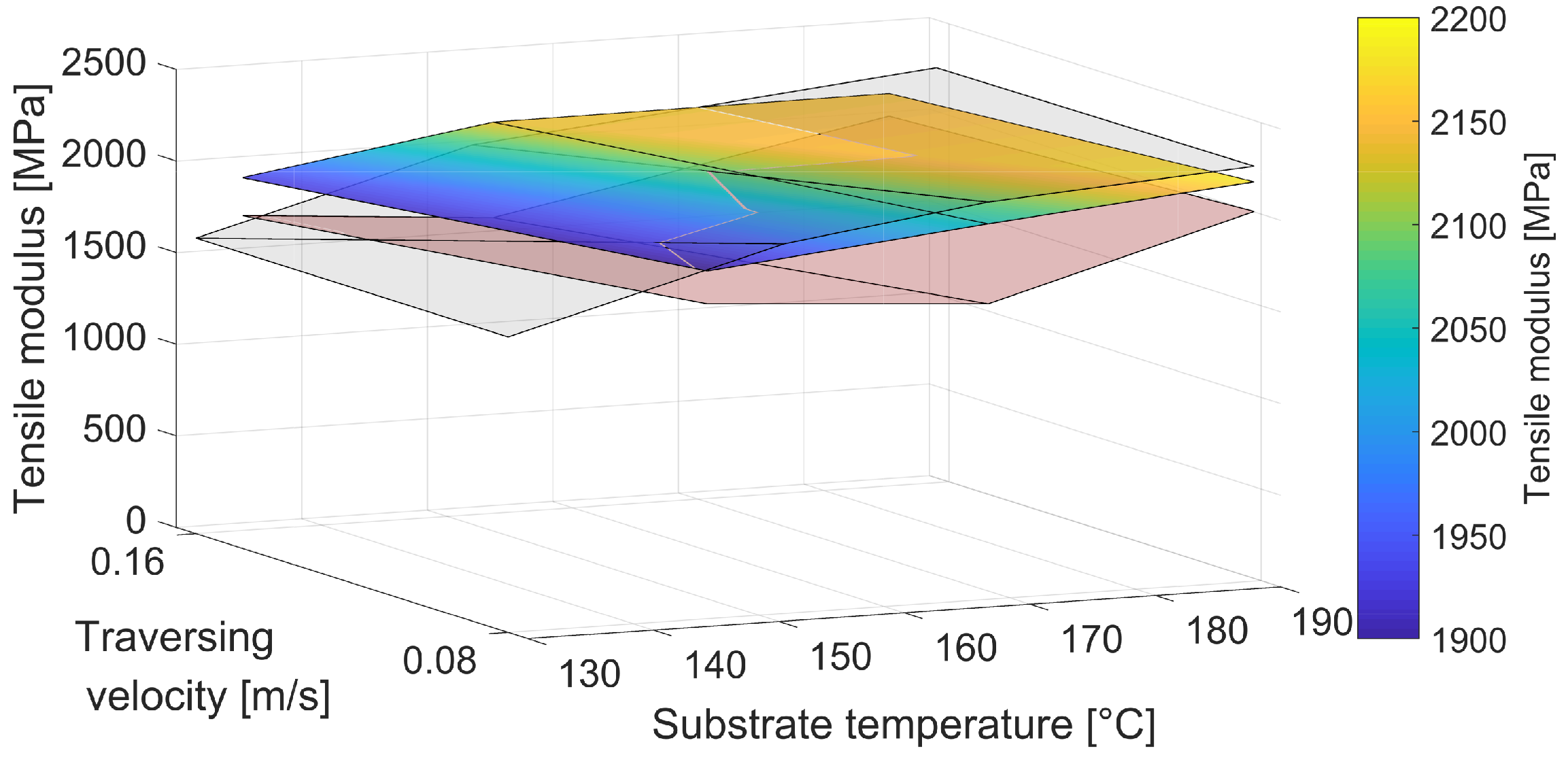
The results of the tensile modulus, as shown in
Figure 5, support the above findings; however, the tensile modulus in the transverse direction yielded slightly lower results than the original test at the target temperature. Nevertheless, the increase over the base temperature is significant.
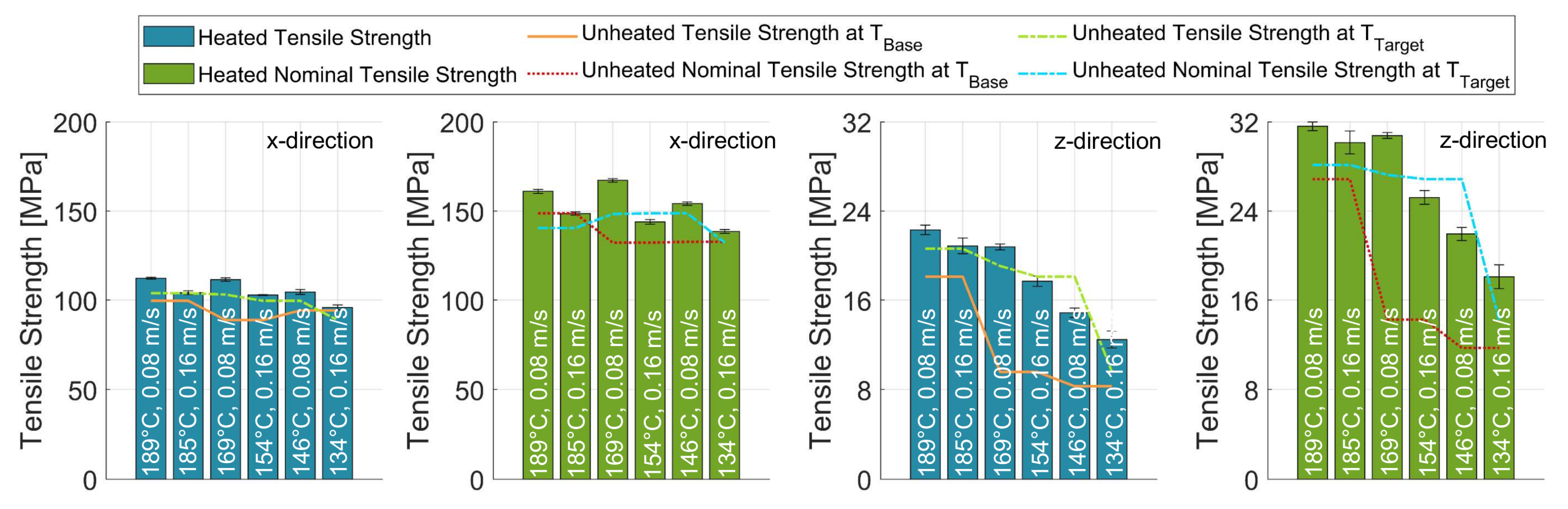
Figure 6 depicts an overview of the standard and nominal results of the tensile strength for the heated samples in both the longitudinal and transverse direction. The plots in the z-direction show slightly higher values for setups manufactured at 0.080 m/s. In previous investigations, the tensile strength in the longitudinal direction varied only minimally even with decreasing temperatures, since the strength is mainly dependent on the strength of the bulk of the strand. The heated results showed the same effect compared to the transverse results, which mainly depend on temperature-driven fusion bonding mechanisms across the interface [
7,
10,
15]. Thus, the decrease in tensile strength with lower temperatures is much more significant in the transverse direction, as seen in the two right-hand plots in
Figure 6. Here, the heated nominal tensile strengths represent the strength when analyzed over the actual cross-section of the contact interface between successive strands. In this case, the contact width was considered instead of the strand width. The error bars present the obtained standard deviations, suggesting very little variation between different samples and parts.
All heated setups yielded tensile strengths well above their base temperatures. At the higher temperatures of 169 to 189 °C, which are still within the optimized processing window, the heated tensile strength even exceeded the results of the unheated target temperatures. As expected, the temperatures below this yielded only slightly lower results. The tensile modulus produced similar trends to those of the tensile strength, which overall confirmed that by the use of infrared heaters, the substrate temperature can be raised effectively. The heating increased the substrate temperature between +21 °C at high traversing velocities and low base temperatures and +39 °C at 0.080 m/s and a base temperature of 150 °C.
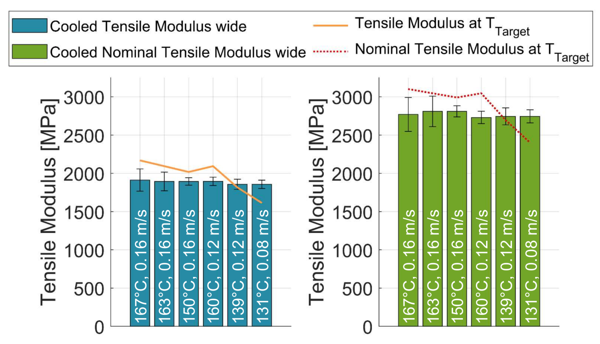
3.2. Cooling Wide
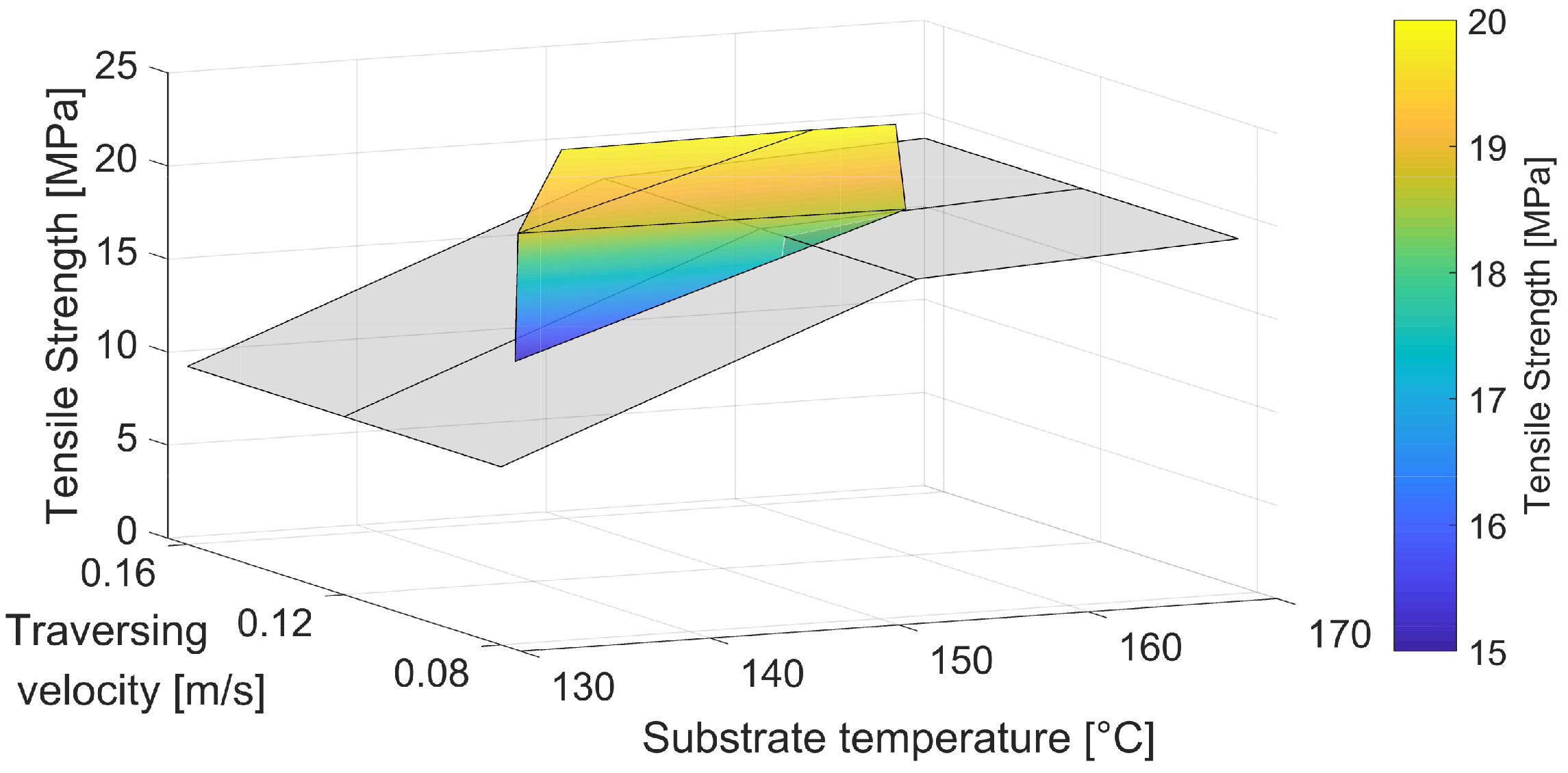
Since no base temperature could be measured for the cooling experiments due to melting of the polymer at higher temperatures,
Figure 7 shows the tensile strength of the cooled specimens at a wide cooling distance of 100 mm without a surface for base values. Again, the gradient map represents the results of the cooled samples, while the gray surface reflects the results of the uncooled samples from unmanipulated experiments.
While the gray surface was spanned across all velocities, the strength values were determined only for samples manufactured at 0.160 m/s without any temperature manipulation through cooling. While these reference measurements were performed at distinctive chosen temperatures, the color map represents the resulting tensile strengths of the manipulated substrate temperatures, obtaining a disordered distribution of the temperatures. As briefly mentioned before, the large distance between the cooling nozzles did not allow for sample manufacturing at substrate temperatures above the melt temperature, and thus, only an excerpt of the original DoE for wide cooling was feasible, since the part size could not be sufficiently reduced to achieve the desired layer times at the given traversing velocities.
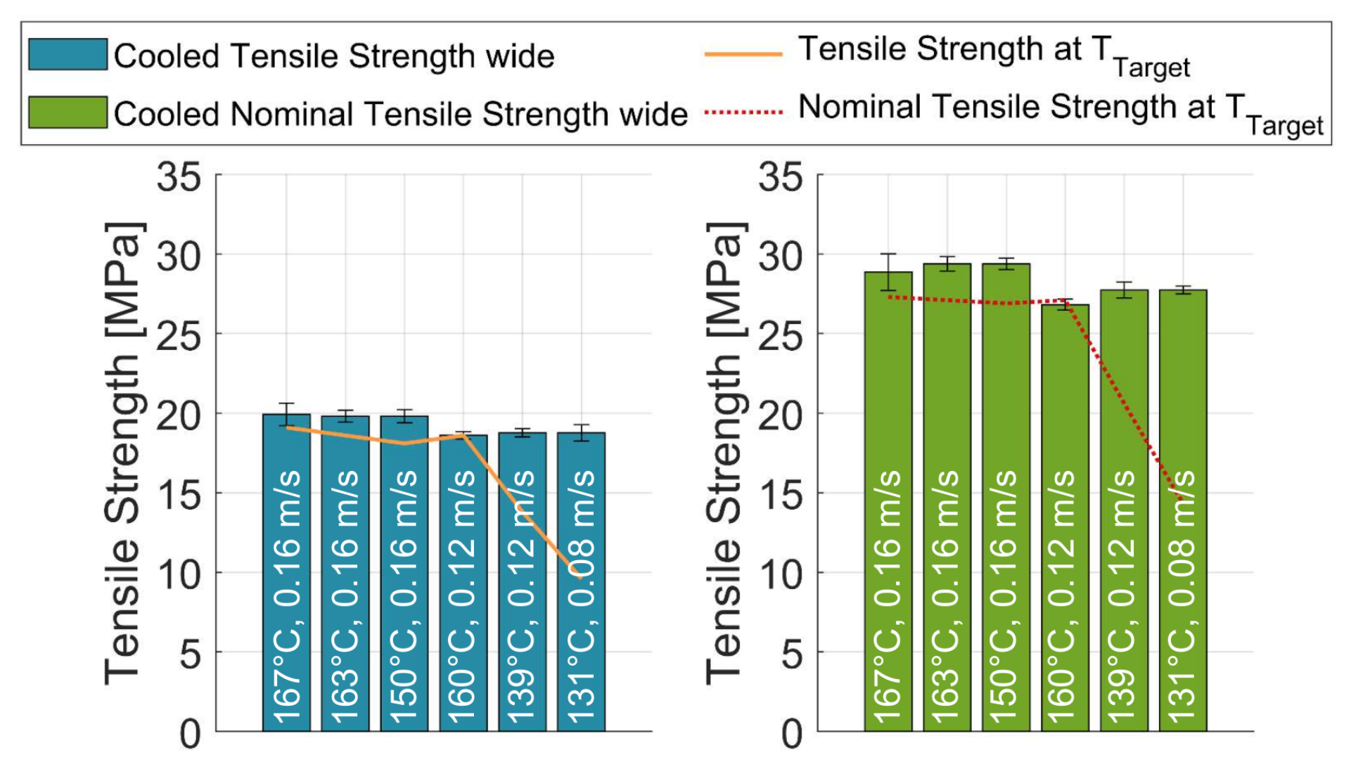
The surface in
Figure 7 and the bar chart results of
Figure 8 present that the tensile strength in the transverse direction consistently yielded identical or higher results than those of the unheated counterparts. This was independent of the actual traversing velocity or the resulting substrate temperature for both the single strand and nominal bulk material tensile strength. Based on the unheated specimen, there was a significant reduction in tensile strength below the suggested processing window [
12] and thus below the onset of crystallization. However, the temperatures 139 and 131 °C, which fell below this limit, yielded nearly as high tensile strengths as the hotter samples.
Similar to the heated experiments, the tensile modulus remained in the range of, but slightly below, most of the target values, as shown in
Figure 9. It is also noticeable that there is barely any difference in the values achieved, independent of the actual temperature, even though the reference values drop considerably when manufacturing outside of the process window.
While no overall cooling effect can be numerically determined without a measurable base temperature, the effect of the final air nozzle was determined between −22 and −36 °C at 170 °C as the lowest target temperature and −50 °C at the highest target temperature of 216 °C.
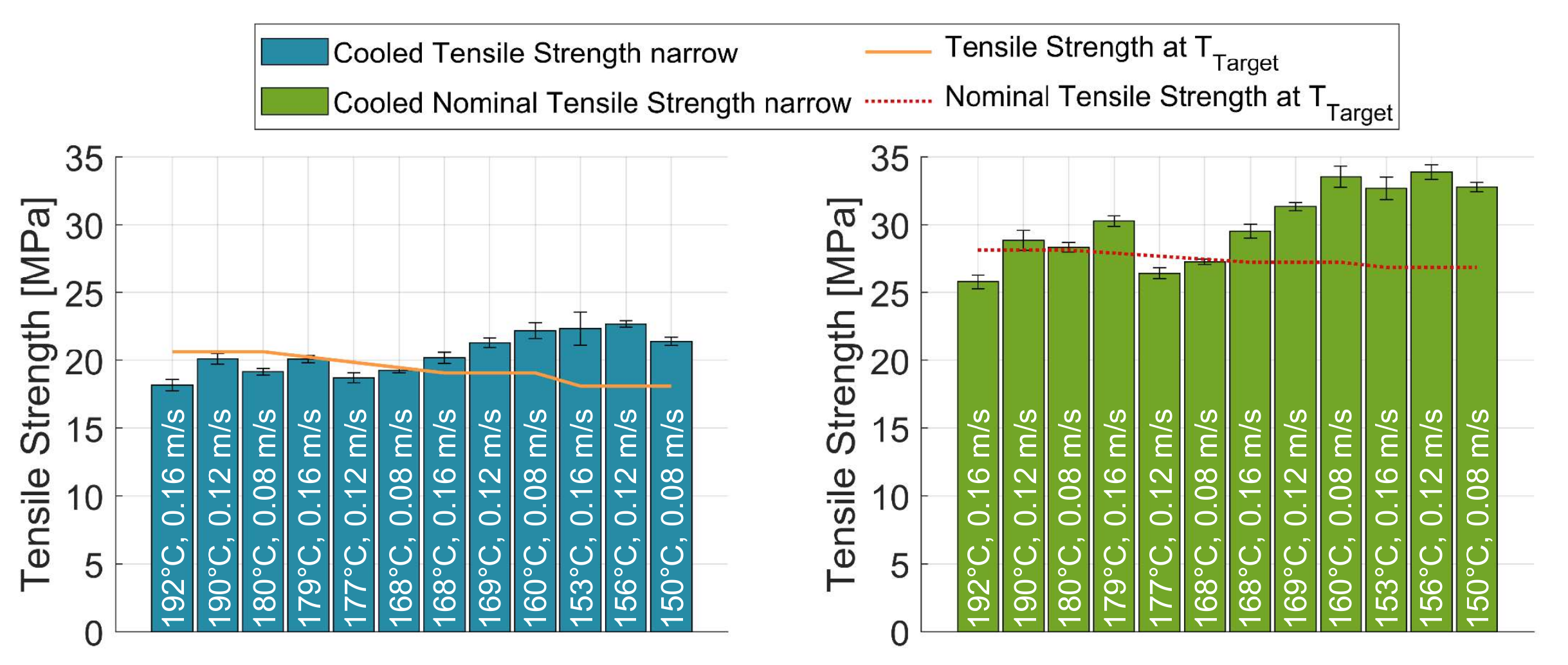
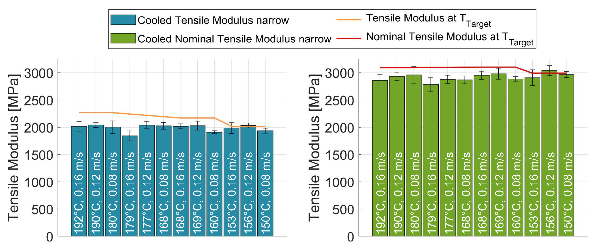
3.3. Cooling Narrow
In order to cater to all four target temperatures over the full range of traversing velocities, the setup was adapted and the sensor spacing reduced.
Figure 10 and
Figure 11 present the results of the tensile strength in the transverse direction at 50 mm cooling distance and with a perpendicularly arranged nozzle in comparison to uncooled samples at the final substrate temperature.
At high temperatures, the narrow-cooled experiments yielded tensile strengths slightly below the expected target values in transverse direction. At the same time, the results at temperatures below 169 °C increasingly exceeded the target values at all velocities. There was no discernible trend for the various velocities between 0.080 and 0.160 m/s. The results of the narrow cooling experiment yielded higher tensile strengths than the wide experiments.
Figure 12 depicts the tensile modulus of the narrowly cooled tests. Analogous to the previous series, the tensile moduli homogeneously remained just below the target values. The cooling effect of the final air nozzle with double the throughput, but in a perpendicular position to the strand, resulted in cooling effects of −11 °C at 0.160 m/s and the lowest target temperature and −39 °C at 0.080 m/s and the highest target temperature.
4. Discussion
The results of this study act as a basis for detailed parameter investigations for targeted temperature manipulations. To employ large-scale EAM technologies in industrial applications, it is not only necessary to be able to influence the substrate temperature according to the component’s requirements but also to engineer the mechanical properties in a defined manner. For this, we compared the results from the manipulated samples to the tensile properties obtained from unheated and uncooled samples at identical temperatures, which were all collected at a traversing speed of 0.160 m/s after determining no influence of the velocity itself on the thermal behavior without active temperature manipulation, since only the layer duration affected the achieved substrate temperature.
The infrared heating experiments were consistent with the hypothesis that the interlayer bond strength is a function of the substrate temperature, and when this is actively increased, the bond strength converges to that of unheated samples manufactured at that exact target temperature. This is particularly visible in the close agreement of the heated results. For these, the gray surfaces in
Figure 3,
Figure 4 and
Figure 5 represent the achieved tensile strength and modulus for unmanipulated or unheated samples at the representative heated substrate temperatures of this investigation. It was expected that the strength and modulus should rise from the level of the red surface, which corresponded to unheated samples at the identical layer time, to that of the gray surface. As can be seen in
Figure 3,
Figure 4 and
Figure 5, the tensile modulus remained slightly below the target values at higher substrate temperatures, while the tensile strength even exceeded the target strength for most setups. This was attributed to be more an effect of difficult determination of the actual substrate temperature at deposition than to be relevant and significant process behavior.
The numerical results in the transverse direction showed a trend toward higher tensile strengths for the setups manufactured at 0.080 m/s compared to those at 0.160 m/s. This may be due to the twice as long passing time of the infrared emitters over each point of the path and thus a higher heat input, which in turn affects the crystallinity within each strand, leading to higher tensile strengths. At higher target temperatures, which are within the ideal processing window, the tensile strength exceeded the expected reference strength considerably, while the lower temperatures resulted in tensile strengths slightly lower than expected. This may again be due to greater crystal growth at lower temperatures, which may not get fully melted upon reheating at moderate temperatures, leading to limited fusion bonding across the interface [
25].
It must also be noted that the impact of the heating process was considerably higher for lower substrate temperatures in regard to the tensile strength. Samples at unmanipulated substrate temperatures below the mentioned processing window, and thus below the onset of crystallization, obtained significantly lower tensile strengths compared to substrate temperatures within the processing window. Through infrared heating, these low-strength values were considerably increased, yielding an increase in strength of up to 32% for the single-walled tensile strength with regard to the strand width and up to 37% for the nominal tensile strength. While the tensile modulus did not obtain such strong increases, an improvement of up to 12% for the overall tensile modulus and up to 17% for the nominal tensile modulus were determined.
Similar to the heating series, both cooling test series reinforced the idea of a relationship between the substrate temperature and the resulting tensile strength. However, the tensile strengths of the widely cooled samples did not drop for lower temperatures, as expected by the hypothesis. The reason might be that the surface temperature is cooled to the measured temperatures, but a higher core temperature of the strands leads to slower cooling of the interface after deposition and thus may lead to a higher degree of bond and higher tensile strength as expected. Furthermore, this would suggest that the interface temperature remains at higher temperatures for longer, reducing the hindrance of molecular motion due to the increasing crystallinity in the polymer. While the higher substrate temperatures yielded only moderate increases of 1–7% compared to the unheated samples at identical substrate temperatures, the tensile strength of the lower samples was increased by up to 59%.
The tensile modulus was also expected to be congruent to that of the unmodified samples; however, all three series showed that the tensile modulus remained slightly below the expected target values. All setups yielded tensile moduli between +4% and −11% of the unmanipulated reference samples. The authors suggest that this is due to the different morphology formed under the manipulated thermal conditions, which would best be analyzed through a thorough study of the crystallinity of the different experimental setups.
Similar to the widely cooled experiments, the narrow cooling experiments with decreased cooling distance yielded higher tensile strengths compared to the unmanipulated reference samples. Numerically, the maximum increase of up to 23% in tensile strength was lower than in the wide tests, since only the processing window down to 150 °C was considered in the narrow experiments. The samples of the highest temperature and traversing velocity yielded even slightly lower tensile strengths than the reference values. This was attributed to the high temperatures potentially affecting the mesostructure and the final way of layer-to-layer adhesion, which should be further analyzed through more detailed 2D micrographs or 3D X-ray computed tomography scans.
A limit of this study is the comparatively simple design of experiment. To fully characterize the effect of cooling and heating, a lot more temperatures and traversing velocities, the heating power, and the cooling volume throughput would have to be varied on a much larger scale. For the sake of a feasibility study, the scope of this investigation allows a first judgment about likely influences as well as the overall potential of the approach. Additionally, with the objective of optimizing processing parameters for maximum attainable layer adhesion, the potential of post-processing treatments such as annealing was not investigated. For standard FFF processes, high-temperature post-processing treatments slightly increased the tensile strength and even reduced the porosity while increasing crystallinity within the component [
26]. This provides a basis for further investigation of post-processing treatments to improve mechanical properties.
Since in all test series, there was a heating or cooling element between the trailing pyrometer and the extrusion nozzle, the final substrate temperature immediately prior to deposition had to be determined in separate tests. This did not affect the tensile measurements or the individual results, but it shifted the data points to higher or lower calculated target temperatures. Care has been taken to ensure that these separate measurements were aligned in the best way possible with the actual tests to reduce as much variance and uncertainty as possible.
The thermal radiation from the extrusion unit may also have influenced the temperature signal, especially for the narrow cooling series with only 100 mm distance between measuring point and extrusion nozzle. Reference tests were performed for all series to confirm that this distortion is negligible in the given setup. Fusion bonding mechanisms and crystallization behavior related to the reheating and rapid cooling were not investigated in this paper. The authors suggest a thorough material investigation of the crystallization behavior for more in-depth studies and to gain a better understanding of the material behavior, especially for cooled parts.
5. Conclusions
The increase in part size and complexity in large-scale additive manufacturing has led to the need for targeted temperature manipulation within the process. With previous research confirming that the fusion bonding process is a largely temperature-controlled phenomenon, the hypothesis was presented that the mechanical properties of additively manufactured polymer parts could be tailored through the use of targeted heating or cooling. These heating and cooling mechanisms and their impact become increasingly relevant in large-scale extrusion additive manufacturing approaches in the automotive or aerospace sector, where large dimensions can only be achieved through systems without envelope heating or ambient temperature control. Through the use of a robot-based system and pelletized feedstock instead of filaments, the throughputs could be significantly increased to reach wall thicknesses comparable to injection molding around 3 mm. With samples manufactured with the FEAM cell at the BMW plant Landshut, tensile tests were chosen as readily available mechanical testing method to allow comparison to other EAM systems. Due to the extrusion unit being robot-based, the heating and cooling equipment had to be compact and easily integrable in a small installation space with flexible positioning. After hot air heating only obtained unsatisfying increases of the substrate temperature, a double infrared emitter system was installed for heating. Effective and robust cooling was achieved through pressurized air supplied 360° around the deposition nozzle by three separate slit nozzles.
The hypothesis that the tensile properties after manipulation from a base temperature to a target substrate temperature would yield comparable results to unmanipulated samples at the specific target temperatures was confirmed for both heating and cooling. For the heating results, it was particularly interesting that the heated tensile samples yielded even significantly higher tensile strengths compared to the unmanipulated samples at the identical target temperature. Furthermore, the impact of the infrared emitters on the tensile strength increased for lower substrate temperatures, especially below the ideal processing window. Overall, the substrate temperature of large parts with long layer times was successfully raised by the infrared heaters, achieving comparable tensile strength and tensile modulus to unheated samples at corresponding temperatures. For future integration of the FEAM process in the automotive prototyping environment, this means that large and complex parts that exceed today’s target later times due to increasingly long path lengths can be successfully manufactured without forfeiting the mechanical strength of the resulting part.
In similar experimental setups, the cooling potential by pressurized air was investigated. Contrary to the hypothesis, the tensile strength obtained from the cooled samples yielded higher results than the comparable unmanipulated reference samples printed directly at the final substrate temperature. Particularly for tall parts with small cross-sections and thus very short layer paths, such as greenhouse pillars for vehicle prototyping, this is a significant improvement of the process. A now possible increase in traversing velocity reduces the printing time significantly, while ensuring dimensional accuracy, shape retention, and satisfying mechanical properties. It also became apparent that the tensile strength and modulus at lower substrate temperatures did not decline as much as predicted by the reference samples. It is suggested that this should be attributed to the cooling mostly affecting the outer surface of the strand with the core temperature remaining significantly higher than in the colder reference samples. This would lead to increased interface temperatures of the cooled samples and thus higher fusion bonding. To further investigate this thermal behavior, the authors suggest tactile measurements of manipulated and unmanipulated samples at the layer-to-layer interface.
Both heating and cooling have been shown to have a direct impact on the mechanical performance and geometric integrity of a part. Allowing for layer times outside of the material’s unmanipulated process window enables the manufacturing of a much wider range of parts. Overall, this study ascertained the great potential of targeted temperature manipulation in large-scale additive manufacturing and has laid the groundwork for more advanced characterizations for the reheating and rapid cooling of thermoplastic composites. There are five main suggestions for further investigations:
More detailed heating experiments with 360° heating around the deposition nozzle at different heating distances;
Detailed analyses of the crystallization and resulting mesostructure of unmanipulated as well as heated and cooled samples;
Tactile interface temperature determination through thermocouples, especially for the cooled samples to understand the increased strength at lower substrate temperatures;
Flexural testing of identical setups to verify that a corresponding effect of temperature manipulation is found for flexural strength and modulus;
Annealing investigation for post-processing at high temperatures.
Author Contributions
Conceptualization, N.T.; methodology, N.T.; validation, N.T.; formal analysis, N.T.; investigation, N.T.; resources, N.T.; data curation, N.T.; writing—original draft preparation, N.T.; writing—review and editing, N.T., T.A.O. and K.D.; visualization, N.T.; supervision, T.A.O. and K.D.; project administration, N.T. All authors have read and agreed to the published version of the manuscript.
Funding
This research received no external funding.
Institutional Review Board Statement
Not applicable.
Informed Consent Statement
Not applicable.
Data Availability Statement
The data presented in this study are available on request from the corresponding author.
Acknowledgments
We thank the materials and process analysis department of the BMW Group Landshut for providing testing facilities, laboratory equipment and climate chambers. We also show our gratitude to our colleague Denis Vetters for his input during manufacturing and processing of the test specimens.
Conflicts of Interest
The authors declare no conflict of interest.
Abbreviations
The following abbreviations are used in this manuscript:
| AM | Additive Manufacturing |
| EAM | Extrusion Additive Manufacturing |
| FEAM | Freeform Extrusion Additive Manufacturing |
| DCB | Double Cantilever Beam |
| FFF | Fused Filament Fabrication |
| PLC | Programmable Logic Controller |
| DoE | Design of Experiments |
Appendix A
In the following,
Table A1–
Table A3 present the different setups manufactured and tested in this study for all heating and cooling experiments. Details on the setups are provided in
Section 2.
Table A1.
Manufactured and tested heating setups for an emitter power of 100% and a heating distance of 100 mm.
Table A1.
Manufactured and tested heating setups for an emitter power of 100% and a heating distance of 100 mm.
Traversing
Velocity | Unheated
Substrate
Temperature | Heated
Substrate
Temperature | Direction | Number of
Specimens |
|---|
| 0.160 | 151 | 185 | x | 5 |
| z | 5 |
| 130 | 154 | x | 5 |
| z | 5 |
| 112 | 134 | x | 5 |
| z | 5 |
| 0.080 | 151 | 189 | x | 5 |
| z | 5 |
| 130 | 168 | x | 5 |
| z | 5 |
| 109 | 146 | x | 5 |
| z | 5 |
Table A2.
Manufactured and tested wide cooling setups for a volumetric throughput of the pressurized air of 50% and a cooling distance of 100 mm.
Table A2.
Manufactured and tested wide cooling setups for a volumetric throughput of the pressurized air of 50% and a cooling distance of 100 mm.
Traversing
Velocity | Layer Time | Cooled Substrate
Temperature | Direction | Number of
Specimens |
|---|
| 0.160 | 4.7 | 167 | z | 4 |
| 4.9 | 166 | z | 5 |
| 5.1 | 163 | z | 5 |
| 7.2 | 150 | z | 5 |
| 0.120 | 5.0 | 160 | z | 5 |
| 6.7 | 139 | z | 5 |
| 0.080 | 7.5 | 131 | z | 5 |
Table A3.
Manufactured and tested wide cooling setups for a volumetric throughput of the pressurized air of 100% and a cooling distance of 50 mm.
Table A3.
Manufactured and tested wide cooling setups for a volumetric throughput of the pressurized air of 100% and a cooling distance of 50 mm.
Traversing
Velocity | Layer
Time | Cooled
Substrate
Temperature | Direction | Number of
Specimens |
|---|
| 0.160 | 7.2 | 192 | z | 5 |
| 8.8 | 179 | z | 4 |
| 9.8 | 168 | z | 5 |
| 13.4 | 153 | z | 5 |
| 0.120 | 7.1 | 190 | z | 5 |
| 8.3 | 177 | z | 5 |
| 9.6 | 169 | z | 4 |
| 12.5 | 156 | z | 5 |
| 0.080 | 4.6 | 180 | z | 5 |
| 5.4 | 168 | z | 5 |
| 7.3 | 160 | z | 5 |
| 10.6 | 150 | z | 5 |
References
- Go, J.; Schiffres, S.N.; Stevens, A.G.; Hart, A.J. Rate limits of additive manufacturing by fused filament fabrication and guidelines for high-throughput system design. Addit. Manuf. 2017, 16, 1–11. [Google Scholar] [CrossRef]
- Duty, C.E.; Kunc, V.; Compton, B.; Post, B.; Erdman, D.; Smith, R.J.; Lind, R.; Lloyd, P.; Love, L.J. Structure and mechanical behavior of Big Area Additive Manufacturing (BAAM) materials. Rapid Prototyp. J. 2017, 23, 181–189. [Google Scholar] [CrossRef]
- Khorasani, M.; Ghasemi, A.; Rolfe, B.; Gibson, I. Additive manufacturing a powerful tool for the aerospace industry. Rapid Prototyp. J. 2022, 28, 87–100. [Google Scholar] [CrossRef]
- Ahn, S.H.; Montero, M.; Odell, D.; Roundy, S.; Wright, P.K. Anisotropic material properties of fused deposition modeling ABS. Rapid Prototyp. J. 2002, 8, 248–257. [Google Scholar] [CrossRef] [Green Version]
- Durgun, I.; Ertan, R. Experimental investigation of FDM process for improvement of mechanical properties and production cost. Rapid Prototyp. J. 2014, 20, 228–235. [Google Scholar] [CrossRef]
- Malguarnera, S.C.; Manisali, A. The effects of processing parameters on the tensile properties of weld lines in injection molded thermoplastics. Polym. Eng. Sci. 1981, 21, 586–593. [Google Scholar] [CrossRef]
- Nahar, C.; Gurrala, P.K. Transient Thermal Finite-Element Analysis of Fused Filament Fabrication Process. Available online: https://doi.org/10.1108/RPJ-05-2021-0104 (accessed on 14 February 2022).
- Rodríguez, J.F.; Thomas, J.P.; Renaud, J.E. Mechanical behavior of acrylonitrile butadiene styrene (ABS) fused deposition materials. Experimental investigation. Rapid Prototyp. J. 2001, 7, 148–158. [Google Scholar] [CrossRef]
- Watanabe, N.; Shofner, M.L.; Rosen, D.W. Tensile mechanical properties of polypropylene composites fabricated by material extrusion. In Proceedings of the Solid Freeform Fabrication Symposium—An Additive Manufacturing Conference, Austin, TX, USA, 7–9 August 2017; pp. 633–646. [Google Scholar]
- Cavallo, D.; Gardella, L.; Alfonso, G.C.; Portale, G.; Balzano, L.; Androsch, R. Effect of cooling rate on the crystal/mesophase polymorphism of polyamide 6. Colloid Polym. Sci. 2011, 289, 1073–1079. [Google Scholar] [CrossRef]
- Consul, P.; Chaplin, A.; Tagscherer, N.; Zaremba, S.; Drechsler, K. Interlaminar strength in large–scale additive manufacturing of slow crystallizing polyaryletherketone carbon composites. Polym. Int. 2020, 70, 1099–1108. [Google Scholar] [CrossRef]
- Tagscherer, N.; Consul, P.; Kottenstedde, I.L.; Latiri, H.; Zaremba, S.; Drechsler, K. Investigation of nonisothermal fusion bonding for extrusion additive manufacturing of large structural parts. Polym. Compos. 2021, 42, 5209. [Google Scholar] [CrossRef]
- Padaki, S.; Drzal, L.T. Autohesive strength characterization of semi-crystalline polymer matrix composites. Compos. Interfaces 1996, 4, 133–142. [Google Scholar] [CrossRef]
- Stokes-Griffin, C.M.; Compston, P. Investigation of sub-melt temperature bonding of carbon-fibre/PEEK in an automated laser tape placement process. Compos. Part A Appl. Sci. Manuf. 2016, 84, 17–25. [Google Scholar] [CrossRef]
- Dinwiddie, R.B.; Kunc, V.; Lindal, J.M.; Post, B.; Smith, R.J.; Love, L.J.; Duty, C.E. Infrared imaging of the polymer 3D-printing process. In Proceedings of the Thermosense: Thermal Infrared Applications XXXVI; SPIE Proceedings; Colbert, F.P., Hsieh, S.J.T., Eds.; SPIE: Bellingham, WA, USA, 2014; p. 910502. [Google Scholar] [CrossRef]
- Kishore, V.; Ajinjeru, C.; Nycz, A.; Post, B.; Lindahl, J.; Kunc, V.; Duty, C.E. Infrared preheating to improve interlayer strength of big area additive manufacturing (BAAM) components. Addit. Manuf. 2017, 14, 7–12. [Google Scholar] [CrossRef]
- Boucher, E.; Folkers, J.P.; Creton, C.; Hervet, H.; Léger, L. Enhanced Adhesion between Polypropylene and Polyamide-6: Role of Interfacial Nucleation of the β-Crystalline Form of Polypropylene. Macromolecules 1997, 30, 2102–2109. [Google Scholar] [CrossRef]
- Riley, W.F.; Sturges, L.D.; Morris, D.H. Mechanics of Materials, 6th ed.; Wiley: Hoboken, NJ, USA, 2006. [Google Scholar]
- Zhuo, P.; Li, S.; Ashcroft, I.; Jones, A.; Pu, J. 3D Printing of Continuous Fibre Reinforced Thermoplastic Composites. In Proceedings of the 21st International Conference on Composite Materials, Xi’an, China, 20–25 August 2017. [Google Scholar]
- Ning, F.; Cong, W.; Hu, Y.; Wang, H. Additive manufacturing of carbon fiber-reinforced plastic composites using fused deposition modeling: Effects of process parameters on tensile properties. J. Compos. Mater. 2017, 51, 451–462. [Google Scholar] [CrossRef]
- Carneiro, O.; Silva, A.; Gomes, R. Fused deposition modeling with polypropylene. Mater. Des. 2015, 83, 768–776. [Google Scholar] [CrossRef]
- DIN Deutsches Institut für Normung e.V. DIN EN ISO 527-4:2022-03, Plastics—Determination of Tensile Properties—Part 4: Test Conditions for Isotropic and Orthotropic Fibre-Reinforced Plastic Composites. 2022. Available online: https://www.beuth.de/de/norm/din-en-iso-527-4/349810706 (accessed on 10 March 2022).
- DIN Deutsches Institut für Normung e.V. DIN EN ISO 1110:2019-09, Plastics—Polyamides—Accelerated Conditioning of Test Specimens. September 2019. Available online: https://www.beuth.de/de/norm/din-en-iso-1110/310232274 (accessed on 3 November 2019).
- ASTM International. ASTM D3039—Standard Test Method for Tensile Properties of Polymer Matrix Composite Materials. Available online: https://www.astm.org/d3039d3039m-00.html (accessed on 3 November 2019).
- Butler, C.A.; Mccullough, R.L.; Pitchumani, R.; Gillespie, J.W. An Analysis of Mechanisms Governing Fusion Bonding of Thermoplastic Composites. J. Thermoplast. Compos. Mater. 1998, 11, 338–363. [Google Scholar] [CrossRef]
- Jiang, C.P.; Cheng, Y.C.; Lin, H.W.; Chang, Y.L.; Pasang, T.; Lee, S.Y. Optimization of FDM 3D printing parameters for high strength PEEK using the Taguchi method and experimental validation. Rapid Prototyp. J. 2022, ahead-of-print. [CrossRef]
| Publisher’s Note: MDPI stays neutral with regard to jurisdictional claims in published maps and institutional affiliations. |
© 2022 by the authors. Licensee MDPI, Basel, Switzerland. This article is an open access article distributed under the terms and conditions of the Creative Commons Attribution (CC BY) license (https://creativecommons.org/licenses/by/4.0/).


