1. Introduction
Modern manufacturing systems working under the Fourth Industrial Revolution (or Industry 4.0) paradigm, are constantly evolving. Industry 4.0 has introduced a wide variety of technologies and techniques for improving both productivity and working conditions in modern manufacturing plants. However, it is of great importance to keep in mind that human resources and, more specifically, shop-floor technicians must retain the engineers’ center of attention [
1]. With recent technological advances, the integration of robotic manipulation has been leveraged during the last decades, and the path to the factories of the future leads to the design and development of collaborative environments [
2]. Therefore, what is needed is the provision of suitable tools that will enable continuous and flawless communication between human operators and machines [
3,
4]. Additionally, Human–Robot Interaction (HRI) poses new challenges to the manufacturing landscape, such as safety, autonomy, and social acceptance, as the demand for collaborative robots or cobots [
5] to interact, collaborate, and assist human operators grows. Smart manufacturing technologies [
6] are gradually displacing jobs that are repetitive, monotonous, and low-skilled. Artificial Intelligence (AI)-based systems have great potential for automating jobs that previously required human intelligence for adaptive decision making [
7]. In collaborative manufacturing cells, safety is also a major issue. Robotics and automation are creating new and more skill-demanding job opportunities. This shift has led to the reshaping of manufacturing to make it smarter and safer, not only in terms of production processes, but also in terms of human labor, with new skills and competencies required [
8]. Human–Robot Collaboration (HRC) [
9] also poses significant challenges, especially in terms of safety [
10]. The ability to predict human actions [
10,
11] and the capability to plan and continuously replan safe robot trajectories based on predicted/observed human actions [
11] have been identified as two major challenges in the literature.
As mentioned in the previous paragraph, the current era is characterized by immense technological advances. Concretely, since there is also a great development of the Information and Communication Technologies (ICT), both in terms of hardware and software, several other digital technologies, such as Extended Reality (XR), have become more popular in the industrial world [
12]. Extended Reality (XR) is an umbrella term, including Augmented Reality (AR), Mixed Reality (MR), and Virtual Reality (VR) [
13]. Under the scope of the current research work, special attention will be given to MR. MR is similar to AR, since it partially immerses the users, i.e., it involves the registration of digital content on their field of view (FoV). However, the main difference with AR is that MR enables the interaction of the user with the digital contents, i.e., the holograms. The capabilities of the above-mentioned technologies are leveraged by the fact that Artificial Intelligence (AI) technologies have become mainstream [
14]. As a result of the above-mentioned transition and progress, HRC is one of the outcomes that allows humans and robots to collaborate to achieve common goals. As a result, new HRI methods encourage collaboration, especially in more complex scenarios.
Safety is a critical consideration in the design and implementation of any new technology that aims to work in close collaboration with operators during the age of industrialization and automation [
15], particularly as the human-centric industrial revolution or Industry 5.0 approaches [
16]. In the research work of Gualtieri et al. [
17], safety risks in HRCs are identified mainly in the field of collaborative assembly stations, in which non-intentional contact between humans and robots is one of the main safety risks. Similarly, in [
18] the authors have investigated the available literature in an attempt to highlight challenges in HRC implementation. Among the key findings of this research work, safety hazards also contain ergonomics issues. Moreover, collision avoidance and mitigation are among the key topics providing fertile ground for further research. Interestingly, safety assurance in collaborative environments, according to Bi et al. [
19], requires (i) integration of recent Industry 4.0 technologies in order to adequately acquire data and (ii) the development of suitable algorithmic approaches for processing these data and constantly adapting system parameters in order to ensure that humans and robots can safely co-exist. According to the OECD (Organization for Economic Co-operation and Development), 14% of jobs in OECD countries are at risk of automation [
20], owing to a lack of meaning, increased repetitiveness, or a high risk of injury [
21].
Based on the abovementioned challenges, the identified challenges as well as the limitations of the investigated key relevant publications in the field of HRC are summarized in
Table 1, below.
Table 1.
Identified limitations and challenges in the field of HRC.
Table 1.
Identified limitations and challenges in the field of HRC.
| A/A | Ref. | Challenges | Limitation |
|---|
| 1 | [5] | Limitation of a robot’s interface design Bottleneck caused by a combination of multimodal control commands for intuitive control of the robot Typical challenge of Human–Robot Collaboration (HRC) assembly: HRC assembly and adaptive responses to commands and correct triggering of the relevant controls
| |
| 2 | [9] | Confusions exist surrounding the relationships between robots and humans: coexistence, interaction, cooperation, and collaboration Lack of standards Lack of safety solutions
| |
| 3 | [11] | | Limited investigation of behavior of motion; primitive learning in the presence of multiple demonstrators No investigation of the higher order model for improving the segmentation results and for predicting human motion Application and validation of the proposed approach with other types of human motion, including task and goal-based motion (e.g., interaction with the environment)
|
| 4 | [15] | | Safety in Human–Robot Interaction remains an open problem Novel, robust, and generalizable safety methods are required in order to enable safe incorporation of robots into homes, offices, factories, or any other setting Perception view: Active vision mechanisms should be incorporated into robots Cognition view: Incorporation of Machine Learning techniques into the action robotic skills Incorporation of probabilistic learning into task planning and decision making
|
| 5 | [17] | Safety: unwanted and unexpected contacts between human and robotic systems may cause injuries and therefore limit the potential for collaboration There is a lack of simple and practical tools for helping system designers to overcome such limiting conditions
| The proposed validation of the Collaborative Assembly System process is based on a virtual model The validation was based on only one test case which involved three manufacturing engineers This work did not analyze the hierarchical relationships between the various guidelines, as well as possible inconsistencies in their implementation
|
| 6 | [18] | | Collaborative robotics could be helpful for small and medium-sized enterprises (SMEs) As such, future reviews could include the term ‘SMEs’ as a search keyword Contact avoidance research should be improved Contact detection and mitigation should be improved Physical Ergonomics Cognitive Ergonomics
|
| 7 | [19] | Acquiring, processing, and fusing diversified data for risk classification Update the control to avoid any interference in a real-time mode Developing technologies to improve HMI performance Reducing the overall cost of safety assurance features Develop standards in expressing the safety features of a functional module Define the technical implementations to enforce corresponding guidelines and regulations Classify and specify the methods of recognition for hazard scenarios
| System Programming and Control
- •
Intuitive programming - •
Task-driven programming - •
Skill-based programming - ◦
Risk management - ◦
Evaluation of biomechanical loads - ◦
Real-time estimation of stopping distances
Sensing Systems New instrumentations and algorithms for effective sensing, processing, and fusing of diverse data Machine learning for high-level complexity and uncertainty
|
| 8 | [22] | Physical human–robot contacts are not allowed during the actual polishing task An innovative coexistence modality and human–robot communication with gestural commands were demonstrated for the collaborative phases of setup operations of the cell/tools and of quality assessment of the workpiece
| |
Therefore, in this paper, the design and development of a framework for near real-time remote navigation of robotic arms is presented. Furthermore, the proposed framework is facilitated with the integration of MR. Additional functionalities, such as safety zones, robot reachability zones, etc., are implemented in the framework in an attempt to upscale the user experience.
The rest of the paper is structured as follows. In
Section 2, the most pertinent literature on AR-based robotic manipulation interfaces is reviewed. In
Section 3, the proposed system architecture and its modules are discussed in detail. Then, in
Section 4, the implementation steps are presented.
Section 5 presents the case study, and
Section 6 summarizes the results and the discussion. Finally, conclusions and future steps are set out in
Section 7.
2. State of the Art
Robotics, automation, and AI have gained a rapidly growing position in the workplace, faster than many organizations had ever expected the introduction of automation to be [
23]. Although companies are gradually using these technologies in order to automate internal processes, true pioneers are fundamentally rethinking the work environment to optimize the value of both humans and machines by creating new opportunities to coordinate work more efficiently and to redefine the skills and professions of human staff [
24]. Due to the fact that even more organizations are rushing to adopt these technologies, the market for AI tools and robotics is blooming. Leading companies, such as Microsoft, IBM, Facebook, and other technology giants, are investing heavily in this field. CEOs are becoming increasingly aware that these systems are most successful when they complement, instead of replacing, human operators [
25]. Research suggests that while automation is capable of improving scale, speed, and quality, it does not do away with jobs. It might actually do just the opposite [
2].
Human–Robot Collaboration (HRC) aims at creating work environments in the manufacturing context where human operators can work side by side in close proximity with robots. In such configurations, the main goal is to achieve efficient and high-quality manufacturing processes. In the literature, several recent works have demonstrated such implementations of HRC systems in real industrial manufacturing tasks, taking into consideration both human safety and communication. The authors of [
26] proposed an AR-based wearable interface integrated into an off-the-shelf safety system. This wearable AR assists the assembly line operator by providing visual guidance on how to execute the current task in the form of textual details or parts representation in a 3D model. This research work has been applied in an automotive assembly task. Next, the author of [
27] used a standardized and control and communication architecture in conjunction with fused sensor data in order to ensure safety robot control. Apart from the safety aspect, one of the key challenges of industrial HRC is the interaction and coordination between human and robot resources, as presented in [
28]. More similar to this research work, a context-aware MR approach was used in car door assembly and tested against two standard methods, i.e., printed and screen display instructions [
29]. In addition, the authors of [
30] focused on enabling human operators to communicate with mobile dual arm robots, namely, Mobile Robot Platforms (MRPs), via an AR-based software suite. The novelties of the systems proposed lie in the end-to-end (E2E) integration of the human side interface AR-based framework, with mobile robot controllers exploiting the Digital Twin capabilities of the production entities [
31].
Moving on, a recent study presenting the problems of Human–Robot Interaction (HRI) [
21] suggests that AR interfaces can enhance the process of interaction by manipulating robots. Moreover, MR has been used in order to embed the user in a virtual environment deeper than AR. Furthermore, a similar study in [
32] proposed an intuitive robot programming based on MR. A methodology to plan the geometric path, including orientation, has been developed. Shared autonomy systems enhance the ability of people to carry out everyday life tasks using robotic manipulators. The authors of [
33] describe a robotic cell that manipulates, assembles, and packages geometrically complex products using cognitive control and actuation systems. Individual mechatronic components, such as a 6 DoF (Degrees of Freedom) gripper and a flexible assembly mechanism, were designed by decomposing the actual assembly and handling tasks into functional components. Additionally, a problem for users that cannot change their point of view has been addressed in [
33] with the introduction of the InvisibleRobot, which is a diminished reality-based approach that overlays the background information onto the robot in the FoV of the user, through an Optical See-Through Head-Mounted Display. The authors of [
34] developed an AR system allowing for safer online programming of industrial robots. Lastly, [
35] presented the results of a project to develop an AR-based HRC system to improve safety when working with robots, the solutions consisting of volumes of safe working zones and audio and visual instructions to indicate danger. Furthermore, the levels of collaboration between an operator and a robot are classified in [
36] as (1) Coexistence, (2) Cooperation, and (3) Collaboration, these being the three pillars of coexistence. As a result, as defined in ISO/TS 15,066 [
37], different levels of collaboration necessitate different safety actions and measures.
Therefore, following the literature investigation, there is only a limited number of similar studies proposing a method for near real-time wireless robot manipulation with MR capabilities. Additional user-experience-enhancing features, such as safety zones, robot reachability zones, and so on, are also supported.
3. Proposed System Architecture
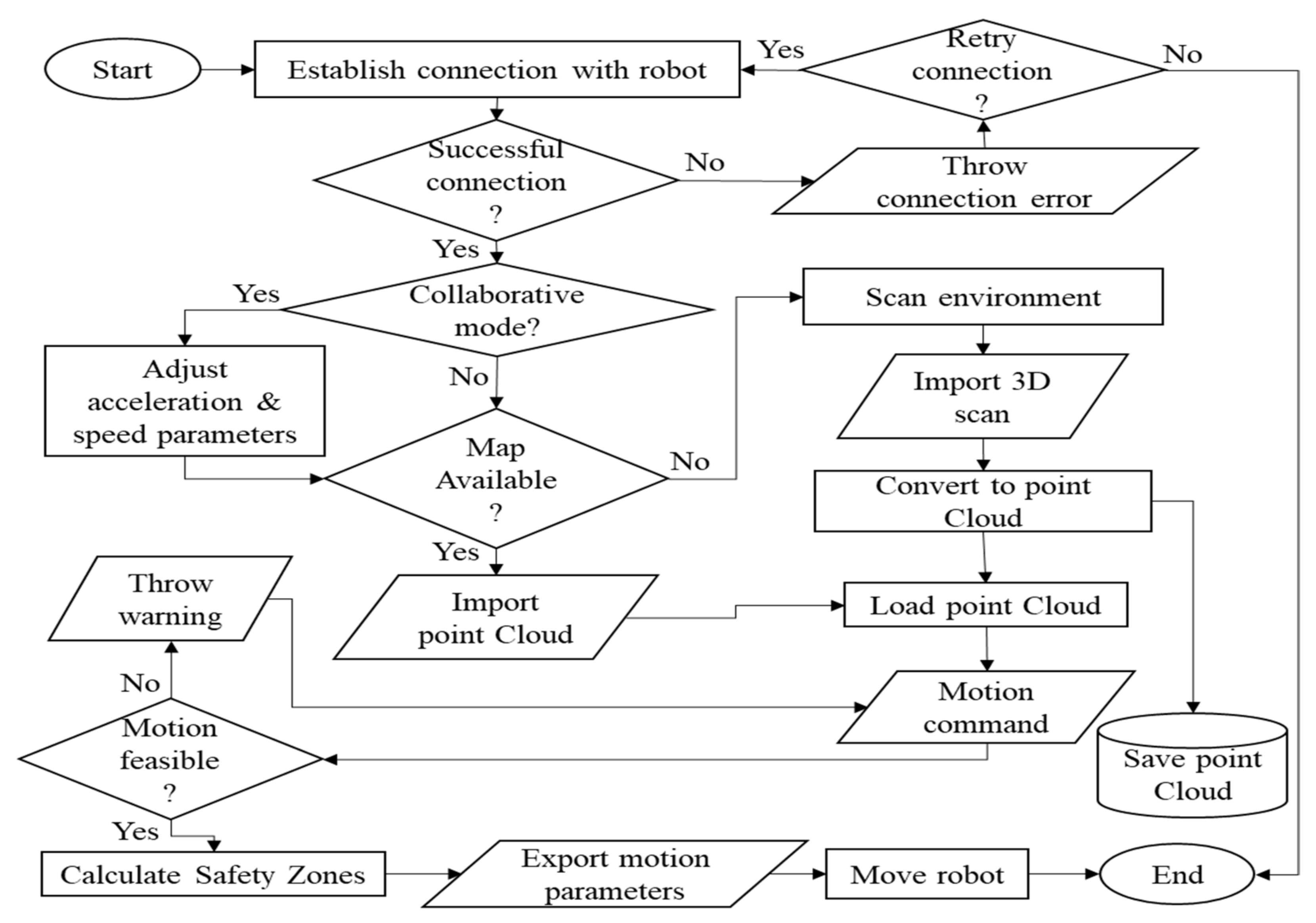
The proposed method is based on the design and development of two main software modules. The first module is responsible for the 3D representation of the robotic manipulator surroundings. The second module is responsible for the simulation of a 3D functional model of the robotic manipulator as well as the calculation of the kinematics. Essentially, the framework consists of a closed-loop control system for the robot; as the user inputs the desired position, the digital twin of the robot calculates the positions/motions of the robot joints. Then the resultant motion is sent to the robot’s controller to be executed as well as to the MR application in order to generate the visualization. Finally, the robotic controller sends feedback to the backend of the application in order to confirm that the motion has been successfully executed, and thus the user can proceed with the input of a new motion. The above-mentioned process is executed recursively until the user terminates it. In
Figure 1, the flowchart of actions, describing the proposed system architecture is presented. More specifically, the framework initially relies on the successful connection of the AR/MR application with the interface of the robotic arm. As soon as the connection has been established and no errors are thrown, then the user selects whether they wish to work with a collaborative robot or just manipulate the robot. In the case of the collaborative mode, safety precautions are automatically applied, such as the maximum velocity and acceleration of the robot, as per the ISO/TS 15066, which explicitly specifies the requirements for collaborative robotic cells.
Then, the first functional block for the manipulation of the robot is the environmental understanding by the computer(s). This task can be accomplished in two modes. The first mode requires a 3D map of the environment of the robotic arm, so the resultant 3D map in the form of a point cloud is imported into the development environment.
3.1. Robotic Arm Navigation Module
One of the main features of the navigation framework is the visualization of the robotic arm’s reachability, i.e., the maximum distance the end effector can reach. Concretely, during the navigation of the robot with the use of the navigation tool, the user receives a vivid visualization of the robot’s reachability. This is accomplished either statically or dynamically. The static mode involves the visualization of color-coded reachability zones. Therefore, the areas located close to the base of the robot are colored green, indicating a close-range radius and minor loss in capacity. Similarly, medium range areas are colored yellow, indicating also that the robotic arm’s capacity is significantly reduced, and with orange the limit/high radius is displayed. Finally, if by mistake the user tries to guide the robotic arm in an unreachable area, this area is colored red, and an error notification is displayed in the graphical user interface (GUI).
3.2. Virtual Robot Animation
The second mode of the reachability visualization is based on the animation of the 3D robotic arm. Therefore, as the user commands the 3D robotic arm to move in a specific place, i.e., point to the 3D point cloud, the robotic arm is colored based on the color codes discussed in the previous paragraphs. Further to that, if the user instructs the robotic arm to move towards a position, which is obstructed by a foreign object, then the robotic arm is colored red and a notification pops up in order to notify the operator in a timely manner. In addition to that, the robot motion is halted until a new command is given by the operator. It must be noted that this functionality also takes into consideration the limitations of the robotic arm motors.
As will be discussed in the following paragraphs, the robotic arm used cannot perform a full circle rotation, i.e., a 360-degree rotation, for any of the comprising motors. Consequently, if the motion exceeds this limitation, then the motor brakes are automatically engaged in order to protect the motors and the robotic arm itself. This is a stressful and time-consuming situation, as the operator has to manually reset the robotic arm to a safe position. The framework, however, does not let such a situation arise, as it gives timely notification to the user to re-design the robotic arm motions.
An equally important feature implemented is the automatic generation of safety zones and their continuous visualization around the robotic arm with respect to the next motions to be performed. Again, the robotic arm in the current experimental setup has already been implemented with all the required safety protocols regarding the operation of the robotic arm in a collaborative environment as per the guidelines provided by ISO/TS 15066. The framework automatically applies these regulations when the user is prompted to select whether the robotic arm will collaborate with a human operator or not. Consequently, the margin of error is further minimized as the speed and acceleration settings for the robotic arm motors cannot be exceeded and most importantly cannot be overridden.
However, in industrial robots this is not a standard feature; therefore, it is of great importance to notify the shop-floor operators in a timely manner about the robot’s intentions. As a result, while using the framework, the safety zones of the robot are automatically created and can be later communicated to the shop-floor operator wirelessly in the form of 3D visualizations. Since the robotic arm is moving in all three directions, the safety zones are implemented as 3D objects, thus contributing to a more intuitive user experience.
3.3. Augmented Reality via Handheld Devices
As will be discussed in the next section, the proposed system architecture can be realized through the development of a multi-platform MR application. The implementation of the application in handheld devices is supported, as these devices are widely adopted and no special equipment is required. However, since the handheld devices, i.e., tablets and mobile phones, have very limited hardware and software capabilities in contrast to HMDs, certain functionalities cannot be implemented in the mobile version of the application, while others are tailored to fit the capabilities of these devices.
3.4. Mixed Reality via HMDs
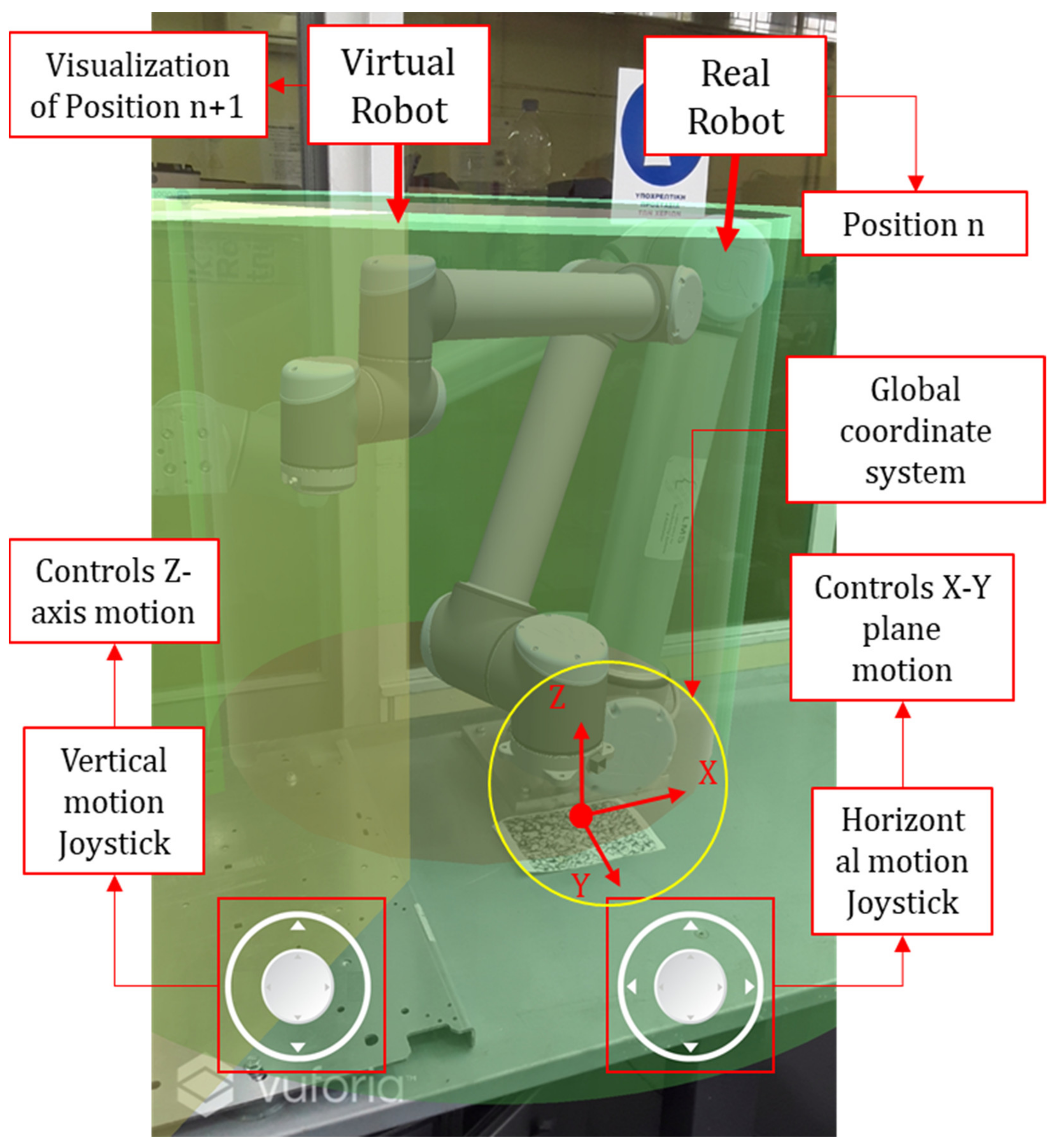
The proposed system architecture will encompass the complete list of functionalities in HMDs, such as the Microsoft HoloLens MR device. In addition to that, the implementation in such devices comes in the form of Mixed Reality, since the users will interact with the holograms registered in their real environment for the manipulation of the robotic arm. When the application is used in conjunction with an HMD, i.e., Microsoft Hololens, the user is able to drag the robotic arm via the use of a pinch gesture. In this mode, the user can position the virtual robotic arm to the desired position, make adjustments to the end effector pose, and as a result teach the new position/pose coordinates to the robot.
3.5. Safety Zone Visualization Module
Human safety in industrial environments, particularly when collaborative robots are involved, is of paramount importance. As a result, the proposed method has been designed to calculate and display safety zones whenever a shop-floor technician works near a collaborative robot. The following equation is used to calculate the safety radius (ISO/TS 15066):
where K
R denotes robot speed, K
H denotes human operator speed, T
R denotes robot reaction time, and T
B denotes robot breaking time. The UR10 robot has a reaction time of 400 milliseconds and a breaking time of 1250 milliseconds, as well as a maximum end effector speed of 120 degrees per second and a maximum braking distance of 56 degrees.
4. Software Tool Implementation
For the implementation of the proposed framework, a multi-platform, stand-alone application has been designed and developed. The application is compatible with handheld devices, such as tablets and Head-Mounted Displays (HMDs). However, it is stressed that the 3D scanning of the robotic arm surroundings is capable only for the HoloLens HMD due to the limitations of the handheld devices’ hardware. Concretely, the HMD chosen is the commonly known Microsoft HoloLens MR HMD. As far as the handheld device is concerned, a common Android tablet has been chosen.
Regarding the development of the framework, the software used was mainly the Unity 3D game engine, due to the wide range of MR functionalities and supporting APIs. In addition to that the Vuforia API was used for the development of the functionalities of the handheld-based MR, whereas the Mixed Reality Toolkit (MRTK) was used for the HMD based MR. The writing of the code scripts was accomplished in C# programming language, using the Microsoft Visual Studio IDE.
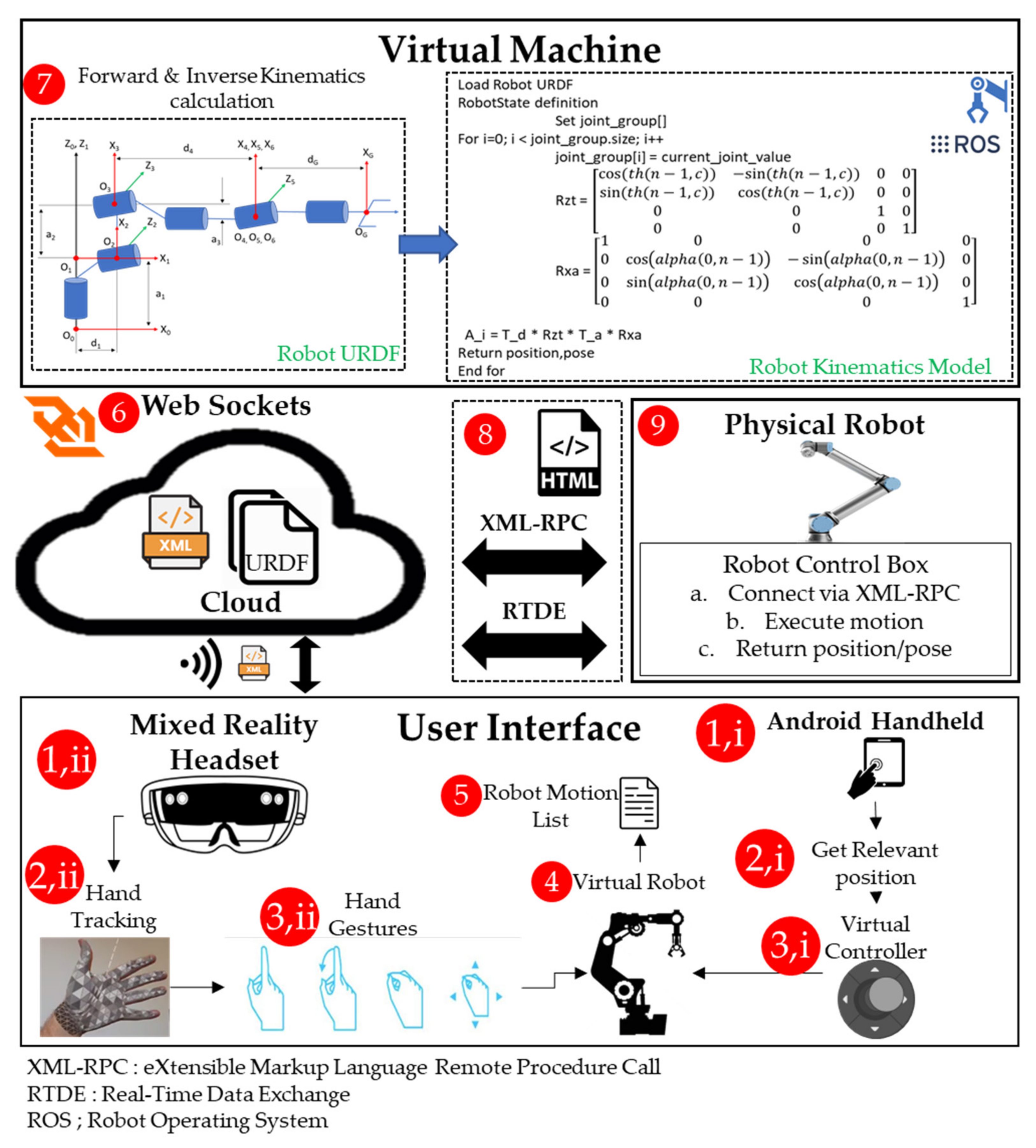
One of the most important implementation steps is the communication of the framework with the real robot, and more specifically the robotic arm’s controller. As discussed in the previous paragraphs, the main goal was set to develop a fully wireless framework. As such, for the real-time data exchange the TCP/IP protocol was implemented, which is also compatible with the UR10 interface. The communication with the robotic arm is performed in two layers. The first layer is the real time data exchange layer and its purpose is to transmit data from the robot to the backend of the developed application, so that the position and the status of the robotic arm is successfully perceived by the application and, by extension, the 3D model is updated. The second layer of communication is the remote procedure call. This method can be realized as an XML file exchange between the application and the robotic arm controller, enabling the communication of programs, i.e., motion commands and methods/function calls, from the application, i.e., the user, to the robot. The architecture of the communication interfaces, based on the UR10 implementation, is presented in
Figure 2, emphasizing the steps involved (see steps 1–9), the information flow (see the data filetypes), and the communication protocols implemented in order to achieve the interface between the individual modules. Below the step sequence is presented:
START
Step 1: Launch application on
Step 2: Environmental understanding based on the device sensing system
Step 3: Control virtual robot via
Virtual controllers, implemented on the application GUI
Hand gestures (e.g., tap to select, tap hold to grab, drag while grabbing)
Step 4: Update visualization of the 3D robot on the real environment
Step 5: Save current position
GoTo Step 3 for new motion OR GoTo Step 6
Step 6: Upload motion list (XML file) to Cloud Database
Step 7: Digital twin of robot (ROS environment)
Initialize communication with Cloud Database via web sockets
Download list of motions, and robot’s URDF (Unified Robot Description Format)
Calculate the kinematic values
Check feasibility of motions list
Step 8: Setup communication framework with physical robot
Step 9: Motion execution in physical robot
GoTo Step 3 until user interruption
END
Furthermore, for the facilitation of communication between the robotic arm and the standalone application, the Robot Operating System (ROS) acts as a middleware for the translation of the 3D motions into commands for the actual robot. The ROS is utilized since it provides advanced capabilities regarding the calculation of the robotic arm kinematics and reverse kinematics. More specifically, what is of great interest is the calculation of the robot’s joints revolution angles. These values, along with the other information, such as the robot’s physical properties, are saved in a separate file, also known as Unified Robot Description Format (URDF). However, in order to enable this functionality in the Unity 3D development environment, the Rosbridge API has been implemented. It is stressed that from the standalone application, every time the operator moves the 3D robotic arm, for every joint of the robot, the angular displacement is recorded in a JSON file. Concretely, for the ROS operating system, a virtual PC has been set up and the motions from the standalone application are imported in the form of a JSON file, then the ROS engine interprets the motions in robot commands with the utilization of inverse kinematics for the corresponding robotic arm which are then communicated to the robot’s control box via web sockets.
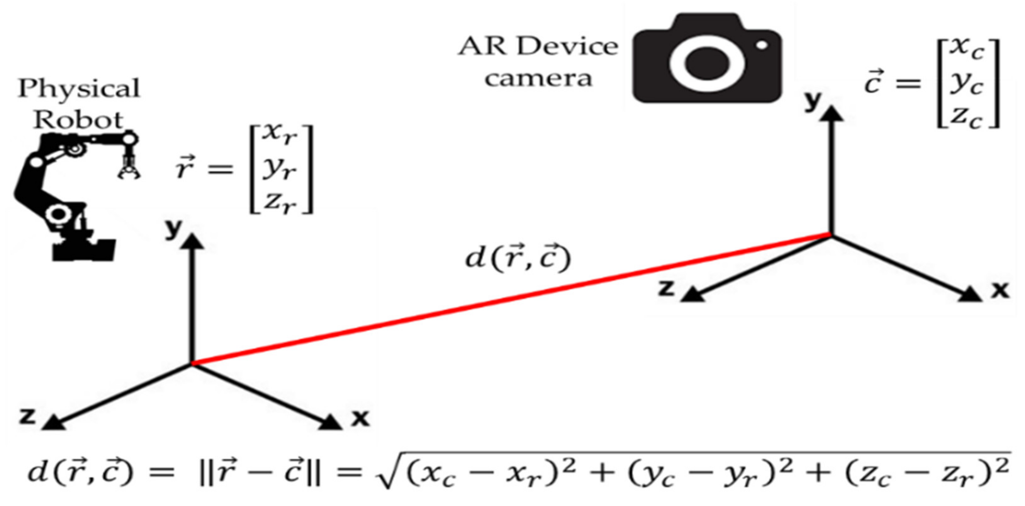
In an attempt to further raise the awareness of the technicians whenever they work in close collaboration with the robot, two functionalities have been developed. The first functionality is the distance indicator, which calculates the absolute distance between the user (camera position) and the base of the robot, and is expressed in meters. In the following figure (i.e.,
Figure 3), the distance calculation method is illustrated. The equation (Equation (2)) presented in
Figure 3 is a basic vector equation for the calculation of the relative distance between two vectors. In this case, the two vectors are the relative coordinates of the device and the base of the physical robot. In order to set up a global coordinate system, the setup of a 3D (virtual) anchor is required for indicating the origin of the virtual and physical environment (0,0,0). However, as per a reviewer’s comment, we have further elaborated the content of
Figure 3 in order to explicitly illustrate/indicate the above-mentioned technical information. Furthermore, the equation has been introduced and discussed within the main text of the manuscript.
where
is the absolute distance between the user (device camera) and the physical robot, in meters.
are the coordinates of the robot’s base.
are the coordinates of the device camera.
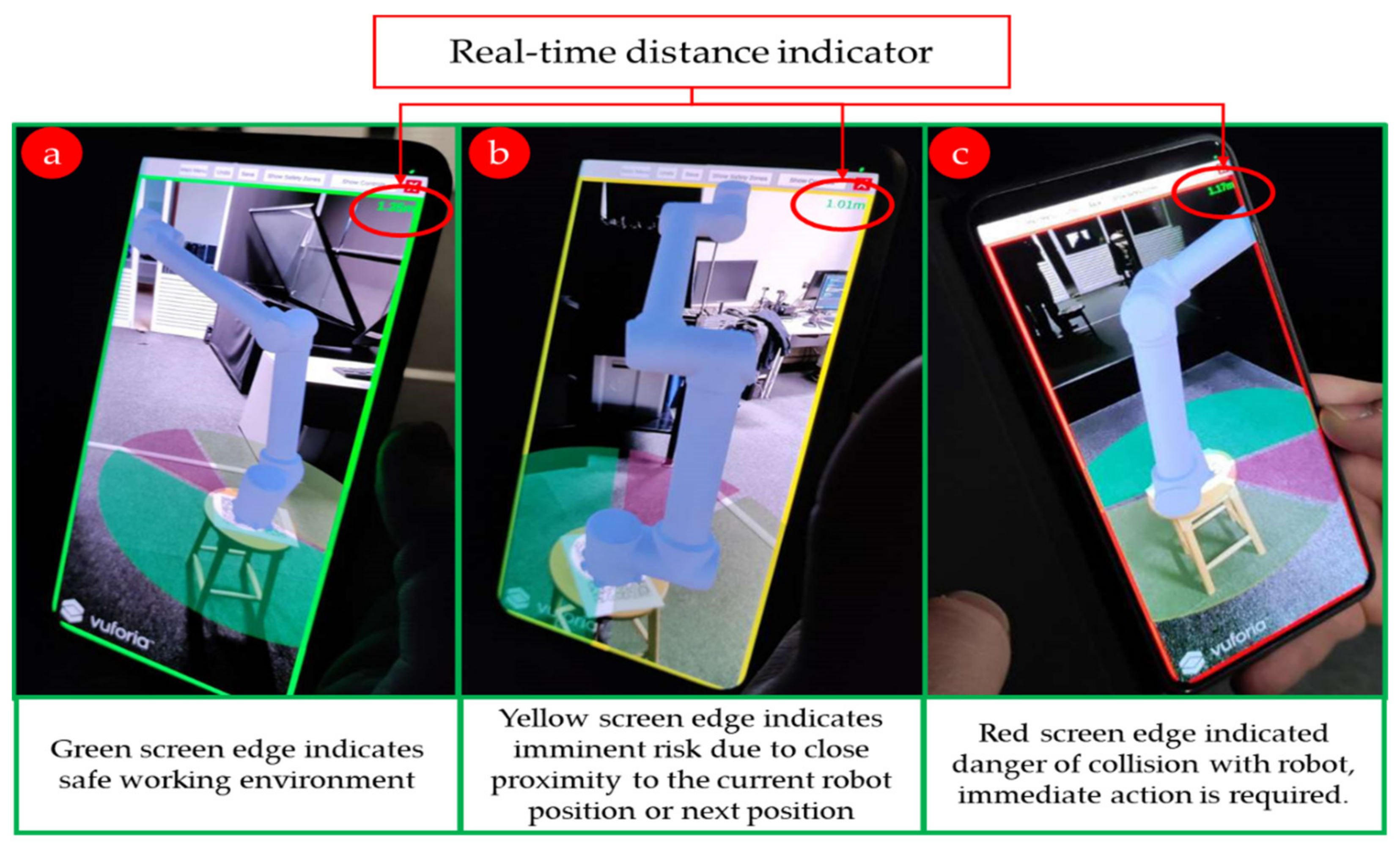
The second functionality is the display of a colored edge around the screen of the user’s device. The color-coding for this functionality is based on the color coding of the safety zones. In
Figure 4 the three states are indicated as the user’s position in relation to the robot changes.
The current implementation of the proposed framework is based on the development of a mobile application which is compatible with Android-based handheld devices. The developed application currently contains all the needed functionalities for the robotic arm manipulation, which include the main functionality, the communication of the application with the control box of the robot as well as the near real-time data exchange, which is used for the visualization of the robot’s current position and stance. The main HoloLens application has also been developed, however, during the development of the framework, and issues have arisen regarding the communication of the 3D map to the framework so that the dynamic safety zones can be implemented. More specifically, the issue concerns the spatial scanning of the environment of the human operator which, by extension, contains the robotic arm. Therefore, what is needed is the development of an extra module for the recognition of the robot geometry by the HMD and the dynamic exclusion of the polygons, representing the figure of the robot, from the spatial map created by the HMD. As far as the safety zones are concerned, in the current development, they are implemented as 3D cylindrical objects covering the volume of the robot itself and its close surroundings. More specifically, there is an area close to the robot, which is constantly prohibited, thus it is coloured red, and an outer area in which the user can freely move shown as green. A partial cylindrical area of 30 degrees around the end effector indicates the intentions of the robotic manipulator. A representation of the current developments is depicted in
Figure 5.
From a hardware point of view, the development and testing of the application, a desktop PC equipped with an Intel Core i7 CPU, 16GB of RAM memory, and a Nvidia 1060 GPU has been utilized. In
Figure 5, the virtual robot is illustrated in AR. More specifically, in this figure the key functionalities of the developed application are presented, such as the virtual model of the robot, the safety zones, and a real-time distance indicator.
5. Case Study
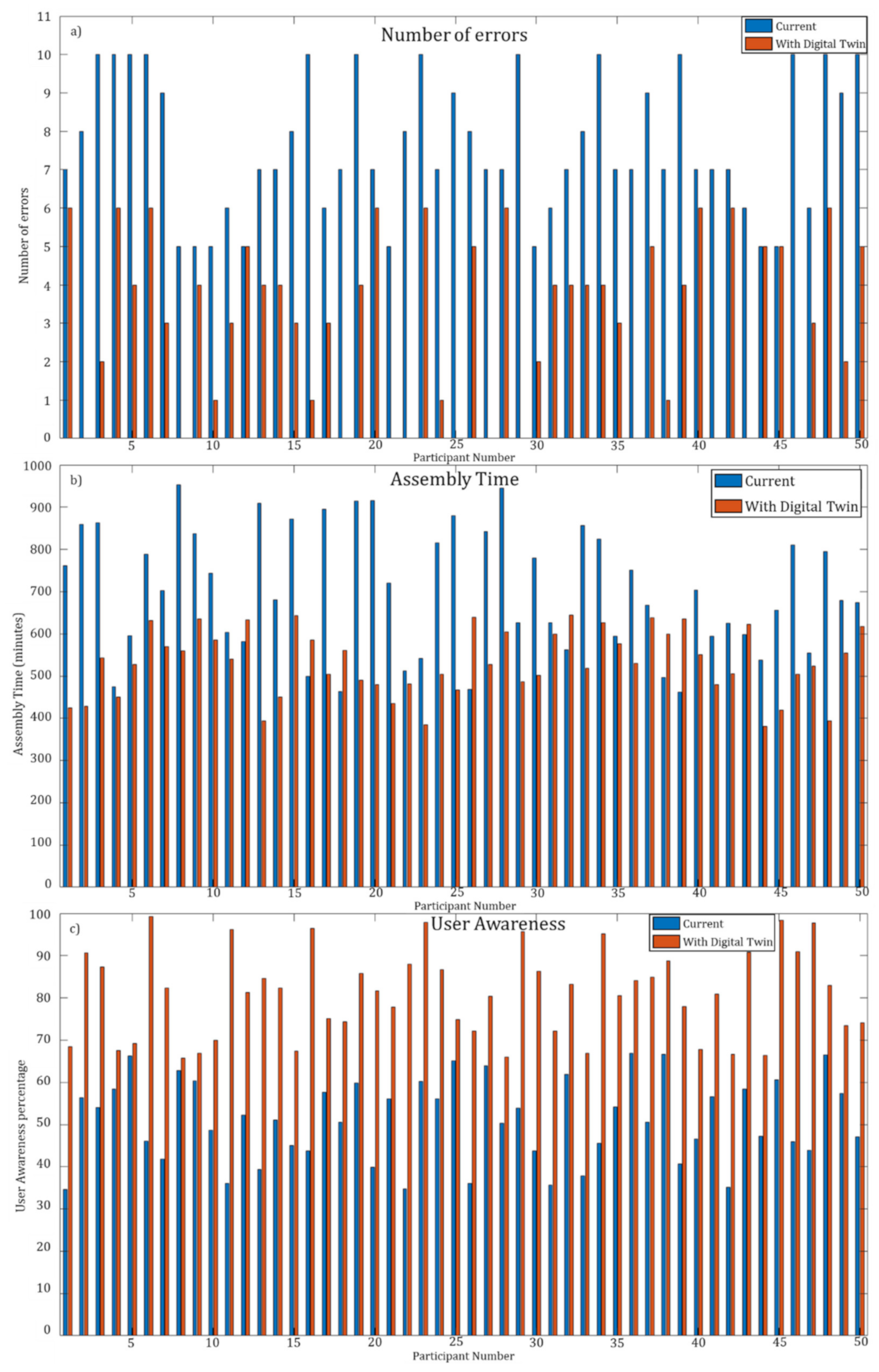
For the validation of the developed robotic arm navigation tool, a set of experiments has been set up in a laboratory-based machine shop. More specifically, a UR10 collaborative robot has been used which is installed in the machine shop. It is stressed that there has also been developed an additional functionality in order to enable users to create different configurations of the robotic arm and its surroundings which has facilitated experimentation with different configurations. Initially, the testing was focused on the 3D scanning of the robotic arm surroundings and, more importantly, on the 3D regeneration of the 3D map by the framework. Upon completion of this step, either the engineer or the shop-floor technician is able to navigate the robotic arm remotely from the provided AR-based GUI. In the experimental tests of the framework, five engineers and shop-floor technicians participated. Each of the participants had to perform a set of actions in two different situations, i.e., the current situation, involving the hardwired robotic controller and the developed wireless application. In each of the experiments, the number of errors was measured, as was the user’s awareness, the ease of use, and the time needed for completion of the assigned tasks. An error is defined as an action that leads to conflict between the human operator and the robot and also as a robot motion that leads to conflict between the robot and any other object in its surroundings. It is stressed that the experiments were conducted with the use of the UR10 robotic arm, which is considered to be collaborative, and upon collision the robot motion was automatically halted. Thus, no health risk was induced during the experiments. In order to record user awareness and ease of use, a short interview with the participants was performed after the end of the experiments. Finally, the whole process was recorded for each individual, including the number of errors and the total time needed for each experiment to reach completion.
Six metrics have been used in evaluating HMI: (1) Task effectiveness, (2) Neglect Tolerance, (3) Robot Attention Demand, (4) Free Time, (5) Fan Out, and (6) Interaction Effort, on a scale of 1 to 10. A short description of each metric is presented in
Table 2 [
38]:
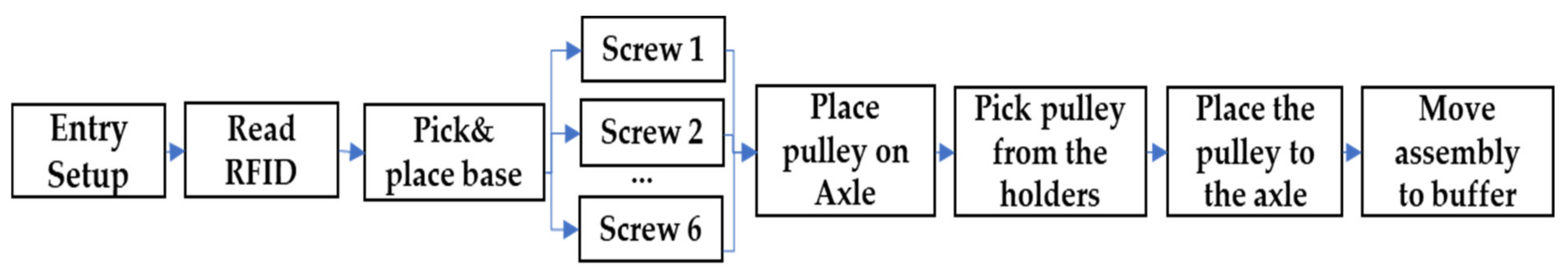
As far as the experiment scenarios are concerned, two different scenarios have been tested. In the first scenario, the operator had to work in collaboration with the robotic arm in order to assemble a mechanism. The assembly process involved the collection of the assembly components by the robotic arm and their placement on the assembly, while the operator had to secure the assembled components with screws. It is stressed that during the execution of this scenario the participants selected a set of predefined movement sequences from the GUI of the developed application. Such movement sequences were pre-created by the engineering department and uploaded on a Cloud database which served as a repository for such assembly scenarios. However, through the GUI of the application, the shop-floor engineer could alter the parameters of the movement sequence so that the collaboration between the human and the robotic arm was further facilitated, considering the safety limitations. For the second scenario, the operator had to transfer high-volume objects with the use of the robotic arm under low visibility circumstances. In
Figure 6, the assembly sequence, in the form of steps, is presented.


