1. Introduction
The main aim of this paper is to develop a new methodological basis for designing a workplace using Virtual reality (VR) and motion capture (MoCap) to assess operator working positions in manufacturing. The proposed method should be mainly used in industry during preproduction phases or for the innovation of a current manufacturing system (e.g., the change or modification of a current workplace). This could lead to economic benefits. The methodological basis (method) is then validated using more on-site experiments. There are many legal regulations and standards for workers that specify the limits of physical stress that should be observed during a work shift, but the use of disruptive technologies is not regulated.
In today’s era of widespread robotisation, it may seem that the role of humans in production is becoming irrelevant, but the opposite is true. Humans will never disappear from the work process completely but will occupy different jobs than before [
1]. Today, there are many laws, standards, and regulations that protect workers from overexertion, whether it is chemical, biological, or physical.
The overloading of workers and the possible development of musculoskeletal disorders and possible occupational diseases is a major problem nowadays. Occupational diseases are conditions or disorders that arise from the character of the job. The most frequent occupational diseases are musculoskeletal disorders. Musculoskeletal disorders (MSDs) are injuries or disorders of muscles, nerves, tendons, joints, and spinal discs. They affect millions of workers across Europe [
2] and are a serious problem, accounting for 33% of all occupational injuries and illnesses that require days away from work. Addressing this issue not only helps improve the lives of workers but also makes business sense [
3,
4]. Research [
5] shows that almost two-thirds of EU workers say they do work that requires repetitive upper limb movements. A quarter of workers also report being exposed to vibration from work tools. These two risk factors are the most important factors leading to work-related neck and upper limb disorders (also referred to as WRULDs). These disorders affect many workers in a variety of occupations and are the most common type of occupational disease in Europe, accounting for more than 45% of occupational diseases. The issue of occupational diseases or musculoskeletal disorders is undoubtedly an important topic that affects not only the workers themselves but also the economy of an entire company [
6]. The prevalence of occupational diseases, which include occupational diseases and occupational hazards, is an important indicator of the health status of a country’s population and working conditions, as reported by [
7]. The assessment of the health status of working citizens is approached differently in each country, as stated in [
8].
In the Czech Republic, for example, a total of 1282 occupational diseases were reported in 2018 among 1034 workers, of which 1222 were occupational diseases and 60 were non-occupational diseases. In the European Union, there were increases in two occupational diseases between 2013 and 2018: other enthesopathies (inflamed and painful joints; up 12%) and upper limb mononeuropathies (conditions affecting one peripheral nerve of the hand, e.g., carpal tunnel syndrome; up 13%) [
9]. Physical factors are the most common reason for occupational diseases, leading to the most common occupational diseases—upper limb disorders, especially carpal tunnel syndrome [
2,
10]. Industrial companies need to think about the workplaces in which operators work; for this reason, the workplace should already be ergonomically designed in the pre-production phase. The main reason and motivation for addressing this topic from a practical point of view is the high cost of design and construction work, especially when developing and producing a prototype of a machine or equipment. The high cost of ra tionalisation can be reduced by using modern tools such as virtual reality, which can almost 1:1 visualise the necessary elements of a workplace. The use of VR and the MoCap system is also discussed in [
11], which compares which types of MoCap systems in combination with VR and ergonomics have already been used.
A virtual model can be worked with by displaying it on a computer monitor, for example. Modern disruptive technologies mean that such a model can be controlled using virtual reality tools. In the context of design and project solutions, virtual reality technologies can be used in several phases of the product life cycle. Particularly in the preparatory stages of projects, industry is trying to reduce the time and, therefore, the financial requirements in the stages of research, development, testing, and production of a technical object.
Another costly part of a project is the prototyping phase, where virtual reality technology offers great opportunities for application, both in the prototyping phase and in the simulation and testing phase of the prototype [
10]. In order to verify workplace ergonomics virtually, it is not enough to use virtual reality but to combine two technologies—VR and MoCap. In particular, the use of modern technology such as motion capture using a kinematic suit that captures the movements of individual parts of the human body seems appropriate [
11].
Let us have a look at the current state of the data collection methods in ergonomic studies. Just a few studies [
11,
12,
13,
14,
15,
16,
17,
18] integrate these physiological measurements with biomechanical analysis tools. However, these approaches interfere with the work to some extent and require the subject to physically imitate the task prior to the analysis. Collecting the data for assessing the physical demands and ergonomic posture currently depends on this direct observation. Although direct physiological measurement (using goniometers, force sensors, accelerometers, electromyography, and optimal markers) offers a high level of accuracy and provides information that is more objective, it may be limited by experimental cost, environment, and technical and ethical issues for both non-invasive and invasive approaches [
18,
19]. The risk assessment tools, including REBA, RULA, 3D Static Strength Prediction Program (3DSSPP) [
20], etc., require detailed physical data, such as joint angle, for complete human body motion analysis. These risk assessment tools have not been fully implemented in design cases because of the limitations with respect to physiological measurement. Joint angle and body posture can be obtained not only by direct measurement, but also by indirect measurement (e.g., Kinect range camera, computer vision–based approaches). Refs. [
21,
22,
23,
24,
25,
26,
27,
28] review the current limitations of implementing computer vision reftechniques and suggest potential areas for future applications. The next step to assessing ergonomics in the workplace is using 3D modelling of the workplace and capturing the worker’s movements using a motion capture suit, which is used by [
29] or [
30].
Other authors address traditional workplace ergonomics assessments, such as real-world measurements of workers, or the use of standardised questionnaires [
14,
15,
31].
However, the assessment of working postures is not the only thing that a technologist in collaboration with an ergonomist should be concerned with. An integral part of workplace design is also the assessment of local muscle loading which is normally only assessed in the real workplace. Local muscle loading should be assessed in the pre-production phase, especially as unilateral and repetitive loading is one of the biggest risk factors for operators in production. This issue is addressed in [
2,
5], whose research focuses on the effect of upper limb position on local muscle loading of the forearm.
Nowadays, many larger companies (especially automotive and aerospace companies) are already using the possibility of linking virtual reality and motion capture and their real-time evaluation by means of motion capture (MoCap) in order to streamline pre-production phases in particular [
32]. However, these activities are carried out intuitively and optimised on the basis of internal know-how. Ergonomic field validation in the context of a combination of VR and MoCap has several advantages (as outlined above). In particular, there is no need to build a physical prototype of the workplace or to test everything in live operation. MoCap has the benefit of being able to perform a high number of measurements in a short period of time, resulting in higher possibilities of optimising the ergonomic design of a (perhaps not yet existing) workplace. A complete description of the possibilities of using the MoCap system is described in more detail in [
33], where the author describes, in particular, all the possibilities of using these systems. Defining the term virtual reality can be relatively subjective. The possibilities of describing virtual reality and its further use in ergonomics are described in [
11,
34], where the authors describe the use of virtual reality for ergonomics. Among the general advantages of using VR applied here are the possibilities of standardising the environment, the easy replicability of the experiment, and the ease of performing and preserving the experiment record.
So, the initial research question is this:
To answer this question, we will first set a method and a pilot validation study. We first need to set some constraints:
It is likely that neither of these constraints is a limiting factor, but this will not be the focus of this paper (but it will be dealt with in a follow-up paper).
We need to select a representative workplace to describe the software used and developed for solving the research question.
2. Reference Workplace for Validation
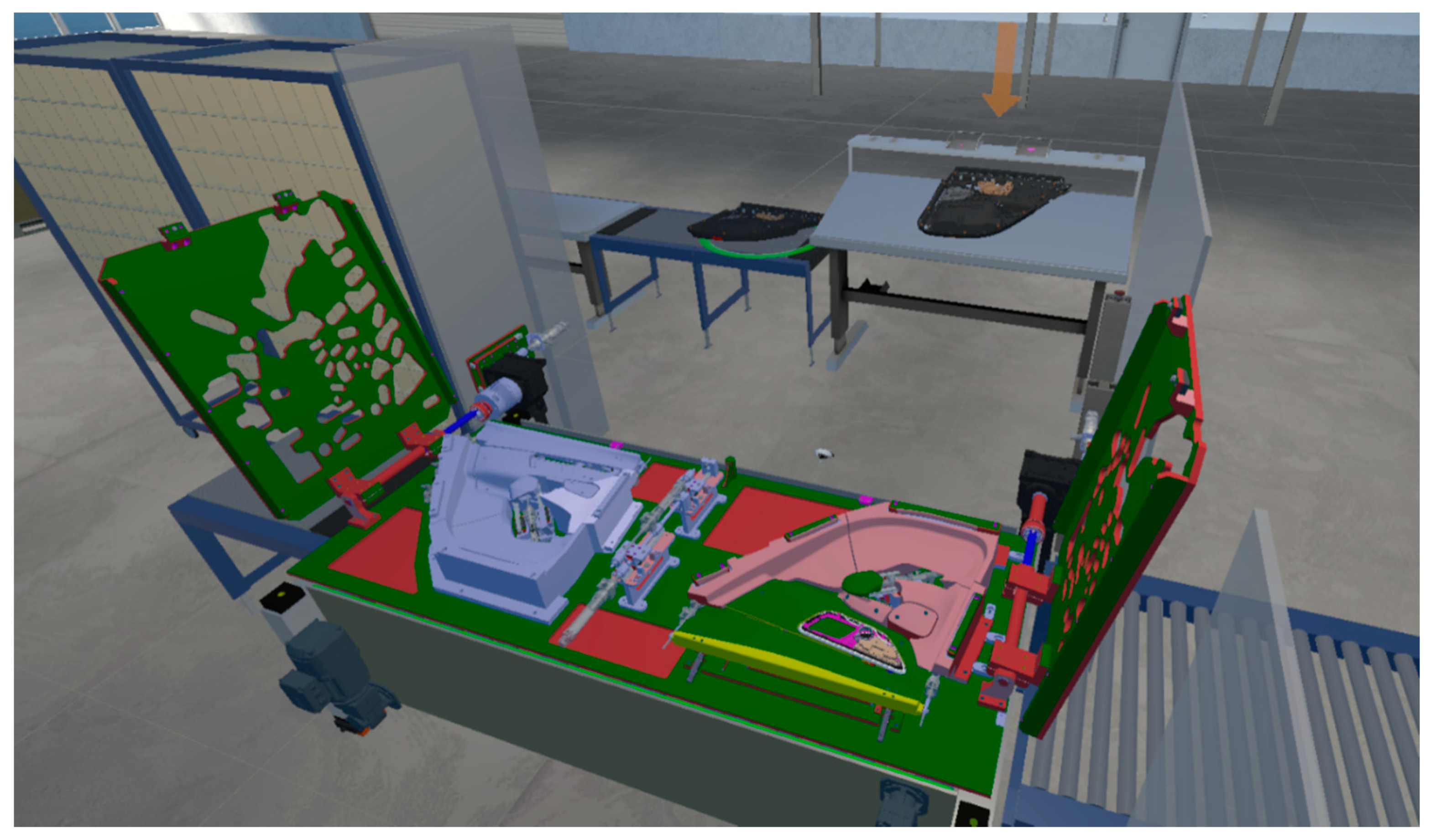
For validation and study of the pilot method, we chose a standardised workplace of an assembly line for the production of door parts in the automotive industry (
Figure 1). This workplace was selected by the expert group from an ergonomic point of view. CAD data and workflow were provided for the workstation and is given below. The description also includes a time standard.
The working procedure for the workplace:
The work is performed standing up, with occasional walking.
The worker grasps the part with both upper limbs, carries it to the workbench and places it in the jig (standard time 10 s).
The worker then uses their right upper limb to remove the first part from the KLT box (80 mm × 80 mm, weight 1.5 kg), which is placed on a shelf behind the workbench. They place the part in a predefined place according to the instructions (standard time 13 s).
Then, again with the right upper limb, they remove the second part (small part 10 mm × 10 mm, weight 3 g) which is on the left part of the shelf. They place the part again according to the instructions (standard time 15 s).
After placing the parts, the worker presses the control button, which is on the right side of the workbench (standard time 2 s).
The worker then removes the entire part (1200 mm × 1000 mm, weight 8 kg) and moves it to the work line, which is behind the worker’s back (standard time 10 s).
They then remove the trolley rail with their right upper limb and then place it in the stack of completed parts on the production line (standard time 8 s).
The final step is to confirmed using the save button—the final-part departure button (standard time 2 s).
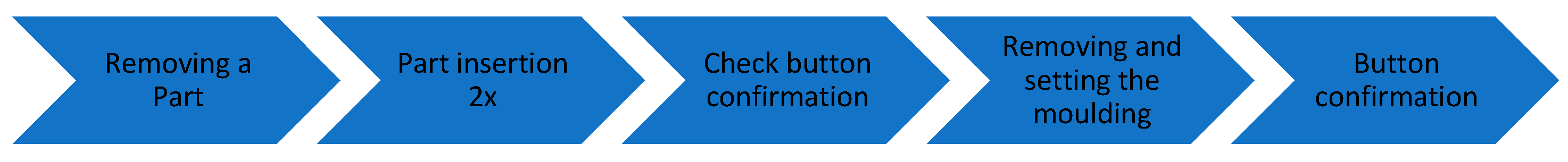
This process is repeated throughout the production shift. The shift lasts 450 min, with both women and men working on the job. The production standard is 450 pieces/shift. A diagram of the workflow is shown in
Figure 2.
3. Description of Hardware and Software
The hardware used for this study is divided into two parts: the hardware for the virtual reality and the hardware for motion capture technology. Virtual reality can be displayed in several ways. The most widely used option is an HMD (Head Mounted Display) [
23]. The user is completely immersed in the virtual world, which helps them to comprehensively understand the projected situation. The HMD used in this study was the Oculus Quest 2. This is a standalone device (no additional hardware is required) that uses inside-out tracking; cameras placed on the front of the goggles track the controllers/hands and the surrounding environment, which can transmit to the virtual environment. At full load it can be used for 2 to 3 h. This device was chosen mainly because of its high mobility and display quality. The controllers can be used to provide feedback to the user by vibrations that the user feels, for example, when colliding with other objects.
The MoCap suit Perception Neuron Studio from Noitom was used for the ergonomic evaluation. This type of suit for recording MoCap data was chosen mainly due to its ease of deployment for the user, customer support, and lower cost compared to its competitors. Gloves can be used with the suit to precisely track individual fingers. Perception Neuron Gloves were replaced by Oculus Touch controllers, primarily due to the ability to provide feedback to the user. The Perception Neuron suit consists of seventeen inertial measurement units (IMUs), and each sensor is composed of a three-axis accelerometer, three-axis gyroscope, and three-axis magnetometer that sense individual body parts. The sensors are mounted on flexible strips at precisely defined positions. The individual sensors send signals to the Axis Studio software (Noitom), which displays them on an animated avatar. The suits collected motion data at a 90 Hz sampling frequency. The recorded animations can be played back and exported.
The Unity3D game engine was chosen to evaluate the recorded movements. Unity is a multiplatform game engine developed by Unity Technologies. It is primarily used for developing computer games for PCs, consoles, mobiles, and the web. Unity3D has also proven to be a reliable way to solve many practical and scientific problems, such as [
33,
35]. Unity is a complete software application for creating 3D or 2D environments, creating animations, and interacting with models. It provides cross-platform connectivity with Windows, IOS, WebGL and, thanks to the collaboration with Android Studio, Android apps. The collaboration with Android Studio is at a high level, as evidenced by the fact that in recent years this engine has focused more and more on mobile apps and VR applications. In the last few years, this SW has started to expand into sectors other than just gaming. Unity itself is very complex when it comes to working with other programs (e.g., 3DS Max, Blender, CAD software, etc.). Part of the support for official and community development is the Unity Asset Store. This is an online library of individual components and finished solutions. For our study we used the Oculus Integration and VRTK 3.3 assemblies to ensure the basic functionality of all the objects.
In order to evaluate the recorded motions, it was necessary to develop a custom application that can play back and subsequently evaluate these motions. This application evaluates the recordings that are pre-recorded using MoCap technology. The actual software solution is a de facto parser/converter that processes the raw data from the measured sensors (FBX format from Axis Studio) and evaluates them according to the set parameters corresponding to the given legislation and processes and exports them to .csv format. As large volumes of data need to be processed, we had to optimise the import and export algorithms several times during development. To ensure a higher level of user control, the measured data can be visualised, including animations.
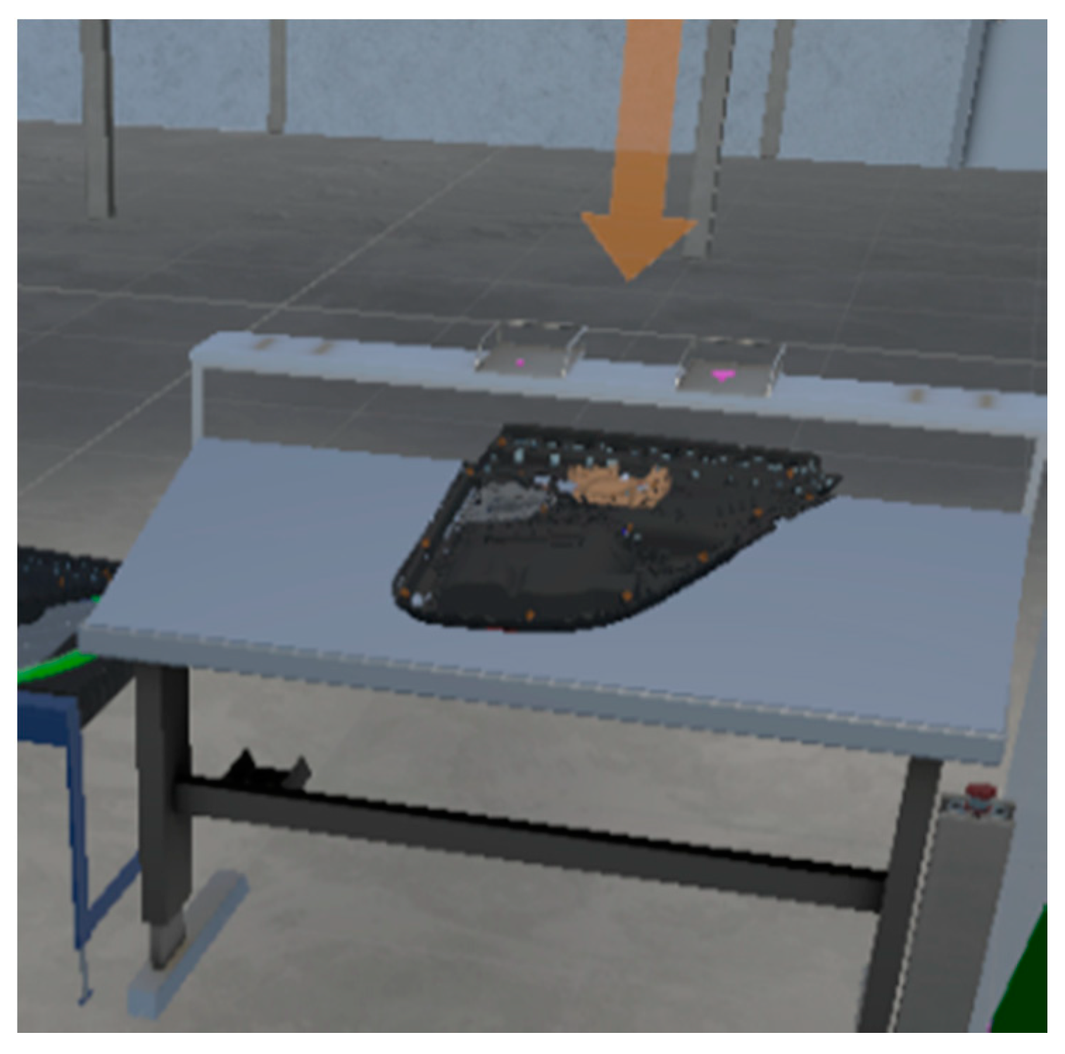
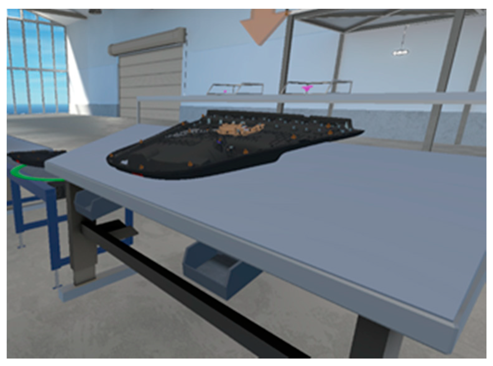
In order to display the entire workplace in a standalone Oculus Quest device, adjustments had to be made to the CAD model provided by the client. These modifications were mainly related to the reduction of the displayed polygons. In this respect, the biggest problem was the part of the production line in
Figure 3 and the detailed design of the assembled part. Such detail is not relevant for ergonomic measurements.
The whole application was mainly focused on functionality. Emphasis was placed on achieving the highest possible degree of immersion and thus simulating the required workflow of a real environment.
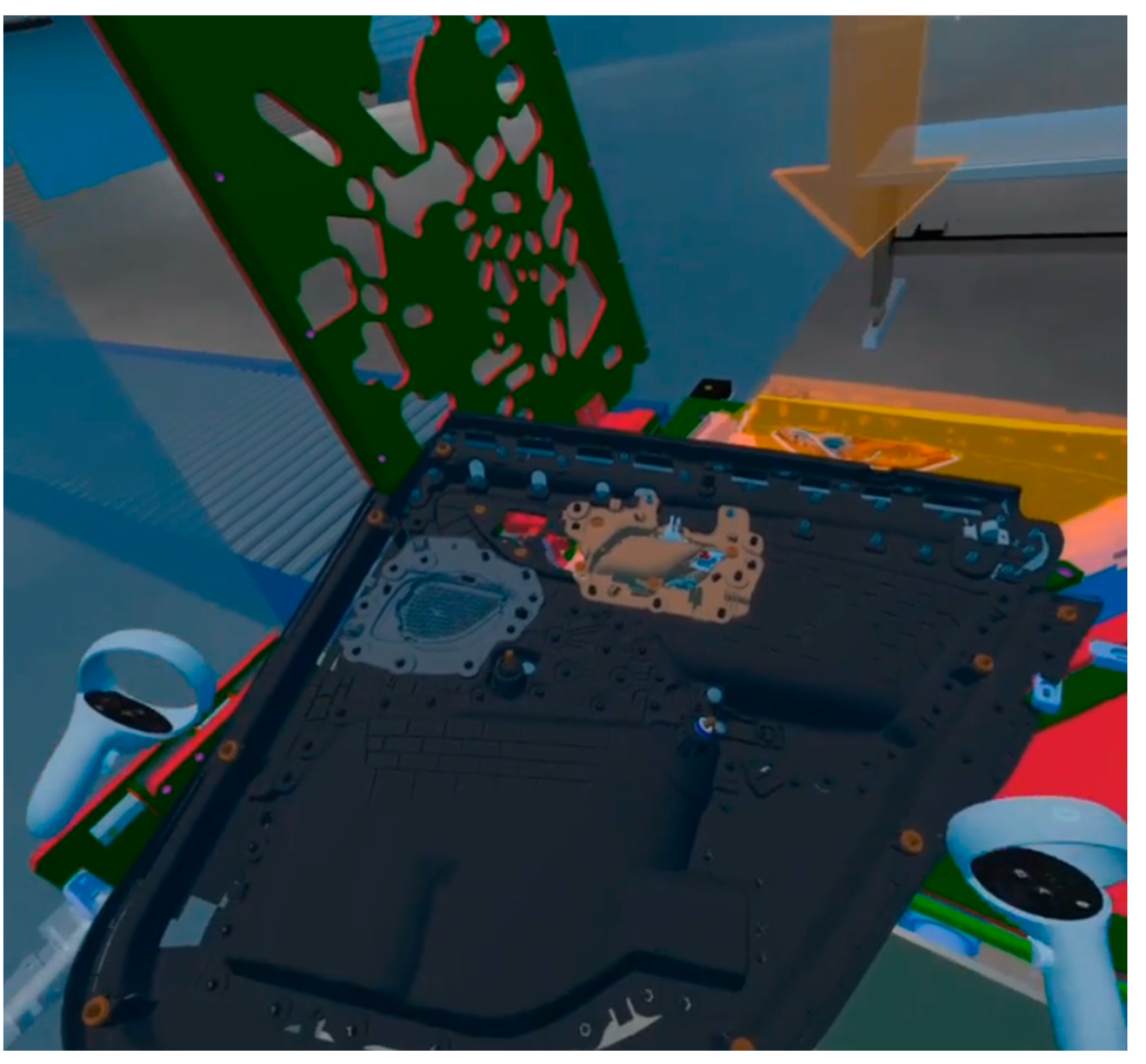
Once the workflow was defined, the modified CAD data was imported into the Unity3D environment in which the virtual reality application was created. According to the workflow, the different parts of the assembly workstation were positioned to correspond to the future realistic layout. All components were set up with the required functionality. As part of the study was to test the functionality of the designed line, the collision states during the actual handling of the parts needed to be set. If there is any contact of the part with the workstation, a visual change ("reddening") of these parts occurs. This setup means it was possible to test the handling of the parts on the workstation in the pre-production phase.
To grip the parts, the user needs to insert the controller at the designated gripping location and simultaneously press the trigger button on the controller. The application instructs the user to grasp the selected parts with both hands when required. The application was designed bearing in mind the fact that it was being used by workers who did not have any experience with VR equipment. We also assumed that the tested workers did not have any experience with this manufacturing process, so visual management features were added to the application, such as colour highlighting of the current part in the process, highlighting the part storage zone, or arrows/circles to speed up spatial orientation. The result is an app that can be run on an Oculus Quest 2 device, which can be controlled with Oculus Touch controllers to walk through the entire workflow at the selected workstation. This consists of grabbing the main door part, placing it in the jig table, where the two parts are then assembled, and pressing the confirmation button after assembly. Next, the main part moves to the line and the whole process is completed by pressing the confirmation button.
4. Methodological Basis for an Ergonomic Rationalisation
Based on the expert group method and conversations with experts, we propose a method that is straightforward, but which has still not been described in the relevant literature, probably because it requires the hardware and software resources described above.
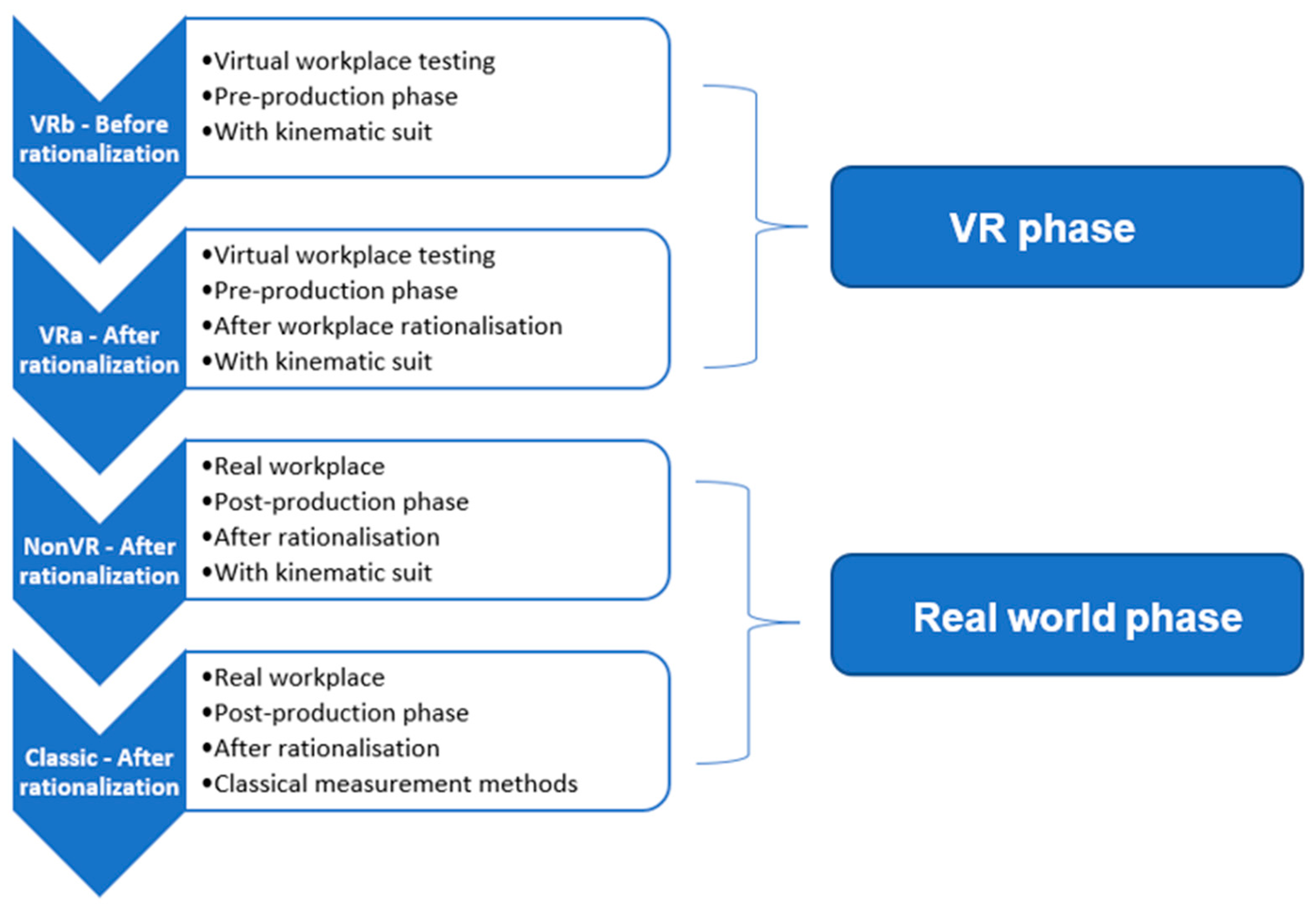
Generally, and firstly, we need to identify and select a referential workplace and identify the working procedure decomposed into operations. The measurement method itself must first be divided into two phases, which were also examined in the study (
Figure 4).
The diagram shows the four phases of the study: VRb, VRa, NonVR, and Classic which are described in more detail below.
VR phase
- ○
VRb—Measurement of working positions using the MoCap suit in a virtual environment.
- ○
VRa—Measurement of working positions using MoCap suit in a virtual environment after rationalisation.
Real world phase
- ○
NonVR—measurements using the MoCap suit in a real environment after rationalisation.
- ○
Classic—measurements using classical methods on the real environment after rationalisation.
The proposed method is piloted in an experimental study. There are some limitations of the method and also of this study:
The ergonomics of the workplace was evaluated according to the current legislation of the Czech Republic NV361 which evaluates working positions according to their acceptability as described in [
36,
37]. The method of evaluation according to the current legislation was chosen because it is more stringent than global ergonomic methods such as the RULA or REBA [
14,
38]. Therefore, any assessment carried out will be valid even within the framework of these worldwide methodologies. At the same time, the measurement is necessary for categorising the workplace in terms of physical load.
- -
This method is suitable only for an assembly workplace.
- -
Only workers with no previous VR experience are considered.
- -
Hardware—HMD (Oculus Quest 2) and MoCap suit (Perception Neuron Studio)
- -
Software—Software necessary to control the hardware, and proprietary software.
These limits can easily be broken during follow-up research and the possibilities of the method could be broadened.
The following working positions were observed and measured in all phases of the working process (VRb, VRa, NonVR, and Classic):
Head rotation greater than 15°—conditionally acceptable position.
Head tilt greater than 25°—unacceptable working position.
Torso tilt greater than 60°—unacceptable working position.
40° to 60° trunk tilt—conditionally acceptable working position.
Upper limb flexion greater than 60°—unacceptable working position.
Upper limb flexion 40° to 60°—conditionally acceptable working position.
According to the legislation: a worker may spend a cumulative 160 min in an average 8-h shift in a conditionally acceptable work position; a worker may spend a cumulative 30 min in an unacceptable work position.
Special attention should be paid to lower back pain during the evaluation. Lower back pain is a very common symptom. It occurs in high-income, middle-income, and low-income countries and all age groups from children to the elderly [
39]. Due to the type of activity performed here, where bending, stooping, or rotation of the trunk is eliminated, and the weight of the load being handled, back position and low back pain are not important risk factors. The maximum cumulative weight of loads handled is 3600 Kg per shift, which complies with working limits [
36] for men and women.
4.1. Measurement Using Kinematic Suit with VR before Rationalisation (VRb)
The study is only conducted on workers with no previous VR experience, which is also a limiting factor of this study. During the actual measurement, employees fill out a paper-based questionnaire. The purpose of the questionnaire is to find out the relevant attributes of the proband: age, gender, dominant arm, height, work engagement—the work engagement of the current work process was scored (scale 0–10, i.e., 0 = unengaged, 10 = expert), weight. While the actual outputs from this questionnaire will not be correlated, they will serve as one input for the discussion of the study results.
Immediately after completing the questionnaire, the proband is introduced to the basics of working in a virtual reality environment (such as grasping virtual objects). This familiarisation is practised first outside the VR space, so it is mainly familiarisation with the controllers, then the proband is given a short VR tutorial. This self-tutorial introduces the proband to the basics of movement in a VR environment in about 5 min. Since the measurements are performed in a laboratory area with sufficient space, the use of a so-called ‘teleport’ is not required for relocation to the workstation. Users can therefore move freely around the designed workplace within the virtual space.
Subsequently, the proband is familiarised with all the functions and manipulation of the kinematic suit parts—taking off sensors, fitting belts, turning off sensors, etc.
At the beginning of the experiment, it is always necessary to connect the encrypted dongle from the MoCap suit, as well as to connect the router using a USB cable. Then all the sensors in the box are switched on (indicated by a green flashing light). After that, the software for operating the MoCap suit—Axis Studio—needs to be switched on. A new project is created and the dimension points corresponding to the current proband are set. After that, it is necessary to check if the router is connected, the next step is to turn off the magnetic field to speed up the overall calibration. If the measurements are produced in a real environment, typically in an industrial plant where there is a possibility of high magnetic waves, this function needs to be switched on. Subsequently, it is necessary to start linking the SW to the suit, and once the linking is complete, it is possible to put the individual sensors on the proband.
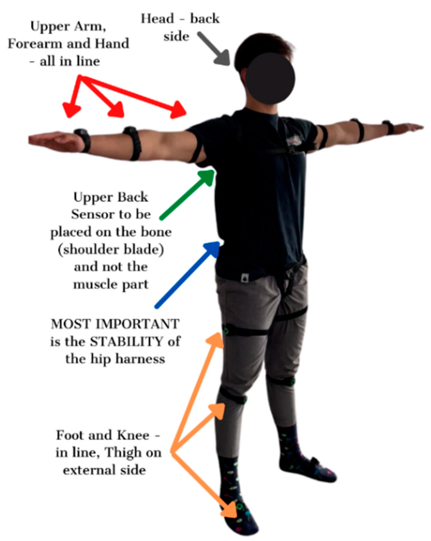
The proband is then fitted with straps by the staff which attach the sensors to the kinematic suit. The straps are placed in 17 locations, respecting certain rules which are shown in the figure below. The straps are systematically placed from the feet to the head [
40] (see
Figure 5).
The sensors are then inserted into the straps, always with the emphasis on correct seating. The suit is then calibrated. The starting position for the proband is the ‘T pose’ (abduction of both upper limbs at 90°, legs together and body erect)—
Figure 5. At this stage of the experiment, the actual measurement is not switched on.
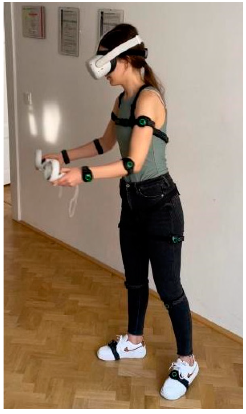
An important element is that the user should stand in the middle of the on-track area when deploying the HMD display. This area is marked out by the operating staff prior to this measurement. After putting on the glasses, the user is asked to position the glasses on their head themselves so that the image is sufficiently sharp and clear. They are also allowed to test the whole working process without any data capture. This step is particularly important so that the worker knows what the work process looks like when taking a real measurement in order to minimise measurement variations. Once the user has mastered the workflow, they are prompted to start. Subsequently, the proband is asked to stand in the basic position (T pose). A quick recalibration of the MoCap suit is then performed to record the required data as accurately as possible, then the actual recording of the suit’s motion is turned on.
The proband proceeds in VR according to the set process, which is displayed in the HMD. The process itself is described above in the Reference Workplace section. Each proband is exposed to three identical workflows.
When the workflow is complete, the recording in Axis Studio is finished. The digital output of the measurement is the positions of the sensors at the time of the measurement. From these positions, it is possible to reconstruct and animate the digital working positions of the avatar over time. After the measurement is completed, the proband removes the HMD, then all sensors, including the belts, are disconnected. All recordings are saved in a format that is native to the Axis Studio program. For subsequent evaluation, the recordings need to be exported in FBX format at 60 Hz. This format can be directly imported into the developed application in Unity3D, in which the evaluated measurement is performed according to the given legislation. The Unity3D application converts the input animation into data that can be easily inserted into MS Excel and then evaluated. This data is defined according to the legislation and stored in an evaluation table. The rows in this table correspond to the individual frames of the animation. The columns correspond to all the anthropometric values (age, height, weight, etc.) that the MoCap suit can track. A full listing of these anthropometric data is described in the Results.
4.2. Kinematic Suit Measurement with VR after Rationalisation (VRa)
Primarily, workplace rationalisation is based on the experience of the ergonomist, but it is appropriate and often desirable in companies to support the potential investment with hard data obtained from actual physiological measurements. In the proposed novel method, these data are obtained in the VRb phase. When workers are overworked in the workplace, an immediate change in the work process is always required. Due to financial costs and organisational processes, it is always desirable to modify the workplace first in a virtual environment, after which it can be tested and transferred to the physical workplace. Our method respects all this: individual workplace adaptation is always based on the experience of the ergonomist. Modifying a digital model usually involves moving 3D objects, adjusting their dimensions, replacing them with new 3D objects, or deleting them.
The measurement process itself is identical to VRb, the difference is the workstation, which is ergonomically rationalised based on the results of VRb in the virtual environment,
The output is an evaluation table in the same format as for VRb. Already at this point it is possible to effectively compare the situation before and after the rationalisation of the virtual workplace.
4.3. Kinematic Suit Measurements in a Real Environment (NonVR)
In practice, the measurements described below need not be carried out for workplaces which have already been tested, as they are control measurements. It is advisable to check the compliance of new types of workplaces for deploying this method. This study respects the limits set out above for the selected assembly site. In order to answer the research question, we need to verify the reliability of the measurements described above by using the following steps.
A prerequisite for performing nonVR measurements is the existence of a real-world image of the virtual workplace.
Measurements using a kinematic suit in a real nonVR environment after rationalising the actual workplace in production were performed to demonstrate the similarity of the data to the VRa and VRb methods. As already mentioned, this is a validation measurement.
The process of the measurement itself is almost identical to the process of measurement in virtual reality (VRb, VRa), the only difference is that the worker does not put on the HMD but performs the actual work process in the real workplace. It is important to keep in mind the possibility of magnetic waves in the workplace and to react to this possibility when setting up the suit in the program.
4.4. Control Measurements Using the Classical Method (Classic)
This step is again a verification step (optional for industrial use). Here, all advanced technology (VR and MoCap) is excluded and we proceed using "old-fashioned" standard ergonomic procedures. The basic criterion for the ergonomic evaluation of working positions is the evaluation of the angular parameters of the inclination of the trunk, head and limbs from the reference positions or the neutral position. Video recordings and photographs are essential for examining working postures by biomechanical analysis. This method is based on the evaluation of motion recording by determining the coordinates of selected points on the monitored object (on the human body). When motion is recorded, space (3D) is mapped to a planar two-dimensional (2D) representation. Only when objects are placed in a plane that is perpendicular to the optical axis of the camera do their dimensions at the centre of the tracked section correspond to their real sizes. For motion analysis with large spatial requirements, moving cameras should be used that allow the subject to be "tracked" during the motion. The motion of the cameras is assessed by their rotation in the horizontal (panning) and vertical (tilting) planes taken during the shift and the individual body parts are measured by a goniometer and evaluated separately. An integral part of this method is the evaluation of the time characteristics of the work and the assessment of the spatial requirements of the workplace and workstation. Since many laboratories find it costly to purchase special video cameras, they use a basic video camera that they place in a predetermined location. They then use goniometers placed on the video screen to read the angles of the body parts. In the worst case, the working position is evaluated using a subjective assessment method, which leads to very inaccurate results. The health risk assessment of a work position is carried out on the basis of its classification as an acceptable, conditionally acceptable, or unacceptable work position in two steps. The first step involves an assessment of the angular positions of the different parts of the body, while the second step determines the working conditions under which a working position identified in the first step as conditionally acceptable can be classified as acceptable, unacceptable, or conditionally acceptable, establishing the occupational health conditions.
The measurements must be checked to demonstrate the reliability of the method. However, it is recommended to include this step whenever the method is adapted to a workplace of a different type than the reference workplace—the proposed method is also verified within the above constraints (assembly workplace, takt, etc.).
The structure of the output data, in this case, is not identical to the structure of the MoCap and VR data. However, the processed results from the VRb, VRa, and nonVR steps are already comparable to the results from the Classic step (see Results).
5. Testing Procedure
We demonstrate the usability and effectiveness of using VR and MoCap measurements by being able to measure all the standard ergonomic values from a dynamically changing worker position. This is of course possible using standard (paper-based) methods, but very time consuming. Having evaluated the accuracy compared to conventional methods, we also focus on the speed of the measurements. The ergonomic measurements in this study were done in Pilsen, Czech Republic. In order to make the experiment statistically informative, it was calculated that the measurement on 20 probands is sufficient, provided that the data from the input questionnaire is not correlated in this study. In order to increase the reliability of the input data, each proband is measured three times within each phase. Measurements were conducted on a total of 20 participants: 10 males and 10 females.
The average anthropometric data and information about the probands are presented in the table below (
Table 1). The reported standard deviation for the variables was calculated using the MS Excel calculation tool (standard deviation is given after the value in the table).
One of the most important activities before ergonomic testing with the MoCap system is its setup. During testing, it was found out that prior to ergonomic testing, it was necessary to familiarise the workers with MoCap technology in addition to VR technology in order to address the identified concerns. Measurements otherwise followed a pre-set procedure.
Figure 6.
6. Results
The data collected from the probands’ measurements allowed us to evaluate the impact of the workplace on worker workload. The group of probands is described in more detail in the Procedure section. The results were evaluated according to the legislation in force, see above. First, analyses of the VRb site were carried out which led to the rationalisation of the site (this is described in more detail in
Section 6.2). Subsequently, NonVR measurements were carried out on a real workplace. All the results were then compared.
6.1. Phase VRb
First, ergonomics was evaluated using a MoCap suit in virtual reality on a virtual workstation
Figure 7. After 60 measurements (3 × 20 probands) and analysis of all input data, it was found that the workers had an overloaded right upper extremity, the shoulder joint, which was in an unacceptable working position for 32 min after re-calculation for an average 8-h shift. This result indicates a violation of workplace ergonomics and requires modification. The other working positions of the probands were within the limit, all values are shown in the graph below (
Section 6.4). Due to the results of the kinematic suit measurements, a rationalisation of the workstation was recommended. The main problem was the placement of the KLT boxes with material outside the operator’s comfort zone. The location of the KLT boxes was found to be very deep and high.
6.2. Phase VRa
Subsequently, the workplace was rationalised (
Figure 8). The first point of rationalisation was the purchase of a height-adjustable worktable (from 80 cm to 110 cm) with the possibility of tilting the work surface up to 15°. The KLT boxes, which in the original design of the workstation were placed too high and deep, were moved under the tabletop.
These modifications were first uploaded to the virtual environment and re-tested by the same probands after one week (again 60 measurements). The working positions were again measured using the MoCap suit. The position of the right upper limb was calculated to be 15 min after conversion to an average 8-h shift, thus meeting the limit for the working position. Due to the satisfactory results according to the applicable ergonomic standards, this modification was presented to the company which applied it to real production.
6.3. Phase NonVR
Next, a control measurement was performed with the same parameters. After the workstation was built on a real production line, it was again measured using the MoCap suit, but now without the use of virtual reality technology. The position of the right upper limb was calculated at 12 min, 3 min less than in VRa.
6.4. Results for VRa, VRb and NonVR
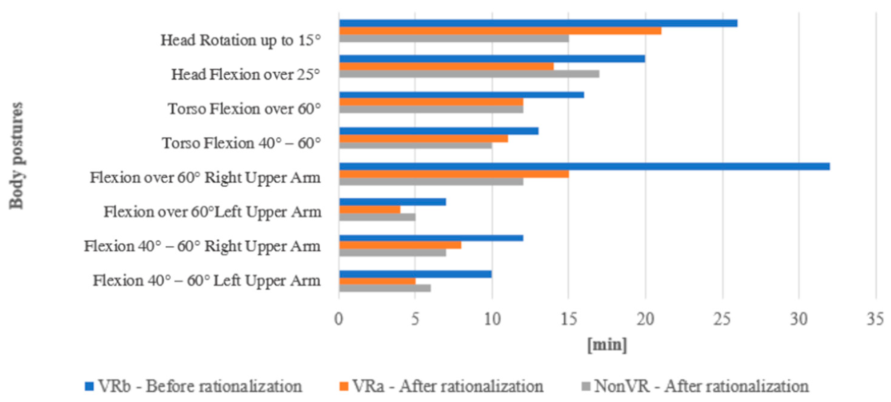
In the chart below (
Figure 9), time spent in certain working positions in conditionally acceptable or unacceptable positions is shown. As part of the initial analysis of the original workstation in the virtual environment, a significant problem with the position of the right upper limb was identified, this was corrected after rationalisation and the workload was reduced from 32 min to 12 min.
The rationalisation of the workplace eliminated the physical overloading of the right upper limb (shoulder) of the workers in the given work position not only in terms of working positions, but also in terms of local muscle load. As already mentioned, the manipulated part weighs around 1.5 kg, which is highly unacceptable in the case of working positions of upper limb flexion above 90°, as demonstrated by research [
2,
41,
42,
43]. If the KLT box is moved to the proposed position, the muscle load on the upper forearm will be significantly lower.
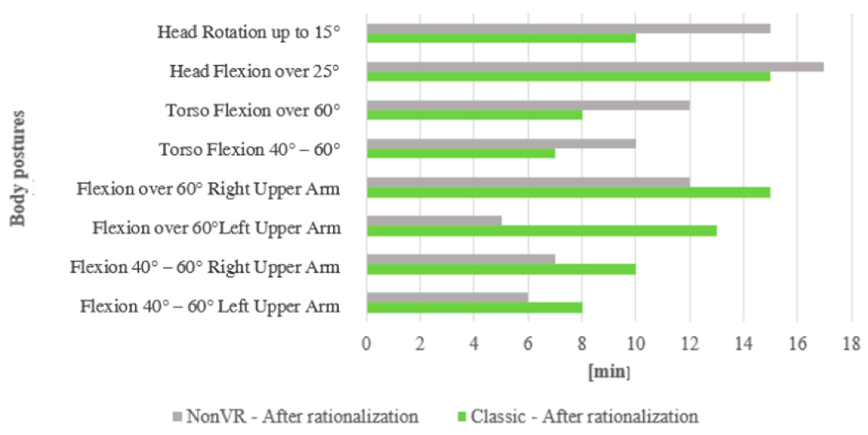
After the overall measurements, i.e., after the virtual reality measurements at the real workplace, the VR measurements after the workplace rationalisation, and the measurements at the real modified workplace using the kinematic suit, the measurements were compared with the classical method of measuring the ergonomics of working positions using biomechanical analysis.
The same workers were measured as part of the evaluation. From the measurements using biomechanical analysis after workplace rationalisation, the work positions were evaluated as follows, after conversion to an average 8-h shift. The graph shows a comparison of the results of the conventional method of measuring work positions and the measurements using the MoCap suit.
6.5. Results for Classic
The result from classical biomechanical analysis (deviation −2.99) (
Figure 10) is similar to the result using MoCap suit (deviation −4.03) (
Figure 9), while respecting the legislation, the only difference is in the measurement itself. We assess the position of the torso, head and neck, upper limbs, and other parts of the body. The degree of acceptability of the working position is determined by the range of changes in the position of the individual body parts based on the assumed risks of overloading of tendons, cartilage, and intervertebral discs. After classifying the assessed work postures as conditionally acceptable or unacceptable (or static or dynamic), a time analysis is then performed to assess whether the hygienic time limit for working in that posture in an average shift is exceeded for each work posture [
36].
Time spent in a particular working position (
Table 2) was cumulatively converted to an average 8-h shift. The table below shows the results of the VRa and NonVR methods.
6.6. Statistical Evaluation for VRa, NonVR, and Classic
Normality was not demonstrated by the Anderson-Darling test for evaluated data, therefore, a non-parametric test, the Wilcoxon paired test, was used for the evaluation.
We test the null hypothesis in that there is no statistically significant difference in the measurements:
We test at a significance level of α= 5%, i.e., we reject the null hypothesis if the p-value of the test comes out lower than 5%. In the case of rejection, we can claim that there is a statistically significant difference between the measurement values using the two different methods.
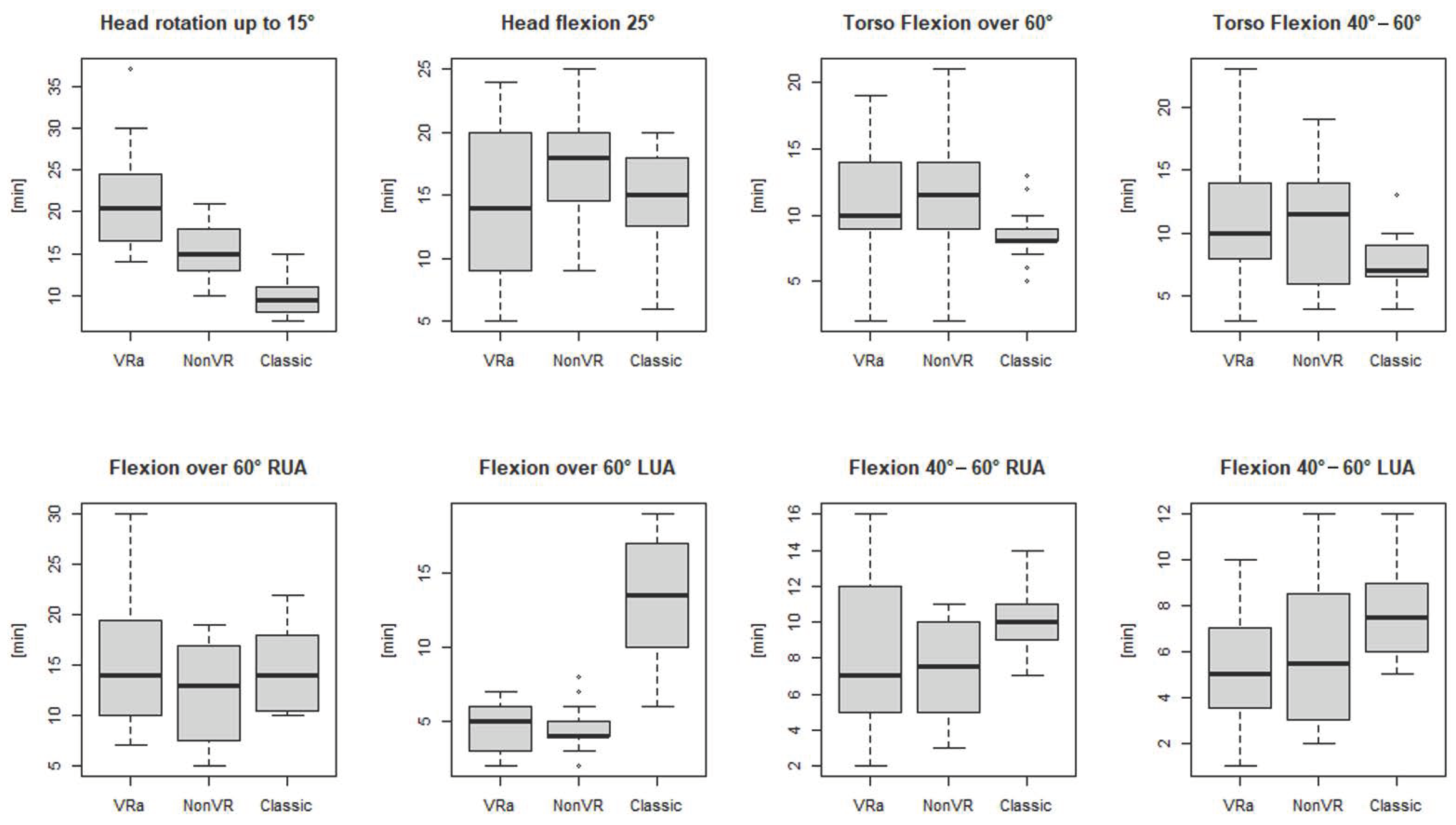
In (
Table 3) and in (
Figure 11), the resulting
p-values of the Wilcoxon test can be seen along with the values of the range of variation and the median (range means a range of variation).
A statistically significant difference between Motion Capture measurements with and without VR was demonstrated for Head rotation up to 15°, Head flexion 25°, and Flexion over 60° RUA. In the case of Head rotation up to 15° and Flexion over 60° RUA, significantly more minutes spent in these positions were measured when using VR, whereas the measured time in Head flexion 25° was lower when using VR. For all other positions, the measured time with and without the use of VR was comparable.
In the case of the comparison between Motion Capture measurements using VR and the classical method, a significant difference was, on the contrary, confirmed in almost all positions, except for Head Flexion over 60° RUA and Head Flexion 40–60° RUA.
In the case of the comparison between Motion Capture measurements using VR and the classical method, a significant difference was confirmed in almost all positions except Flexion over 60° RUA and Flexion 40–60° RUA. (However, in the case of Flexion 40–60° RUA, it can be seen that the p-value is very close to 5%—we would reject the null hypothesis at the 10% significance level; this is likely to be due to the greater variance in the VRa measurements). In half of the cases, there is a significant difference in that more minutes were measured in the case of VRa measurements than in the conventional method (Head rotation up to 15°, Torso Flexion over 60°, and Torso Flexion 40–60°), in the other positions, the situation is reversed. The most obvious difference was identified in the Flexion over 60° LUA position, where significantly more minutes were measured in this position with the conventional method than with VR.
7. Discussion
Now let’s discuss the benefits of using VR and MoCap technology for workplace rationalisation over the standard methods. The output data itself demonstrates the effectiveness of the rationalisation. However, the data taken during VRb and VRa phases cannot be directly compared as the measurements are produced at two different workplaces (before and after rationalisation). The disadvantage of the VR and MoCap method is the need for non-standard technical support (both HW and SW) and an advanced engineering force to perform the measurements. On the other hand, once the space is calibrated, it is very easy to perform these analyses repeatedly and at multiple sites simultaneously. The advantage is also a considerable material saving in terms of lack of prototyping: we can digitise workplaces, products, and semi-finished products that do not yet exist (simulations of workplaces located in potentially hazardous environments are also possible). It is also possible to verify many alternative solutions in a very short time. In the case of standard methods and the proposed advanced methods, however, the assistance of an ergonomist is still needed. The final form of the rationalisation is thus based on their experience. While making our measurements, we have encountered a feeling of concern among the ergonomists about replacing existing staff with new technologies, which is certainly not the ambition of this solution. It is a preliminary assistance tool to improve work efficiency.
Let us now compare the VRa and NonVR measurements. Both methods involve measurements at the same workplace, so here it is possible to compare the results. In principle, the only difference between the VR measurement and the control measurement in the real environment is the position of the observer within the virtual continuum (VR world/real world). Except for the measurement of torsional flexion at 60 degrees, a difference was always recorded (converted to a shift length of 8 h), with the distribution of measured differences being evenly distributed in favour of working in the real world and in favour of working in the virtual world. The average difference between the measurements is exactly 2 min, with the largest difference in head rotation, 6 min, clearly contributing to the disadvantage of VR. This can be explained by the fact that peripheral vision is limited in VR measurements (depending on the technology used) and forces the proband to look around their environment more. It would be interesting to conduct follow-up research to test this hypothesis by repeated measurements of probands who have been previously exposed to VR and to observe whether this difference is reduced in these workers. Another difference (3 min) can be observed for Flex over 60 degrees RUA. This may be due to the 1.5 kg part being grasped as part of the work process. While this is respected for the VR simulations and analysis, the worker only feels the weight of the controls during the measurement in VR. This issue is one of the fundamental difficulties of VR technologies. Again, however, follow-up research could be designed to focus only on this aspect (objects can also be placed in the real world and tracked in space using special devices).
On the basis of internal brainstorming, which was subsequently transferred to expert groups from the industry, it was decided that an average difference of 0.8 min when excluding head and hand movements that have to carry objects represents a more or less normal acceptable measurement deviation in ergonomic analyses. It will therefore be appropriate to look further into the head movements and use the above methods to determine, e.g., a "correction constant", which will depend mainly on the technology used (or even the order of exposure).
Comparing the results of the NonVR and Classic methods, we find that the results are quite different, which is to be expected. The average difference within the ergonomic categories studied is 3.75 min. This is due to the inaccuracy of the biomechanical analysis. With the MoCap method using the suit, we obtain more accurate results due to the precise time capture of each working position. The Classic method is on average three times more time-consuming. The actual measurement and evaluation with the biomechanical analysis on one person takes around 1.5 h, with the MoCap suit it is around 30 min quicker. Due to this, repeated measurements using Classic method are not actually performed in praxis.
As already mentioned, the research was performed at a reference facility that is more or less standardised. Therefore, it can be assumed that only the VRb and VRa phases will be possible for such workplaces when all the above constraints are met. For different workplaces, it is suggested that control measurements should also be performed.
Some authors focus on ergonomic risk assessment using conventional methods [
15,
44], while others use non-conventional methods to assess the workplace [
45,
46,
47]. Generally, researchers present conventional techniques or examine the possibilities of using recent technologies for improving ergonomic studies. The latest trend is to implement new features for non-conventional disruptive technology (like the haptic feedback presented in [
46]), but the comparison between conventional and unconventional techniques is missing. The advantage of our solution is the combination of the two approaches—conventional biomechanical analysis using video and a goniometer, and the modern virtual reality technology and Motion Capture suit to record a worker’s working positions. This is a unique approach to assessing work position and future categorisation of work in terms of legislation.
We can compare our findings with a recent article [
48], which also deals with a methodological framework and a pilot study validation for integration of a motion capture system and virtual reality for an assembly system. Our method is similar, but we include the comparison with conventional techniques directly into the methodology. In [
48] the proposed methodology is strictly based on the REBA score, but we consider the load of specific body parts.
8. Conclusions
Thanks to our research, we have arrived at an answer to the initial question “Can VR technology in combination with MoCap be used to implement ergonomic changes in working position with emphasis on upper limb loading in the assembly workplace?”.
The outputs from our pilot study demonstrate that the combination of VR technology and MoCap suits allows the ergonomic evaluation of an assembly workstation. All the working positions that a worker adopts during an activity, and not just the upper limbs, can be analysed with accurate assessment capabilities. These methods will always be more accurate than standard methods and have a number of advantages when hardware, software, and a worker who can operate the equipment are available. The results have shown that we can still fine tune the proposed procedure by targeting some problematic positions.
As the method was tested on a neutral assembly workstation (light manual assembly, standing at a workbench) which is found in almost all industrial companies, the method can be used in almost any industrial operation.
The practical implications of the proposed method are individual and depend on a company’s attributes. Currently, it is more suitable for big and medium industrial enterprises. These enterprises are forced to perform ergonomic testing more frequently. The most limiting factor for small enterprises is the current market price of hardware and software. On the other hand, the proposed method helps eliminate potential occupational diseases and health problems of workers, and therefore makes cost savings. Another important feature of this method is that it can reduce the cost of potential workplace changes, as designs can be validated in the pre-production or rebuilding phase. Each company has to individually review the rate of return on its investment.
As a further solution, the application can be extended to include the possibility of using hand tracking technology. This technology would allow probands to grasp objects using their virtual hands, which 1:1 capture the movement of real hands. The whole process would be even more closely aligned to the real one. We propose adding real objects that could also simulate their weight. However, it would be necessary to place the objects in locations that would match the 1:1 placement on the real workstation to guarantee the realism of the whole process. This opens up other possibilities for future research, such as linking to local upper limb muscle loads that can be calculated thanks to a mathematical model [
41], or using MoCap suits that support this technology, such as Tea Captiv [
42] or Xsens.
As mentioned earlier, we have found differences in the torsional flexion during real-world and VR exposure. This topic could be very interesting for a deeper examination in follow-up research. Additionally, we suggest doing research into the benefits of using real-world models for virtual objects during MoCap and VR ergonomic analyses.


