
Performance-Driven Engineering Design Approaches Based on Generative Design and Topology Optimization Tools: A Comparative Study


Abstract
:1. Introduction
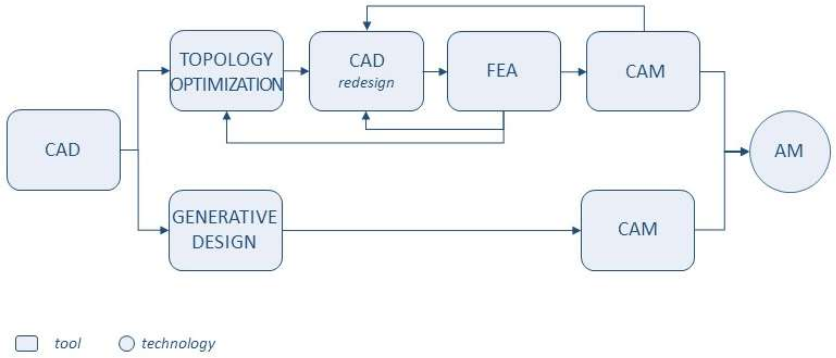
2. Design Methods Based on TO and GD Tools
2.1. Topology Optimization
2.2. Generative Design
3. Case Studies
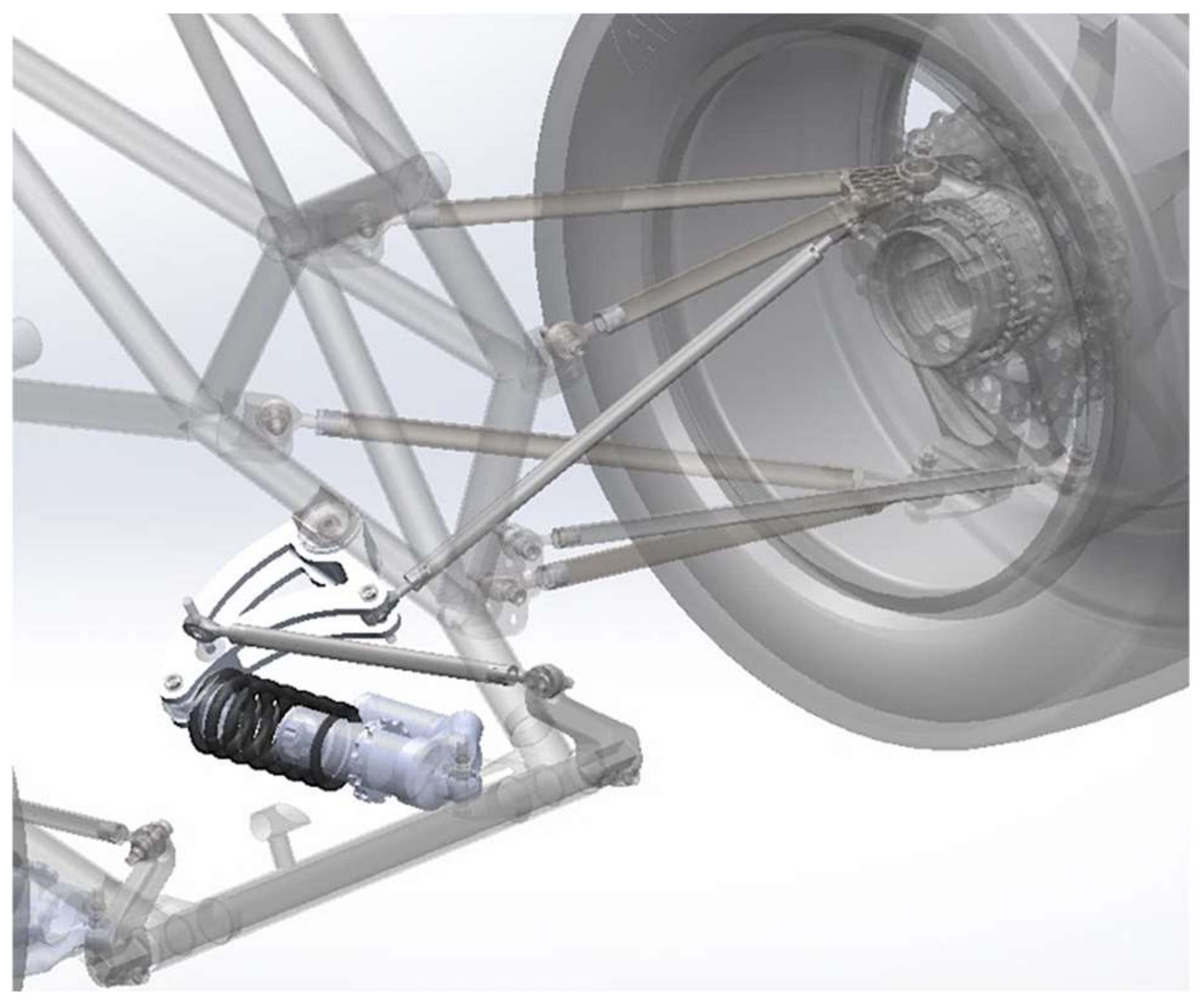
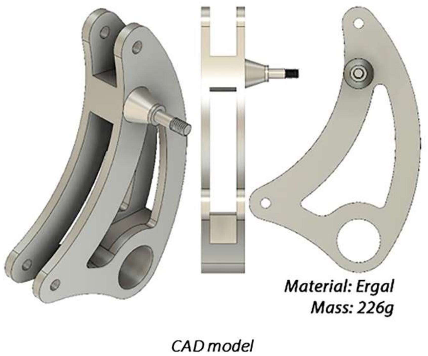
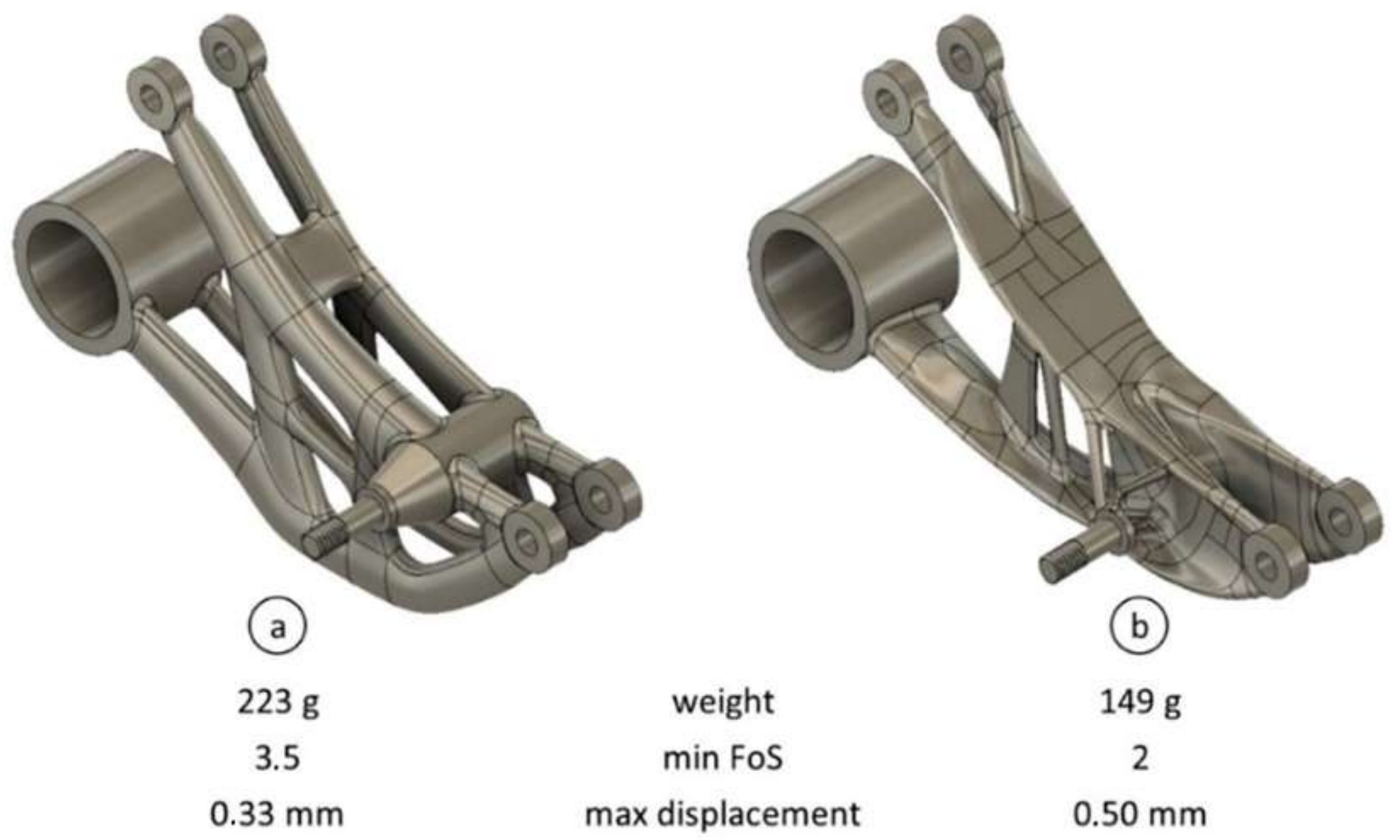
3.1. Rocker Arm
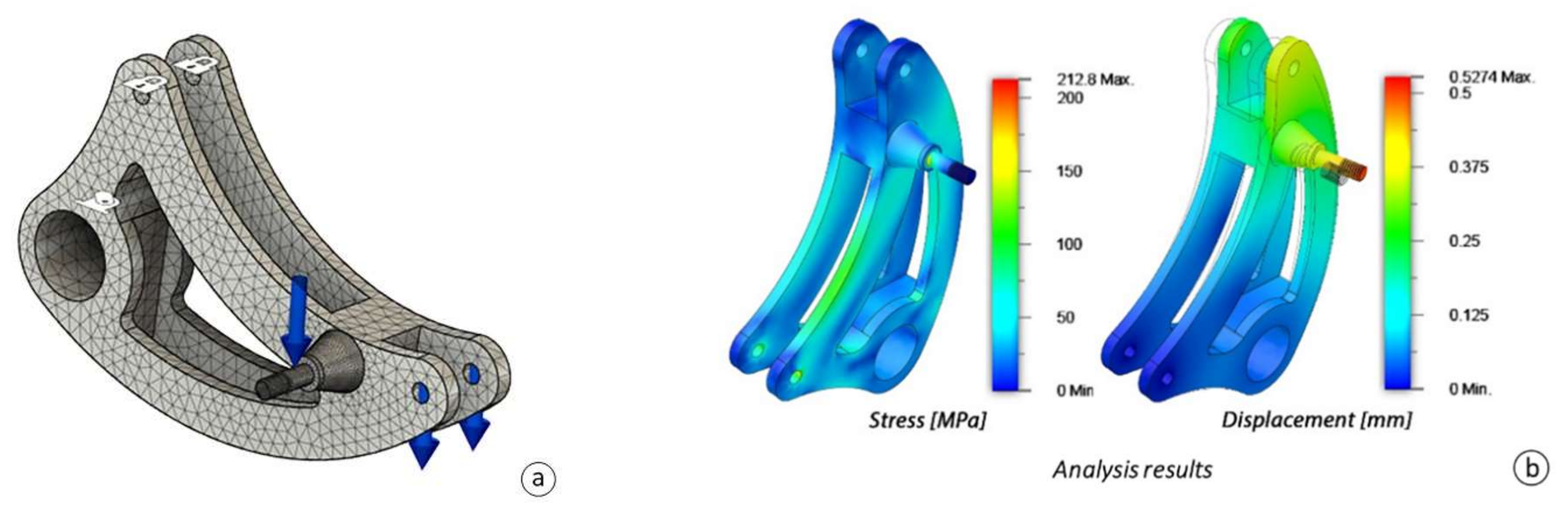
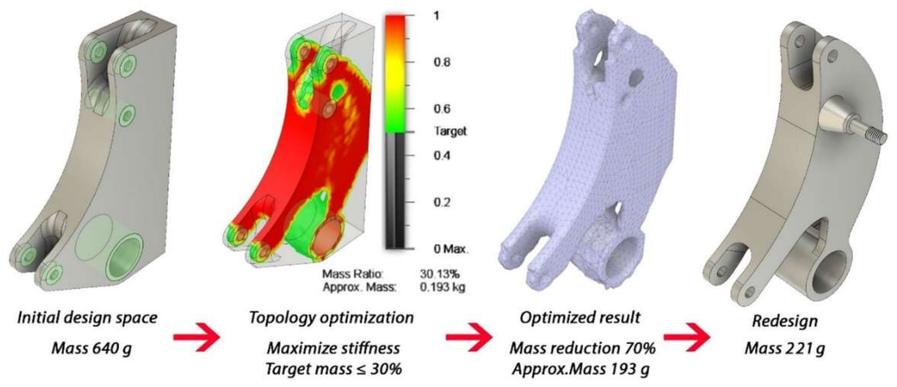
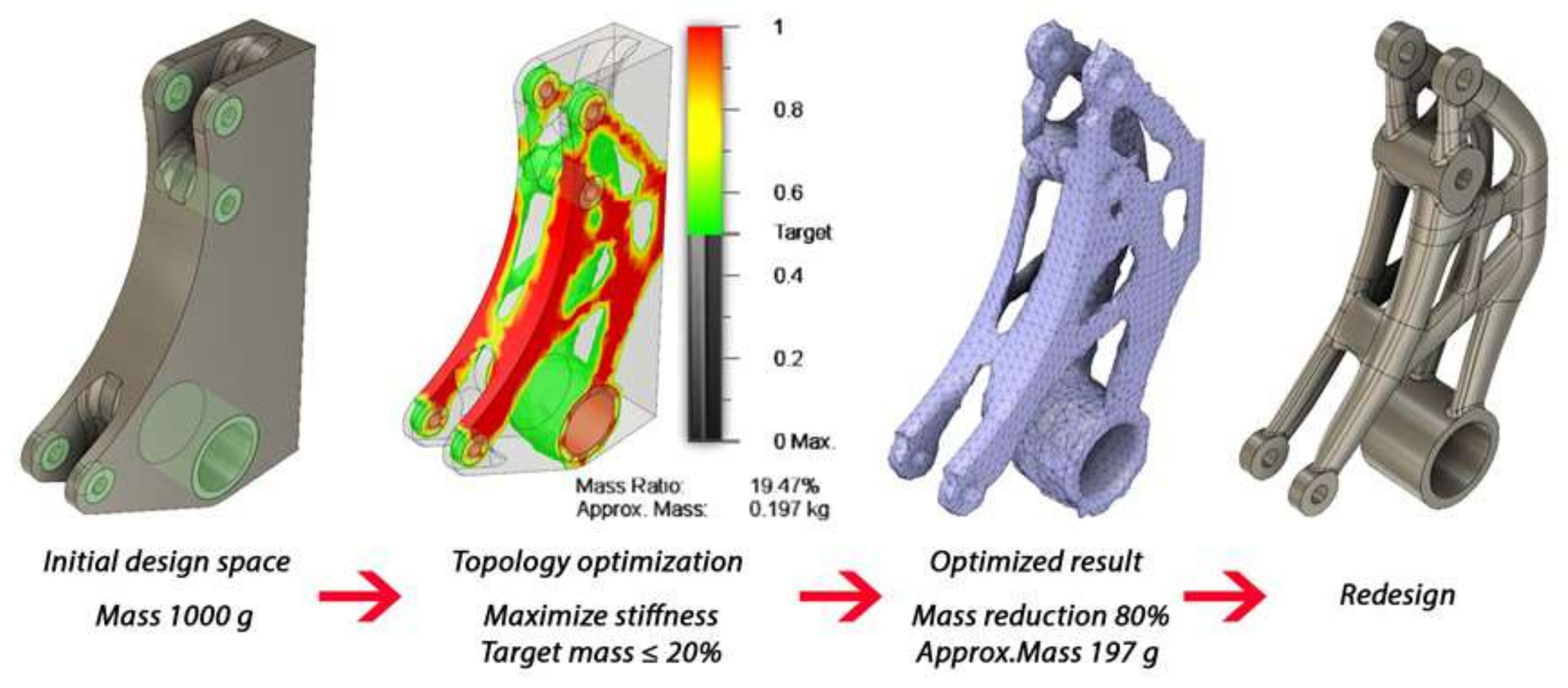
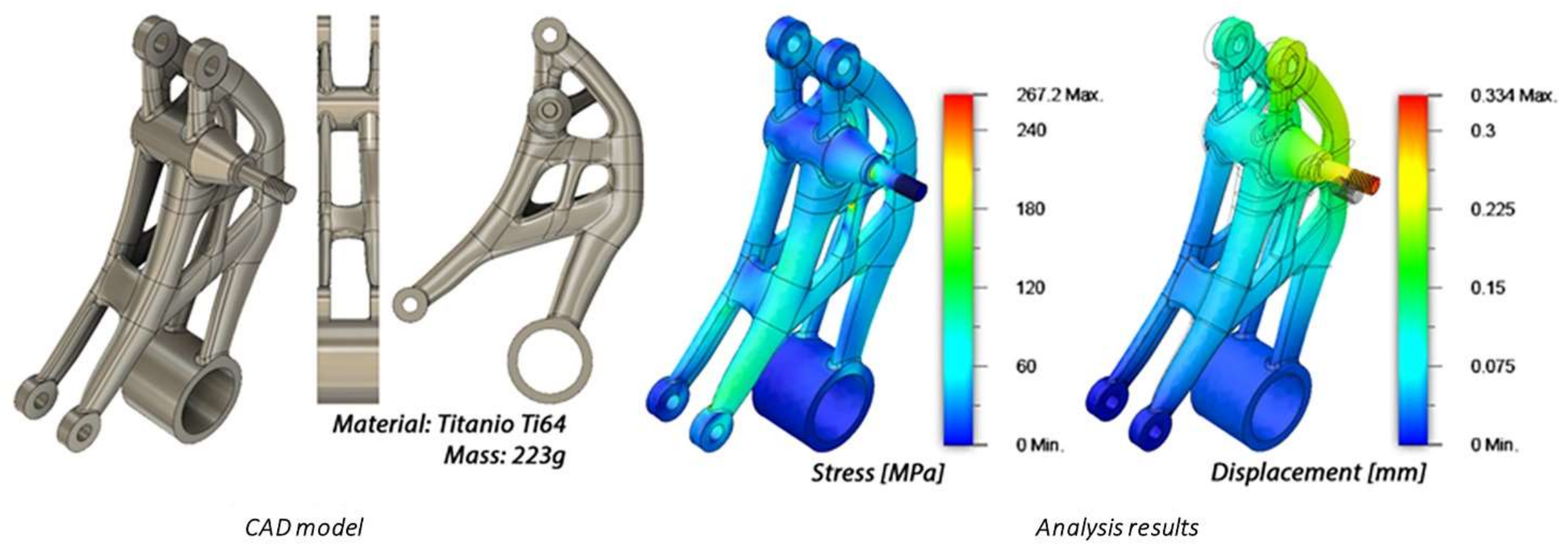
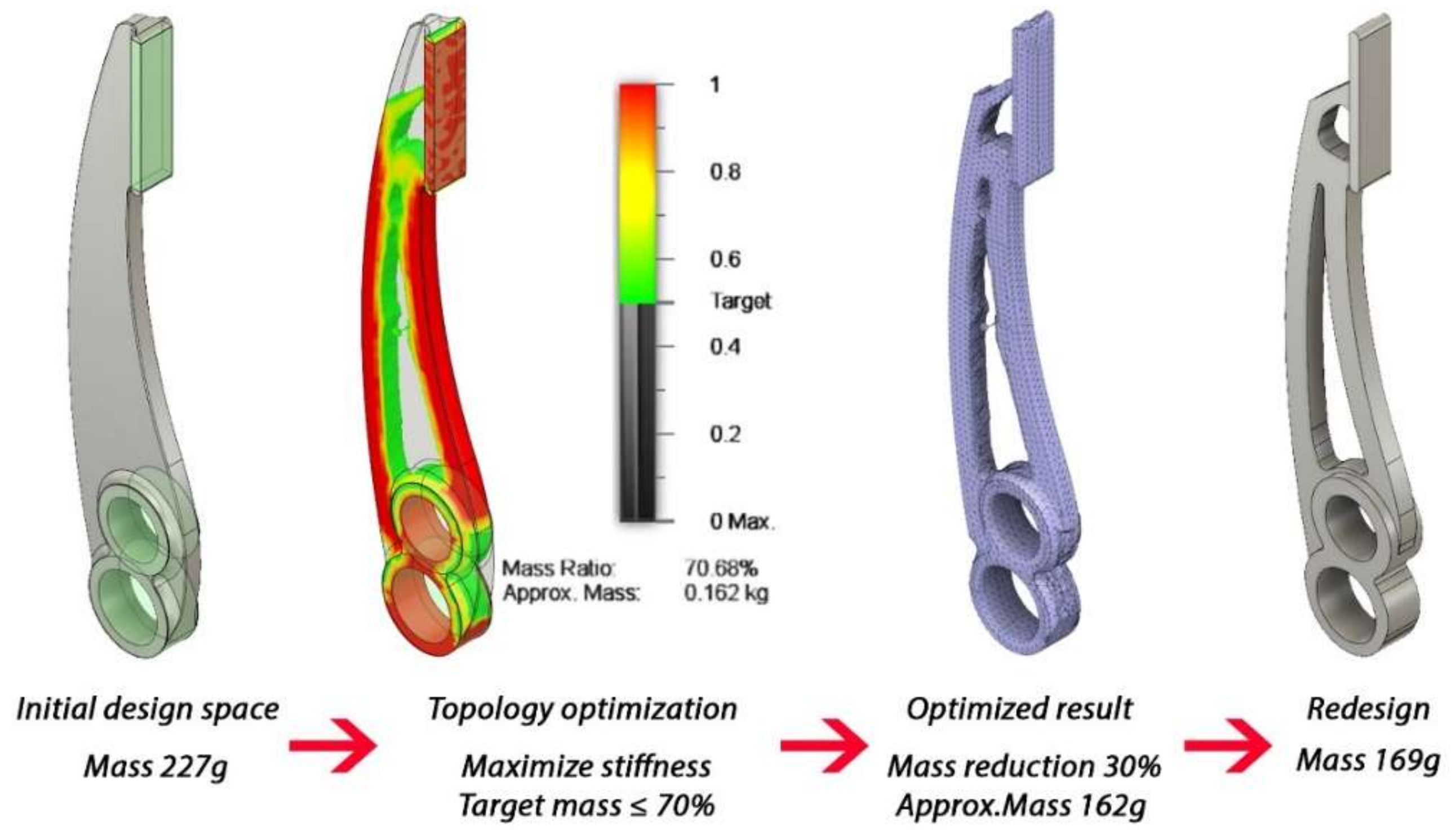
3.1.1. Topology Optimization Approach
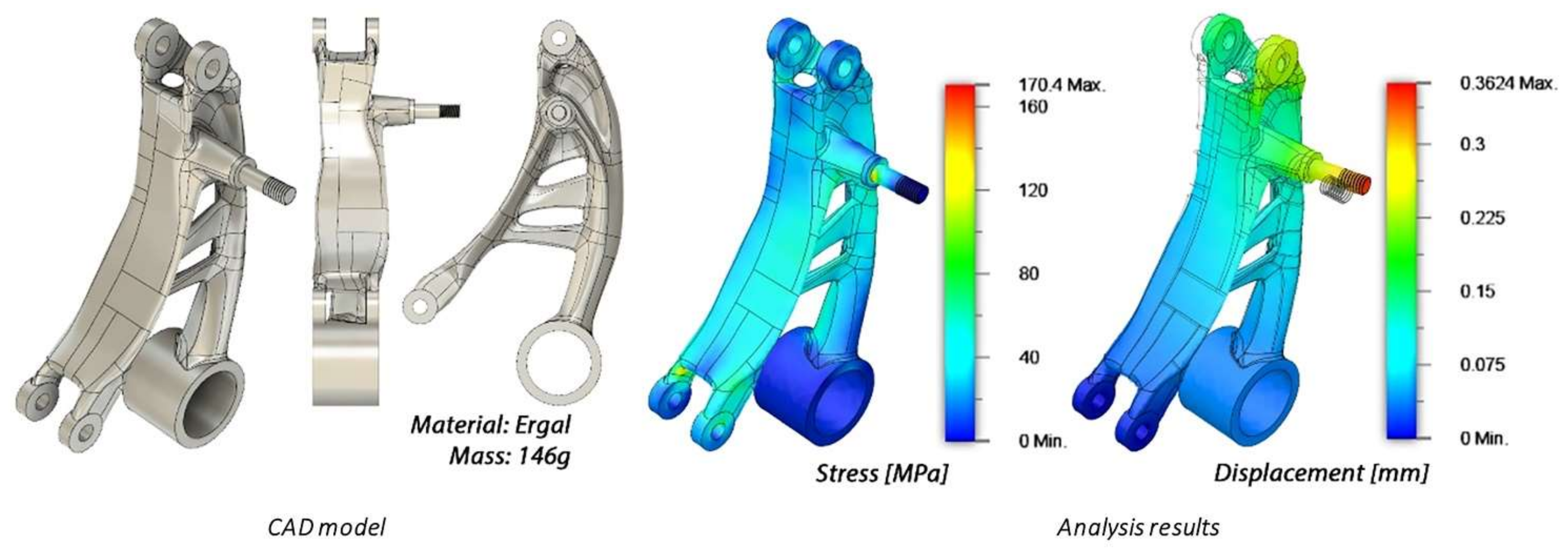
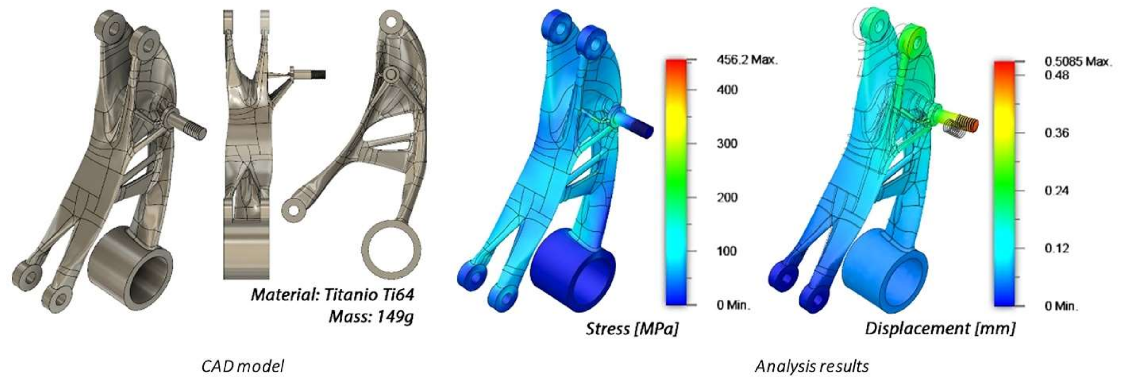
3.1.2. Generative Design Approach
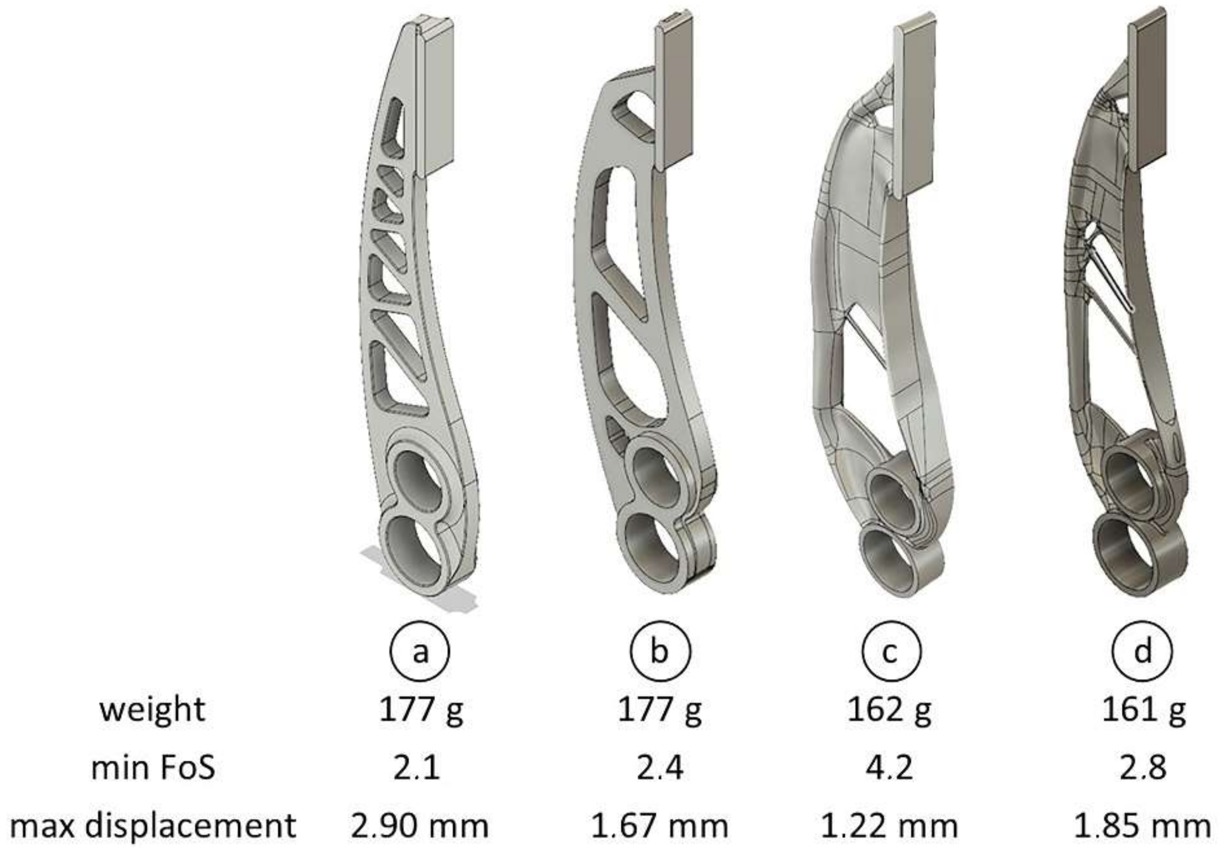
3.2. Brake Pedal
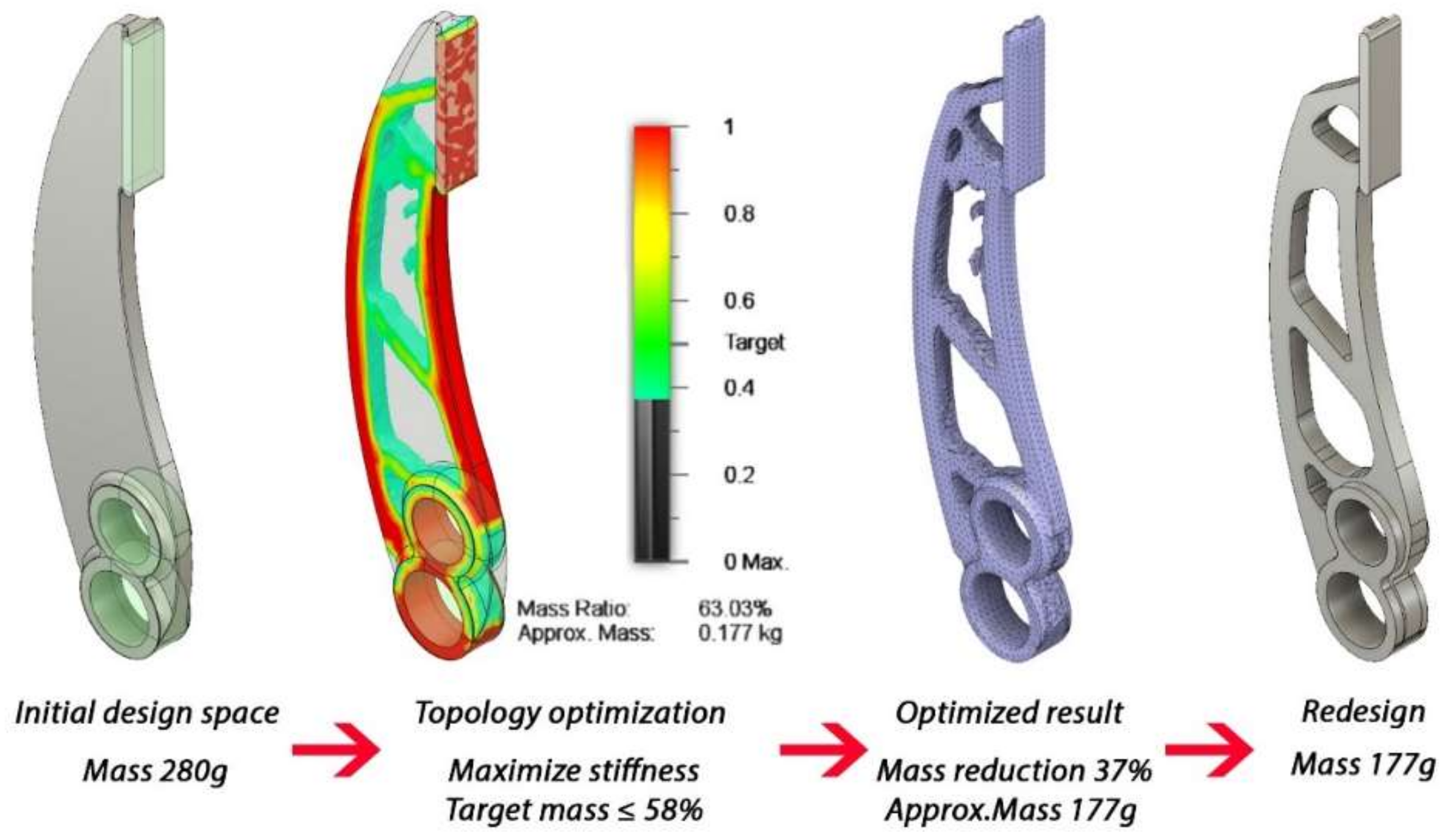
3.2.1. Topology Optimization Approach
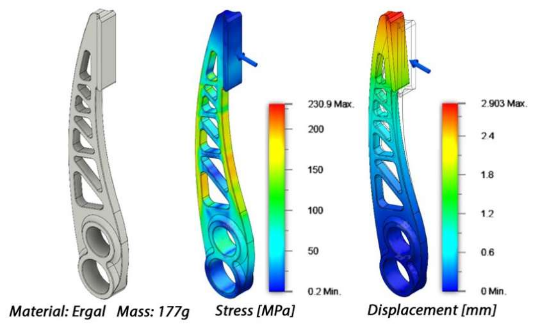
3.2.2. Generative Design Approach
4. Results
5. Conclusions
Author Contributions
Funding
Institutional Review Board Statement
Informed Consent Statement
Data Availability Statement
Conflicts of Interest
Nomenclature
| AM | Additive Manufacturing |
| CAD | Computer Aided Design |
| CAE | Computer Aided Engineering |
| CAM | Computer Aided Manufacturing |
| CAx | Computer Aided Technologies |
| CNC | Computer Numerical Control |
| DMLS | Direct Metal Laser Sintering |
| FEA | Finite Element Analysis |
| FEM | Finite Element Method |
| FoS | Factor of Safety |
| GD | Generative Design |
| TO | Topology Optimization |
References
- Tang, Y.; Zhao, Y.F. A survey of the design methods for Additive Manufacturing to improve functional performance. Rapid Prototyp. J. 2016, 22, 569–590. [Google Scholar] [CrossRef]
- Wiberg, A.; Persson, J.; Ölvander, J. Design for Additive Manufacturing—A review of available design methods and software. Rapid Prototyp. J. 2019, 25, 1080–1094. [Google Scholar] [CrossRef] [Green Version]
- Levy, G.N.; Schindel, R.; Kruth, J. Rapid manufacturing and rapid tooling with layer manufacturing (LM) technologies, state of the art and future perspectives. CIRP Ann. 2013, 52, 589–609. [Google Scholar] [CrossRef]
- Kruth, J.-P.; Leu, M.C.; Nakagawa, T. Progress in Additive Manufacturing and Rapid Prototyping. CIRP Ann. Manuf. Technol. 1998, 47, 525–540. [Google Scholar] [CrossRef]
- Vandenbroucke, B.; Kruth, J.-P. Selective laser melting of biocompatible metals for rapid manufacturing of medical parts. Rapid Prototyp. J. 2007, 13, 196–203. [Google Scholar] [CrossRef]
- Leal, R.; Barreiros, F.; Alves, M.; Romeiro, F.; Vasco, J.C.; Santos, M.; Marto, C. Additive Manufacturing tooling for the automotive industry. Int. J. Adv. Manuf. Technol. 2017, 92, 1671–1676. [Google Scholar] [CrossRef]
- Ituarte, I.F.; Chekurov, S.; Tuomi, J.; Mascolo, J.E.; Zanella, A.; Springer, P.; Partanen, J. Digital manufacturing applicability of a laser sintered component for automotive industry: A case study. Rapid Prototyp. J. 2018, 24, 1203–1211. [Google Scholar] [CrossRef]
- Ngo, T.D.; Kashani, A.; Imbalzano, G.; Nguyen, K.T.Q.; Hui, D. Additive Manufacturing (3D printing): A review of materials, methods, applications and challenges. Compos. Part B Eng. 2018, 143, 172–196. [Google Scholar] [CrossRef]
- Elsayed, M.; Ghazy, M.; Youssef, Y.; Essa, K. Optimization of SLM process parameters for Ti6Al4V medical implants. Rapid Prototyp. J. 2019, 25, 433–447. [Google Scholar] [CrossRef] [Green Version]
- Dankwort, C.W.; Weidlich, R.; Guenther, B.; Blaurock, J.E. Engineers’ CAx education—It’s not only CAD. Comput. Aided Des. 2004, 36, 1439–1450. [Google Scholar] [CrossRef]
- Barbieri, L.; Calzone, F.; Muzzupappa, M. Form and function: Functional optimization and Additive Manufacturing. In Advances on Mechanics, Design Engineering and Manufacturing II; Springer: Cham, Switzerland, 2019; pp. 649–658. [Google Scholar] [CrossRef]
- Bathe, K.J. Finite Element Procedures; Prentice Hall: Upper Saddle River, NJ, USA, 1996. [Google Scholar]
- Sandberg, M. Design for Manufacturing: Methods and Applications Using Knowledge Engineering. Ph.D. Dissertation, Luleå Tekniska Universitet, Luleå, Sweden, 2007. [Google Scholar]
- Thompson, M.K.; Moroni, G.; Vaneker, T.; Fadel, G.; Campbell, R.I.; Gibson, I.; Bernard, A.; Schulz, J.; Graf, P.; Ahuja, B.; et al. Design for Additive Manufacturing: Trends, opportunities, considerations, and constraints. CIRP Ann. 2016, 65, 737–760. [Google Scholar] [CrossRef] [Green Version]
- Pagac, M.; Hajnys, J.; Halama, R.; Aldabash, T.; Mesicek, J.; Jancar, L.; Jansa, J. Prediction of Model Distortion by FEM in 3D Printing via the Selective Laser Melting of Stainless Steel AISI 316L. Appl. Sci. 2021, 11, 1656. [Google Scholar] [CrossRef]
- Afazov, S.; Denmark, W.A.D.; Lazaro Toralles, B.; Holloway, A.; Yaghi, A. Distortion prediction and compensation in selectivelaser melting. Addit. Manuf. 2017, 17, 15–22. [Google Scholar] [CrossRef]
- Sotomayor, N.S.; Caiazzo, F.; Alfieri, V. Enhancing Design for Additive Manufacturing Workflow: Optimization, Design and Simulation Tools. Appl. Sci. 2021, 11, 6628. [Google Scholar] [CrossRef]
- Bendsoe, M.P.; Sigmund, O. Topology Optimization: Theory, Methods, and Applications; Springer: Berlin/Heidelberg, Germany, 2003. [Google Scholar]
- Bendsøe, M.P. Optimization of Structural Topology, Shape, and Material; Springer: Berlin/Heidelberg, Germany, 1995. [Google Scholar]
- Sigmund, O.; Maute, K. Topology Optimization Approaches: A comparative review. Struct. Multidiscip. Optim. 2013, 48, 1031–1055. [Google Scholar] [CrossRef]
- Ribeiro, T.; Bernardo, L.; Andrade, J. Topology Optimisation in Structural Steel Design for Additive Manufacturing. Appl. Sci. 2021, 11, 2112. [Google Scholar] [CrossRef]
- Vlah, D.; Žavbi, R.; Vukašinović, N. Evaluation of topology optimization and generative design tools as support for conceptual design. In Proceedings of the Design Society: Design Conference, Cavtat, Croatia, 26–29 October 2020; Cambridge University Press: Cambridge, UK, 2020; Volume 1, pp. 451–460. [Google Scholar] [CrossRef]
- Zhu, J.; Zhang, W.-H.; Xia, L. Topology Optimization in Aircraft and Aerospace Structures Design. Arch. Comput. Methods Eng. 2016, 23, 595–622. [Google Scholar] [CrossRef]
- Dunning, P.; Stanford, B.K.; Kim, H.A. Coupled aerostructural topology optimization using a level set method for 3D aircraft wings. Struct. Multidiscip. Optim. 2015, 51, 1113–1132. [Google Scholar] [CrossRef] [Green Version]
- Li, C.; Kim, I.Y.; Jeswiet, J. Conceptual and detailed design of an automotive engine cradle by using topology, shape, and size optimization. Struct. Multidiscip. Optim. 2014, 51, 547–564. [Google Scholar] [CrossRef]
- Chuang, C.-H.; Chen, S.; Yang, R.-J.; Vogiatzis, P. Topology optimization with Additive Manufacturing consideration for vehicle load path development. Int. J. Numer. Methods Eng. 2018, 113, 1434–1445. [Google Scholar] [CrossRef]
- Sutradhar, A.; Park, J.; Carrau, D.; Nguyen, T.; Miller, M.J.; Paulino, G.H. Designing patient-specific 3D printed craniofacial implants using a novel topology optimization method. Med. Biol. Eng. Comput. 2016, 54, 1123–1135. [Google Scholar] [CrossRef] [PubMed]
- Wang, X.; Xu, S.; Zhou, S.; Xu, W.; Leary, M.; Choong, P.; Qian, M.; Brandt, M.; Xie, Y.M. Topological design and Additive Manufacturing of porous metals for bone scaffolds and orthopaedic implants: A review. Biomaterials 2016, 83, 127–141. [Google Scholar] [CrossRef] [PubMed]
- Ma, H.; Wang, J.; Lu, Y.; Guo, Y. Lightweight design of turnover frame of bridge detection vehicle using topology and thickness optimization. Struct. Multidiscip. Optim. 2019, 59, 1007–1019. [Google Scholar] [CrossRef]
- Wu, S.; Zhang, Y.; Liu, S. Topology optimization for minimizing the maximum temperature of transient heat conduction structure. Struct. Multidiscip. Optim. 2019, 60, 69–82. [Google Scholar] [CrossRef]
- Eschenauer, H.A.; Niels, O. Topology optimization of continuum structures: A review. Appl. Mech. Rev. 2001, 54, 331–390. [Google Scholar] [CrossRef]
- Harzheim, L.; Gerhard, G. A review of optimization of cast parts using topology optimization. Struct. Multidiscip. Optim. 2006, 31, 388–399. [Google Scholar] [CrossRef]
- Dbouk, T. A review about the engineering design of optimal heat transfer systems using topology optimization. Appl. Therm. Eng. 2017, 112, 841–854. [Google Scholar] [CrossRef]
- Cucinotta, F.; Guglielmino, E.; Longo, G.; Risitano, G.; Santonocito, D.; Sfravara, F. Topology Optimization Additive Manufacturing-Oriented for a Biomedical Application. In Advances on Mechanics, Design Engineering and Manufacturing II; Springer: Cham, Switzerland, 2019; pp. 184–193. [Google Scholar]
- Hällgren, S.; Pejryd, L.; Ekengren, J. (Re)Design for Additive Manufacturing. Procedia CIRP 2016, 50, 246–251. [Google Scholar] [CrossRef] [Green Version]
- Mohiuddin, M.V.; Khan, M.A. Re-design of an Aircraft Bracket Using Topology Optimization Technique. Int. J. Mech. Eng. 2020, 7, 42–53. [Google Scholar] [CrossRef]
- Dalpadulo, E.; Gherardini, F.; Pini, F.; Leali, F. Integration of Topology Optimisation and Design Variants Selection for Additive Manufacturing-Based Systematic Product Redesign. Appl. Sci. 2020, 10, 7841. [Google Scholar] [CrossRef]
- Nieto, D.; Sánchez, D. Design for Additive Manufacturing: Tool Review and a Case Study. Appl. Sci. 2021, 11, 1571. [Google Scholar] [CrossRef]
- Raffaeli, R.; Lettori, J.; Schmidt, J.; Peruzzini, M.; Pellicciari, M. A Systematic Approach for Evaluating the Adoption of Additive Manufacturing in the Product Design Process. Appl. Sci. 2021, 11, 1210. [Google Scholar] [CrossRef]
- Lindemann, C.; Reiher, T.; Jahnke, U.; Koch, R. Towards a sustainable and economic selection of part candidates for Additive Manufacturing. Rapid Prototyp. J. 2015, 21, 216–227. [Google Scholar] [CrossRef]
- Barbieri, L.; Bruno, F.; Muzzupappa, M.; Cugini, U. Design automation tools as a support for knowledge management in topology optimization. In Proceedings of the ASME 2008 International Design Engineering Technical Conferences and Computers and Information in Engineering Conference, American Society of Mechanical Engineers Digital Collection, Brooklyn, NY, USA, 3–6 August 2008; pp. 1227–1234. [Google Scholar] [CrossRef]
- Larsen, S.; Jensen, C.G. Converting Topology Optimization Results into Parametric CAD Models. Comput. Aided Des. Appl. 2009, 6, 407–418. [Google Scholar] [CrossRef] [Green Version]
- Muzzupappa, M.; Barbieri, L.; Bruno, F. Integration of topology optimisation tools and knowledge management into the virtual Product Development Process of automotive components. Int. J. Prod. Dev. 2011, 14, 14. [Google Scholar] [CrossRef]
- Muzzupappa, M.; Barbieri, L.; Bruno, F.; Cugini, U. Methodology and Tools to Support Knowledge Management in Topology Optimization. J. Comput. Inf. Sci. Eng. 2010, 10, 044503. [Google Scholar] [CrossRef]
- Stangl, T.; Wartzack, S. Feature based interpretation and reconstruction of structural topology optimization results. In Proceedings of the DS 80-6 Proceedings of the 20th International Conference on Engineering Design (ICED 15) Vol 6: Design Methods and Tools-Part 2, Milan, Italy, 27–30 July 2015; pp. 235–244. [Google Scholar]
- Zegard, T.; Paulino, G.H. Bridging topology optimization and Additive Manufacturing. Struct. Multidiscip. Optim. 2016, 53, 175–192. [Google Scholar] [CrossRef]
- Jiu, L.; Zhang, W.; Meng, L.; Zhou, Y.; Chen, L. A CAD-oriented structural topology optimization method. Comput. Struct. 2020, 239, 106324. [Google Scholar] [CrossRef]
- Rosso, S.; Uriati, F.; Grigolato, L.; Meneghello, R.; Concheri, G.; Savio, G. An Optimization Workflow in Design for Additive Manufacturing. Appl. Sci. 2021, 11, 2572. [Google Scholar] [CrossRef]
- Bendsøe, M.P. Optimal shape design as a material distribution problem. Struct. Optim. 1989, 1, 193–202. [Google Scholar] [CrossRef]
- Sigmund, O. On the usefulness of non-gradient approaches in topology optimization. Struct. Multidiscip. Optim. 2011, 43, 589–596. [Google Scholar] [CrossRef]
- Kaminakis, N.T.; Stavroulakis, G. Topology optimization for compliant mechanisms, using evolutionary-hybrid algorithms and application to the design of auxetic materials. Compos. Part B Eng. 2012, 43, 2655–2668. [Google Scholar] [CrossRef]
- Bendsøe, M.P.; Sigmund, O. Material interpolation schemes in topology optimization. Arch. Appl. Mech. 1999, 69, 635–654. [Google Scholar] [CrossRef]
- Caetano, I.; Santos, L.; Leitão, A. Computational design in architecture: Defining parametric, generative, and algorithmic design. Front. Arch. Res. 2020, 9, 287–300. [Google Scholar] [CrossRef]
- McKnight, M. Generative Design: What it is? How is it being used? Why it’s a game changer. KnE Eng. 2017, 2, 176–181. [Google Scholar] [CrossRef] [Green Version]
- McCormack, J.P.; Dorin, A.; Innocent, T.C. Generative design: A paradigm for design research. In Future Ground; Redmond, J., Durling, D., de Bono, A., Eds.; Monash University: Melbourne, Australia, 2005; Volume 2. [Google Scholar]
- Sun, H.; Ma, L. Generative Design by Using Exploration Approaches of Reinforcement Learning in Density-Based Structural Topology Optimization. Designs 2020, 4, 10. [Google Scholar] [CrossRef]
- Frazer, J.H. An Evolutionary Architecture; Architectural Association Publications: London, UK, 1995. [Google Scholar]
- Caldas, L. Generation of energy-efficient architecture solutions applying GENE_ARCH: An evolution-based generative design system. Adv. Eng. Inform. 2008, 22, 59–70. [Google Scholar] [CrossRef]
- Abdelmohsen, S. Reconfiguring Architectural Space Using Generative Design and Digital Fabrication: A Project Based Course. In Proceedings of the XVII Conference of the Iberoamerican Society of DigitalGraphics—SIGraDi: Knowledge-Based Design; Editora Edgard Blucher, Ltd.: São Paulo, Brazil, 2013; pp. 391–395. [Google Scholar]
- Chaszar, A.; Joyce, S.C. Generating freedom: Questions of flexibility in digital design and architectural computation. Int. J. Arch. Comput. 2016, 14, 167–181. [Google Scholar] [CrossRef]
- Mountstephens, J.; Teo, J. Progress and Challenges in Generative Product Design: A Review of Systems. Computers 2020, 9, 80. [Google Scholar] [CrossRef]
- Wu, J.; Qian, X.; Wang, M.Y. Advances in generative design. Comput. Aided Des. 2019, 116, 102733. [Google Scholar] [CrossRef]
- Buonamici, F.; Carfagni, M.; Furferi, R.; Volpe, Y.; Governi, L. Generative Design: An Explorative Study. Comput. Aided Des. Appl. 2020, 18, 144–155. [Google Scholar] [CrossRef]
- Bhat, A.; Gupta, V.; Aulakh, S.S.; Elsen, R.S. Generative design and analysis of a double-wishbone suspension assembly: A methodology for developing constraint oriented solutions for optimum material distribution. J. Eng. Des. Technol. 2021. [Google Scholar] [CrossRef]
- Schelhorn, L.; Gosch, M.; Debeugny, L.; Schröter, P.; Schwarz, W.; Soller, S. Optimal Design and Process Simulation for Additive Manufacturing. In Proceedings of the 8th European Conference for Aeronautics and Space Sciences, Madrid, Spain, 1–4 July 2019. [Google Scholar]
- Marinov, M.; Amagliani, M.; Barback, T.; Flower, J.; Barley, S.; Furuta, S.; Charrot, P.; Henley, I.; Santhanam, N.; Finnigan, G.T.; et al. Generative Design Conversion to Editable and Watertight Boundary Representation. CAD Comput. Aided Des. 2019, 115, 194–205. [Google Scholar] [CrossRef]
- Autodesk Fusion 360. Available online: https://www.autodesk.com/products/fusion-360 (accessed on 11 February 2022).
- Khaing, M.; Fuh, J.; Lu, L. Direct metal laser sintering for rapid tooling: Processing and characterisation of EOS parts. J. Mater. Process. Technol. 2001, 113, 269–272. [Google Scholar] [CrossRef]
- Tyflopoulos, E.; Tollnes, F.D.; Steinert, M.; Olsen, A. State of the art of generative design and topology optimization and potential research needs. In Proceedings of the DS 91: Proceedings of NordDesign 2018, Linköping, Sweden, 14–17 August 2018. [Google Scholar]


Publisher’s Note: MDPI stays neutral with regard to jurisdictional claims in published maps and institutional affiliations. |
© 2022 by the authors. Licensee MDPI, Basel, Switzerland. This article is an open access article distributed under the terms and conditions of the Creative Commons Attribution (CC BY) license (https://creativecommons.org/licenses/by/4.0/).
Share and Cite
Barbieri, L.; Muzzupappa, M. Performance-Driven Engineering Design Approaches Based on Generative Design and Topology Optimization Tools: A Comparative Study. Appl. Sci. 2022, 12, 2106. https://doi.org/10.3390/app12042106
Barbieri L, Muzzupappa M. Performance-Driven Engineering Design Approaches Based on Generative Design and Topology Optimization Tools: A Comparative Study. Applied Sciences. 2022; 12(4):2106. https://doi.org/10.3390/app12042106
Chicago/Turabian StyleBarbieri, Loris, and Maurizio Muzzupappa. 2022. "Performance-Driven Engineering Design Approaches Based on Generative Design and Topology Optimization Tools: A Comparative Study" Applied Sciences 12, no. 4: 2106. https://doi.org/10.3390/app12042106