
Modular Combined DC-DC Autotransformer for Offshore Wind Power Integration with DC Collection


Abstract
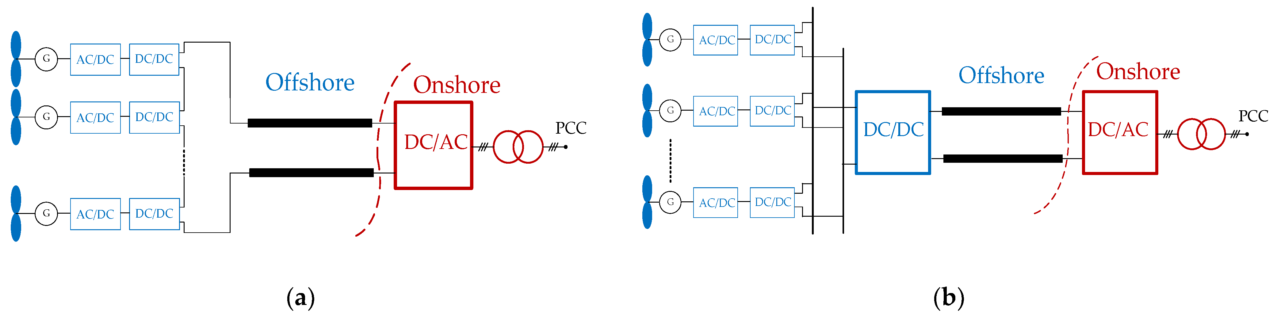
:1. Introduction
2. MCAT Topology and Its Operation Principles
2.1. Topological Structure
- (1)
- Coordinating the AC system voltage and the AC output voltage of MMC.
- (2)
- Galvanic separation between the AC system and the MMC to eliminate the DC offset voltage.
- (3)
- Acting as the inductor to smooth the current and suppress the fault current.
2.2. Operation Principles of the MCAT
3. MCAT Main Circuit Parameters Selection
3.1. Parameter Calculation of DC-Isolation Capacitors and Compensation Inductors in HVM
3.2. Parameter Calculation of DC-Isolation Capacitors and Compensation Inductors in LVM
- (1)
- When M = 1, the DC-isolation capacitors and compensation inductors are excluded from the LVM.
- (2)
- When M = 2, 4, 6, …, MMCL,M/2 (and MMCL,(M/2) +1) has the lowest DC offset voltage in the LVM, and αL,M/2 (and αL,(M/2)+1) is largest correspondingly.
- (3)
- When M = 3, 5, 7, …, MMCL,(M−1)/2 (and MMCL,(M+3)/2) has the lowest DC offset voltage, and αL, (M−1)/2 (and αL, (M+3)/2) is largest correspondingly.
4. Control Strategy of the MCAT
4.1. Dynamic Characteristics of the AC Side in the MCAT
4.2. MCAT Control Strategy in Normal Operation
4.3. MCAT AC-Side Short-Circuit Fault Recovery Strategy
5. Simulation Study
5.1. Test System
5.2. Simulation of Wind Speed Variation
5.3. Simulation of the Recovery Strategy
- (1)
- At t = 0.2 s, the three-phase short circuit fault occurs at the AC bus, and the fault time lasts for 0.1 s. At t = 0.202 s, the MCAT, DAB converters inside WTs and onshore converters are blocked. An AC chopper facilitates the WT to consume the surplus energy and limits the DC overvoltage. At t = 0.206 s, the fault current reduces to 0 due to the blocked MCAT.
- (2)
- At t = 0.3 s, the MCAT is unblocked, while the control strategy of MMCH,1 is switched from passive control to DC voltage control (reference value is 100 kV) and reactive power control (reference value is 0 MVar). At the same time, DAB converters inside WTs and onshore converters are unblocked. At t = 0.6 s, MMCH,1 is switched to passive control again. Figure 6 shows the simulation diagram of fault response characteristics of the test system.
6. Conclusions
- The proposed MCAT utilizes the DC-isolation capacitor to isolate the DC offset voltage of the converter transformers. The application of the compensation inductors facilitates improving the operation efficiency of the MCAT. The time-domain simulation results show that the calculation method of the main circuit parameters is correct, and the calculated values are highly consistent with the simulated values.
- Ignoring the dynamic characteristics of MMC submodules, the output characteristics of the MCAT and the AC bus voltage could be regulated by MMCs adopting DC voltage control, reactive power control, and passive control strategies, respectively. The time-domain simulation proves that the voltage across the MCAT can remain stable under the condition of wind speed changes, and the output power can quickly respond to the wind speed changes. This indicates that the MCAT has favorable voltage control performance.
- The fault recovery strategy proposed in this paper can help the MACT to quickly enter steady state. The test system is built in PSCAD/EMTDC, and the time-domain simulation shows that the MCAT could resume operation in a short time after the AC fault, which is conducive to maintaining the stable operation of the OWF.
Author Contributions
Funding
Institutional Review Board Statement
Informed Consent Statement
Data Availability Statement
Conflicts of Interest
Appendix A

| Symbols | Explanations of Symbols | Symbols | Explanations of Symbols |
|---|---|---|---|
| ucj | the voltage of Cj | uvacL,M/2 | AC component of uvL,M/2 |
| Uvdcj | DC component of ucj | UvdcH,N | DC component of uvH,N |
| Δucj | AC component of ucj | UvdcL,M/2 | DC component of uvL,M/2 |
| Uvacj | fundamental RMS L-L voltage at MMCj valve side | UvacH,N | Fundamental component of uvacH,N |
| Ij | fundamental RMS line current at MMCj valve side | UvacL,M/2 | Fundamental component of uvacL,M/2 |
| δj | the phase angle between Uvacj and Ij | UdcH,N | DC voltage of MMCH,N |
| ΔUcj | fundamental RMS voltage of Δucj | UdcL,M/2 | DC voltage of MMCL,M/2 |
| f | fundamental frequency at the MCAT AC side | uvH,N | the voltage at MMCH,N valve side |
| αj | fluctuation ratio of ucj | uvL,M/2 | the voltage at MMC L,M/2 valve side |
| αH,N | fluctuation ratio of uCH,N | uvacH,N | AC component of uvH,N |
| αL,M/2 | fluctuation ratio of uCL,M/2 |
References
- Wang, Q.; Yu, Z.; Ye, R.; Lin, Z.; Tang, Y. An ordered curtailment strategy for offshore wind power under extreme weather conditions considering the resilience of the grid. IEEE Access 2019, 7, 54824–54833. [Google Scholar] [CrossRef]
- Bresesti, P.; Kling, W.L.; Hendriks, R.L.; Vailati, R. HVDC connection of offshore wind farms to the transmission system. IEEE Trans. Energy Convers. 2007, 22, 37–43. [Google Scholar] [CrossRef]
- Elliott, D.; Bell, K.R.W.; Finney, S.J.; Adapa, R.; Brozio, C.; Yu, J.; Hussain, K. A comparison of AC and HVDC options for the connection of offshore wind generation in Great Britain. IEEE Trans. Power 2016, 31, 798–809. [Google Scholar] [CrossRef] [Green Version]
- Engel, S.P.; Stieneker, M.; Soltau, N.; Rabiee, S.; Stagge, H.; de Doncker, R.W. Comparison of the modular multilevel DC converter and the dual-active bridge converter for power conversion in HVDC and MVDC grids. IEEE Trans. Power Electron. 2015, 30, 124–137. [Google Scholar] [CrossRef]
- Lumbreras, S.; Ramos, A. Offshore wind farm electrical design: A review. Wind Energy 2013, 16, 459–473. [Google Scholar] [CrossRef]
- Taherbaneh, M.; Jovcic, D.; Taisne, J.P.; Nguefeu, S. DC fault performance and cost analysis of dc grids for connecting multiple offshore wind farms. In Proceedings of the 2013 IEEE Grenoble PowerTech (POWERTECH), Grenoble, France, 16–20 June 2013. [Google Scholar]
- Deng, F.; Chen, Z. Operation and control of a DC-grid offshore wind farm under DC transmission system faults. IEEE Trans. Power Deliv. 2013, 28, 1356–1363. [Google Scholar] [CrossRef]
- Robinson, J.; Jovcic, D.; Joos, G. Analysis and design of an offshore wind farm using a MV DC grid. IEEE Trans. Power Del. 2010, 25, 2164–2173. [Google Scholar] [CrossRef]
- Lian, Y.; Adam, G.; Holliday, D.; Finney, S. Medium-voltage DC/DC converter for offshore wind collection grid. IET Renew. Power Gener. 2016, 5, 651–660. [Google Scholar] [CrossRef]
- Hu, P.; Yin, R.; Wei, B.; Luo, Y.; Blaabjerg, F. Modular Isolated LLC DC/DC Conversion System for Offshore Wind Farm Collection and Integration. IEEE J. Emerg. Sel. Top. Power Electron. 2021, 9, 6713–6725. [Google Scholar] [CrossRef]
- Hu, P.; Yin, R.; He, Z.; Wang, C. A Modular Multiple DC Transformer Based DC Transmission System for PMSG Based Offshore Wind Farm Integration. IEEE Access 2020, 8, 15736–15746. [Google Scholar] [CrossRef]
- Páez, J.D.; Frey, D.; Maneiro, J.; Bacha, S.; Dworakowski, P. Overview of DC-DC Converters Dedicated to HVDC Grids. IEEE Trans. Power Deliv. 2019, 34, 119–128. [Google Scholar]
- Parastar, A.; Kang, Y.C.; Seok, J.-K. Multilevel modular DC/DC power converter for high-voltage DC-connected offshore wind energy applications. IEEE Trans. Ind. Electron. 2015, 5, 2879–2890. [Google Scholar] [CrossRef]
- Lin, W. DC-DC autotransformer with bidirectional DC fault isolating capability. IEEE Trans. Power Electron. 2015, 31, 5400–5410. [Google Scholar] [CrossRef]
- Li, X.Y.; Zhu, M.; Su, M.; Ma, J.; Li, Y.R.; Cai, X. Input-independent and output-series connected modular DC–DC converter with intermodule power balancing units for MVdc Integration of distributed PV. IEEE Trans. Power Electron. 2020, 35, 1622–1636. [Google Scholar] [CrossRef]
- Chen, Y.; Wang, H.; Zhu, M.; Liu, M.; Cai, X. Modular DC-DC auto-transformer: Topology, operation, and system design. IET Power Electron. 2021, 14, 2289–2302. [Google Scholar] [CrossRef]
- Xu, Z.; Tu, Q.; Guan, M. Voltage Source Converter Based HVDC Power Transmission Systems, 2nd ed.; China Machine Press: Beijing, China, 2013. [Google Scholar]
- Xu, Z. Voltage Source Converter Based HVDC Power Transmission Systems, 2nd ed.; China Machine Press: Beijing, China, 2016. [Google Scholar]
- Xu, Z.; Xiao, H.; Zhang, Z. Selection methods of main circuit parameters for modular multilevel converters. IET Renew. Power Gener. 2016, 10, 788–797. [Google Scholar] [CrossRef]
- Sun, C.; Zhang, J.; Cai, X.; Shi, G. Voltage balancing control of isolated modular multilevel dc-dc converter for use in dc grids with zero voltage switching. IET Power Electron. 2016, 9, 270–280. [Google Scholar] [CrossRef]
- Tu, Q.; Xu, Z.; Xu, L. Reduced switching-frequency modulation and circulation current suppression for modular multilevel converters. IEEE Trans. Power Deliv. 2011, 26, 2009–2017. [Google Scholar]
- Xiang, W.; Lin, W.; Xu, L.; Wen, J. Enhanced Independent Pole Control of Hybrid MMC-HVDC System. IEEE Trans. Power Deliv. 2018, 33, 861–872. [Google Scholar] [CrossRef] [Green Version]
- Yao, W.; Jiang, L.; Wen, J.; Wu, Q.; Cheng, S. Wide-Area Damping Controller for Power System Interarea Oscillations: A Networked Predictive Control Approach. IEEE Trans. Control Syst. Technol. 2015, 23, 27–36. [Google Scholar] [CrossRef]
- Luth, T.; Merlin, M.M.C.; Green, T.C.; Hassan, F.; Barker, C.D. High-frequency operation of a DC/AC/DC system for HVDC applications. IEEE Trans. Power Electron. 2014, 29, 4107–4115. [Google Scholar] [CrossRef] [Green Version]
- Wu, Y.; Lu, Z.; He, Z. Study on the protection strategies of HVDC grid for overhead line application. CSEE 2016, 36, 3726–3734. [Google Scholar]
- Li, X.; Xu, Z.; Zhang, Z. Enhanced Ride-Through Capability Under Rectifier-Side AC Fault for Series LCC-MMC Hybrid HVDC System. IEEE Access 2021, 9, 153050–153057. [Google Scholar] [CrossRef]
- Suo, Z.; Li, G.; Xu, L.; Li, R.; Wang, W.; Chi, Y. Hybrid modular multilevel converter based multi-terminal DC/DC converter with minimized full-bridge submodules ratio considering DC fault isolation. IET Renew. Power Gener. 2016, 10, 1587–1596. [Google Scholar] [CrossRef] [Green Version]
- Ruddy, J.; Meere, R.; O’Donnell, T. A Comparison of VSC-HVDC with Low Frequency AC for Offshore Wind Farm Design and Interconnection. Energy Procedia 2015, 80, 185–192. [Google Scholar] [CrossRef] [Green Version]
- Yu, F.; Lin, W.; Wang, X.; Xie, D. Fast voltage-balancing control and fast numerical simulation model for the modular multilevel converter. IEEE Trans. Power Deliv. 2015, 30, 220–228. [Google Scholar] [CrossRef]
- Zhao, W. HVDC Engineering Technology, 2nd ed.; China Electric Power Press: Beijing, China, 2011. [Google Scholar]


| Modules | Control Mode |
|---|---|
| LVM | d-axis: DC voltage control q-axis: Reactive power control |
| MMCH,N+1 to MMCH,2N (HVM) | d-axis: DC voltage control q-axis: Reactive power control |
| MMCH,1 to MMCH,N (HVM) | Passive control |
| Item | Value | Item | Value |
|---|---|---|---|
| Rated capacity/MVA | 25 | d-axis inductance/pu | 0.41 |
| Rated voltage/kV | 2.96 | q-axis inductance/pu | 0.77 |
| Frequency/Hz | 10 | Field flux/pu | 0.83 |
| Inertia constant/s | 2.5 | DAB converter rated capacity/MVA | 28 |
| Stator resistance/pu | 0.1 | DAB converter rated input voltage/kV | 2.96 |
| DAB converter rated output voltage/kV | 100 |
| Item | MMCL,1 | MMCH,1/MMCH,2 |
|---|---|---|
| Rated MMC capacity/MVA | 70 | 40 |
| Rated voltage Udc/kV | 100 | 100 |
| AC side frequency/Hz | 100 | 100 |
| Rated submodule voltage/kV | 2.0 | 2.0 |
| Number of submodules per arm | 50 | 50 |
| Submodule capacitance/μF | 666 | 666 |
| Arm inductor L0/H | 0.076 | 0.076 |
| CH,1, CH,2/μF | 41.3 | |
| LH,1, LH,2/mH | 84.3 |
| Item | Value | Item | Value |
|---|---|---|---|
| Rated MMC capacity/MVA | 200 | Rated submodule voltage/kV | 2.0 |
| Rated voltage/kV | 300 | Number of submodules per arm | 150 |
| Transformer rated power/MVA | 240 | Submodule capacitance/μF | 666 |
| Transformer radio | 220/157.5 | Arm inductor L0/H | 0.076 |
| Transformer short-circuit inductance | 0.15 | Smoothing reactor/H | 0.05 |
| HVDC cable resistance/Ω | 4.5 | HVDC cable inductance/mH | 20 |
| Modules | Control Mode | Reference Value |
|---|---|---|
| MMCL,1 | d-axis: DC voltage control q-axis: Reactive power control | 100 kV; 0 Mvar |
| MMCH,2 | d-axis: DC voltage control q-axis: Reactive power control | 100 kV; 0 Mvar |
| MMCH,1 | Passive control |
Publisher’s Note: MDPI stays neutral with regard to jurisdictional claims in published maps and institutional affiliations. |
© 2022 by the authors. Licensee MDPI, Basel, Switzerland. This article is an open access article distributed under the terms and conditions of the Creative Commons Attribution (CC BY) license (https://creativecommons.org/licenses/by/4.0/).
Share and Cite
Song, Y.; Zhang, Z.; Xu, Z. Modular Combined DC-DC Autotransformer for Offshore Wind Power Integration with DC Collection. Appl. Sci. 2022, 12, 1810. https://doi.org/10.3390/app12041810
Song Y, Zhang Z, Xu Z. Modular Combined DC-DC Autotransformer for Offshore Wind Power Integration with DC Collection. Applied Sciences. 2022; 12(4):1810. https://doi.org/10.3390/app12041810
Chicago/Turabian StyleSong, Yuanjian, Zheren Zhang, and Zheng Xu. 2022. "Modular Combined DC-DC Autotransformer for Offshore Wind Power Integration with DC Collection" Applied Sciences 12, no. 4: 1810. https://doi.org/10.3390/app12041810