1. Introduction
The current design of electrical equipment focuses on higher performance parameters that improve and accelerate human work. Any activity of electrical elements causes energy losses. When an electric current passes through a solid of certain conductivity, the energy of the electric current is transformed into thermal energy by means of resistive losses in the material. Energy in the form of heat is generated at the atomic level. Through the collisions of the molecules, the conductive electrons transfer kinetic energy to particles that are not involved in the transfer of electric current. In this way, the kinetic energy of the stationary particles increases, and the conductors overheat. The heat generated by electrical conductors and electronic circuits is defined as Joule’s heat loss. As a result of losses on the conductor and electrical components, heat is generated and is dissipated from the surface to the environment.
Heat dissipation from the space with a power element is important for the safe operation of components found in electrical systems, especially for their reliability. As a result of their degradation, durability or even melting, the amount of heat dissipated depends on the way the heat is transferred, the temperature difference between the conductor and the environment, and the thermal conductivity of the conductor’s environment [
1,
2,
3].
The maximum operating temperature in electrical equipment depends on the electrical components. The optimum temperature of the individual electrical components is given by the technical specification of the installed components. The most common working temperature in electrical equipment is between 40–50 °C [
4,
5,
6,
7]. As the internal temperature rises, the reliability and durability of electrical components decrease. This has a great impact on precision measuring instruments, controllers and power supplies.
In electrical equipment, heat is usually transmitted by conduction and convection. Convection is used to release and mix air in an open electrical box. If a closed dust-free box is needed, heat is dissipated through the wall by conduction. These two methods of heat removal can be referred to as active and passive cooling.
The active cooling system includes external devices in its operation that support the cooling operation. This technology helps to increase the airflow rate and improves heat transfer and heat dissipation. Active cooling systems use forced convection to cool electrical enclosures through various types of fans, heat exchangers and cooling units. Cooling systems with such air intake cannot prevent contamination of the interior of the box. Air coming from external space brings dirt and dust with them. It is this contamination of the interior of the enclosure that has a negative impact on the electronic components, which reduces their service life. When clogging the system with external dirt, the overall maintenance of these devices increases. These negative effects give rise to the innovation of electrical enclosures to prevent dirt and dust from penetrating their interior [
8].
Another method of heat removal can be performed by passive cooling. Passive heat dissipation transfers heat mainly from the housing of the electrical equipment. The heat transfer takes place through the flow of heat from a warmer environment to a colder one. Electrical enclosures can be open or closed. With open devices, heat is simply dissipated by natural air circulation. Closed construction is advantageous in terms of airtightness and dust-freeness. A great advantage of passive cooling is the lower cost of manufacturing and operating electrical enclosures. Passive cooling is one of the most commonly used, least expensive and easiest to implement cooling methods. Passive cooling methods include free cooling and cooling with heat pipe technology [
9].
The gravity loop heat pipe (loop thermosiphon) belongs to passive cooling methods using heat pipe technology. In this way, it is possible to remove a large amount of heat with low working substance content in the heat pipe. The whole system operates automatically, with low operating noise and minimum electric power consumption. From a constructional view, a loop thermosiphon is one of the simple heat exchangers for heat transfer.
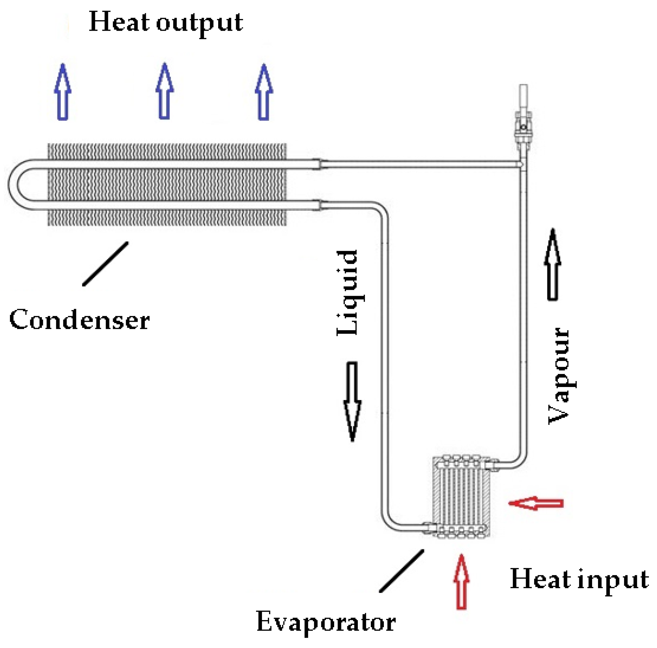
Figure 1 shows the parts of the gravity loop heat pipe. It can be oriented in a vertical or slightly inclined position. The name of the gravity heat pipe implies that it uses gravity to circulate the working medium when it operates [
10].
The heat pipe consists of a hermetically sealed circuit with a working medium at a precisely defined pressure. The heat transfer is based on a two-phase self-circulation of the heat transfer working medium. There is a condenser at the top and an evaporator at the bottom of the heat pipe. The distance between the evaporator and the condenser must be chosen with an adequate height difference. Inside the heat pipe, the working medium circulates from the evaporation to the condensation section in one direction in a closed loop. The liquid boils in the evaporator depending on the amount of supplied heat from the environment in which the heat pipe is located. The gaseous state of the working substance flows to the condenser, where it condenses to a liquid and releases the heat of evaporation. The working substance is cooled and, under the action of gravitational force, flows down into the evaporator again [
11]. The entire heat transfer process in a heat pipe is constantly repeated.
Gravity loop heat pipes have better thermal properties than active cooling systems because they use phase changes to transfer heat. The advantage is that the phase changes also occur at low mass flow rates, which increases the heat transfer coefficient. The selection of the working medium is flexible because there is no direct contact of the medium with the cooled component. The working medium is able to flow over relatively long distances without needing an external power supply, e.g., pump. Heat transfer over longer distances depends mainly on the thermodynamic properties of the working substance. The service life of the heat pipe is almost unlimited. This is due to the hermetically sealed design of the heat pipe without moving elements and the phase changes that are constantly repeating.
The simplicity and uniqueness of loop thermosiphons in relation to phase-change heat transfer encourage many kinds of research of new prototypes and applications of these exceptional devices. Scientists Palm and Khodabandeh were among the first to focus on the choice of working substance and its effect on performance and design in closed heat pipes. The research results were demonstrated by simulating heat transfer [
12]. Further research on two-phase heat transfer equipment has focused on various working substances used in the heat pipe system. Jouhara and his scientific team used the azeotropic working substance water-ethanol in a thermosiphon closed heat tube. The experiments were focused on the thermal properties of this mixture, the heat transfer performance, and the total thermal resistance. The results of the research proved the functionality and practical use of the proposed device in various applications even with an evaporator inclination from 0° to 90° [
13]. Zimmermann and Melo presented work focused on an experimental investigation of a carbon dioxide thermosiphon loop designed to fulfill the geometric and temperature requirements of a specific FPSC (free-piston Stirling cooler). Experiments were carried out varying the temperature difference between the heat source, i.e. air at the entrance of the evaporator and heat sink and the internal surface of the condenser, refrigerant charge, and evaporator airflow rate. The experimental results were explored using the thermal conductance concept applied to each heat exchanger and also to the whole loop. It was found that the loop was able to carry a maximum heat transfer rate of 514 W with a heat source-sink temperature difference of 11 °C [
14].
Specific applications of the use of heat pipes can be seen, e.g., in the industrial power industry for the cooling of nuclear reactors, gas turbine blades, rotors, and transformers, in the electronics for the cooling of power components of electronic equipment, and in the avionics, medicine and automotive industries [
15,
16,
17,
18,
19]. Heat pipes can also be used to reduce flue gas temperature in the flue gas tract of the heat source described by Čajová Kantová et al. [
20].
Heat pipes play an important role in increasing the cooling efficiency of data centers. Zhang et al. proposed an integrated system of mechanical refrigeration and thermosiphon (ISMT) by combining two independent loops, a mechanical refrigeration loop and a thermosiphon loop, with a three-fluid heat exchanger. The experimental results show that it has sufficient cooling capacity. The EER of the thermosiphon mode reaches 10.7 and 20.8, when the indoor and outdoor temperature difference is 10 °C and 20 °C, respectively, and the AEER of the ISMT is 12.6, which is much higher than traditional air conditioners (TAC) [
21]. In his publication, Jouhara analyzes the need for data center cooling, which is constantly increasing in energy and involves high costs. A simple cooling system based on heat pipes is designed which has the potential to save energy up to 75% [
22]. Another proposed system in this area is from Singh and his colleagues. This system is designed for cold areas below 0 °C because it is based on storing ice or cold water on a heat pipe. The proposed system can be used as a pre-cooler in data centers [
23]. Wang, Zhang, Li, and Luo used a combination of heat pipe processes and a cooling cycle to compress the vapor in their research to cool the data center. This resolved certain issues that arose during data center cooling processes, such as valve life and heat exchange areas [
24].
During further investigation of the cooling system based on the thermosiphon loop in the telecommunication box, an analytical model was developed by Chehade et al., which was subsequently tested experimentally. The designed device was tested at a maximum thermal load of 500 W and with various working fluids suitable for the space with electronic components. The cabinet space cooling system provided good results between the model and the experiment. Based on the results of the model, it was concluded that increasing the thermal efficiency of the system is possible by increasing the diameters of the pipes in the evaporating and condensing part of the heat pipe [
25]. Kim et al. developed a two-phase loop thermosiphon system for the B-ISDN telecommunications system and evaluated its performance both experimentally and by visualization techniques. The design of the proposed thermosiphon system was aimed to cool multichip modules (MCM) up to a heat flux of 8 W/cm
2. The results indicated that in the loop thermosiphon system, cooling heat flux is capable of 12 W/cm
2 with two condensers under the forced convection cooling of the condenser section with acetone or FC-87 as the working fluid [
26].
Lamaison and his research team introduced a cooling system using microchannel evaporators to cool processors. Increasing the diameter of the pipe in the heat pipe by 30% increased the heat flow by 10–60%. The results of the research served to improve the geometry of the designed device [
27]. Zhu and Yu proposed an ejector-assisted copper–water loop heat pipe with a flat evaporator (ELHP) for applications in electronic cooling and performed a simulation of its steady-state operation. The simulation results indicated that the ELHP can achieve a better performance than BLHP (basic loop heat pipe), which could be beneficial to the applications in electronic cooling [
28]. Khodabandeh investigated an advanced thermosiphon loop with an extended evaporator for the cooling of three parallel high-heat flux electronic components. The tested evaporators were made from small blocks of copper in which five vertical channels with a diameter of 1.5 mm and length of 14.6 mm were drilled. Tests were done with isobutane (R600a) at heat loads in the range of 10–90 W/cm
2 for each of the components with forced convection condenser cooling and with natural convection with heat loads of 10–70 W [
29].
Recent years of scientific experiments in research centers have proven the versatile use of heat pipes. Scientists have used heat pipes for cooling in various areas of electronics. The Sarno research team investigated the cooling of electronic components onboard aircraft using a gravitational heat pipe. The heat pipe cooling has two times more heat dissipation capacity than conventional cooling systems [
18]. Sun’s team designed a new cooling technology that combines the principle of phase change with natural cooling. This heat removal method was used to cool the telecommunications base stations. The measurement results show a 50% energy saving [
30]. Samba and colleagues performed an experimental measurement of the cooling of a small telecom cabinet. Cooling was provided by means of a gravitational heat pipe, to which air was supplied via fans. The working medium was n-pentane. Measurements have shown that by this method of cooling it is possible to transfer heat three times more than with fans [
6]. Tsoi and colleagues dealt with the cooling of telecommunication systems. They designed a new plate-type loop thermosiphon and examined its thermal performance under free and forced convective cooling conditions with both vertical and horizontal orientations [
31]. Sundaram and colleagues investigated a loop thermosiphon for cooling air inside a telecommunication cabinet. They proposed a model based on the combination of thermal and hydraulic management of a two-phase flow in the loop and experimentally tested a closed thermosiphon loop with different working fluids that could be used for electronic cooling [
32]. Miniature periodic two-phase thermosiphons with different evaporator sizes were also investigated for cooling electronic devices. A device with a larger volume transmitted higher heat loads of 110 W. Start-up phenomena were also observed, which proved to be smooth [
33]. Further research with miniaturized two-phase devices that are being developed for electronic device applications has been investigated with various working substances [
29,
34]. Chang and his team conducted a deeper study of the boiling phenomena and thermal properties of TPLT in electronics cooling. They investigated interfacial structures, boiling instability, heat transfer rates, as well as the effect of pressure on the phase change associated with heater performance and condenser thermal resistance. They concluded that at lower heat loads, the phenomena in the heat pipe are cyclic, unstable, and are characterized by longer onset times [
35]. Chehade and his research team investigated optimal TPLT loading in the range of 3% to 12%. Experimental studies revealed that of several working substance loading ratios, the optimal ratio was between 7% and 10%. The optimal cooling capacity, which was achieved by regulating the temperature and flow in TPLT to 5 °C and 0.7 L/min, was also studied [
15].
The introduction of the article pointed out the current research works on heat dissipation by the cooling systems based on the loop thermosiphon principle. Every study is exceptional with new proposals and applications, which brings new knowledge in this area. The subject of our research is the design of a dustproof passive cooling device for electrical cabinets operating on the principle of phase change of the working substance capable of transmitting high heat output of 500 to 2000 W. This is an unconventional method of cooling electrical enclosures and can bring many benefits. A novelty of the refrigeration equipment is a new evaporator which can enable more intensive heat transfer and high heating power up to 2000 W. In the following sections, the paper deals with the design and construction of the cooling device, experimental research of its cooling effect under different operating conditions, mathematical calculation equipment, and analysis of the results obtained.
6. Experimental Research
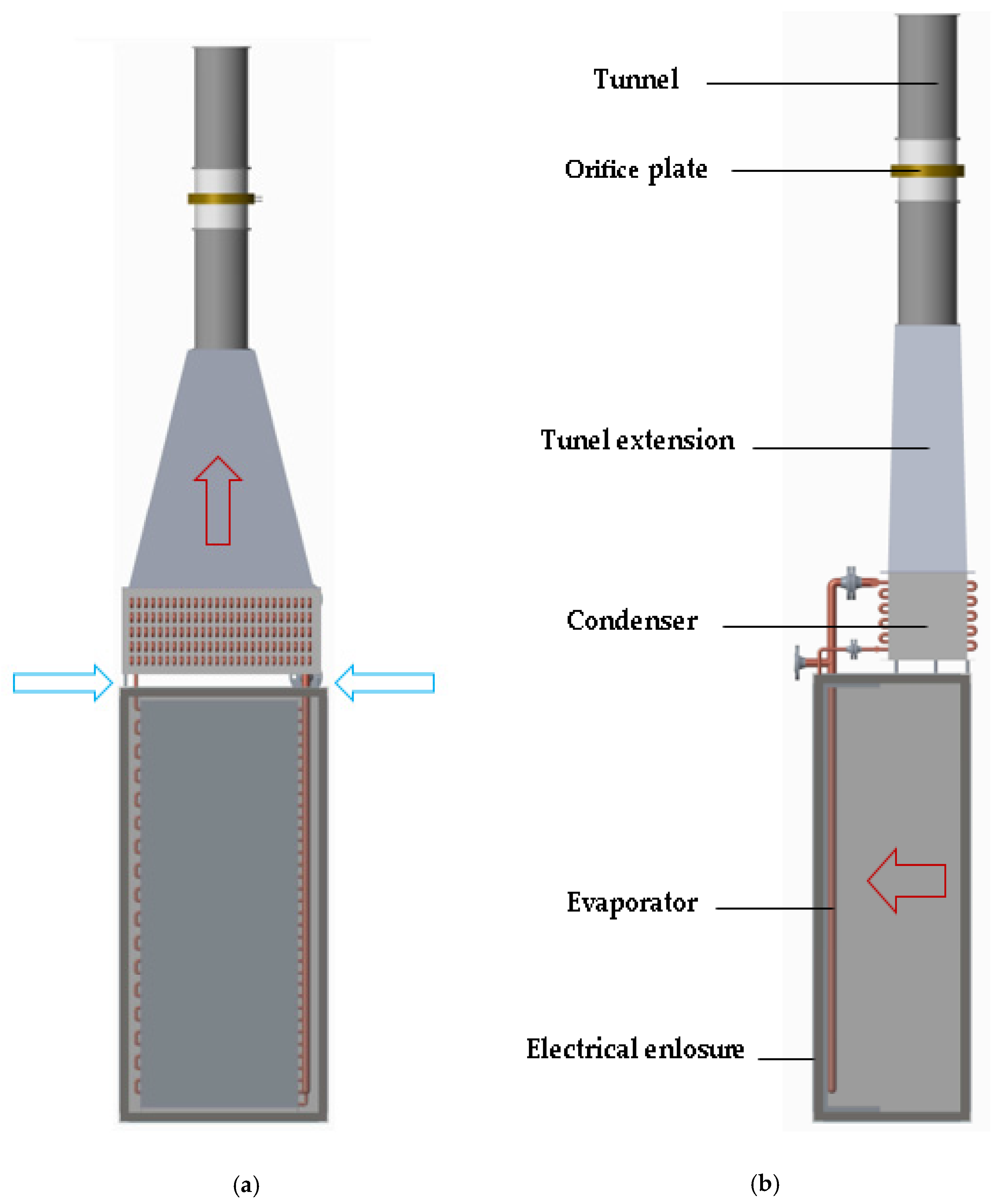
The task of the experimental research was to remove waste heat from the interior of the electrical enclosure and thus ensure suitable temperature conditions for electrical elements operation. The aim of the research was not to exceed a temperature of 60 °C inside the electric enclosure during the operation of the refrigeration equipment at a thermal load from 500 to 2000 W. Research works were performed on the experimental model of the electric enclosure at heat dissipations of 500 W, 750 W, 1000 W, 1500 W and 2000 W. Joule’s heat was simulated by using electrical heating elements placed on three levels on the top, in the middle, and on the bottom of the electric enclosure. The whole model of the experimental measuring device consists of an electrical enclosure with electrical heating elements, a cooling system, and a measuring part for thermal performance evaluation shown in
Figure 5 and
Figure 6.
The enclosure dimensions are 2000 × 850 × 600 mm. The arrows in
Figure 5 showed the airflow direction through the condenser and inside the electric enclosure. The evaporation part of the heat pipe was located in the interior of the electrical enclosure, where it receives heat, and the condensation part was placed above the electrical enclosure, where it dissipates heat to the ambient atmosphere. The distance between the evaporator and condenser is 30 mm. This configuration ensures the proper function of a gravitational loop heat pipe that uses the gravitational force for working substance circulation. Temperature sensors placed inside the electric enclosure give us data about interior temperature. The measuring part consists of a tunnel with temperature and pressure sensors, orifice plate and tunnel extension. The tunnel diameter is 160 mm, and the total length is 1000 mm. The orifice is placed in the middle of the tunnel. The diameter of the orifice throttle element is 60 mm. Mass airflow was measured in the tunnel. Temperature sensors placed under and above the condenser provided data to determine the heating power of the cooling device.
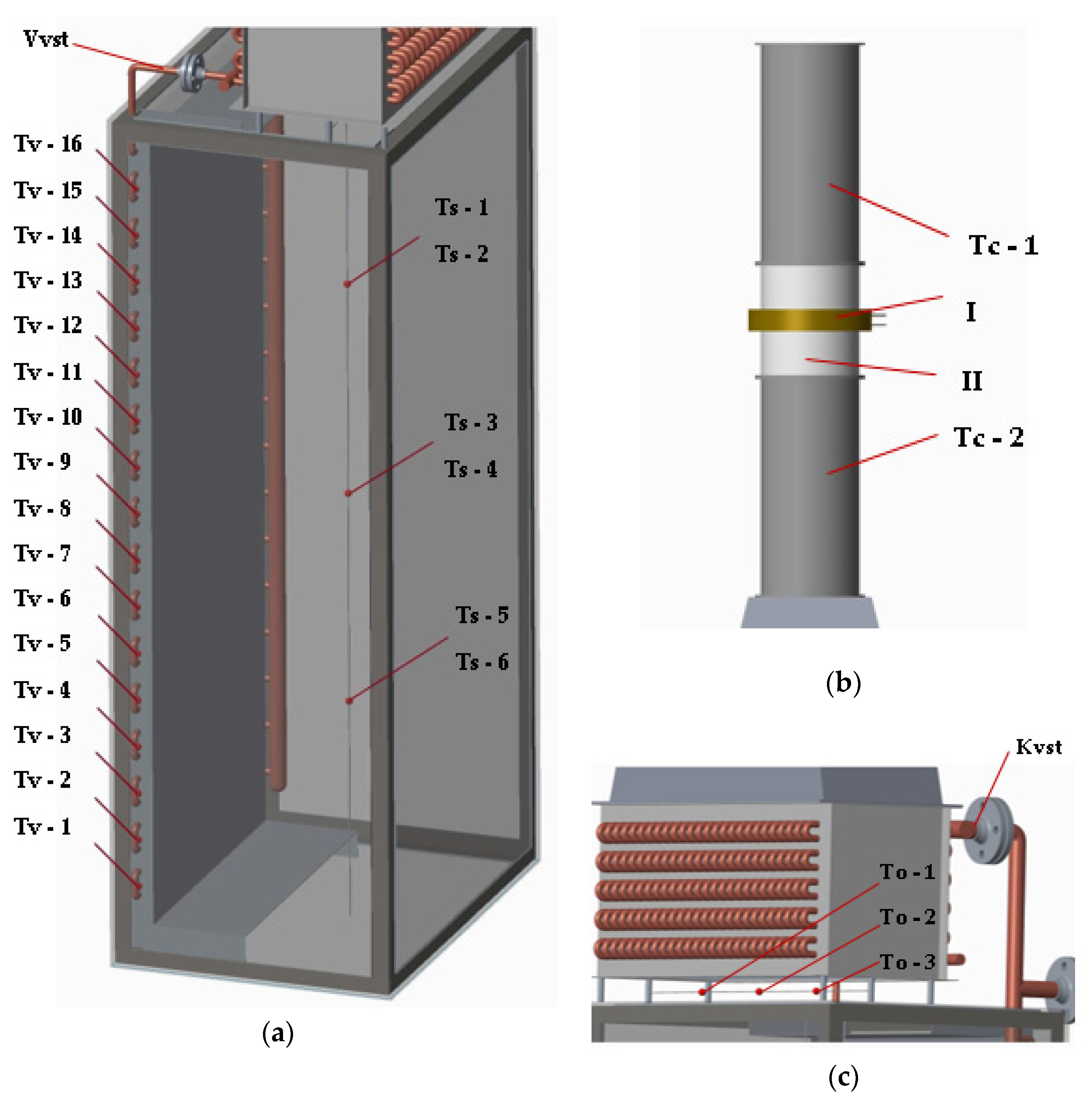
The layout of the temperature and pressure sensors is shown in
Figure 6. Inside the cabinet were temperature sensors located on the individual bends of the evaporator tubes, marked Tv-1 to Tv-16. Their task was to record the temperature, which provided information about the flow of the working medium in the evaporator. To control the interior temperature, sensors Ts-1 to Ts-6 were placed in the lower, middle and upper part of the cabinet. Temperature sensors marked Tk-1 to Tk-9 were placed on the condenser. They were used to control the flow of the working medium in the condenser. Temperature sensors To-1 to To-3 were placed below the condenser to record the temperature of the air entering the condenser. Two temperature sensors were placed in the tunnels in front of and behind the orifice plate to record the outlet temperature of the air from the condenser. Two pressure sensors were placed in front and behind the orifice throttle element for the determination of air velocity from pressure differences.
Before measuring, the whole heat pipe system was vacuumed to create an environment suitable for the phase transformation of the working substance. More intensive heat removal by the cooling device was provided by the active members like fans situated in the interior and exterior of the experimental measuring device. The task of the interior axial fans was to ensure uniform airflow directly to the evaporator. The external axial fan placed above the measuring part had the task of intaking air from the surroundings. Thus, heat flux was dissipated from the condenser, and it could be quantified. The cabinet was insulated from the outside by mineral wool thickness of 100 mm. The measurement was carried out at different volumes of water, the working medium. At each heat load, the evaporator was charged with a working medium of 20%, 40%, 60%, 80%, and 100%.
The experimental measurements were performed continuously every day for two weeks under the same conditions. Therefore, the results were not affected. The process of each measurement consisted of creating a vacuum, filling it with a working substance, heating the environment in the cabinet, stabilizing the temperature, and cooling the space and equipment. Figure 12 shows part of one measurement during temperature stabilization.
7. Mathematical Calculations
In this study, the calculation of the maximum heating power transferred by the cooling device from the interior of the electric enclosure to the surroundings was performed. The purpose of the mathematical calculation was to find a simple method to theoretically determine the heating power transferred through the phase change of the working substance which occurs inside the loop thermosiphon at loaded heat. The calculation was performed on the basis of the theoretical relationships of convective heat transfer inside the tube and on the outside of the finned tube. The calculation was based on the theory of thermal equilibrium of a heat pipe, where it is assumed that the amount of heat received in the evaporating part of the device is equal to the amount of heat dissipated by the condensing part to the surroundings. The computational relations were applied in ideal conditions. The values of the physical quantities used in the relationships were determined from the tables on the basis of the measured temperatures and pressures of the electrical enclosure interior, the outside environment, and the cooling device obtained during the measurement [
39,
40].
Due to the thermal balance, it was sufficient to create a model for calculating the total heating power removed by the cooling device for only one part of the device. The calculation was performed for the condenser part according to the equation:
Equation (2) depends on the inner surface of condenser tubes A1 (m2), average logarithmic temperature difference Δtavg (K) and overall heat transfer coefficient k (W/m2·K).
The overall heat transfer coefficient depends mainly on
α1 (W/m
2·K), the condensation heat transfer coefficient inside the tube, and
α2 (W/m
2·K), the convective heat transfer coefficient on the outside tube of the condenser, and is defined by the equation:
The calculation of heat transfer coefficients inside the pipe and on the surface depends on the density, thermal conductivity, dynamic and kinematic viscosity, surface tension, thermal conductivity, and latent heat. The efficiency of the fins and the size of the heat exchange surface are also important factors in heat exchange. The values of these physical quantities depend on temperature and change over time. It follows that the heat transfer coefficient is within a certain interval. The calculation of the condensation heat transfer coefficient inside the horizontal tubes of the condenser, in which the condensation of water vapour to the liquid took place, was performed according to the following equation [
41]:
where
g (m/s
2) is the gravitational acceleration,
lv (J/kg) is the latent heat of vaporization,
ρ (kg/m
3) is the air density,
λ (W/m·K) is the thermal conductivity,
ν (m
2/s) is the kinematic viscosity, Δ
θ (K) is the temperature difference of the tube wall and media, and
di (m) is the inner tube diameter. In the range of our investigated temperatures, the values of the heat transfer coefficient during condensation in the range of 330–520 W/m
2·K were calculated.
On the outside of the condenser tubes, heat was transferred to the surroundings by forced air convection due to the forced air flow from the external fan. The convection heat transfer coefficient on the outside of the tube was defined by the equation:
The heat transfer coefficient outside the tube mainly depend on αf (W/m2·K), the heat transfer coefficient, at the fin, where ηf (-) represents the fin effectiveness, Af (m2) indicates the fin area without the tube area, A2 (m2) represents the fin area and the corresponding section of the free tube, and ψ (-) is the correction factor. The convection heat transfer coefficient on the outside of the tube was in the range of 35–70 W/m2·K.
The heat transfer coefficient at the fin was calculated according to the equation
where
de (m) is the outside tube diameter,
λf (W/m·K) is the fin thermal conductivity,
ma (kg/s) is air mass flow,
Aa (m
2) is the air mass flow area,
μa (Pa·s) is the dynamic viscosity of air,
sf (m) is the distance between fins, and
hf (m) is the fin height.
The air mass flow area was calculated according to the equation
where
hc (m) is the condenser height,
wc (m) is the condenser width,
nc (-) is the number of the fin column in the condenser,
de (m) is the outside tube diameter,
lp (m) is the tube length,
hf (m) is the fin height,
sf (m) is the distance between fins, and
δf (m) is the fin width.
The inside tube area was calculated according to the equation
where
lp (m) is the tube length,
sf (m) is the distance between fins, and
A′
1 (m
2) is the internal tube area in the section between fins.
The internal tube area in the section between fins was calculated according to the equation
where
π (-) is the Ludolf number,
di (m) is the internal tube diameter, and
sf (m) is the distance between fins.
The fin area and the corresponding section of the free tube were calculated according to the equation
where
Af (m
2) is the fin area without the tube area,
π (-) is the Ludolf number,
de (m) is the outside tube diameter,
sf (m) is the distance between fins,
δf (m) is the fin width, and
lp (m) is the tube length.
The fin area without the tube area was calculated according to the equation
where
lc (m) is the condenser length,
hc (m) is the condenser height,
nt (-) is the total number of tubes,
π (-) is the Ludolf number,
de (m) is the outside tube diameter, and
δf (m) is the fin width.
The fin effectiveness was calculated according to the equation
where
m (-) is a constant and
hf (m) is the fin height.
where
αf (W/m
2·K) is the heat transfer coefficient on the fin,
λf (W/m·K) is the thermal conductance of the fin, and
δf (m) is the fin width.
8. Results and Discussion
The optimal state of cooling electrical enclosures by a cooling device was investigated depending on the volume of the working medium and the heat load. The measurement results are shown in
Figure 7,
Figure 8,
Figure 9,
Figure 10 and
Figure 11. The individual columns show the amount of dissipated heat calculated from the measured values of temperature and pressure in the measuring part and average temperature inside the electrical enclosure calculated from temperatures measured at the top, middle, and bottom.
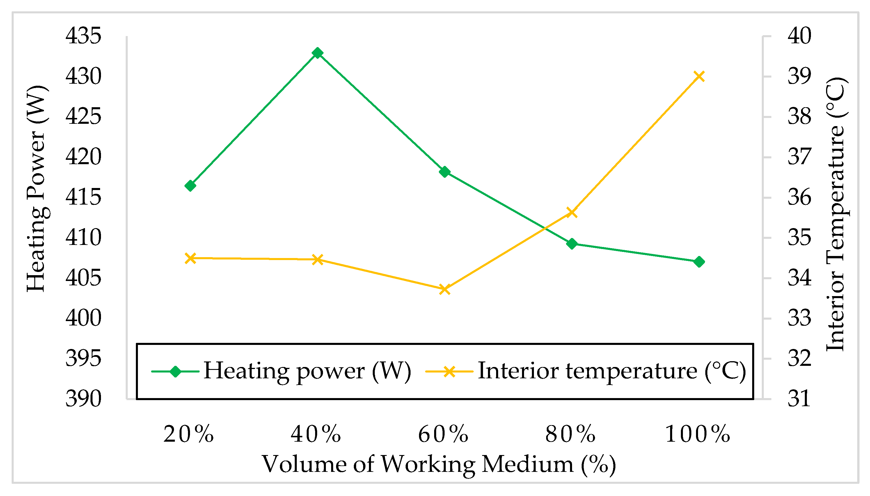
Figure 7 shows the results of heat transfer by means of a loop thermosiphon, the evaporating part of which was loaded with a simulated heat of 500 W from electrical resistance bodies. The analysis of the results showed that the cooling device removed heating power in the range of 433–407 W with an average value of 415 W and average operating temperature inside the electrical enclosure in the range of 33.5–39 °C at all investigated volumes of working medium. In terms of power dissipation to the environment, no dependence of the effect of the amount of working fluid in the evaporator was observed. From the point of view of the temperature in the interiors of the cabinet, it can be stated that at a volume of 100%, the temperature was significantly higher than at a volume of the working substance in the range of 20–80%. The best result was obtained with a working medium amount of 40% when the cooling system removed a heating power of 432 W from the electrical enclosure and the average operating temperature inside the electrical enclosure reached 34.5 °C.
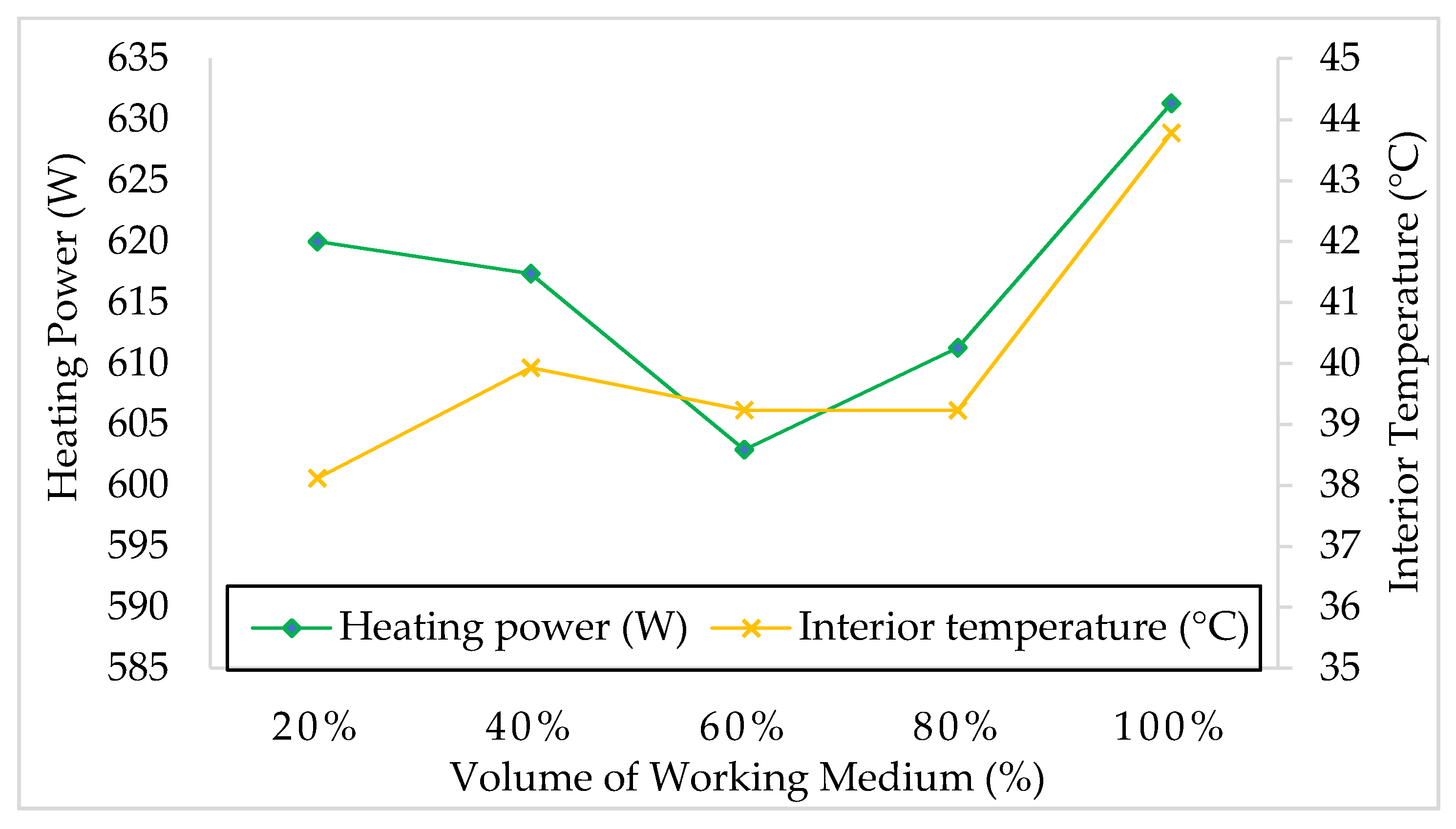
Figure 8 shows the results of heat transfer by means of a loop thermosiphon, the evaporating part of which was loaded with a simulated heat of 750 W from electrical resistance bodies. The analysis of the results showed that the cooling device removed heating power in the range of 615–630 W with an average value of 620 W and average operating temperature inside the electrical enclosure in range of 43–48 °C at all investigated volumes of working medium. In terms of power dissipation to the environment, no dependence of the effect of the amount of working fluid in the evaporator was observed. From the point of view of the temperature in the interiors of the cabinet, it can be stated that at a volume of 100%, the temperature was significantly higher than at a volume of the working substance in the range of 20–80%. The best result was obtained with a working medium amount of 20%, when the cooling system removed a heating power of 620 W from the electrical enclosure and the average operating temperature inside the electrical enclosure reached 38 °C.
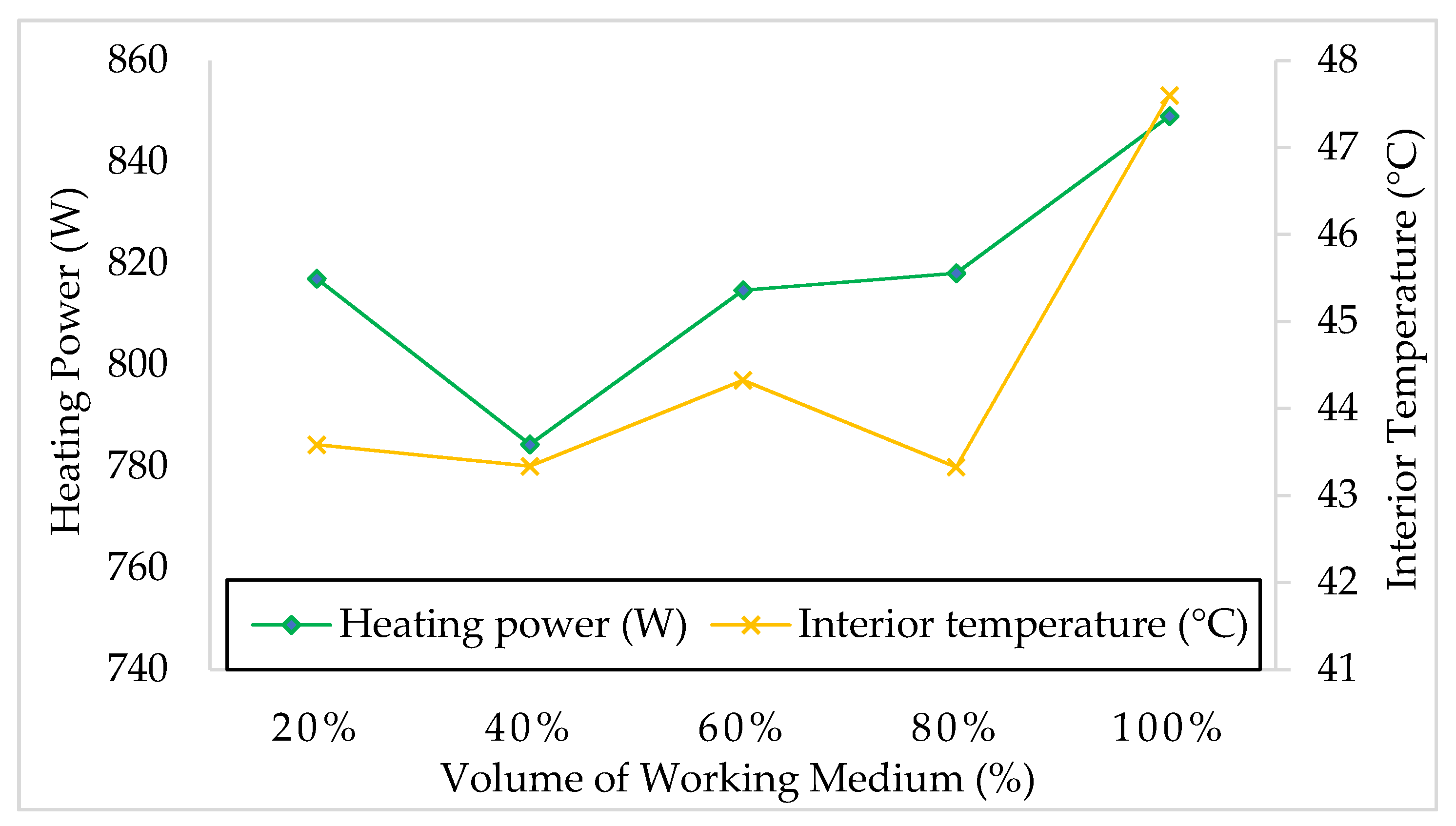
Figure 9 shows the results of heat transfer by means of a loop thermosiphon, the evaporating part of which was loaded with a simulated heat of 1000 W from electrical resistance bodies. The analysis of the results showed that the cooling device removed heating power in the range of 780–850 W with an average value of 817 W and an average operating temperature inside the electrical enclosure in the range of 43–48 °C at all investigated volumes of working medium. In terms of power dissipation to the environment, no dependence of the effect of the amount of working fluid in the evaporator was observed. From the point of view of the temperature in the interiors of the cabinet, it can be stated that at a volume of 100%, the temperature was significantly higher than at a volume of the working substance in the range of 20–80%. The best result was obtained with a working medium amount of 20%, when the cooling system removed a heating power of 818 W from the electrical enclosure and the average operating temperature inside the electrical enclosure reached 43 °C.
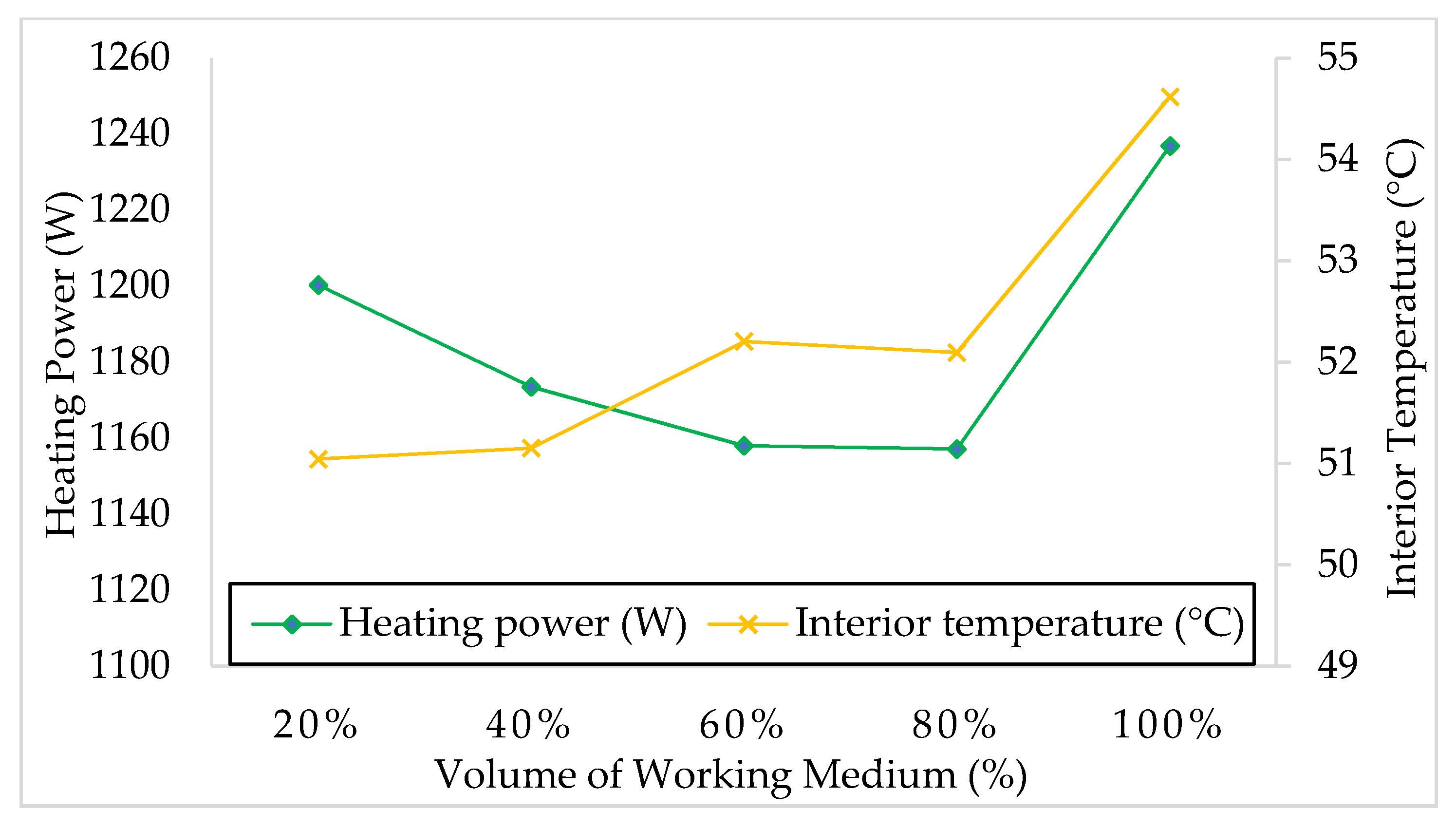
Figure 10 shows the results of heat transfer by means of a loop thermosiphon, the evaporating part of which was loaded with a simulated heat of 1500 W from electrical resistance bodies. The analysis of the results showed that the cooling device removed heating power in the range of 1157–1236 W with an average value of 1185 W and an average operating temperature inside the electrical enclosure in the range of 51–54.6 °C at all investigated volumes of working medium. In terms of power dissipation to the environment, no dependence of the effect of the amount of working fluid in the evaporator was observed. From the point of view of the temperature in the interiors of the cabinet, it can be stated that at a volume of 100%, the temperature was significantly higher than at a volume of the working substance in the range of 20–80%. The best result was obtained with a working medium amount of 20%, when the cooling system removed a heating power of 1200 W from the electrical enclosure and the average operating temperature inside the electrical enclosure reached 51 °C.
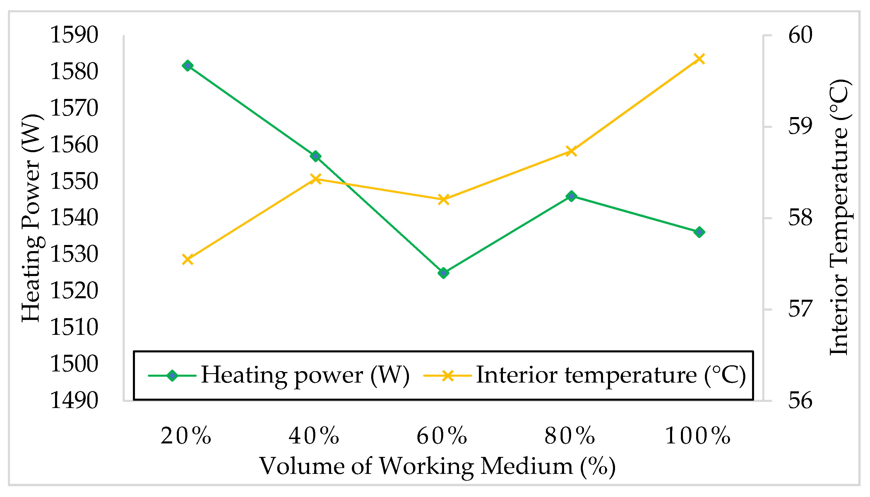
Figure 11 shows the results of heat transfer by means of a loop thermosiphon, the evaporating part of which was loaded with a simulated heat of 2000 W from electrical resistance bodies. The analysis of the results showed that the cooling device operates at all variants of working fluid volume very well when the cooling device was able to remove heating power in the range of 1525–1581 W with an average value of 1549 W and an average operating temperature inside the electrical enclosure in the range of 57.5–59.7 °C. In terms of power dissipation to the environment, the dependence of the effect of the amount of working fluid in the evaporator was observed. In this case, a lower heating power dissipation was observed at the working fluid volumes of 60–100% than at the volumes of 20–40%. From the point of view of the temperature in the interiors of the cabinet, there was a temperature increase that was observed at volumes of 60–100%. The best result was obtained with a working medium amount of 20%, when the cooling system removed 1582 W from the electrical enclosure heating power of and the average operating temperature inside the electrical enclosure reached 57.5 °C.
Overall, we can say that the proposed refrigeration equipment operated reliably under all tested conditions and achieved excellent results. Some dependence of the amount of working substance on the amount of heat removed was expected, but this was not clearly demonstrated. It is probable that the specially designed construction of the evaporator allows device uniform operation at different operating conditions. A slight decrease of the cooling effect was shown only in the case of a filling volume of 100%, when in all performed measurements, an increase in temperature was observed in the interiors of the cabinet, but not so much as to significantly affect the operation of electrical elements.
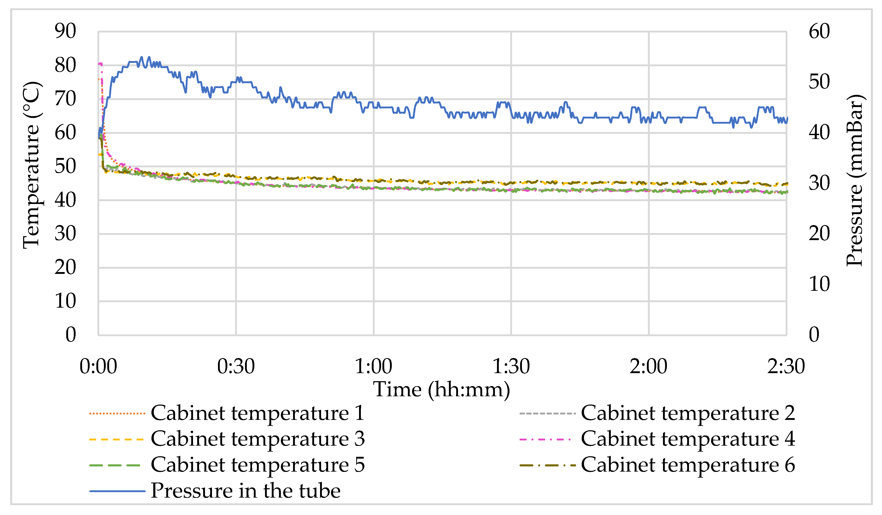
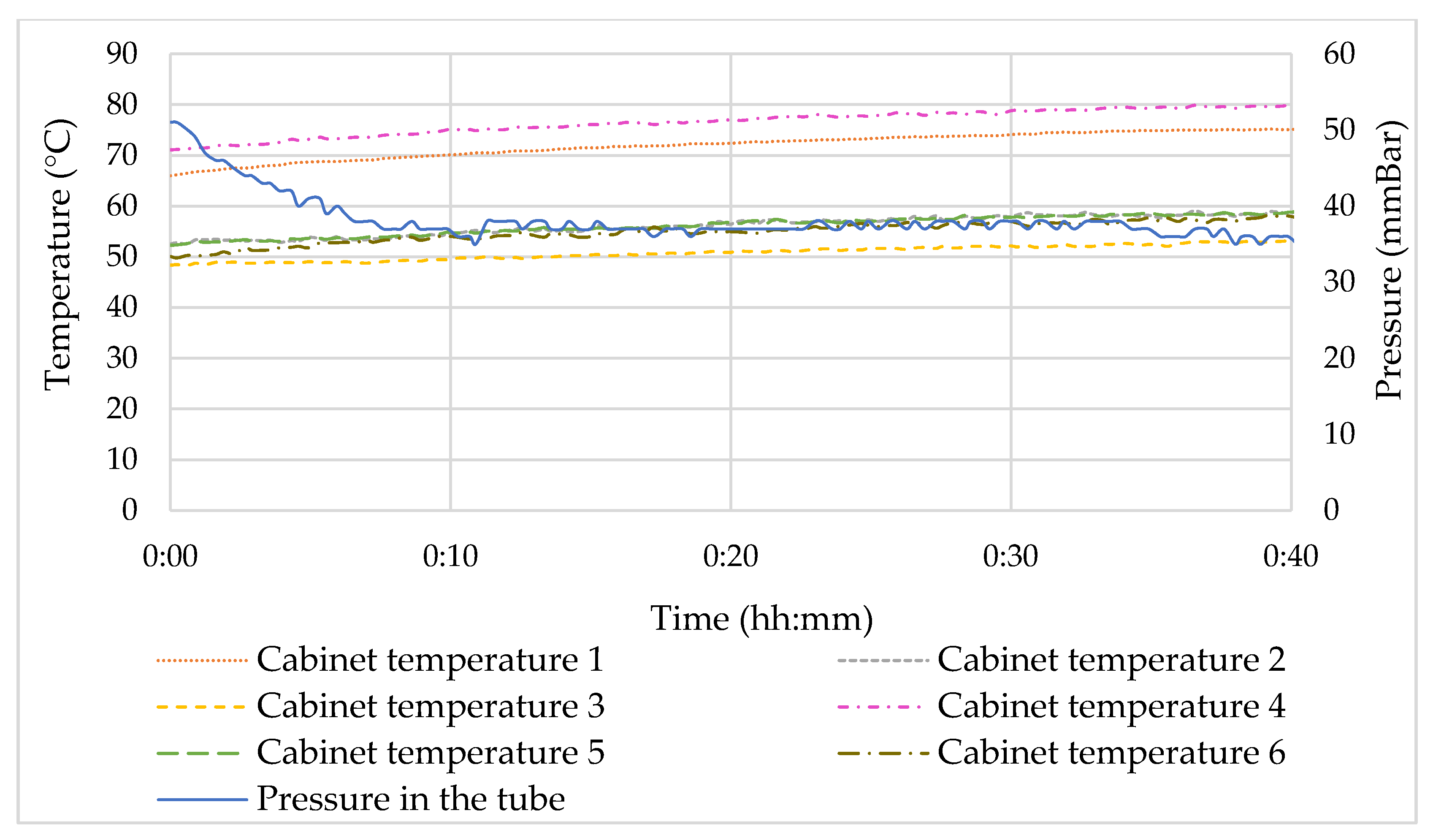
Figure 12 shows the temperatures and pressure courses inside the enclosure at the heat load of 1000 W, working fluid amount of 80%, and with fans turned on inside the enclosure. At the beginning of the measurement, the enclosure was heated to a temperature of about 80 °C by supplying the heat load of 2000 W. Then, the supplied heat was reduced to 1000 W, and the fans inside the cabinet, which are meant to the direct the flow towards the evaporator, were turned on. Then, it can be seen that the temperature inside the enclosure rapidly decreased in a few minutes to 50 °C and gradually decreased in time to approx. 45 °C. This indicates that the cooling device operates and cools the interior enclosure.
Figure 13 shows temperatures and pressure courses inside the enclosure at the heat load of 1000 W, working fluid amount of 80%, and with fans turned off inside the enclosure. This figure shows the part of the measurement during which the temperature inside the cabinet stabilized. It is seen that temperatures in some parts of the enclosure rose above 60 °C, but most temperatures were under 60 °C. This is a good sign that the cooling device is able to operate without the help of fans directing the airflow inside the enclosure.
The pressure profile inside the device throughout the experiments corresponds to the changing temperature conditions inside the cabinet. Before starting the measurement, the air was sucked out of the device, and subsequently, the device was filled with the working medium so as to guarantee the conditions of heat transfer by changing the phase of the working medium. The device worked independently without connection to an external vacuum pump. During the whole experiment, no air was sucked in from the exterior into the device, which can also be seen from the course of the pressures in
Figure 12 and
Figure 13.
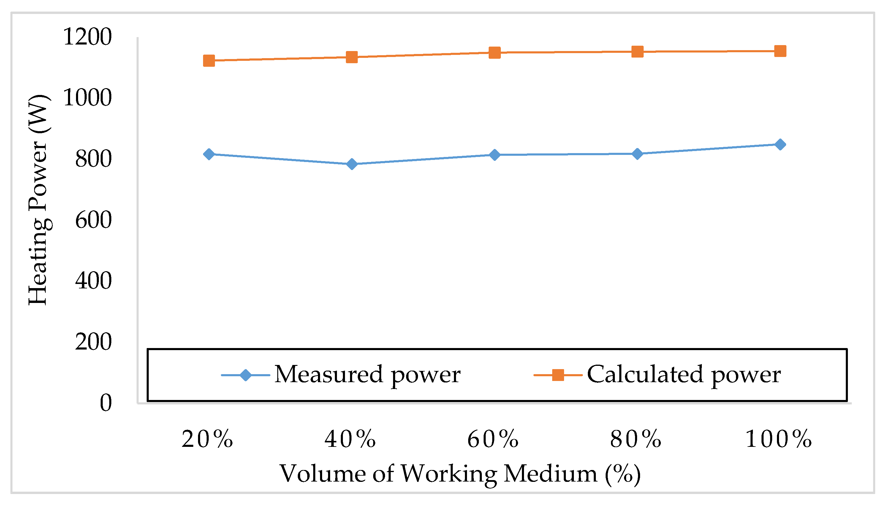
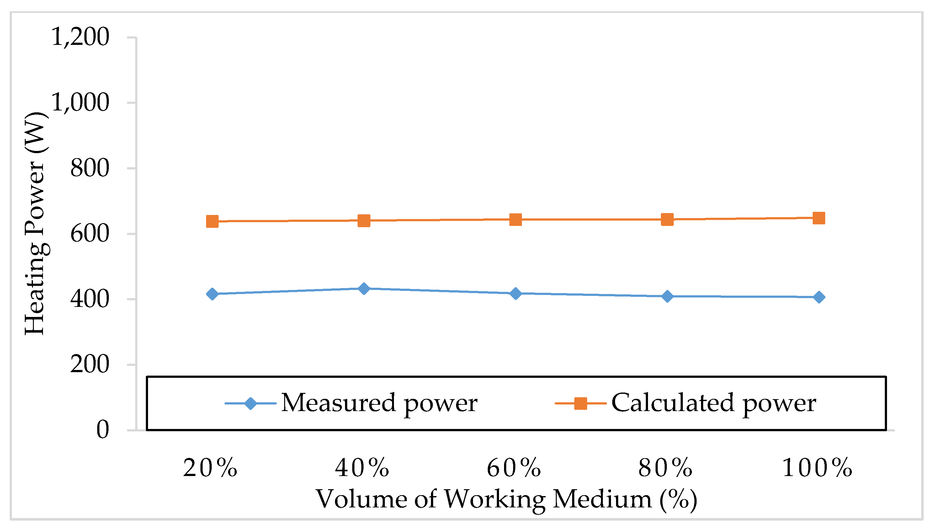
Figure 14 and
Figure 15 show a comparison of the results of the heating power transferred by cooling device obtained by measurement and by mathematical calculation at 1000 W and 500 W. Differences between the measured and calculated values of approximately about 25–30% can be seen. This demonstrates, therefore, that this simplified method considers idealized conditions. It often happens that the theoretical calculations differ from the real measured values, which are more decisive than the calculated ones. This calculation has shown the maximal theoretical heating power transferred by the cooling device at this setup and has additional indicative meaning for us.
The entire loop thermosiphon system is controlled automatically, according to the heat flow with low operating noise and minimal electricity consumption. Another method of cooling is refrigeration units and air conditioners, which, unlike heat pipes, are directly dependent on an external energy source [
42,
43]. The designed cooling system with a heat pipe is a simple and highly efficient device that can be adapted to various operations in a wide range of parameters. The current market also offers several products to choose from in the field of active cooling [
44]. The flow of the working substance in the heat pipe is ensured by gravity and the resulting buoyancy, which drives the flow of the two-phase refrigerant into the condenser. The height difference and density increase the potential of the driving force, which contributes to the increase in the flow and thus to the greater heat dissipation compared to the capillary heat pipe [
27]. The big advantage is the unattended and simple operation of the entire system. From a functional point of view, it works without any problems while maintaining unchanged initial conditions during the entire period of operation inside the tube. In terms of heat transfer, the loop thermosiphon is a simple, commonly used heat exchanger. The difference is in the phase change that takes place in the heat pipe and does not take place in the water-air or air-air heat exchangers [
7,
45].
On the other hand, the design of a heat pipe is more complex in terms of production in terms of material, time and finances. An important condition for the effective operation of the proposed system is to ensure the vacuum tightness of the heat pipe. The joints on the welds are very sensitive parts necessary to maintain pressure and are recommended to be inspected in detail. The operation of a loop thermosiphon depends on the placement of the individual parts in a vertical or slightly inclined position [
46].
The studies of cooling systems in an enclosed space with electrical elements mentioned in the introduction of this work are focused on passive heat dissipation using a heat pipe. This study is also focused on the passive cooling of the electrical cabinet with a new design of the heat exchangers of the cooling equipment, the operation of which is affected by the forced airflow from the fans. A similar problem of the loop thermosiphon was solved during the cooling of a telecommunication box. Various working substances and their physical properties on the effect of evaporation at 300 W, 400 W and 500 W have been investigated [
25]. In our research, we mainly observed the operating parameters in the interior of the cabinet, and the maximum amount of heat transferred was 2000 W.
Another study of a closed telecommunication cabinet also examined the flow inside the cabinet without other technologies. The results of experiments and numerical methods confirmed that cooling depends directly on the airflow inside the cabinet. The turbulent flow regime was investigated at speeds of 0.827 m/s, 0.704 m/s, and 0.757 m/s. The maximum heat load was 180.5 W [
17]. Axial fans with a speed of 2 m/s ensured the airflow in the electrical cabinet. Our experimental research included additional heat dissipation technology (a loop thermosiphon) compared to the telecommunication box. Forced convection has an effective effect on cooling in confined spaces, but in combination with a heat pipe device, the efficiency is much higher.
The experimental equipment of the cooling system is designed specifically for cooling a separately located closed electrical cabinet. This solution design ensures dust-free and trouble-free operation even with higher amounts of heat loss. In other research work with data centers [
7], cooling has been designed for larger spaces. In this case, the cooling was solved by mixing the air with the surrounding environment, or the circulation of air with the exterior was ensured. This method of cooling works efficiently but causes high amounts of dustiness on electrical components.


