Article

Dual-Conversion Microwave Down Converter for Nanosatellite Electronic Warfare Systems

1
Department of Engineering, University of Messina, 98166 Messina, Italy
2
Italspazio S.r.l., 95037 Catania, Italy
*
Authors to whom correspondence should be addressed.
Appl. Sci. 2022, 12(3), 1524; https://doi.org/10.3390/app12031524
Submission received: 28 December 2021 / Revised: 27 January 2022 / Accepted: 28 January 2022 / Published: 30 January 2022
(This article belongs to the Special Issue Advanced Research in Electronics: The Perspective of Women)

Abstract

:

Featured Application

The microwave down converter proposed in this work might be exploited in satellite systems, particularly for electronic warfare applications based on CubeSat systems. Due to the wide operating bandwidth, it can be used as the receiver stage of different applications, also taking advantage of its cost-effectiveness.

Abstract

In this work, a microwave down converter is proposed for nanosatellite electronic warfare applications. It provides high spurious suppression by exploiting a dual-conversion architecture and premium performance in terms of noise figure and linear dynamic range. The system design takes advantage of commercial off-the-shelf components, thus allowing for both fast and cost-effective prototyping, which are key requirements particularly concerning CubeSat systems. Since different military, commercial, radar and communication systems operate in the 2–18 GHz frequency band, the capability to integrate such kinds of receivers in CubeSats represents the new frontier of the electronic warfare systems. Moreover, due to the wide operating bandwidth, it can be successfully exploited as the receiver for different applications, e.g., satellite communication, radars, etc.

1. Introduction

Nowadays, military and defense departments pay particular attention to a wide variety of advanced technologies aimed at analyzing and manipulating the microwave frequency spectrum both for attack and defense purposes. The set of techniques and technologies employed to control and deny free access to the electromagnetic spectrum are commonly gathered under the name of electronic warfare (EW) [1,2,3].
Despite the great strides made by the researchers, the growing number of related scientific articles demonstrates that this is still a cutting-edge topic supported by a great scientific effort [4,5,6,7,8,9,10].
EW hardware architectures require wideband receivers to increase the extent of possible intercepted signals that are typically within the 2–18 GHz frequency bandwidth [11].
On the other hand, we are witnessing a disruptive increase of nanosatellite launches, e.g., CubeSat, with missions addressed not only by space agencies and commercial companies, but also by university teams [12,13,14,15,16].
CubeSats are a class of nanosatellites, built by complying with the standard dimensions of 10 cm × 10 cm × 10 cm. This standard “cube” represents a CubeSat Unit (U-), which typically weighs less than 1.33 Kg. Multiple units can be assembled in order to enhance the nanosatellite capabilities, e.g., a 6-U CubeSat can be created by using six standard units. By using standard dimensions, the designers can seize the opportunity to lunch their Cubesat by joining existing launch opportunities, thus keeping the launch cost low.
The great success of such a kind of compact and lightweight satellites can be attributed to their cost-effectiveness compared to larger size counterparts, enabled by the employment of commercial off-the-shelf (COTS) components, which are also easily accessible by university programs with limited budget. CubeSat projects might be completed within a very short time compared to traditional satellite schedules. They also represent great educational tools, e.g., for demonstrating technologies, novel techniques or scientific missions.
In this scenario, the possibility to integrate EW systems in CubeSats represents a great chance to fuel the research and development in this field.
In this contribution, a microwave down converter was designed for CubeSat EW applications. The complete down-conversion chain, including the double stage of local oscillator (LO) generation, was designed in a unique compact system that can be integrated in nanosatellites. Particular attention was paid to keep costs low and to the overall system reliability. The down converter involves a dual-conversion architecture to provide a severe reduction of both the number and level of spurious signals in the band of interest.
This task is addressed by first up-converting the received signal to a higher frequency, whereby the filtering stage might be more effective, and therefore by down-converting the filtered signal to baseband [17].
The system simulations exhibit spurious free dynamic range (SFDR) and linear dynamic range (LDR) equal to 40.2 dB and 52.6 dB, respectively, an overall noise figure (NF) lower than 3.2 dB and a flat conversion gain (CG) about equal to 28.3 dB.
Another interesting feature of the proposed down converter concerns the possibility to be exploited for different applications. Indeed, its wide operating bandwidth includes the operating frequencies of a great number of applications, e.g., satellite communication, radars, etc., where it can used as receiving stage [18,19,20,21,22,23].

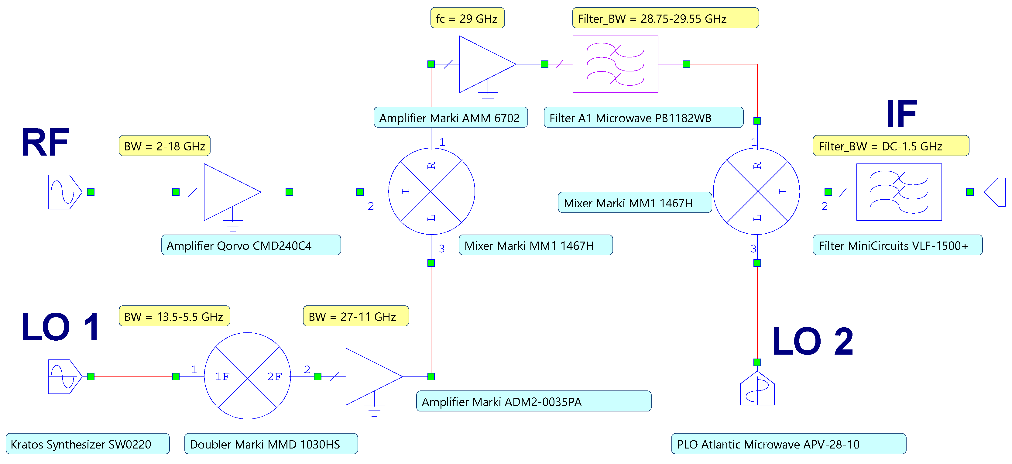
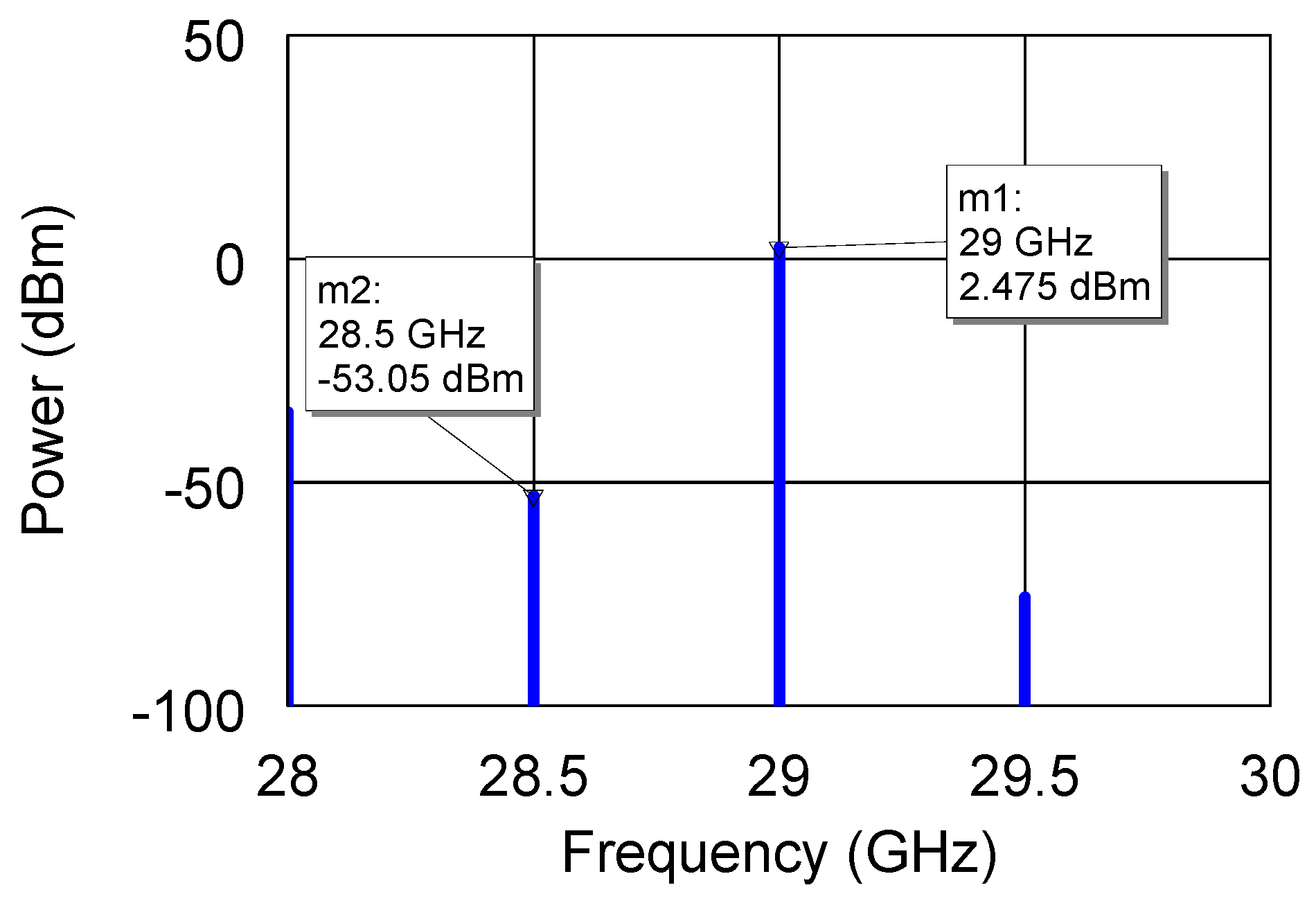
2. Circuit Design and Performance

The block diagram of the proposed microwave down converter is reported in Figure 1. The entire system was simulated within the Cadence AWR Microwave Office design environment.
The 2–18 GHz weak received signal is amplified by means of the CMD240C4 low-noise amplifier (LNA) by Qorvo, Inc. Thereafter, the amplified signal is applied to the MM1-1467H mixer by Marki Microwave, Inc., with the aim of performing the signal up-conversion to the 1 GHz bandwidth centered on 29 GHz. This task is accomplished by exploiting the mixer sum output, avoiding too high LO signals and, thus, the use of highly expensive components or multiple multiplication stages, which would dramatically increase the spurious number. The LO generation is addressed by injecting the 13.5–5.5 GHz signal generated by a SW0220 microwave synthesizer by Kratos Defense and Security Solutions, Inc. into a frequency doubler stage MMD 1030HS by Marki Microwave, Inc. The obtained 27–11 GHz signal multiplied by the 2 18 GHz input allows us to obtain a 29 GHz sum frequency with minimum spurious generation. Thereafter, the up-converted signal is amplified by the AMM 6702 amplifier by Marki Microwave, Inc. and filtered by means of the PB1182WB bandpass filter by A1 Microwave Ltd. within the bandwidth of about 1 GHz. The power spectrum of the signal after the filtering stage is reported in Figure 2, showing how the in-band spurious signals are severely reduced by the effective filtering. The test simulations were performed by considering a sample input frequency of 6 GHz, hence generating a 23 GHz LO signal.
It is worth noting that A1 Microwave Ltd. does not provide the scattering (S-) parameters for the PB1182WB filter; thus, its behavior was synthesized by designing an equivalent lumped-element network. In detail, the main filter parameters were reproduced by implementing a Chebyshev topology by means of the well-known insertion loss method, which allows for a high degree of control over the in-band and stopband amplitude and phase characteristics [24]. A nine-elements network was chosen in order to obtain the desired matching with the real filter performance. In Figure 3a, the filter schematic is shown, while the insertion loss and return loss of the filter are reported in Figure 3b. The excellent matching between the real and reproduced curves might be verified by observing the data reported in the datasheet of the component [25]. The values of the filter elements shown in the schematic are reported in Table 1.
Thereafter, the MM1-1467H mixer is employed in the down-conversion stage. To this purpose, the APV-28-10 phase-locked oscillator (PLO) by Atlantic Microwave Ltd. (Braintree, UK) generates the 28 GHz fixed frequency for the second LO input. Such a LO frequency is required to obtain the mixer difference frequency output centered at 1 GHz, which is finally filtered by the VLF-1500+ filter by MiniCircuits. The intermediate frequency (IF) signal might be easily processed by employing currently available analog-to-digital converters.
The IF signal spectrum at the output of the VLF-1500+ is reported in Figure 4, where the high spurious suppression is visible.
The down-converting chain components were carefully selected by paying great attention at the recommended LO power levels and at matching the dynamic range of adjacent components. The power budget of the down converter with line marks identifying the inter-stage output 1 dB compression points, OP1dB, is reported in Figure 5.
Due to the accurate identification of the required components, the proposed system exhibits the flat conversion gain shown in Figure 6.
Unfortunately, different models and data files of the components employed in the schematic are not furnished with noisy elements and parameters, respectively. As a consequence, it was not possible to simulate the noise behavior of the system, which was instead analytically estimated. In detail, the noise factor,   F c a s , of all the cascaded components in the path from the signal input up to the IF was computed by using the well-known Friis formula [24,26,27,28,29].
F c a s = F L N A + F M I X 1 G L N A + F A M P L 1 G L N A G M I X + F F I L T 1 1 G L N A G M I X G A M P L + + F M I X 1 G L N A G M I X G A M P L G F I L T 1 + F F I L T 2 1 G L N A G M I X G A M P L G F I L T 1 G M I X
where F L N A ,   F M I X , F A M P L , F F I L T 1 and F F I L T 2 are the noise factors of the CMD240C4 LNA, MM1-1467H mixer, AMM-6702 amplifier, PB1182WB filter and VLF-1500+ filter, respectively, whereas G L N A ,   G M I X ,   G A M P L   and   G F I L T 1 are the related gains. According to Equation (1), the NF of the down converter is equal to 3.18 dB.
It is worth noting that the noise figure is defined for a matched input source, and for a noise source equivalent to a matched load at the temperature T 0 = 290 . This hypothesis is reasonably verified for the employed components whose input/output impedance is very close to 50 Ω. Mismatches at the component ports would imply higher noise temperatures and thus increased noise figures.
Thereafter, the output noise power N 0   was calculated in Equarion (2) by assuming the receiving antenna is pointed toward the Earth, thus using the equivalent temperature of the receiving antenna T A   equal to T 0 [24].
N 0 = k T A + T c a s B G c a s
where   k is the Boltzmann constant of 1.38 × 10⁻²³ J K−1, B is the system bandwidth and T c a s and G c a s are the equivalent noise temperature and the gain of the overall system, as expressed in Equations (3) and (4), respectively.
T c a s = F c a s 1 T 0
G c a s = G L N A G M I X G A M P L G F I L T 1 G M I X G F I L T 2
The output noise power of –52.5 dBm was employed to calculate both the L D R   and the   S F D R by Equations (5) and (6), respectively.
L D R = O P 1 d B   c a s N 0
S F D R = 2 3 ( O I P 3   c a s N 0 ) S N R
where both the output 1 dB compression point,   O P 1 d B   c a s , and the output third-order intercept point, O I P 3   c a s , hereafter indicated as O P c a s , were calculated as:
O P c a s = 1 O P L N A G M I X G A M P L G F I L T 1 G M I X G F I L T 2 + 1 O P M I X G A M P L G F I L T 1 G M I X G F I L T 2 + + 1 O P A M P L G F I L T 1 G M I X G F I L T 2 + 1 O P F I L T 1 G M I X G F I L T 2 + 1 O P M I X G F I L T 2 + 1 O P F I L T 2 1
According to Equations (5) and (6), the computed values of SFDR and LDR are 40.2 dB and 52.6 dB, respectively.
A two-tone analysis was performed to graphically evaluate the intermodulation distortion (IMD) contributions vs. frequency and the O I P 3   c a s , as reported in Figure 7.
Although both the topics of satellite/nanosatellite technologies and electronic warfare systems separately achieved resounding interest in the literature, the possibility to integrate EW systems in CubeSats has not been investigated in depth. Moreover, a very limited effort has been devoted to the development of advanced down converter sections for this specific application and such a wide operating bandwidth. Filling the gap in research on very high operating bandwidth receivers in the literature represents one of the main purposes of the present article. As a result of a scientific literature investigation, the system performance was compared with recent similar results, as reported in Table 2. From Table 2, it is possible to note the superior performance of the proposed system in terms of noise figure, linear dynamic range and conversion gain, whereas in [30,31], the premium performance in terms of spurious free dynamic range was reported.
It is worth noting that previous works do not always share the same metric, due to different technologies and operating frequencies, thus making an accurate comparison quite challenging.
The system exhibits premium performance in terms of NF, LDR and conversion gain, whereas the next effort should be directed towards improving the SFDR.

3. Conclusions

In this contribution, the performance of a microwave down converter for nanosatellite electronic warfare applications is reported. It exploits a dual-conversion architecture showing noise figure, linear dynamic range and conversion gain equal to 3.2 dB, 52.6 dB and 28.3 dB, respectively. The system employs COTS components and is expected to be integrated aboard a CubeSat system. The main features are highlighted and compared to the existing more recent literature.

Author Contributions

Conceptualization, E.C., R.C. and P.V.; methodology, E.C. and R.C.; software, E.C.; validation, E.C., R.C., P.V. and E.C; formal analysis, A.C.; investigation, E.C., R.C. and P.V.; resources, A.C.; data curation, E.C.; writing—original draft preparation, E.C. and A.C.; writing—review and editing, E.C. and A.C.; project administration, P.V. All authors have read and agreed to the published version of the manuscript.

Funding

This research received no external funding.

Acknowledgments

This work was supported by the Italspazio Research Department in the framework of a collaboration between the University of Messina, Messina, Italy, and Italspazio S.r.l., Catania, Italy.

Conflicts of Interest

The authors declare no conflict of interest.

References

  1. Sharma, P.; Sarma, K.K.; Mastorakis, N.E. Artificial intelligence aided electronic warfare systems- recent trends and evolving applications. IEEE Access 2020, 8, 224761–224780. [Google Scholar] [CrossRef]
  2. Chen, C.; Wang, S.; Li, L.; Ke, S.; Wang, C.; Bu, X. Intelligent covert satellite communication for military robot swarm. IEEE Access 2020, 8, 5363–5382. [Google Scholar] [CrossRef]
  3. El Hadri, D.; Zugari, A.; Zakriti, A.; El Ouahabi, M.; Taouzari, M. A compact triple band antenna for military satellite communication, radar and fifth generation applications. Adv. Electromagn. 2020, 9, 66–73. [Google Scholar] [CrossRef]
  4. Jeon, Y.; Bang, S. Front-end module of 18–40 GHz ultra-wideband receiver for Electronic Warfare system. J. Electromagn. Eng. Sci. 2018, 18, 188–198. [Google Scholar] [CrossRef] [Green Version]
  5. Salari, S.; Kim, I.; Chan, F.; Rajan, S. Blind compressive-sensing-based electronic warfare receiver IEEE Trans. Aerosp. Electron. Syst. 2017, 53, 2014–2030. [Google Scholar] [CrossRef]
  6. Kumari, A.N.M.; Varughese, S.; Venkatesh Rao, P. Miniaturized ultra-wideband printed dipole array for electronic warfare applications in unmanned aerial vehicle systems. Microw. Opt. Technol. Lett. 2020, 62, 3601–3610. [Google Scholar] [CrossRef]
  7. Ghelfi, P.; Onori, D.; Laghezza, F.; Scotti, F.; Bogoni, A.; Albertoni, A.; Tafuto, A. An RF scanning receiver based on photonics for electronic warfare applications. In Proceedings of the 2015 12th European Radar Conference, Paris, France, 9–11 September 2015. [Google Scholar]
  8. Bhavsar, M.L.; Kumar, P.; Chaturvedi, I.; Srivastava, P.; Singh, D.K.; Bhattacharya, A. LTCC based multi chip modules at C-band and Ka-band for satellite payloads. In Proceedings of the IEEE MTT-S International Microwave and RF Conference, Ahmedabad, India, 11–13 December 2017. [Google Scholar]
  9. Rodio, L.; Schena, V.; Grande, M.; Calò, G.; D’Orazio, A. Microwave-photonic technologies for satellite telecommunication payloads: A focus on photonic RF frequency conversion. In Proceedings of the IEEE 8th International Workshop on Metrology for AeroSpace, Naples, Italy, 23–25 June 2021. [Google Scholar]
  10. Lee, K.-T.; Meng, C.; Wu, Y.-F.; Huang, G.-W. Ku-band single-voltage-supply downconverter using 0.15 µm pHEMT process. In Proceedings of the Asia-Pacific Microwave Conference, Delhi, India, 5–9 December 2016. [Google Scholar]
  11. Bannister, D.C.; Zelley, C.A.; Barnes, A.R. A 2–18 GHz wideband high dynamic range receiver MMIC. In Proceedings of the IEEE Radio Frequency Integrated Circuits Symposium, Seattle, WA, USA, 2–4 June 2002. [Google Scholar]
  12. Tang, Y.-F.; Yu, X.-H. The effectiveness evaluation of nano-satellites used in military operations. In Proceedings of the International Conference on Mechatronic Sciences, Electric Engineering and Computer, Shenyang, China, 20–22 December 2013. [Google Scholar]
  13. Granger, R.; Dalgleish, B. Developing nano/micro satellite technology for government and military applications. In Proceedings of the Milsatcoms Conference, London, UK, 3–5 November 2015. [Google Scholar]
  14. Persicom, A.R.; Clementemm, C.; Soraghanm, J. CubeSAT based bistatic passive radar for ballistic missile defence: Feasibility study. In Proceedings of the International Conference on Radar Systems, Belfast, UK, 23–26 October 2017. [Google Scholar]
  15. Raissouni, N.; El Adib, S.; Sobrino, J.A.; Ben Achhab, N.; Chahboun, A.; Azyat, A.; Lahraoua, M. Towards LST split-window algorithm FPGA implementation for CubeSats on-board computations purposes. Int. J. Remote Sens. 2019, 40, 1–16. [Google Scholar] [CrossRef]
  16. Marzioli, P.; Frezza, L.; Amadio, D.; Hossein, S.H.; Pancalli, M.G.; Picci, N.; Vestito, E.; Piergentili, F.; Celesti, P.; Curiano, F.; et al. Hands-on education through nano-satellites development: Past, current and future projects at Sapienza S5Lab. In Proceedings of the 7th International Workshop on Metrology for AeroSpace, Pisa, Italy, 22–24 June 2020. [Google Scholar]
  17. Simsek, A.; Kim, S.-K.; Ahmed, A.S.H.; Maurer, R.; Urteaga, M.; Rodwell, M.J. A dual-conversion front-end with a W-band first intermediate frequency for 1–30 GHz reconfigurable transceivers. In Proceedings of the IEEE Radio and Wireless Symposium, Orlando, FL, USA, 20–23 January 2019. [Google Scholar]
  18. Morishita, Y.; Hanssen, R.F. Temporal decorrelation in L-, C-, and X-band satellite radar interferometry for pasture on drained peat soils. IEEE Trans. Geosci. Remote Sens. 2015, 53, 1096–1104. [Google Scholar] [CrossRef]
  19. Tings, B.; Pleskachevsky, A.; Velotto, D.; Jacobsen, S. Extension of ship wake detectability model for non-linear influences of parameters using satellite based X-band synthetic aperture radar. Remote Sens. 2019, 11, 563. [Google Scholar] [CrossRef] [Green Version]
  20. Cardillo, E.; Caddemi, A. A novel approach for crosstalk minimization in FMCW radars. Electron. Lett. 2017, 53, 1379–1381. [Google Scholar] [CrossRef]
  21. Manfredi, G.; Hinostroza, I.D.S.; Menelle, M.; Saillant, S.; Ovarlez, J.-P.; Thirion-Lefevre, L. Measurements and analysis of the Doppler signature of a human moving within the forest in UHF-band. Remote Sens. 2021, 13, 423. [Google Scholar] [CrossRef]
  22. Cardillo, E.; Li, C.; Caddemi, A. Embedded heating, ventilation, and air-conditioning control systems: From traditional technologies toward radar advanced sensing. Rev. Sci. Instrum. 2021, 92, 061501. [Google Scholar] [CrossRef] [PubMed]
  23. Cardillo, E.; Li, C.; Caddemi, A. Millimeter-wave radar cane: A blind people aid with moving human recognition capabilities. IEEE J. Electromagn. RF Microw. Med. Biol. 2022, 1–8. [Google Scholar] [CrossRef]
  24. Pozar, D.M. Microwave Engineering; Wiley: Hoboken, NJ, USA, 2012. [Google Scholar]
  25. A1 Microwave, PB1182WB K-Band Satcom Upconverter Filter, Rev. 26 August 2017. Available online: https://www.a1microwave.com/pdfs/DS_Ku_band_TX_upconverter_PB1198WB_Iss_03_Aug_2017.pdf (accessed on 21 July 2021).
  26. Caddemi, A.; Cardillo, E.; Crupi, G. Equivalent-circuit based modeling of the scattering and noise parameters for multi-finger GaAs pHEMTs. Int. J. Numer. Model. 2020, 33, 1–7. [Google Scholar] [CrossRef]
  27. Caddemi, A.; Boglione, L.; Cardillo, E.; Crupi, G.; Roussos, J. Cross-laboratory experimental validation of a tuner-less technique for the microwave noise parameters extraction. IEEE Trans. Microw. Theory Techn. 2021, 69, 1733–1739. [Google Scholar] [CrossRef]
  28. Caddemi, A.; Cardillo, E.; Patanè, S.; Triolo, C. An accurate experimental investigation of an optical sensing microwave amplifier. IEEE Sens. J. 2018, 18, 9214–9221. [Google Scholar] [CrossRef]
  29. Caddemi, A.; Cardillo, E.; Crupi, G. Comparative analysis of microwave low-noise amplifiers under laser illumination. Microw. Opt. Technol. Lett. 2021, 58, 2437–2443. [Google Scholar] [CrossRef]
  30. Zhang, D.; Li, L.; Guan, F.; Wu, Z.; Wang, H.; Chen, K. Design of a 2–18 GHz downconverter with amplitude and phase consistency. In Proceedings of the IEEE MTT-S International Wireless Symposium, Guangzhou, China, 19–22 May 2019. [Google Scholar]
  31. Gabrielli, G.; Gualano, R.A.; Aureliano Imparato, E.B.; Mitrano, C.; Pietrobono, M.; Cirella, V. Spurious-free ultra-wideband downconveter in 3U size for EW system. In Proceedings of the Photonics & Electromagnetics Research Symposium—Spring, Rome, Italy, 17–20 June 2019. [Google Scholar]
  32. Van de Beek, R.; Bergervoet, J.; Kundur, H.; Leenaerts, D.; Van der Weide, G. A 0. 6-to-10GHz receiver front-end in 45 nm CMOS. In Proceedings of the IEEE International Solid-State Circuits Conference—Digest of Technical Papers, San Francisco, CA, USA, 5–9 February 2008. [Google Scholar]
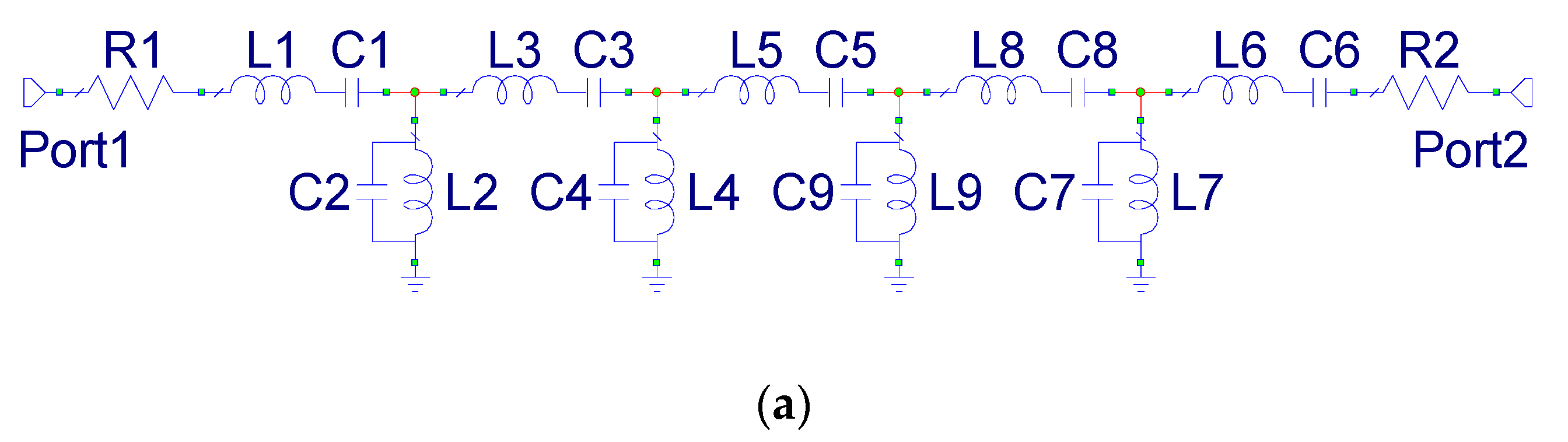
Figure 1. Block diagram of the dual–conversion microwave down converter.
Applsci 12 01524 g001
Figure 2. Power spectrum of the up-converted signal after the PB1182WB filter.
Applsci 12 01524 g002
Figure 3. (a) Schematic and (b) insertion loss (blue solid line) and return loss (red dotted line) of the simulated PB1182WB filter.
Applsci 12 01524 g003aApplsci 12 01524 g003b
Figure 4. Power spectrum of the down-converted IF signal after the VLF-1500+ filter.
Applsci 12 01524 g004
Figure 5. Power budget of the down converter with OP1dB line marks.
Applsci 12 01524 g005
Figure 6. Conversion gain of the down converter.
Applsci 12 01524 g006
Figure 7. (a) IMD vs. frequency and (b) O I P 3   c a s .
Applsci 12 01524 g007
Table 1. Values of the simulated filter elements.
Element TypeElement IDValue
ResistorR1, R22 Ω
InductorL1, L69.19 nH
InductorL2, L78.07 pH
InductorL3, L815.3 nH
InductorL4, L97.33 pH
InductorL515.74 nH
CapacitorC1, C63.24 fF
CapacitorC2, C73.70 pF
CapacitorC3, C81.95 fF
CapacitorC4, C94.07 pF
CapacitorC51.90 fF
Table 2. Performance comparison with recent works.
[30][31][32][17]This Work
TechnologyModulesModulesMMICMMICModules
Frequency (GHz)2–182–180.6–101–302–18
Conversion gain (dB)ND2814(−4)–(−7)28.3
NF (dB)5.5ND74–73.2
LDR (dB)43NDNDND52.6
SFDR (dB)5055ND2040.2
Publisher’s Note: MDPI stays neutral with regard to jurisdictional claims in published maps and institutional affiliations.

