Article

2D Winograd CNN Chip for COVID-19 and Pneumonia Detection

Department of Electronic Engineering, National Taipei University of Technology, Taipei 10608, Taiwan
*
Author to whom correspondence should be addressed.
Appl. Sci. 2022, 12(24), 12891; https://doi.org/10.3390/app122412891
Submission received: 29 October 2022 / Revised: 10 December 2022 / Accepted: 14 December 2022 / Published: 15 December 2022

Abstract

:
In this paper, a two-dimensional Winograd CNN (Convolutional Neural Network) chip for COVID-19 and pneumonia detection is proposed. In light of the COVID-19 pandemic, many studies have led to a dramatic increase in the effects of the virus on the lungs. Some studies have also pointed out that the clinical application of deep learning in the medical field is also increasing, and it is also pointed out that the radiation impact of CT exposure is more serious than that of X-ray films and that CT exposure is not suitable for viral pneumonia. This study will analyze the results of X-rays trained using CNN architecture and convolutional using Winograd. This research will also set up a popular model architecture to realize four kinds of grayscale image prediction to verify the actual prediction effect on this data. The experimental data is mainly composed of chest X-rays of four different types of grayscales as input material. Among them, the research method of this experiment is to design the basic CNN operation structure of the chip and apply the Winograd calculus method to the convolutional operation. Finally, according to the TSMC 0.18 μm process, the actual chip is produced, and each step is verified to ensure the correctness of the circuit. The experimental results prove that the accuracy of our proposed method reaches 87.87%, and the precision reaches 88.48%. This proves that our proposed method has an excellent recognition rate.

1. Introduction

1.1. Background

The pandemic Coronavirus disease 2019 (COVID-19) virus is related to the severe acute respiratory syndrome coronavirus 2 (SARS-CoV-2) coronavirus that causes severe acute respiratory syndrome, but compared to the following, the observation of COVID-19 is significantly more extensive than that of SARS-CoV-2. Increased attention to pulmonary symptoms has also led to a relative increase in research into the virus’ effects on pregnant women [1,2]. Observing the impact of the spread of the coronavirus is one of the most studied research questions since the pandemic began [1,2,3]. In this regard, it is known that many countries will have more research on the impact of the virus on the lungs [3].
COVID-19 was first detected in Wuhan, China, in 2019 [4]. Regmi presented “the scenario of COVID-19 pandemics in the top ten worst-affected countries” [4]. The top ten countries affected by COVID-19 are the USA, Brazil, Russia, Spain, the UK, Italy, France, Germany, Turkey, and Iran [4]. People are not only dying from physical infection with the COVID-19 virus but also dying from mental illness caused by long-term stress [5]. COVID-19 causes not only physical effects but also psychological damage [5].
Studies have shown that when looking at the effects of the virus on the lungs, using Computed Tomography (CT) images is less effective than looking at chest X-rays, which are more expensive and have higher radiation than chest X-rays [6]. It can be seen from this that if one wants to observe the effect of virality on the lungs, especially the symptoms caused by ribonucleic acid (RNA) viruses in vivo, CT is not suitable in reality [6,7]. COVID-19 has caused a pandemic with a significant increase in the number of cases, which was uncommon before the virus caused chest pneumonia, but now the opposite is evident. Now, general chest radiographs can be used to identify this viral infection, so the use of CT is also gradually decreasing. In the detection and diagnosis of multiple medical fields, computer-aided diagnosis combined with machine learning (ML)/deep learning (DL) systems have been applied in clinical medicine, and some artificial intelligence methods have been adopted to improve their diagnostic recognition and accuracy [8,9]. In addition, Sitaula [10] proposes a novel “attention-based deep learning model using the attention module with VGG-16” [10]. This forward-looking method uses the attention module to capture the spatial relationship between the ROIs in CXR images and achieves excellent results [10].

1.2. Research Goal

Generally speaking, chest X-rays are often used for diagnosis to observe the impact of the virus on the lungs, and the recognition of chest X-rays can be regarded as a grayscale picture in computer vision [11]. Algorithms play an important role in machine learning/deep learning systems and are to be used to train AI diagnostic and recognition capabilities and to ensure that training results can be achieved within a limited time for medical image analysis [8,9,12]. Because this medical image is a grayscale image, according to the analysis of the model, the Convolutional Neural Networks (CNNs) model has a greater advantage than other models in image analysis [6]. This research will enhance its computational power in the convolutional layers of CNNs models, showing the advantages of their algorithms on physical circuits. Although the CNNs model has relatively high advantages over other models in image analysis, this study will also analyze a variety of different models to show the model with the most advantages and reliability.
According to much literature, although there are many kinds of accelerated convolutional, the most simple and effective implementation method is still Winograd [13,14,15,16,17]. Therefore, two-dimensional Winograd convolution algorithms using the FPGA platform are proposed [18,19,20]. This research will look forward to applying Winograd’s algorithm to one layer of convolutional neural network chips and conducting chip-related experiments on it. According to the previous literature [21], this research will analyze different viewpoints on the overall content and redesign different processes, apply the Winograd algorithm to a layer of convolutional neural network chips, and conduct more chip-related experiments on it. In this study, it is expected that the advantages and disadvantages of Winograd will be clearly understood in practical circuits. The technical specification testing standard method of the low-power 0.18 μm TSMC process used in this experiment will also be used to verify the reliability of the circuit [22,23,24,25].

2. Materials and Methods

According to the design process in Figure 1, we designed the basic operation part first. This part was designed concerning the general Convolutional Neural Network (CNN) operation method. After the basic part was designed, the Winograd calculation method was used here. Of course, in the process and steps of each design, their accuracy was verified one by one to ensure that the overall circuit would not affect the operation of the entity due to some factors. After that, the model simulation and verification of CNNs were carried out to ensure the accuracy of the experiment, and the model was analyzed by comparing it with other related literature.

2.1. Materials

Test Data

While searching for material, we found open-source material available in the literature. According to related research and experiments in other literature, the data of this literature are quite reliable [26,27]. Therefore, the model validation data of this experiment was based on the data recorded in these files as a reliable data basis. A total of 16 samples are here, and these samples were used for the training, testing, and validation data used in this experimental model, and the analysis of the model began here.

2.2. Methods

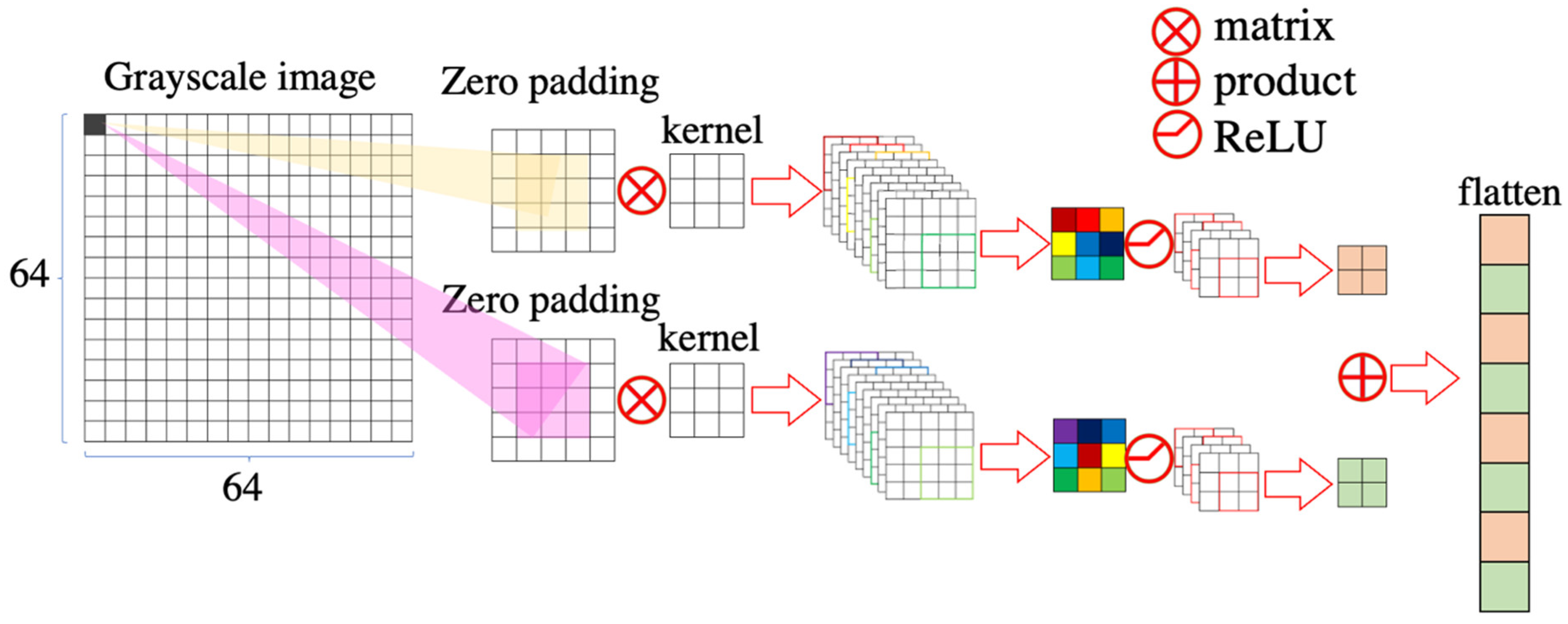
2.2.1. Design Chip of CNN

First of all, we completed the writing of the chip according to the general chip production process in Figure 2. The method written this time first wrote a basic convolution circuit chip and then made subsequent modifications based on this chip, applying the Winograd algorithm to it. In the basic convolution circuit chip architecture also shown in Figure 2, the CNN architecture was used as the calculation processing flow, and the order is Convolutional (Layer 0), Max-pooling (Layer 1), Flatten (Layer 2), a total of 3 layers [21,28], and this experiment adopted the input of the grayscale image [26,27].
First, at Layer 0, the input grayscale image (64 × 64 pixels in size) needed to be padded with zeros to maintain the final output result with the same size as the original image. This is to keep the CNN stackable into CNNs [29] and then use 2 filters as kernel because the maximum pooling needs to be done later, which used the size of the kernel as 3 × 3. Then, the result of Layer 0 will be presented by the calculation result of Rectified Linear Unit (ReLU) [30]. Then, the ReLU used here used a nonlinear-ReLU whose function is f ( x ) = max ( 0 , x ) , and this method output result of this ReLU will only store positive numbers, and negative numbers will become 0. While using a simple activation function for fast prediction, the CNN architecture failed to produce convincing results when using single-layer convolutions. CNNs are large one-layer architectures, while a single layer is not as good as expected, but the results after stacking are satisfactory [30,31]. The ReLU activation function was used to maintain the gradient at a positive value so that the result does not disappear [32]. Finally, the result of the Layer 0 is currently two matrices with a size of 64 × 64-pixel images.
Next, we used the result of Layer 0 as the input of Layer 1 and performed max pooling. The max pooling method can capture part of the position information and feature strength of the frequency domain neurons and improve the classification performance of the convolutional neural network in the frequency domain [33]. Here we used a 2 × 2 matrix to do the max pooling window with a stride of 1. The result of Layer 1 will be a 32 × 32 matrix of pixels from 2 images. After that, in the last Layer, the output of Layer 1 was flattened.
As mentioned earlier, flattening was done in the last Layer, and the output result is a one-dimensional state. As we mentioned earlier, to classify images, we needed a classifier, which is generated in the last Layer. Even though the results of flattening lack connectivity, it is simple and effective to filter out the actual and effective features to evaluate and distinguish [34,35].
In the information processing part, it can also be seen from Figure 2 that under the CNN architecture, there will be a total of 8 outputs (green line) and 5 inputs (red lines) in the circuit. The output is a system busy indication signal, a grayscale image address signal and operation, an output memory read enable signal, an operation result memory read address signal, an operation output memory write enable signal, an operation result memory output signal, an operation result memory write address signal, and enable signal. As for the input part, they are the system clock signal, the system reset signal, the grayscale image ready indication signal, the input grayscale image pixel data signal, and the operation result memory read signal—a total of five input signals.

2.2.2. Enhance Convolutional Calculated Speed

According to the Winograd method, we refer to the operation method using F ( 2 × 2 ,   3 × 3 ) [18,20]. For example, in Figure 3, we can see that a zero-filling 3 × 3 matrix in a 64 × 64 matrix with the grayscale picture will result in the same size as the original matrix after the kernel performs operations. From the beginning of zero-padding, convolutional, ReLU, and max-pooling to flatten, you can learn from the figure in detail. Then, according to the basic CNN of Figure 3, we applied the Winograd algorithm to the algorithm of this circuit. This calculation method can be used on the 64 × 64 matrix we designed and applied to the operation corresponding to the CNN stride of 1 in the above convolutional layer. Because this experiment is a 64 × 64 matrix corresponding to a 3 × 3 kernel, according to this F ( 2 × 2 ,   3 × 3 ) method, and because we needed to do the zero-padding first, the input will be 3 × 3 of a matrix. Therefore, the number of multiplications can be reduced from 3 × 3 × 2 × 2 = 36 to the number of 4 × 4 = 16 in the output, so the multiplication here will save as much as 2.25 times. According to theory, it can be known that the overall circuit operation will be accelerated [18].
Next, we will briefly introduce how Winograd is applied to the convolution of this architecture in the hardware circuit. Originally, in terms of internal memory, we used a 3 × 3 matrix to scan grayscale images and let the 3 × 3 input perform matrix calculations on the 3 × 3 kernels to generate the result of the circuit, but in Winograd, because F ( 2 × 2 ,   3 × 3 ) way to do the operation, so it needs to be expanded into a 4 × 4 matrix and a 3 × 3 kernel in terms of input:
input = [ i 00 i 01 i 02 i 03 i 10 i 20 i 30 i 11 i 21 i 31 i 12 i 22 i 32 i 13 i 23 i 33 ]   kernel = [ k 00 k 10 k 20 k 01 k 11 k 21 k 02 k 12 k 22 ]  
In the above matrix, after the operation, a 2 × 2 matrix will be obtained in our output. The result is as follows:
output = [ o 00 o 10 o 01 o 11 ]
After Winograd’s F ( 2 × 2 ,   3 × 3 ) method [18], it can be deduced into the following form:
[ i 00 i 01 i 02 i 10 i 01 i 10 i 11 i 02 i 11 i 12 i 03 i 12 i 13 i 11 i 20 i 21 i 11 i 12 i 20 i 21 i 12 i 21 i 22 i 13 i 22 i 23 i 21 i 30 i 31 i 22 i 31 i 32 i 22 i 23 i 32 i 33 ] [ k 00 k 01 k 02 k 10 k 11 k 12 k 20 k 21 k 22 ] = [ o 00 o 01 o 10 o 11 ]
According to the matrix operation in the above figure, we can see that it can be split into Winograd’s F ( 2 ,   3 ) [18] by partitioning the matrix:
[ I 00 I 01 I 02 I 10 I 11 I 12 ] [ K 0 K 1 K 2 ] = [ O 0 O 1 ]
It can be found that the output type here is also composed of the results of Winograd’s F ( 2 ,   3 ) [18], and finally, we will get a result type as:
[ O 0 O 1 ] = [ M 0 + M 1 + M 2 M 1 M 2 M 3 ]
Among this, the output results here can be represented by the following methods [18]:
M 0 = ( D 00 D 02 ) K 0                             M 1 = ( D 10 + D 20 ) K 0 + K 1 + K 2 2
M 2 = ( D 20 D 10 ) K 0 K 1 + K 2 2                             M 3 = ( D 10 D 30 ) K 2
According to the observation, it can be found that the output parameters required by Winograd’s F ( 2 ,   3 ) are 4 fixed parameters, which are observed by his architecture [18]. There will be 16 kinds of fixed parameters. These 16 kinds of parameters are what we need to calculate and apply to our circuit according to the kernel, and the method designed at the beginning only has 9 kinds of parameters, which is 3 × 3. The original structure of the kernel is calculated. This is also the biggest difference between the overall architecture and the beginning because the circuit uses a clock to trigger when it performs its operations. It may be said that four pixels can be calculated at the same time when a clock signal is high, while the original algorithm can only calculate one pixel per period, so theoretically, the speed of the two is 9 times different (the total number of multiplications is reduced by 2.25 times) × 1 clock execution executes 4 operations simultaneously times the difference. However, this inference is not rigorous enough.
First, the circuit was designed to be synchronous, and the pictures do not exist in the circuit, to begin with, because the circuit needs to calculate the results of different pictures. The above inference method assumes that the input is already fixed and exists in the memory. It can be said that the time to obtain the picture and the time to read the memory need to be deducted. However, as mentioned earlier, the circuit did not have a picture from the beginning. Moreover, it is an impractical method to make the picture pre-input circuit. Because of the limitation of memory and area, if a 64 × 64 matrix is imported and zero-padding is done, it will generate 64 × 64. If you use this matrix for operations, even if it is flattened into a 1-dimensional matrix, most of the memory in the circuit will be occupied. Because of hardware limitations, this circuit will generate a lot of mistakes.
Therefore, we did not use the above method to design this circuit. In the beginning, the design had only one 1 × 9 matrix state in memory. Since a 3 × 3 core was used for operation, this circuit had three 1 × 9 matrices to store output results and parameters. Therefore, zero padding is added during the operation. Due to the design of the circuit, the pixel of the picture was obtained at the high potential moment of each clock pulse because, during the period from this to the next high potential, we only got one pixel, and this circuit was at the next high potential. The operation was completed before the potential arrived. However, because there is no large amount of memory to store the output results of the pixels, the design of the testbench allowed the circuit to read the signal at the moment of low potential so that we could write the pixels calculated by Layer 0 into the memory of the testbench for reading.
In the circuit designed based on the Winograd algorithm, the results deduced by the Winograd method were observed [18], and one operation was a 4 × 4 matrix multiplied by a 3 × 3 matrix. However, according to the result, what we needed was to use the converted output parameters to calculate the result, so here we used a 4 × 4 matrix to store the input, and the converted parameters according to the kernel and the input were also stored in a 4 × 4 structure.
The above is the main difference in the circuit design of the two. The subsequent calculation method is because the results have been stored in the memory of the testbench, so the subsequent calculation methods are the same steps for both.

2.2.3. Authentication Method

To make our circuit more reliable, we used Synopsys’s TetraMax software for testing, input the test vector to signal Scan_out through Scan_in, and analyzed the error coverage rate of the circuit. The higher the error that can be detected, the higher the reliability of the chip. The TetraMAX ATPG test was to ensure that the original design rules were still met after adding the test circuit [36].

2.2.4. Automatic Layout and Routing

After adding the test circuit, the next step was automatic layout and routing. We needed to prepare the IO placement of the chip in advance, design the SDC of various timing constraints in the chip, and the Netlist after DFT. Here we used Cadence’s Innovus for automatic layout [37]. Winding, after the winding is completed, the GDS file for the subsequent DRC and LVS will be output, and the process of automatic layout and winding APR is roughly divided into IO placement, floorplan, power plan, placement, CTS, and routing. IO placement is our beginning. For the written IO placement, after placement, we needed to set the ratio that the chip needed to use and the distance to the pad. These settings affected the subsequent process, so it was very important. Here we used a ratio of 0.7; the higher the ratio, the larger the space used by the chip, but this would compress the space for the subsequent wiring, and the timing would be more compact. After the above floorplan was completed, a power plan was performed. This project is mainly to set the power supply to the chip, respectively, from the power ring to the power stripe and finally to the pad pin. Placement mainly carries out the placement of components. CTS (Clock Tree Synthesis) mainly allows our timing to reach each component in an average time. Buffer is used to achieve balance, and routing is to confirm that all the routings are correct. At this point, the automatic layout routing is over. The flow chart is shown in Figure 4, and the next step is the verification of DRC & LVS.
After the automatic layout and winding are completed, it is the verification of DRC and LVS. In this verification, it will be checked whether the winding part conforms to TSMC’s process regulations, such as wire-to-wire distance and metal area. When there was a violation, it was because there was a process error that prevented smooth offline, and LVS compares the GDS file generated after APR with the Schematic circuit diagram, mainly to verify whether the circuit is consistent, and NanoSim verification can be performed after the DRC and LVS are completed [38].
After passing the DRC and LVS verification, we needed to use Nanosim to replace the components in the original GDS with the real Layout file. On Nanosim, we used typical nMOS and typical pMOS (TT), fast nMOS and fast pMOS (FF), and slow nMOS and slow pMOS (SS), representing three different speeds to simulate the waveform of TT. The transition time is an ideal state, the waveform transition of FF will be earlier, and SS will be delayed, but the power consumption of FF is large, and the power consumption of SS is small. This is because when designing, designers often consider finding the best and worst case.

2.2.5. Model Selection

According to much literature, models with convolutions perform well in training and judging images, so it can be seen that most studies also use CNN-related models if they want to train models [39,40,41,42]. Therefore, this experiment uses Winograd’s method to accelerate the convolutional layer, but in this experiment, in addition to analyzing the specifications, we also performed model analysis. This time, we used chest X-ray images as input to train the CNN model in this experiment. This experiment used basic models to analyze architectures like the Bi-LSTM, CNN, GRU, and VGG16 [39,42,43,44]. Although the effect of the Bi-LSTM or GRU model in analyzing images may not be as obvious as that of traditional CNN or VGG16 because their architecture is also synthesized by convolution, considering that we are in testing the detection effect of convolution on images, this type of model is also included in this experiment [43]. The 4 models will display training results on 4 different types of chest radiographs. To improve the training effect of the model, the input of this image used the power of 2, that is, the input of 256 × 256   for touch training and the training data was stored in the memory, which has better memory usage during training. Since nearly 50% of the distribution of the data is normal lung, followed by lung opacity, COVID-19, and viral pneumonia, without data augmentation, training will be poor. Therefore, in the data collection, we used the data augmentation method to expand the data so that the training had a better effect.
The GPU we used was Tesla’s T4 or P100 graphics card for training, and we did not make too many adjustments to the parameters. All four models set the same parameters in the fine-tuning parameters, which refer to the general CNN architecture we built. In general, only the internal architecture of the model varied. The parameters varied slightly due to the different architectures, but in general, we did not make more subtle adjustments and only did 120 epochs per model. In terms of the learning rate, the model started from 0.02 and adjusted the learning rate gradient downward by detecting the loss on the validation set to get better training results [45].

3. Results

3.1. Specification

In the specification part of the chip implementation, shown in Table 1, we used the TSMC 1P6M 0.18 μm process to finish the circuit, as shown in Figure 5. In the results, we have successively compared the traditional CNN computing chip and Winograd accelerated computing under the same manufacturing, the biggest difference between traditional CNN and Winograd. This difference is the complexity of the circuit because Winograd needs to use a larger number of flip-flops to convert the value of the convolution circuit, which will also indirectly lead to an increase in Chip Size and Core Size. This can be seen from the Gate Count. It can be seen that the Gate Count of the two is also about 5.1 times different. It can also be seen that the area difference between the two is about 1.65 times. With the increase of Gate Count, the overall power consumption of the Winograd CNN architecture is increased by nearly 140 MW, nearly 2.9 times, compared to the increase of the Basic CNN architecture. The fault coverage here is not much different, and they all perform well because they are optimized with the help of EDA tools in this experiment. Finally, the thing to see is the convolution computation time for both. Our measured results are 2.937 ms under the Basic CNN architecture and 1.735 ms under the Winograd CNN architecture; this is close to 1.69 times.
In addition to the comparison of the two circuits, we also compared the circuit differences of Winograd in Specification, Pre-Sim, and Post-Sim in Table 1, and then whether the circuit synthesized by the synthesizer was as described in the original design, that is, considering the gate delay. After Pre- sim, the overall area is slightly increased compared to the Specification, but the Power Consumption is slightly reduced.
After the completion of the Place and Routing Post-sim, the overall Chip Size and Core Size are higher than the previous two. Therefore, the Power Consumption is also higher than the previous two. In the Gate Count part, after more optimizations, the Gate Count of Pre-sim is the smallest among the three, Post-sim is the second because of the routing increase, and Specification is the largest.

3.2. Waveform

The input of the circuit we designed is a grayscale image. As mentioned earlier, this circuit needs to complete the operation process of three layers, namely Convolutional, Max-pooling, and Flatten, as shown in Figure 2. As can be seen from Figure 6, this circuit is a positive edge trigger circuit, and the reset signal will be set at the beginning of this circuit to ensure that each signal will be reset to avoid the initial value of the circuit not being set at the beginning, resulting in subsequent abnormal results. After three clock signals, initialization is complete. When waiting for the convolution circuit to perform operations, that is, when the testbench sends a signal in, if the ready signal of the initial circuit is high, it means that the grayscale image data and the kernel data of each layer are ready.
After the initialization is completed, the convolution circuit will set its busy signal to a high potential. At this time, if the testbench detects that the busy signal is high, it will set the ready signal to a low potential, indicating that the testbench is waiting for convolution. The circuit handles the three layers of action required. In this circuit, busy main judges this circuit, and ready is the point for the testbench to judge. After waiting for the operation of each layer to be completed or for the action to be performed has been completed, the convolution circuit can set the busy signal low again. When all the operations of the circuit are completed, the testbench will prepare the next grayscale image and set the busy signal. It is a low potential, and the testbench will immediately enter to verify the data to ensure that the results are correct, and this result will be verified by Python processing before it can be used as the verification data of the convolution circuit.
Therefore, for the operation processing of each input grayscale image, the busy signal is only allowed to be set to a high potential when the convolution circuit starts to work and is set to a low potential when the convolution operation is completed. At the same time, in the process that busy is equal to the high potential, the convolution circuit can repeat the read and write operations of each Layer infinitely.

3.3. Curve of Model

So far, the above are the performance, computation time, and chip-related data of the Winograd CNN chip with 64 × 64 matrix input and the base CNN chip fabricated under 0.18 μm measured under the TSMC process. Next, in the following discussion, we will compare the training effect of the model we also did in this experiment, as shown in Figure 7, and we will analyze the effect of the model through some data. In this experiment, we also recorded the training time of each model in this experiment, which is 6 h, 5 h, 6 h, and 14 h by CNN, Bi-LSTM, GRU, and the VGG16, respectively. In terms of parameters, respectively, 2,368,964, 2,692,396, 2,012,396, and 166,045,508. It can be seen that although the number of meals of the three models is similar, the Bi-LSTM structure will have a faster training speed. Because of the structural relationship of VGG16, although the training time is relatively long, its training efficiency can be said to be the best.
We also set the number of training times to 120 times, and from Figure 8, we can see that the learning of our model starts from 0.02 and detects loss performance. If the loss did not drop for 10 consecutive epochs, we reduced our learning loss so that the model had better training results.

4. Discussion

4.1. Calculating Time

From the above results and experimental methods, it can be seen that in the circuit analysis of convolution, our computational time method can be analyzed. From the way it is designed, if the output of a convolutional layer is a 2 × 2 output, then using the Winograd algorithm, the number of reads will be reduced from 36 input reads to only 16 inputs. Considering the relationship of the period in this circuit, it is not because of reducing the number of multiplications to speed up the calculation of the circuit. The difference from the theoretical analysis speed is that in a circuit with the same frequency and where the input is limited by memory usage, the circuit will not be able to input the picture in advance and store all the pixels in the circuit. If the Winograd algorithm is used under this calculation, the calculation speed of the circuit will be accelerated, mainly due to the reduction in the number of inputs.
Overall, it can be observed that our computation time differs by a factor of about 1.7 from the original computation time. Although it was mentioned earlier that the speed calculation under Winograd can be 2.25 times worse because the circuit uses the same architecture for max-polling and flattening after the convolutional layer, our circuit time is only about 1.7 times faster.

4.2. Model Analysis

In terms of models, we found that the Sigmoid function would not be able to train without Batch Normalization when training these images. When this problem occurs, it can be observed that the training loss will not decrease and the prediction accuracy will not increase after multiple pieces of training, and the valid loss is the same, so we follow the records of the literature after the convolutional layer of each model. Both have added batch normalization to prevent gradient vanishing issues [46].
Moreover, it can be observed that although we have added the layer of LSTM or GRU basic on the CNN model, the parameters in the result are similar because we have the layer of convolutional in the trimming model alone. Therefore, according to Table 2, it can be seen that the accuracy rate becomes lower, especially after adding the layer of LSTM, and the accuracy rate becomes lower than other models.
It can also be seen that in this experiment, the general CNN model performs the best, but the effect of the long and short-term memory layer in the CNN model is not very good. Presumably, in the training of this grayscale image, a convolutional model was used. The effect will be better than long short-term memory. For VGG16 in this experiment, as mentioned earlier, we also added batch normalization to each layer. What is more interesting is that in the first 20 epochs, we can see that the loss of VGG16 will suddenly increase, but the model does not explode for this reason. Although the basic CNN also has this problem, compared with VGG16, this problem becomes less obvious, and the LSTM and GRU models do not have this problem.
In addition, in Figure 7, it can also be observed that loss and accuracy are related. If there is an epoch where the loss suddenly changes significantly, you can see that the effect of training at that time will lead to a significant decrease in accuracy. The reason for this is that we have issues that require special attention. At present, according to our speculation, it is because there are CNN and VGG16 in the epochs that are not trained according to the time record of LSTM or GRU, so this problem occurs because the training gradient of a certain Layer in training disappears, resulting in the result showing a difference.
Besides, we compared our proposed model on COVID-19 diagnosis tasks with those of previous SOTA COVID-19 screening methods, which included Shi [47], Wang [48], and Xu [47] in Table 3. Shi [47] presented an infection region-specific segmentation technique based on a random forest model to distinguish COVID-19 from other forms of pneumonia using CT exams [47]. This study reported 83.30% accuracy [47]. Wang [48] designed a COVID-Net framework tailored to identify COVID-19 from chest radiography [48] and achieved 82.9% accuracy. Xu [47] proposed an AI-based technique to screen coronavirus from healthy and viral pneumonia using CT exams and reported 86.7% accuracy [47]. Comparing these forward-looking methods, our proposed method has higher accuracy.

4.3. Limitations and Future Directions

Based on the above results, it can be found that the structure of the hardware circuit will directly affect the performance, area, and speed of the circuit. Although the outputs of the two circuits are the same, the operation methods of the circuits are also very different. For example, the Winograd acceleration circuit greatly reduces the number of multiplications in traditional CNN operations and replaces them with additions, which are much faster than multiplications in hardware implementation. Because the number of multiplications in Winograd is greatly reduced, an acceleration method is also proposed here, which is to change the maximum frequency of the circuit, such as directly increasing the maximum frequency from 100 MHz to 200 MHz, to test whether the circuit can accelerate the calculation. Due to the reduction in the number of multiplications, it is obvious that the cycle required for the circuit calculation can be relatively reduced.
The biggest sacrifice in the acceleration circuit is also the area. Because of the use of the conversion matrix, under the TSMC 0.18 μm process, the area occupied by the Winograd circuit is very large, but with the help of EDA tools, it has reduced the original substantial growth.
For the model part, because the chest X-rays and their information are not a public resource, although we tried to adjust the learning rate and expand the data, the amount of data also limited our training results. Although the types of data are very similar, after trying and comparing various models, a model with an accuracy rate of more than 85% was finally trained. If the X-ray information of the lungs becomes more transparent and public in the future, the increase in the amount of data is believed to be beneficial to us. The accuracy of the model is greatly improved, and it can also be trained with deeper and larger models.
For the chip part of the future outlook, it is hoped that the neural network model can be used as a hardware circuit to realize a circuit that can fully connect the layer from the input of the model to the output and realize the function of the classification. Because the overall architecture is larger, more often, it needs to be implemented in a better process to achieve small-area, high-speed, high-performance chips. Because of the physical chip, we also hope to operate the results through the actual human-machine interface in the future, and it is also expected that the accuracy rate can be adjusted to more than 95% for the reference of real medical teams. The promotion model is also the final result we hope to achieve, and we hope that the results we have achieved can serve as a cornerstone and contribute to the development of this severe epidemic.

5. Conclusions

Based on the above discussion and results, this article takes convolution in commonly used models as the research basis. For the convolution in the CNN operation, the Winograd calculation method is used, and this operation method is implemented in the circuit, and the difference is compared. It can be known that the difference in speed is not the difference in the expected multiplication, although the overall operation is different. The multiplication is reduced by about 2.25 times, but because of the limitation of the clock and the memory, the application in the circuit instead focuses on how the same input operates and how to reduce the calculation amount of the circuit. The above is what needs to be paid attention to in the actual circuit work.
In this article, we only changed the model of the neural network, and there are obvious differences, including accuracy, loss, etc. Therefore, although the data occupies a large factor in the results of the neural network, the architecture and selection of the model will also directly affect the overall results.
Although we all know that CNN is good at classifying pictures, the issue of multi-class classification of gray-scale pictures has not been highlighted. In order to solve this problem, we use the result of Layer 0 as the input of Layer 1 and perform max pooling that can capture part of the position information and feature strength of the frequency domain neurons and improve the classification performance of the convolutional neural network in the frequency domain in this paper. Besides, flattening is done in the last Layer, and the output result is a one-dimensional state. We design a classifier, which is generated in the last layer to classify images. The proposed method is simple and effective and filters out the actual and effective features to evaluate and distinguish. In this experiment, grayscale pictures are used as input, and chest X-rays are used to train CNN Related models, synthesize four related classifications, analyze the training effect of the CNN model, and related research for future development.

Author Contributions

Methodology, Y.-C.F.; Software, K.-Y.L. and Y.-H.T.; Data curation, K.-Y.L. and Y.-H.T.; Writing—review & editing, K.-Y.L.; Project administration, Y.-C.F. All authors have read and agreed to the published version of the manuscript.

Funding

This work was supported by the Ministry of Science and Technology of Taiwan under Grant MOST 110-2221-E-027-084-MY3.

Institutional Review Board Statement

Not applicable.

Informed Consent Statement

Not applicable.

Conflicts of Interest

The authors declare no conflict of interest.

References

  1. Male, V. SARS-CoV-2 infection and COVID-19 vaccination in pregnancy. Nat. Rev. Immunol. 2022, 22, 277–282. [Google Scholar] [CrossRef]
  2. Boni, M.F.; Lemey, P.; Jiang, X.; Lam, T.T.; Perry, B.W.; Castoe, T.A.; Rambaut, A.; Robertson, D.L. Evolutionary origins of the SARS-CoV-2 sarbecovirus lineage responsible for the COVID-19 pandemic. Nat. Microbiol. 2020, 5, 1408–1417. [Google Scholar] [CrossRef] [PubMed]
  3. Zhan, C.; Tse, C.K.; Gao, Y.; Hao, T. Comparative Study of COVID-19 Pandemic Progressions in 175 Regions in Australia, Canada, Italy, Japan, Spain, U.K. and USA Using a Novel Model That Considers Testing Capacity and Deficiency in Confirming Infected Cases. IEEE J. Biomed. Health Inform. 2021, 25, 2836–2847. [Google Scholar] [CrossRef]
  4. Regmi, S.; Malla, K.P.; Adhikari, R. Current scenario of COVID-19 pandemics in the top ten worst-affected countries based on total cases, recovery, and death cases. Appl. Sci. Technol. Ann. 2020, 1, 92–97. [Google Scholar] [CrossRef]
  5. Sitaula, C.; Basnet, A.; Mainali, A.; Shahi, T.B. Deep Learning-Based Methods for Sentiment Analysis on Nepali COVID-19-Related Tweets. Comput. Intell. Neurosci. 2021, 2021, 2158184. [Google Scholar] [CrossRef]
  6. Nishio, M.; Noguchi, S.; Matsuo, H.; Murakami, T. Automatic classification between COVID-19 pneumonia, non-COVID-19 pneumonia, and the healthy on chest X-ray image: Combination of data augmentation methods. Sci Rep. 2020, 10, 17532. [Google Scholar] [CrossRef]
  7. Williams, G.D.; Townsend, D.; Wylie, K.M.; Kim, P.J.; Amarasinghe, G.K.; Kutluay, S.B.; Boon, A.C.M. Nucleotide resolution mapping of influenza A virus nucleoprotein-RNA interactions reveals RNA features required for replication. Nat. Commun. 2018, 9, 465. [Google Scholar] [CrossRef] [Green Version]
  8. Qayyum, A.; Qadir, J.; Bilal, M.; Al-Fuqaha, A. Secure and robust machine learning for healthcare: A survey. IEEE Rev. Biomed. Eng. 2021, 14, 156–180. [Google Scholar] [CrossRef]
  9. Gabriella, I.; Kamarga, S.A.; Setiawan, A.W. Early Detection of Tuberculosis Using Chest X-Ray (CXR) with Computer-Aided Diagnosis. In Proceedings of the 2018 2nd International Conference on Biomedical Engineering, Shanghai, China, 6–8 July 2018; pp. 76–79. [Google Scholar]
  10. Sitaula, C.; Hossain, M.B. Attention-based VGG-16 model for COVID-19 chest X-ray image classification. Appl. Intell. 2020, 51, 2850–2863. [Google Scholar] [CrossRef]
  11. Kalaiselvi, S.M.P.; Tang, E.X.; Moser, H.O.; Breese, M.B.H.; Turaga, S.P.; Kasi, H.; Heussler, S.P. Wafer scale manufacturing of high precision micro-optical components through X-ray lithography yielding 1800 Gray Levels in a fingertip sized chip. Sci. Rep. 2022, 12, 2730. [Google Scholar] [CrossRef]
  12. Su, L.; Fu, X.; Zhang, X.; Cheng, X.; Ma, Y.; Gan, Y.; Hu, Q. Delineation of carpal bones from hand X-ray images through prior model, and integration of region-based and boundary-based segmentations. IEEE Access 2018, 6, 19993–20008. [Google Scholar] [CrossRef]
  13. Cho, H.; Kim, Y.; Lee, E.; Choi, D.; Lee, Y.; Rhee, W. Basic Enhancement Strategies When Using Bayesian Optimization for Hyperparameter Tuning of Deep Neural Networks. IEEE Access 2020, 8, 52588–52608. [Google Scholar] [CrossRef]
  14. Van Grinsven, M.J.; van Ginneken, B.; Hoyng, C.B.; Theelen, T.; Sánchez, C.I. Fast convolutional neural network training using selective data sampling: Application to hemorrhage detection in color fundus images. IEEE Trans. Med. Imaging 2016, 35, 1273–1284. [Google Scholar] [CrossRef] [PubMed]
  15. Mehrabian, A.; Miscuglio, M.; Alkabani, Y.; Sorger, V.J.; El-Ghazawi, T. A Winograd-Based Integrated Photonics Accelerator for Convolutional Neural Networks. IEEE J. Sel. Top. Quantum Electron. 2019, 26, 1–12. [Google Scholar] [CrossRef] [Green Version]
  16. Wang, X.; Wang, C.; Cao, J.; Gong, L.; Zhou, X. WinoNN: Optimizing FPGA-Based Convolutional Neural Network Accelerators Using Sparse Winograd Algorithm. IEEE Trans. Comput. Des. Integr. Circuits Syst. 2020, 39, 4290–4302. [Google Scholar] [CrossRef]
  17. Hu, X.; Xu, X.; Xiao, Y.; Chen, H.; He, S.; Qin, J.; Heng, P.-A. SINet: A Scale-Insensitive Convolutional Neural Network for Fast Vehicle Detection. IEEE Trans. Intell. Transp. Syst. 2018, 20, 1010–1019. [Google Scholar] [CrossRef] [Green Version]
  18. Lavin, A.; Gray, S. Fast Algorithms for Convolutional Neural Networks. arXiv 2015, arXiv:1509.09308. [Google Scholar]
  19. Yepez, J.; Ko, S.B. Stride 2 1-D, 2-D, and 3-D winograd for convolutional neural networks. IEEE Trans. Very Large Scale Integr. Syst. 2020, 2, 853–863. [Google Scholar] [CrossRef]
  20. Fan, Y.-C.; Yelamandala, C.M.; Chen, T.-W.; Huang, C.-J. Real-Time Object Detection for LiDAR Based on LS-R-YOLOv4 Neural Network. J. Sensors 2021, 2021, 5576262. [Google Scholar] [CrossRef]
  21. Lin, K.Y.; Tsai, Y.H.; Fan, Y.C. A Model-Based Convolutional Neural Network for Covid-19 and Related Lung Diseases Prediction with Graphical Interface Operation and Chip Design. In Proceedings of the 2021 IEEE International Conference on Consumer Electronics-Asia (ICCE-Asia), Toseong-myeon, Republic of Korea, 1–3 November 2021; pp. 1–4. [Google Scholar]
  22. Bashir, I.; Staszewski, R.B.; Eliezer, O.; de-Obaldia, E. Built-in Self Testing (BIST) of RF Performance in a System-on-Chip (SoC). In Proceedings of the 2005 IEEE Dallas/CAS Workshop on Architecture, Circuits and Implementtation of SOCs, Richardson, TX, USA, 10 October 2005; pp. 215–218. [Google Scholar]
  23. Fan, Y.-C. Testing-Based Watermarking Techniques for Intellectual-Property Identification in SOC Design. IEEE Trans. Instrum. Meas. 2008, 57, 467–479. [Google Scholar]
  24. Fan, Y.C.; Tsao, H.W. Boundary scan test scheme for IP core identification via watermarking. IEICE Trans. Inf. Syst. 2005, 88, 1397–1400. [Google Scholar] [CrossRef]
  25. Fan, Y.C.; Shen, J.H. DFT-based SoC/VLSI IP protection and digital rights management platform. IEEE Trans. Instrum. Meas. 2008, 58, 2026–2033. [Google Scholar]
  26. Chowdhury, M.E.; Rahman, T.; Khandakar, A.; Mazhar, R.; Kadir, M.A.; Mahbub, Z.B.; Islam, K.R.; Khan, M.S.; Iqbal, A.; Al Emadi, N.; et al. Can AI help in screening viral and COVID-19 pneumonia? IEEE Access 2020, 8, 132665–132676. [Google Scholar] [CrossRef]
  27. Rahman, T.; Khandakar, A.; Qiblawey, Y.; Tahir, A.; Kiranyaz, S.; Kashem, S.B.A.; Islam, M.T.; Al Maadeed, S.; Zughaier, S.M.; Khan, M.S.; et al. Exploring the effect of image enhancement techniques on COVID-19 detection using chest X-ray images. Comput. Biol. Med. 2021, 132, 104319. [Google Scholar] [CrossRef] [PubMed]
  28. Lecun, Y.; Bottou, L.; Bengio, Y.; Haffner, P. Gradient-based learning applied to document recognition. Proc. IEEE 1998, 86, 2278–2324. [Google Scholar] [CrossRef] [Green Version]
  29. Liu, M.; He, Y.; Jiao, H. Efficient Zero-Activation-Skipping for On-Chip Low-Energy CNN Acceleration. In Proceedings of the 2021 IEEE 3rd International Conference on Artificial Intelligence Circuits and Systems (AICAS), Washington, DC, USA, 6–9 June 2021; pp. 1–4. [Google Scholar]
  30. Uchida, K.; Tanaka, M.; Okutomi, M. Coupled Convolution Layer for Convolutional Neural Network. In Proceedings of the 2016 23rd International Conference on Pattern Recognition (ICPR), Cancun, Mexico, 4–8 December 2016; pp. 3548–3553. [Google Scholar]
  31. Fan, Y.C.; Wu, B.T.; Huang, C.J.; Bai, Y.H. Environment Detection of 3D LiDAR by Using Neural Networks. In Proceedings of the 2019 IEEE International Conference on Consumer Electronics, IEEE ICCE 2019, Las Vegas, NV, USA, 11–13 January 2019; pp. 1–2. [Google Scholar]
  32. Cai, K.; Chen, H.; Ai, W.; Miao, X.; Lin, Q.; Feng, Q. Improvement of learning for CNN with ReLU activation by sparse regularization. In Proceedings of the 2017 International Joint Conference on Neural Networks (IJCNN), Anchorage, AK, USA, 14–19 May 2017; pp. 2684–2691. [Google Scholar]
  33. Lin, J.; Ma, L.; Cui, J. A frequency-domain convolutional neural network architecture based on the frequency-domain randomized offset rectified linear unit and frequency-domain chunk max pooling method. IEEE Access 2020, 8, 98126–98155. [Google Scholar] [CrossRef]
  34. Jin, J.; Dundar, A.; Culurciello, E. Flattened Convolutional Neural Networks for Feedforward Acceleration. arXiv 2015, arXiv:1412.5474. [Google Scholar]
  35. Sultana, S.; Iqbal, M.Z.; Selim, M.R.; Rashid, M.; Rahman, M.S. Bangla Speech Emotion Recognition and Cross-Lingual Study Using Deep CNN and BLSTM Networks. IEEE Access 2021, 10, 564–578. [Google Scholar] [CrossRef]
  36. Multicore and Distributed Processing with TetraMAX ATPG. Available online: https://www.synopsys.com/content/dam/synopsys/implementation&signoff/white-papers/TMAX_Multicore_WP.pdf (accessed on 13 December 2022).
  37. Innovus Implementation System | Cadence. Available online: https://www.cadence.com/en_US/home/tools/digital-design-and-signoff/soc-implementation-and-floorplanning/innovus-implementation-system.html (accessed on 13 December 2022).
  38. NanoSim® User Guide. Available online: https://picture.iczhiku.com/resource/eetop/ShkGZkQIGqFWtCvn.pdf (accessed on 13 December 2022).
  39. Hattikatti, P. Bangla Speech Emotion Recognition and Cross-Lingual Study Using Deep CNN and BLSTM Networks. In Proceedings of the 2017 International Conference on Big Data, IoT and Data Science (BID), Pune, India, 20–22 December 2017; pp. 20–22. [Google Scholar]
  40. Da Nóbrega, R.V.M.; Peixoto, S.A.; da Silva, S.P.P.; Rebouças Filho, P.P. Lung Nodule Classification via Deep Transfer Learning in CT Lung Images. In Proceedings of the 2018 IEEE 31st International Symposium on Computer-Based Medical Systems (CBMS), Karlstad, Sweden, 18–21 June 2018; pp. 244–249. [Google Scholar]
  41. Singh, K.K.; Singh, A. Diagnosis of COVID-19 from chest X-ray images using wavelets-based depthwise convolution network. Big Data Min. Anal. 2021, 4, 84–93. [Google Scholar] [CrossRef]
  42. Panthakkan, A.; Anzar, S.M.; Al Mansoori, S.; Al Ahmad, H. Accurate prediction of covid-19 (+) using ai deep vgg16 model. In Proceedings of the 2020 3rd International Conference on Signal Processing and Information Security (ICSPIS), Virtual, 25–26 November 2020; Volume 4, pp. 1–4. [Google Scholar]
  43. Li, C.; Zhan, G.; Li, Z. News Text Classification Based on Improved Bi-LSTM-CNN. In Proceedings of the 2018 9th International Conference on Information Technology in Medicine and Education (ITME), Hangzhou, China, 19–21 October 2018; pp. 890–893. [Google Scholar]
  44. Yang, S.; Yu, X.; Zhou, Y. LSTM and GRU Neural Network Performance Comparison Study: Taking Yelp Review Dataset as an Example. In Proceedings of the 2020 International Workshop on Electronic Communication and Artificial Intelligence (IWECAI), Shanghai, China, 1–4 June 2020; pp. 98–101. [Google Scholar]
  45. Smith, L.N. Cyclical Learning Rates for Training Neural Networks. arXiv 2017, arXiv:1506.01186. [Google Scholar]
  46. Ioffe, S.; Szegedy, C. Batch Normalization: Accelerating Deep Network Training by Reducing Internal Covariate Shift. arXiv 2015, arXiv:1502.03167. [Google Scholar]
  47. Shi, F.; Xia, L.; Shan, F.; Song, B.; Wu, D.; Wei, Y.; Yuan, H.; Jiang, H.; He, Y.; Gao, Y.; et al. Large-scale screening to distinguish between COVID-19 and community-acquired pneumonia using infection size-aware classification. Phys. Med. Biol. 2021, 66, 65031. [Google Scholar] [CrossRef] [PubMed]
  48. Wang, L.; Lin, Z.Q.; Wong, A. Covid-net: A tailored deep convolutional neural network design for detection of COVID-19 cases from chest X-ray images. Sci. Rep. 2020, 10, 19549. [Google Scholar] [CrossRef] [PubMed]
Figure 1. Basic CNN and Winograd CNN ICs design flow from RTL to Tape Out.
Applsci 12 12891 g001
Figure 2. Image convolution test bench with 20 signal circuits and 5 memories with CNN architecture diagram with 3 layers, and the architecture of the proposed stride 1 CNN for classification. The kernel of the architecture was set to 3 × 3, the input set to 64 × 64, and the output set to 4096 × 1.
Applsci 12 12891 g002
Figure 3. Analytical diagram of the actual convolution operation performed on the 3 × 3 kernel.
Applsci 12 12891 g003
Figure 4. The proposed entity makes a flow chart of the architecture of the verification mechanism.
Applsci 12 12891 g004
Figure 5. By TSMC 0.18 μm process, the physical circuit was produced with 144 pins.
Applsci 12 12891 g005
Figure 6. The real signal indicates that “CLK” represents the signal of the clock, and “circuit” represents the action of the computing circuit, and the other things that are not mentioned are related to the above-mentioned signals. The red dotted line represents the alignment of the signals.
Applsci 12 12891 g006
Figure 7. The curve of the training results for the chest X-ray film per model in (a) accuracy of the training data, (b) accuracy of the validation data, (c) total loss of training data, and (d) total loss of validation data.
Applsci 12 12891 g007
Figure 8. The curve of the learning rate per model.
Applsci 12 12891 g008
Table 1. Chip basic specifications technical.
Item Basic CNNWinograd CNNWinograd Pre-SimWinograd Post-Sim
TechnologyTSMC 1P6M 0.18 μmTSMC 1P6M 0.18 μmTSMC 1P6M 0.18 μmTSMC 1P6M 0.18 μm
Chip Size 1.43   mm × 1.43   mm 1.86   mm × 1.86   mm 1.91   mm × 1.91   mm 1.91   mm × 1.91   mm
Core Size 0.82   mm × 0.82   mm 1.21   mm × 1.21   mm 1.3   mm × 1.3   mm 1.3   mm × 1.3   mm
PackageCQFP144CQFP144CQFP144CQFP144
Gate Count17,50290,23683,78784,426
Max Frequency100 MHz100 MHz100 MHz100 MHz
Fault Coverage99.54%99.90%99.90%99.90%
Power Supply1.62 V1.62 V1.62 V1.62 V
Power Consumption72.48 mW@100 MHz211.12 mW@100 MHz170.9 mW@100 MHz221.8 mW@100 MHz
Calculating Time2.937 ms1.734 msNoneNone
Table 2. Results indicators.
ModelAccuracyPrecisionRecallF-Score
Proposed87.87%88.48%86.67%87.37%
Bi-LSTM81.83%80.52%79.08%79.57%
GRU82.84%80.99%82.39%81.55%
VGG1685.49%84.56%84.21%84.17%
Table 3. Comparison of the proposed model with other state-of-the-art methods.
ModelShi [47]Wang [48]Xu [47]Proposed
Accuracy83.30%82.9086.787.87%
Publisher’s Note: MDPI stays neutral with regard to jurisdictional claims in published maps and institutional affiliations.

