Article

XtoE: A Novel Constructive and Camouflaged Adaptive Data Hiding and Image Encryption Scheme for High Dynamic Range Images

Department of Computer Science and Engineering, National Chung Hsing University, Taichung 402, Taiwan
*
Author to whom correspondence should be addressed.
Appl. Sci. 2022, 12(24), 12856; https://doi.org/10.3390/app122412856
Submission received: 4 November 2022 / Revised: 9 December 2022 / Accepted: 12 December 2022 / Published: 14 December 2022

Abstract

:
High dynamic range (HDR) image data hiding and encryption has attracted much interest in recent years due the benefits of providing high quality realistic images and versatile applications, such as copyright protection, data integrity, and covert communication. In this paper, we propose a novel constructive and camouflaged adaptive data hiding and image encryption scheme for HDR images. Our algorithm disguises hidden messages when converting an original OpenEXR format to the RGBE encoding, which contains the Red, Green, and Blue color channels and an exponent E channel. During the conversion process, we determine an optimal base for each pixel by considering the user’s demands and the exponent E channel information to achieve adaptive message concealment. To prevent inappropriate access to the stego image, we perform the bit-level permutation and confusion using a 2D Sine Logistic modulation map with hyperchaotic behavior and a random permutation scheme with the time complexity of O N . To the best of our knowledge, our algorithm is the first in HDR data hiding literature able to predict the image distortion and satisfy a user’s request for the embedding capacity. Our algorithm offers 18% to 32% larger embedding rate than that provided by the current state-of-the-art works without degrading the quality of the stego image. Experimental results confirm that our scheme provides high security superior to the competitors.

1. Introduction

High dynamic range (HDR) images [1,2] have attracted much interest in recent years because they offer a more dynamic range, allowing displays to show images in a clearer way, especially in the details of the highlights and shadows. Highlights can be shown brighter and truly dark, and deep shadows can be displayed. Thus, the original image can be shown more completely and faithfully, closer to what the human eye can see and perceive. Dynamic range is the ratio between the brightest and darkest values that a display can show. Using the floating-point number to store crucial information, HDR images can faithfully represent a large range of luminance and colors, thereby offering great potential to become the leading image standard.
There are three main HDR image encoding formats: RGBE [3], LogLuv [4], and OpenEXR [5]. Any two formats can be converted in either a forward or backward manner. Tone-mapping [1,2,6], an essential step for HDR images, consists of adjusting the tonal values of an image with a high dynamic range so that it can be viewed on digital displays. Tone-mapping operator, TMO, scales down the dynamic range while attempting to preserve the appearance of the original image. It is thus applied to HDR images to reveal their full details and give them a dynamic twist and realistic look, providing the best image presentation for visualizing an HDR image.
Data hiding [7], also known as steganography, is a technique developed to embed secret messages into digital media. The camouflaged media looks like the original harmless one, thus arousing no suspicion among malicious eavesdroppers. The media before message embedding is called a cover, and the media after the message concealment is referred to as a stego. In the era of internet transmission and cloud computing, data hiding provides a method for communicating secretly. While time-varying media, such as video, can be used as a carrier [8], static images are the most popular because they are widely transmitted over the Internet. Data hiding schemes using conventional low dynamic range (LDR) images, such as binary, grayscale, color, or palette images, have been presented in the extant literature [7,9,10].
Despite HDR images having the potential to become a leading standard, limited numbers of HDR data hiding works have been proposed in the literature. Similar to LDR image data hiding, the number of bits that an HDR image can carry is called the embedding capacity (EC). Taking the image resolutions into consideration, the embedding rate (ER) represents the number of bits concealed in a pixel, also denoted as bits per pixel (bpp). One of the goals pursued by a data hiding algorithm is providing an embedding rate that is large enough for practical applications. Cheng and Wang [11] proposed an adaptive data hiding and authentication algorithm for HDR RGBE images. They provided an embedding rate in the range of 5.13 to 9.69 bpp. The peak signal-to-noise ratios (PSNR) of the tone-mapped stego images are only slightly greater than the 30 dB. Li et al. [12] adopted HDR images with a 48-bit TIFF format and improved the embedding rate of Cheng and Wang’s scheme. Their algorithm offered an average embedding rate of 26 bpp, with the PSNR of the tone-mapped stego images between 30.47 and 37.00 dB. Chang et al. [13], Wang et al. [14], and Yu et al. [15] took advantage of modifying a homogeneity index to achieve distortion-free data hiding in HDR RGBE images. However, the penalty of this approach limited the embedding rate to only 0.127–0.145 bpp. Lin et al. [16] presented a novel data hiding algorithm (DHOB) and an aggressive bit encoding and decomposition (ABED) scheme for OpenEXR images. Depending on the parameters, the embedding rate was between 2.433 and 20.002 bpp. He et al. [17] and Gao et al. [18] employed prediction error expansion to embed a secret message in every individual Red, Green, and Blue color channel. Their algorithms provided embedding rates ranging from 1.202 to 2.85 bpp. Tsai et al. [19] applied the multiple-base notational system and homogeneity index modification and proposed an authentication algorithm for RGBE images. With the aid of the distortion tolerance, the embedding rate reached 2.27 bpp. Finally, Tsai et al. [20] extended the multi-MSB prediction and Huffman coding developed for LDR image and proposed reversible data hiding in encrypted RGBE images. Their scheme offered an embedding rate of 6.19–7.03 bpp.
Adaptive message embedding is an effective way for hiding data in LDR or HDR images. Since an HDR image can represent a large range of luminance and human eyes are not sensitive to the dark luminance, the darker pixels are better candidates than the brighter ones to carry more messages. Cheng and Wang’s algorithm [11] classified pixels of RGBE images into flat or boundary areas to embed different quantities of secret messages. Yu et al. [15] used the homogeneous representations inherent in the RGBE pixels to conceal different numbers of messages. Gao et al. [18] employed a two-level pixel prediction mechanism in complex regions of an RGBE image to reduce the distortion caused by message embedding. Targeting the OpenEXR images, Lin et al. [16] divided pixels into three categories based on the luminance and embedded more messages in low luminance pixels.
In the above works, secret messages were embedded by modifying pixels in a cover HDR image in order to generate a stego pixel, where the cover image and the stego image share the same image format. Data hiding using pixel modification inevitably produces interference with the natural features of a cover image, even though the modification is minor and even subtle. Consequently, the more that the information is concealed, the greater the image reveals distortion, which makes it difficult for these classical data hiding schemes to resist the attack of steganalysis, which intends to detect any secret messages hidden in an innocuous image. To resolve the potential steganalytic risk, a new data hiding scheme has been designed, which conceals secret messages by directly constructing a stego image rather than modifying the existing covers. This approach is termed “constructive data hiding” or “constructive steganography”. Technical algorithms developed to construct a stego image include texture synthesis [21] and color transfer [22], among others.
Image encryption [23,24] is an effective way for preserving privacy and maintaining security. While a number of low dynamic range (LDR) image encryption schemes have been presented [25,26], and unfortunately, research works on HDR encryption are limited. Yan et al. [27] used the elementary cellular automata (ECA) as an encryption tool to cipher RGBE images. Lin et al. [28] used a logistic map to generate a pseudo-random number sequence in order to encrypt an HDR image with the LogLuv format. Chen and Chang [29] encrypted the bits in the exponent field in OpenEXR images and obtain good encryption performance. Chen and Yan [30] proposed an encryption and authentication scheme for OpenEXR images; they made use of the torus automorphism as the permutation function and Vernam cipher as the stream cipher, where the plaintext is combined with a pseudo-random stream of data to generate the ciphertext using the Boolean “exclusive or” (XOR) function. Finally, Tsai et al. [20] reserved room for data hiding in the RGBE image, and then encrypted the image using a series of random binary digits. Their scheme is one of few algorithms in the extant literature that can conceal a secret message and encrypt an HDR image.
Security is perhaps the most important issue for image encryption [31,32]. However, the current state-of-the-art HDR encryption algorithms fail to analyze the security comprehensively. Some algorithms only present visual perception metric without further analysis, for example, Lin et al. [28] and Tsai et al. [20]. Apart from visual perception metric, some reported extra metrics including histograms and pixel correlation/key security results; for example, Yan et al. [27], Chen and Change [29], and Chen and Yan [30], which represent the most comprehensive work for security analysis. To the best of our knowledge, entropy analysis and image sensitivity analysis have never been presented by these HDR encryption algorithms in the extant literature. Without thorough security analysis, it remains unclear whether the image cipher actually does have a high security level able to resist malicious attacks, such as entropy attacks and differential attack [23,24].
This paper proposes a novel constructive data hiding and chaotic sequence-based bit-level image encryption algorithm. Our scheme offers six significant features. First, we conceal secret messages when converting an HDR image from the OpenEXR format into the RGBE one. From the steganalysis point of view, our scheme is able to resist the steganalytic attack because we construct a stego image rather than generate it from the existing cover image. Second, we adaptively embed a secret message according to the distribution of the exponent channel shared by the Red, Green, and Blue channels. The adaptivity enables our scheme to conceal more secret messages in pixels with low luminance, where their exponent value is smaller than the median of the whole HDR image. Third, we exploit adaptive message embedding to satisfy a user’s request. A user can request a large embedding rate in exchange for endurable image quality. Alternatively, an end user can exchange a limited embedding rate for a high quality stego image. Fourth, we introduce a chaotic sequence-based bit-level image encryption algorithm which not only protects the image contents, but also secures the hidden messages, thereby reducing the probability of any inappropriate use of the stego HDR RGBE image produced. We adopt a 2D Sine Logistic modulation map (2D-SLMM) [33] to generate pseudo-random sequences. The map holds two large positive Lyapunov exponent (LE) values and two large Kolmogorov entropy values, thereby providing better hyperchaotic behavior, more complexity, and unpredictability. Fifth, we apply the random permutation technique to our scheme in a bit-level permutation mechanism. As evidence from the experimental results, the bit-level permutation significantly increases the security of HDR image encryption. The final feature of our scheme is that we present six metrics to thoroughly and comprehensively evaluate the security of the cipher image.
The main contributions of our work can be summarized as follows:
  • We present a novel adaptive data hiding algorithm for an HDR image. Secret messages are concealed during the HDR format conversion, signifying that the cover and stego image are in different image formats, avoiding the vulnerability caused by conventional data hiding utilizing the cover image modification approach.
  • Our algorithm adaptively embeds secret messages. More secret messages are conveyed in those pixels containing low luminance appearing to be dark pixels, while fewer secret messages are injected into pixels with high luminance which appear to be brighter; this coincides with the phenomena that human eyes are less sensitive to the dark pixels and more sensitive to noticing subtle changes encountered in the brighter area.
  • Our data hiding scheme provides the ability to satisfy the request for the embedding rate proposed by the end user. In addition, image distortion due to the message concealment can be predicted prior to real message embedding. Thanks to the optimal base mechanism we introduce, which not only satisfies users’ demand, but also derives the minimal mean squared error to reduce the image distortion as small as possible. To the best of our knowledge, no algorithm in the HDR data hiding literature can comply with the embedding rate requested by the end user. In addition, there is no algorithm in the HDR imaging literature which can predict the distortion in terms of the mean squared error caused by the message concealment.
  • We present a secure image encryption scheme, which adopts a 2D-SLMM to generate a pseudo-random sequence with better hyperchaotic behavior. Pixels are ciphered through the bit-level permutation using the random permutation algorithm with the time complexity of O N . As a result, our scheme can completely shuffle the whole bits aligned by the Red, Green, Blue and Exponent channel in an HDR image.
  • We present a thorough and comprehensive security analysis for stego HDR RGBE images. Our scheme offers 18% to 32% more embedding rate than that provided by the current state-of-the-art works without impairing the quality of stego image. In addition, our scheme provides high image encryption security, surpassing those of our competitors. To the best of our knowledge, our scheme is the first that can report the security of HDR cipher image from six aspects: visual perception, histogram, correlation, entropy, image sensitivity, and key security.
The rest of this paper is organized as follows: Section 2 presents our proposed methods in detail. The experiments and analysis are given in Section 3. Finally, Section 4 describes conclusions and future work.

2. Our Proposed Methods

This section details our proposed algorithm for adaptive data hiding and image encryption for HDR images. Figure 1 exhibits the flowchart of our algorithm. In the sender part, two main processes are concurrent image conversion and adaptive message embedding (CICAME) and image encryption, while in the recipient part, there are image decryption and message extraction processes. Here, we briefly highlight these processes and will detail them in the following subsections.
To embed a secret message, the sender inputs the demanded target embedding rate ( E R t a r ), secret message {S}, and a source HDR OpenEXR image ( I E X R ). The first part of message embedding is converting I E X R into a new HDR image encoded by the RGBE format. During the conversion, we seamlessly embed secret message {S} into each pixel to generate the stego image ( I S ). Next, we encrypt I S using the encryption key ( k e ) to protect the image contents and secret hidden message. The resultant stego encrypted image ( I S E ) is then delivered to the recipient through a public channel, such as the Internet. In this way, the secret message is camouflaged during the format conversion and image encryption.
Image decryption and message extraction are conducted on the recipient side. The receiver first inputs the stego encrypted HDR RGBE image ( I S E ). It is then deciphered by the aid of the decryption key ( k d ) provided prior by the sender. The image decryption produces the stego HDR RGBE image ( I S ) which contains a hidden message. Finally, a secret message {S} is extracted from I S using the extraction key ( k x ), thereby completing the message extraction process. The following subsections detail each step in the message embedding and extraction processes.

2.1. Concurrent Image Conversion and Adaptive Message Embedding

In this process, we convert the input HDR image, I E X R , encoded by the OpenEXR format into the HDR image encoded by the RGBE format. 
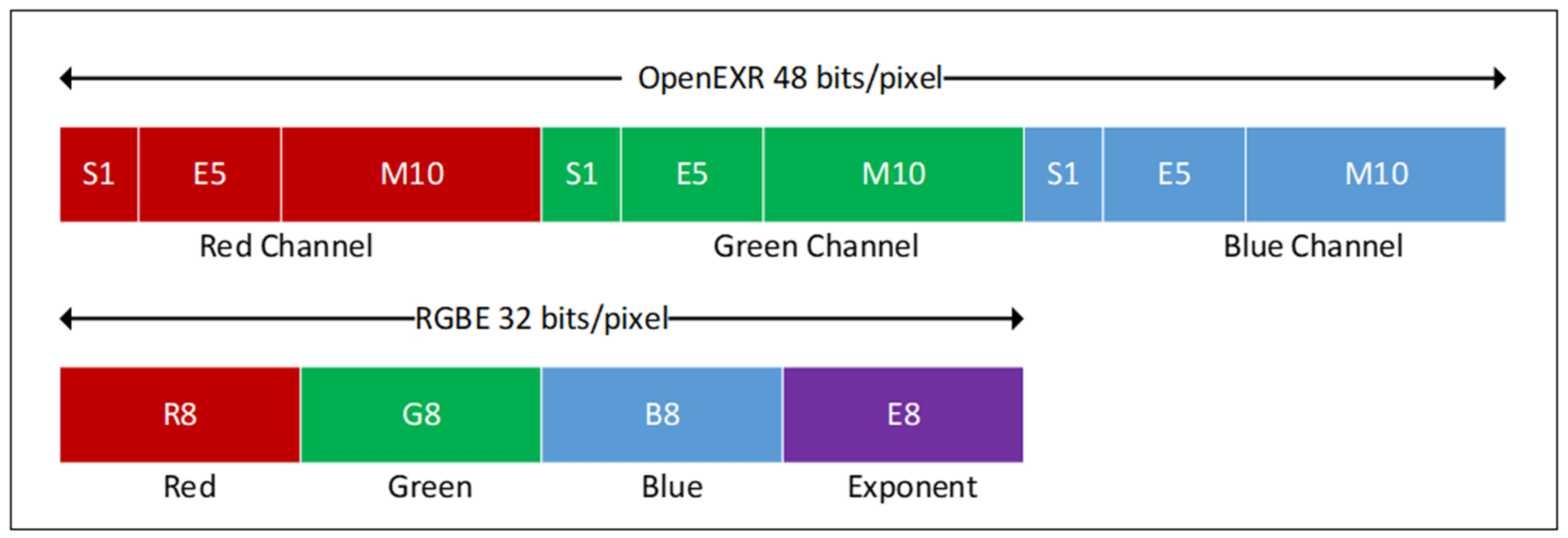
Figure 2 shows the 48-bit/pixel OpenEXR and 32-bit/pixel RGBE formats. A pixel in an OpenEXR image is represented by a floating-point vector, X = X R ,   X G ,   X B . The floating-point value in the corresponding Red, Green, and Blue channels can be converted from 1-bit sign, 5-bit exponent, and 10-bit mantissa fields. In contrast, a pixel in an RGBE image is denoted by P = P R ,   P G ,   P B ,   P E , representing the respective Red, Green, Blue, and the Exponent channels with 8-bit storage. During the conversion, we concurrently and adaptively embed a secret message, thus constructing a new stego HDR RGBE image, I S . The process is completed by the following five steps:
  • Step 1: Image conversion. An I E X R is converted into the HDR image encoded by the RGBE format. The expressions shown on the left expression in Equation (1) convert chromatic information into the four components in the RGBE format:
    P E = l o g 2 max X R ,   X G ,   X B + 128 ,     X R = P R + 0.5 256 × 2 P E 128 P R = 256 × X R 2 P E 128 , X G = P G + 0.5 256 × 2 P E 128 , P G = 256 × X G 2 P E 128 , X B = P B + 0.5 256 × 2 P E 128 , P B = 256 × X B 2 P E 128 ,
    where X = X R ,   X G ,   X B represents the i-th pixel in scene-referred color in I E X R and P = P R ,   P G ,   P B ,   P E denotes the i-th pixel in the corresponding RGBE HDR image. Note that we omit the index i if the expression does not cause any ambiguity. In a special case when max X R ,   X G ,   X B is less than 10 38 , the conversion is written out as 0 ,   0 ,   0 ,   0 . We can translate the integer representation in P = P R ,   P G ,   P B ,   P E back to the scene-referred color, X = X R ,   X G ,   X B , using the right expressions in Equation (1), which is also known as reverse conversion. In a special case described above, we directly translate to 0 ,   0 ,   0 .
Note that the four components, P R ,   P G ,   P B ,   P E , are integers within the range of [0, 255]. While the first three components, P R ,   P G ,   P B , represent the respective pixel values in the Red, Green, and Blue channels, the fourth component, P E , indicates the pixel value in the Exponent channel (hereafter E-channel).
  • Step 2: Optimal base determination. In this step, we determine an optimal base, B = b R ,   b G ,   b B , for the i-th pixel P , according to P E , i.e., this pixel’s value in the E-channel. An optimal base is required so that we can embed a secret message in the P R ,   P G ,   P B . In this paper, we convey a secret message in the Red-, Green-, and Blue-channels and leave the E-channel intact because the E-channel is the exponent shared by the other three channels, so any changes in it, for example, plus or minus n values ± n , will result in the magnitude of exponential changes, R ,   G ,   B × 2 ± n in three other components. Instead, we utilize the value of the E-channel in a pixel P as a guide to determine its corresponding optimal base, thereby achieving adaptive message embedding. We detail this step as follows.
Let P E   0 P E 255 represent the value of the pixel P in E-channel which is currently processed. Let E m denote the median of the pixels in the E-channel derived from the HDR RGBE image which has just been converted from an OpenEXR HDR image. Let F represent the minimal notational number system where an F-ary secret message can be concealed in P R ,   P G ,   P B . Inspired by the fact that human eyes are less sensitive to the pixel with low luminance (dark pixels), we derive F in Equation (2) as a function of P E because the constant, E R t a r , is given by the end user and the constant, E m , is derived from the HDR RGBE image,
F = 2 E R t a r × 2 E m P E .
The derived F strongly relates to the difference between P E and the median E m . If P E = E m , F = 2 E R t a r . This means that, if a pixel’s P E is identical to the median, the derived F equals the two’s power of the target embedding rate 2 E R t a r , as expected. However, if P E > E m , the derived F will be smaller than 2 E R t a r , and the larger the P E , the larger the difference between F and 2 E R t a r ; this means that fewer secret messages are conveyed in this pixel. In contrast, if P E < E m , the derived F will be larger than 2 E R t a r , and the smaller the P E , the larger the difference between F and 2 E R t a r , implying that more secret messages will be conveyed in this pixel. This approach coincides with the concept that since human eyes are less sensitive to the pixel with low luminance (dark pixels), more secret message can be concealed in a pixel with smaller P E (larger difference between E m and P E ) without causing noticeable difference. In this paper, we set E R t a r = 7.3 bpp, and apparently, the end user can alter it without any restraint.
Once F is determined, we can derive an optimal base, B = b R ,   b G ,   b B provided that two conditions are held. First, b R × b G × b B F ; Second, b R ,   b G , b B has minimal expected mean squared error (EMSE), which can be determined by Equation (3):
E M S E B = 1 3 × 12 b R 2 2 b R + 1 m o d 2 + b G 2 2 b G + 1 m o d 2 + b B 2 2 b B + 1 m o d 2 .
We adopt the term, expected, implying that we assume the three components, b R , b G , b B , have an equal probability of appearing. We remark that EMSE represents the distortion in the R-, G-, B-channels rather than the entire HDR RGBE image. We also remark that, since B depends on F ,   B is also a function of P E . Once B = b R ,   b G ,   b B is discovered, we can compute M P E = b R × b G × b B , which may be equal to or larger than F . Consequently, M P E represents the ultimate notational system that a secret message can be concealed in P R ,   P G ,   P B .
We present an example to further illustrate how to determine an optimal base. If an end user demands a target embedding rate, E R t a r = 7.3 bpp, and the median of the HDR RGBE image is E m = 126 . We consider four representative pixels, P 1 , P 2 ,   P 3 ,   P 4 , as follows: P 1 = 165 ,   85 ,   16 ,   126 ,   P 2 = 195 ,   89 ,   37 ,   126 ,   P 3 = 85 ,   128 , 48 ,   125 and P 4 = 195 ,   89 ,   37 ,   129 . First, since P E = 126 in P 1 and this value equals the median, the corresponding F = 2 7.3 × 2 126 126 = 158 . Thus, an optimal base is B = b R ,   b G ,   b B = 5 ,   5 ,   7 because 5 × 5 × 7 = 175 > F and E M S E B = 1 3 × 12 24 + 24 + 48 = 2.667 is minimal. Since M P E = b R × b G × b B = 175 , P 1 can conceal a 175-ary secret message. We remark that although other bases, such as 5 ,   6 ,   6 or 5 ,   6 ,   7 , do satisfy the first condition, 5 × 6 × 6 F and 5 × 6 × 7 F , unfortunately, they hold larger expected mean squared errors, where E M S E B 1 = 2.778 and E M S E B 2 = 3.056 . Consequently, B = 5 ,   5 ,   7 does actually represent an optimal base for P 1 . Since P 2 and P 1 have the same P E , they share the same optimal base able to conceal a 175-ary secret message.
With regard to the P 3 pixel, we derive F = 2 7.3 × 2 126 125 = 316 and the optimal base is B = 7 ,   7 ,   7 , thereby producing E M S E B = 4.0. Since M P E = 7 × 7 × 7 = 343 , the P 3 pixel can carry a 343-ary secret message, conforming to our design goal for embedding a more secret message when P E is smaller than E m . Finally, an optimal base for the P 4 pixel is B = 3 ,   3 ,   3 because F = 2 7.3 × 2 126 129 = 20 and M P E = 27 . As expected, a limited 27-ary secret message will be concealed in this pixel, as its P E = 129 is much larger than the median, E m = 126 .
  • Step 3: Real embedding rate determination. Deriving the real embedding rate, E R r e a , to comply with the end user’s request, we verify that the real embedding rate is greater than or equals the target embedding rate E R r e a E R t a r . In this step, we derive E R r e a using Equation (4):
    E R r e a = 1 H × V P E = 0 255 N P E × l o g 2 M P E ,
    where N P E represents the number of pixels in the entire HDR RGBE image holding P E value in E-channel; for example, N 132 denotes the number of pixels holding P E = 132 . Since P E is within the range of [0, 255], it is certain that N P E = N 0 + N 1 + N 255 equals the image resolution of H × V . In case E R r e a < E R t a r , we adjust the median E m until we adhere to the end user’s request. Finally, we will construct an E-channel mapping table, as shown in Table 1a, which maps every P E value to N P E , F , M P E ,   B = b R ,   b G ,   b B , and E M S E B . In addition, we can derive the real embedding rate, E R r e a , and the expected mean squared error for three channels, E M S E R G B .
Table 1a presents the E-channel mapping table constructed after Step 2 for the HDR image “memorial”. The end user requests the embedding rate of E R t a r = 7.3 bpp and the median of E-channel in this image is E m = 126 . We list N P E according to P E in ascending order, and the associate optimal bases. Referring to Equation (4), the real embedding rate, E R R e a = 7.578 bpp, is larger than the user’s request. Also shown in the right part of table is the E-channel mapping table built when the requested embedding rate is E R t a r = 9.0 bpp. As can be seen from the table, when a user requests different E R t a r , the same P E corresponds to different N P E ,   F ,   M P E ,   B = b R ,   b G ,   b B , and E M S E B . Nevertheless, both cases show that our scheme offers a more embedding rate than that request by the end user.
Table 1b shows another E-channel mapping table constructed for the HDR image “display1000”. This image has the median of E-channel, E m = 125 . We can observe from the table that, when a pixel has a smaller P E , a larger optimal base is determined, thereby enabling it to conceal a larger M P E -ary secret message. Again, the real embedding rate, E R r e a = 7.618 bpp, is larger than the request, E R t a r = 7.3 bpp.
These two tables demonstrate that our scheme can adaptively conceal a secret message according to the features of pixels in an HDR RGBE image. In addition, the overall real embedding rate is always larger than the one requested by the end user, yet our scheme ensures determining an optimal base, thereby producing a stego image with the minimal expected mean squared error.
  • Step 4: Message decomposition. Given a general n-tuple optimal base B = b 1 ,   b 2 , ,   b n and an M-ary secret message, S M , where M = i = 1 n b i , we can decompose S M into n secret digits d 1 ,   d 2 ,   ,   d n using Equation (5):
    d i = S M   m o d   b i , i f   i = 1 S M j = 1 i 1 b j   m o d   b i , i f   2 i n
In this paper, we produce a 3-tuple optimal base B = b R ,   b G ,   b B , so we set n = 3 in Equation (5) to decompose an M P E -ary secret message, S M P E , into three digits, d 1 ,   d 2 ,   d 3 . As an example, given B = 5 ,   5 ,   7 and a 175-ary secret message, S 175 = 89 , we can decompose 89 into 3 digits as follows. First, we let i = 1 and derive d 1 = 89   m o d   5 = 4 . Next, we derive d 2 = 89 5   m o d   5 = 2 . Finally, i = 3 , we obtain d 3 = 89 5 × 5   m o d   7 = 3 . Consequently, the three digits decomposed by B = 5 ,   5 ,   7 are d 1 ,   d 2 ,   d 3 = 4 ,   2 ,   3 .
  • Step 5: Message embedding. Once we have obtained d 1 ,   d 2 ,   d 3 , we can embed them into P R ,   P G ,   P B by the aid of the optimal base b R ,   b G ,   b B , thus producing a 3-tuple stego pixel components, ( P R ,   P G ,   P B ) . The concept of embedding d 1 ,   d 2 ,   d 3 is producing ( P R ,   P G ,   P B ) so that three digits can later be extracted using the modulus operator. In addition, we need to minimize the distortion, ( P R ,   P G ,   P B ) P R ,   P G ,   P B , caused by the message embedding. We take the component P R and the digit d 1 as an example to illustrate the digit embedding, which utilizes Equations (6)–(8) to produce the stego component P R :
    r R = P R   m o d   b R
    v R = d 1 r R + b R   m o d   b R
    P R = P R , i f   v R = 0 P R + v R , i f   0 < v R < b R 2   P R + v R b R , i f   b R 2 v R < b R
In Equation (6), we first obtain the remainder r R using the divisor b R , and then calculate the difference, v R , between d 1 and r R in Equation (7). Finally, referring to Equation (8), we produce P R according to the magnitude of v R with respect to b R . Note that the component P E in the E-channel remains intact during the digit embedding. We can follow the same approach to embed other two digits, d 2 and d 3 , accordingly.
We now analyze the time complexity of the embedding process. Let H × V represent the size of an HDR RGBE image. We remark that the message concealment consists of five steps, as described above, and it is performed in the Red, Green, and Blue channels in a pixel-by-pixel approach. Consequently, the time complexity of message concealment is O H × V × 3 . We now present an example for message embedding.
We present an example to illustrate the message embedding process. Let X = 0.161621 ,   0.083496 ,   0.016113 represent a pixel in the OpenEXR image. In step 1, we convert X to be a pixel P in the RGBE format, where P = 165 ,   85 ,   16 ,   126 . In step 2, without loss of generality, we assume the optimal base has been determined, where B = b R ,   b G ,   b B = 5 ,   5 ,   7 . In step 3, we determine the real embedding rate as shown in Table 1a. In step 4, the message, S 175 = 89 , has been decomposed into d 1 ,   d 2 ,   d 3 = 4 ,   2 ,   3 . To embed these three digits in step 5, we first refer to Equation (6) and obtain the remainders at each component, where r R ,   r G ,   r B = 0 ,   0 ,   2 . We then calculate the difference, v R ,   v G ,   v B = 4 ,   2 ,   1 , in Equation (7). Finally, using Equation (8), we derive the stego components in the Red, Green, and Blue channels, ( P R ,   P G ,   P B ) = 164 ,   87 ,   17 . Thus, the stego pixel produced becomes P = P R ,   P G ,   P B ,   P E = 164 ,   87 ,   17 ,   126 , as the E-channel is intact. All the other pixels can work in the same manner to convey the corresponding digits.

2.2. Image Encryption

This stego image encryption process ciphers the stego image to protect secret messages and avoid the image from unauthorized user access. The image encryption contains the following four steps:
  • Step 1: Obtaining an image feature h . We calculate the feature of a stego HDR RGBE image h in Equation (9):
    h = i = 1 4 × H × V b i 255 × 4 × H × V
    where b i represents the i-th byte data of the image. The parameter h is considered as a part of the secret encryption key, where its range is within [0, 1].
  • Step 2: Generating a pseudo-random sequence. In this step, we produce a pseudo-random sequence from the 2D-SLMM [33]. As shown in Equation (10):
    x i + 1 = α sin π y i + β x i 1 x i y i + 1 = α sin π x i + 1 + β y i 1 y i
The range of the control parameters, α and β , is 0 α 1 and 0 β 3 , respectively. When the parameter β is close to 3, 2D-SLMM shows good hyperchaotic performance. In this study, we select α ,   β = 1 ,   3 . The trajectories of the 2D-SLMM map are shown in Figure 3, which provides a wider chaotic range, better ergodicity, and hyperchaotic properties than existing chaotic maps. In addition, we set the initial value x 0 ,   y 0 = x K × h ,   y K × h , where x K , y K represents a part of the secret encryption key. Note that the initial value is related to the feature of an image derived from Step 1, indicating that the initial values dynamically depend on the stego HDR RGBE image to be processed, thereby increasing the security of image encryption.
Given α , β , and x 0 ,   y 0 , we generate q + 4 × H × V number of pseudo-random sequence, R = R 0 , R 1 , , R q , R q + 1 , , R q + 4 × H × V 1 , where q is the number of elements in the sequences to be discarded in order to eliminate the transient effects. Note that each element R i is produced by first computing x i × y i and then representing the values as the IEEE double-precision floating-point format (IEEE Standard for Floating-Point Arithmetic, IEEE 754) [34], followed by extracting the least significant 8 bits to form an integer between 0 and 255.
  • Step 3: Pixel bit-level permutation and diffusion. We adopt a secret encryption key, k e , to perform bit-level permutation, which shuffles both the pixel contents (32 bits) and the pixel positions in the stego HDR RGBE image. We adopt a random permutation scheme [35] with an encryption key to generate pseudo-random numbers to accomplish the bit-level permutation.
We take an 8-bit pixel as an example. Let π = 1 ,   2 ,   3 ,   4 ,   5 ,   6 ,   7 ,   8 represent the index of position in a pixel, and D = 0 ,   1 ,   0 ,   1 ,   1 ,   0 ,   1 ,   1 denote the corresponding bits, which represent the decimal value 91. Thus, the first three bits, for example, can be referred to by π 1 = 0 ,   π 2 = 1 , and π 3 = 0 , etc. When utilizing the random permutation scheme, we execute 7 iterations. At the i-th iteration, we generate a (9 − i)-ary random number k. Then, we exchange the current last index with the index k. The process continues 7 times until we shuffle the indices in π completely.
Table 2 shows an example of the index permutation, where the shaded color indicates indices that have been shuffled. In the first round (i = 1), we generate an 8-ary random number k = 3 8 , and then exchange the 3rd index, 3, and the last index, which is 8, thus producing π = 1 ,   2 ,   8 ,   4 ,   5 ,   6 ,   7 ,   3 . In the second iteration (i = 2), we generate a 7-ary random number, say k = 4 7 ; we exchange the 4th index, 4, and the last index, which is 7, thus leading to π = 1 ,   2 ,   8 ,   7 ,   5 ,   6 ,   4 ,   3 . In the third iteration (i = 3), we generate a 6-ary random number from 1 to 5, say k = 1 6 ; we exchange the first index 1 and the last index, which is 5, thus leading to π = 6 ,   2 ,   8 ,   7 ,   5 ,   1 ,   4 ,   3 . The final permuted index π = 5 ,   8 ,   2 ,   6 ,   7 ,   1 ,   4 ,   3 , implying that the bit-level permutation produces D = 1 ,   1 ,   1 ,   0 ,   1 ,   0 ,   1 ,   0 representing a decimal value 234.
In our implementation, we align a total of 4 × H × V components (each pixel contains the R-, G-, B- and E-channel components). We then apply the bit-level random permutation, described above, to all of the bits. We remark that the random permutation shuffles the indices in place rather than producing a shuffled copy. Along with the increase of iterations, the number of indices in the shuffled set increases. Consequently, the random permutation algorithm has the time complexity of O N and the space complexity of O 1 .
  • Step 4: Pixel diffusion. The final step is to encrypt the shuffled pixels using exclusive-OR operator, , with respect to the pseudo-random sequence, R = R q , R q + 1 , , R q + 4 × H × V 1 . Without loss of generality, we list the shuffled pixel as I S = P 1 , R ,   P 1 , G ,   P 1 ,   B ,   P 1 , E ,   ,   P H × V , R ,   P H × V , G ,   P H × V , B , P H × V , E . The pixel encryption contains two sub-steps. First, we generate five initial values, P 0 , R ,   P 0 , G ,   P 0 ,   B ,   P 0 , E ,   C 0 , E , from the encryption key. Next, we utilize Equation (11) to cipher four components. Note that since we have provided five initial values, the index ranges from 0 to H × V .
C i + 1 ,   R = R 4 i P i + 1 , R P i , R   C i , E C i + 1 , G = R 4 i + 1 P i + 1 , G P i , G C i + 1 , R C i + 1 , B = R 4 i + 2 P i + 1 , B P i , B C i + 1 , G C i + 1 , E = R 4 i + 3 P i + 1 , E P i , E C i + 1 , B
As an example, let P 1 = P 1 , R ,   P 1 , G ,   P 1 ,   B ,   P 1 , E = 164 ,   87 ,   17 ,   126 represent the first stego pixel and pseudo-random sequence R = 38 ,   39 ,   246 ,   133 ,   151 , . Let P 0 , R ,   P 0 , G ,   P 0 ,   B ,   P 0 , E ,   C 0 , E = 196 ,   118 ,   25 ,   57 ,   49 be the initial five values. Referring to Equation (11) with the index i = 0 , we can derive C 1 ,   R = 38 164 196 49 = 119 . We can further adopt the resultant C 1 ,   R to encrypt C 1 , G , thus producing C 1 , G = 39 87 118 119 = 113 . Similarly, we can encrypt C 1 , B = 143 using the previous result, C 1 , G ; we can encrypt C 1 , E = 77 using the previous result, C 1 , B , accordingly. Consequently, the stego pixel, P 1 = 164 ,   87 ,   17 ,   126 , has been ciphered to become C 1 = 119 ,   113 ,   143 ,   77 .
Our scheme provides the benefit of the avalanche effect [23,24], which means that an error encountered in a previous component will produce an error in the current component being processed. This chain-reaction feature will be propagated across the entire components to be encrypted, causing a drastic change in the ciphertext stego HDR RGBE image.
We now analyze the time complexity of the image encryption process. In the image encryption, we first obtain an image feature h , which requires the time complexity of O H × V × 4 . Next, referring to a 2D-SLMM map, we generate a pseudo-random sequence, which needs the time complexity of O q + H × V × 4 , where q is used to avoid the transient effects. The third step performs the bit-level permutation in all four channels, thus requiring the time complexity of O 4 × H × V . In the final step, the pixel diffusion needs the time complexity of O H × V × 4 .
In summary, the time complexity of four steps determines the computational complexity of our image encryption algorithm Consequently, our stego HDR encryption scheme has the computational complexity of O q + H × V × 16 . We consider this complexity has satisfactory performance because there is an extra exponent channel in an HDR RGBE image.

2.3. Image Decryption

The decryption process is the inverse operation of the encryption process. The input is the stego encrypted HDR RGBE image, I S E , and the output is the deciphered stego HDR RGBE image,   I S , which contains a hidden message.
The image decryption contains the following three steps:
  • Step 1: We determine parameters, h ,   q ,   x K ,   y K from the secret decryption key. Then, we input them as initial values in the 2D-SLMM to generate the pseudo-random sequence R = R 0 , R 1 , , R q ,   R q + 1 ,   ,   R q + 4 × H × V 1 . We discard the first q items so the resultant R is exactly the same as that produced in the encryption process.
  • Step 2: We determine five setting values, P 0 , R ,   P 0 , G ,   P 0 ,   B ,   P 0 , E ,   C 0 , E from the decryption key. Then, we utilize Equation (12) to decipher stego encrypted pixels in four components:
    P i + 1 , R = R 4 i C i + 1 ,   R P i , R C i , E P i + 1 , G = R 4 i + 1 C i + 1 , G P i , G C i + 1 , R P i + 1 , B = R 4 i + 2 C i + 1 , B P i , B C i + 1 , G P i + 1 , E = R 4 i + 3 C i + 1 , E P i , E C i + 1 , B
Following up on our previous example, we present R = 38 ,   39 ,   246 ,   133 ,   151 , and the setting values P 0 , R ,   P 0 , G ,   P 0 ,   B ,   P 0 , E ,   C 0 , E = 196 ,   118 ,   25 ,   57 ,   49 . Let C 1 = 119 ,   113 ,   143 ,   77 be the first stego encrypted pixel. Referring to Equation (12), we produce P 1 , R = 38 119 196 49 = 164 . We can apply the same manner to decipher the other three components. Thus, the decrypted stego pixel becomes P 1 = 164 ,   87 ,   17 ,   126 .
  • Step 3: Pixel bit-level inverse permutation and diffusion. The recipient can adopt the secret encryption key, k e , to generate pseudo-random numbers to accomplish the inverse bit-level permutation. We follow up on the previous example. Let π = 5 ,   8 ,   2 ,   6 ,   7 ,   1 ,   4 ,   3 represent the index of position in an input pixel. When utilizing the inverse version of the permutation scheme, we also generate a (9 − i)-ary random number k for the i-th iteration. However, we apply these random numbers in a reverse order, i.e., let j = 8 − i and j be the actual index we used in the inverse version. Then, we exchange index j+1 with index k. The process continues 7 times until the indices in π are fully permuted.
Table 3 continues the example for the inverse index permutation, where the shaded color indicates an index to be exchanged between itself and the index k, which is determined by the generated random number. In the first round (j = 1), the random number produced is k = 0 2 , and no exchange is needed because it is in the 1st index. In the second iteration (j = 2), the random number produced is k = 2 3 ; we exchange the 2nd index, 8, and the j + 1 = 3rd index, which is 2, thus leading to the current π = 5 ,   2 ,   8 ,   6 ,   7 ,   1 ,   4 ,   3 . In the third iteration (j = 3), the random number produced is k = 1 4 ; we exchange the 1st index, which is 5, and the 4th index, which is 6, thus updating π to become π = 6 ,   2 ,   8 ,   5 ,   7 ,   1 ,   4 ,   3 . The final inverse permuted index π = 1 ,   2 ,   3 ,   4 ,   5 ,   6 ,   7 ,   8 , indicating that D = 0 ,   1 ,   0 ,   1 ,   1 ,   0 ,   1 ,   1 represents the inverse bit-level permutation, which is the same as the original decimal pixel value 91.

2.4. Message Extraction

Since E-channel is intact and the target embedding rate E R t a r is considered as a secret key, the receiver can reconstruct the E-channel mapping table similar to Table 1. Then, every pixel, P = P R ,   P G ,   P B ,   P E , in the stego image can be processed pixel-by-pixel. For each pixel, the receiver refers to P E to obtain the optimal base b R ,   b G ,   b B from the E-channel mapping table. Afterwards, one can extract the secret messages, d 1 ,   d 2 ,   d 3 , using the modulus operator with the divisor b R ,   b G ,   b B for every component, where d 1 ,   d 2 ,   d 3 = P R   m o d   b R , P G   m o d   b G , P B   m o d   b B . Finally, the receiver can apply Equation (13) with the parameter, n   = 3, using the available d 1 ,   d 2 ,   d 3 to composite the M-ary secret message S M , where M = i = 1 n b i , and B = b 1 ,   b 2 , ,   b n represents a general n-tuple optimal base:
S M = d 1 + i = 2 n d i × j = 1 i 1 b j
Following up on our previous example, we first read in the stego pixel P 1 = P R ,   P G ,   P B ,   P E = 164 ,   87 ,   17 ,   126 . Then, referring to the E-channel mapping table with P E = 126 , as shown in Table 1, we derive the optimal base, b R ,   b G ,   b B = 5 ,   5 ,   7 . Next, we extract the message digits d 1 ,   d 2 ,   d 3 = 164   m o d   5 ,   87   m o d   5 ,   17   m o d   7 = 4 ,   2 ,   3 . Finally, applying Equation (13), we composite the final 175-ary secret message, S M = 4 + 2 × 5 + 3 × 5 × 5 = 89 175 .

3. Experimental Results and Analysis

We implemented our algorithm using C++ and Python programming languages and collected our experimental results on a Personal Computer equipped with an i7-10610U CPU, 16 GB RAM, and Windows 10 operating system. Unlike LDR data hiding, no standard image database is available for HDR image, and we instead collect our 20 test images form the Internet [36] and indexed them from test image 1 to test image 20. We remark that some of these HDR images have been adopted as test images in the literature [18,19,20,29,30]. In the following, we first report the secret message embedding results and then present the security analysis of the encrypted stego HDR images.

3.1. Secret Message Embedding Results

Figure 4 lists 20 stego HDR RGBE images produced by our scheme, each conveying a different number of secret bits. Note that these images are tone-mapped low dynamic range images, and we adopted the tone-mapping algorithms introduced in [2,37].
We present a larger size of the stego image “dani_catheral” for the purpose of visualization, as shown in Figure 5. This stego image has conveyed around 5.92 million of secret bits prior to the encryption process. As shown in Figure 5a, direct display of a stego HDR image is not satisfying because over- and under-exposed areas hide image features. In contrast, the tone-mapped (TM) stego images reveal their full details and give them a dynamic twist as well as a realistic look, as shown in Figure 5b,c, respectively, Nevertheless, even though our scheme offers a significant high embedding rate, reaching 7.550 bpp, the distortions in these stego images are difficult to be perceived by human eyes.
Table 4 shows the features of test images and the embedding capacity as well as the results of the image quality assessments. Depending on the image resolutions, the embedding capacity ranges from 51.25 million bits (No. 15, 3025 × 2129) to 2.59 million bits (No. 13, 720 × 480). Depending on the distribution of E-channel, the embedding rate ranges from 7.386 bpp (No. 11) to 8.258 bpp (No. 16). Nevertheless, all the test images comply with the demand of 7.3 bpp requested by the end user. As observed in Table 4, the mean squared error of three channels, MSE(RGB), in the stego HDR RGBE image varies from 3.183 to 45.546, depending on the image resolution, the distribution of the E-channel, and that of the secret message. In this table, we show the PSNR values of the tone-mapped images as they are now in the low dynamic range, thereby using 8 bits per sample to represent a pixel. Apart from the “Still Life” image, the PSNR values are all larger than 40 dB, while some of them are even higher than 50 dB. In addition, the structural similarity index measure (SSIM) and the universal image quality index (Q-index) are all very close to 1.0. Image assessment results indicate that the stego tone-mapped image has good image quality.

3.2. Security Analysis

This section evaluates the performance of image encryption when we encrypt the stego HDR RGBE image by our scheme to produce a stego encrypted HDR RGBE image, I S E . To the best of our knowledge, no existing security metrics are available to evaluate an encrypted HDR image. Since the interest of our study focuses on the RGBE format with four channels, we instead modify the LDR security evaluation metrics extending them to four channels in an HDR RGBE image. In this study, we use six categories to analyze the security of the encrypted images: the visual perception, histogram, correlation, entropy, image sensitivity, and key security.

3.2.1. Visual Perception

Figure 6 exhibits the tone-mapped images generated from our scheme in different stages. We adopted the tone-mapping algorithm introduced in [2]. From Figure 6a,b, image distortion is not perceived after the format conversion and the message embedding. Figure 6c shows the encryption images which successfully shelter the outlines and detail features. The encrypted images are completely submerged by noise without revealing any meaningful information. Consequently, our encryption scheme is visually secure.

3.2.2. NIST SP 800-22 Randomness Test

The National Institute of Standards and Technology (NIST) statistical test [38] was adopted to test the randomness of sequences generated by the 2D-SLMM to ensure that they are suitable for cryptosystems. NIST SP 800-22 consists of 16 statistical tests, and each test provides a p-value between 0 and 1 under the significance level α . If p-value α , the sequence passes the randomness test successfully with the confidence of 1 α . Otherwise, the sequence fails the test. In our experiment, we set the default value, α = 0.01 for testing.
Table 5 shows the NIST test results. From the table, we can see that all p-values are larger than 0.01, indicating that the 2D-SLMM sequence passes the randomness tests with 99% confidence.

3.2.3. Histogram Analysis

The histogram contains much statistical information about an image, and the histogram of a plain image contains obvious distribution features. An eligible encryption algorithm should completely eliminate these features. Figure 7 shows histograms of the plaintext image and the ciphered one. Our encryption algorithm makes the distribution more uniform and completely different from the histograms of the plaintext in four channels. No meaningful information can be obtained from the histogram of the stego encrypted HDR image. Therefore, our scheme can effectively prevent statistical attacks.
Variance of histogram (VOH) quantitatively reflects the randomness of the image. VOH is calculated by Equation (14), where Z = z 0 ,   z 1 ,   ,   z 255 denotes the number of counts at each bin in the histogram and μ represents the average value over all bins. The smaller the VOH, the more randomness the test image holds:
V a r Z = i = 0 255 E z i μ 2
Apart from VOH, we utilize the Chi-square ( χ 2 ) test. When the significance level, α , is set as 0.05 and the degree of freedom is 255; the threshold of the χ 2 test is 293.25. If the χ 2 value of a histogram is under this threshold, the histogram can be considered to perform with uniform distribution statistically.
Table 6 lists VOH and χ 2 values of the “memorial” test image before and after encryption. The results show that encryption reduces the VOH values dramatically, from over several millions to as small as several thousands. In addition, the χ 2 values also show a significant decrease in the encrypted image, from one hundred thousand to several hundreds. Finally, χ 2 values in four channels are below the threshold, thereby all 20 stego encrypted test images pass the χ 2 test.
To provide more insights, we conducted the χ 2 test for all 20 test images. Figure 8 shows the test results. As can be seen from the figure, all of the χ 2 values in the entire 20 test cases in four channels are below the threshold, shown as a dashed line. Based on the results presented in Table 6 and Figure 8, we conclude that, firstly, VOH and the χ 2 values are greatly reduced in the stego encrypted image in comparison with those appearing in the stego plaintext image. In addition, the χ 2 results confirm the success of passing the χ 2 test. Our proposed algorithm determines a uniform distribution of the encrypted pixels in four channels, offering high security for image encryption.

3.2.4. Correlation Analysis

In plain images, adjacent pixels are often highly correlated in three directions: horizontal, vertical, and diagonal, which makes it possible to predict current pixels by adjacent pixels. An eligible encryption algorithm should eliminate such correlations. The correlation among pixels can be evaluated by the correlation coefficient in Equation (15):
r x , y = E x E x E y E y D x D y
where x and y are values of adjacent pixels. E x and D y are the expectation and variance of x and y over some pairs of samples, respectively. Finally, the correlation coefficient values r x , y are between −1 and +1: the closer to zero, the less correlations among chosen pixels. In addition, if the correlation coefficient is a positive number, the variables are directly related. If, on the other hand, the coefficient is a negative number, the variables are inversely related.
We compute the scene-referred color values using Equation (1), which are all floating-point values in the R-, G-, B-channels. Therefore, the analysis is represented in three R-, G-, B-channels. Table 7 shows the correlation coefficients calculated from 5000 pairs of adjacent pixels in three directions: horizontal (H), vertical (V), and diagonal (D) for three channels in the plaintext and encrypted images. The statistics show that the correlation coefficients have been dramatically reduced in the ciphered image, and the values are very close to zero.
The correlation coefficients for all 20 stego test images are shown in Figure 9, where the coefficient coefficients are close to zero from both the positive and negative directions, indicating that our image encryption algorithm is effective in reducing the correlation in three directions.

3.2.5. Entropy Analysis

Entropy is a physical quantity to express the degree of uncertainty in a system. Since Shannon [39] introduced the concept to information theory, it is referred to as the Shannon entropy or information entropy.
For an 8-bit grayscale image, Z , the definition of Shannon entropy is shown in Equation (16), where P z i represents the probability of the i-th gray level z i occurring in the image:
H Z = i = 0 255 P z i l o g 2 P z i
If Z is an ideal random image, P z i = 1 / 256 and H Z = 8 . Therefore, the Shannon entropy for an encrypted 8-bit image is targeted to 8, representing the success of image encryption. Table 8 lists the Shannon entropy for the plaintext image and the encrypted one. The statistics demonstrate that our scheme is so effective that it can produce Shannon entropy for the encrypted RGBE image close to 8 in all channels.
Furthermore, Wu et al. [40] proposed the local Shannon Entropy (LSE) to overcome the weakness of the (global) Shannon entropy and introduced a process to conduct the statistical test. For an 8-bit grayscale image, Z , the LSE can be computed in Equation (17), which averages the information entropy on k randomly chosen non-overlapping blocks B i each of which contains n pixels. If k ,   n = 30 ,   1936 , the ideal value of LSE is 7.9025. If the significance level, α , is set as 0.05, the LSE of a ciphered image should be within the range of [7.9019, 7.9030] in order to pass the statistical test:
H k ,   n ¯ Z = i = 1 k H B i k
Figure 10 shows the results of LSE for all 20 stego ciphered images. The figure indicates that only two local Shannon entropy values are not within the range to pass the test, indicating that the pass rate is as high as 97.5%. The global and the local Shannon entropy test confirm that our algorithm generates stego encrypted images exhibiting both global and local randomness; thereby, they are capable of resisting the entropy attacks.

3.2.6. Image Sensitivity

A good algorithm designed for image encryption must be sensitive to any tiny difference between two input images, even though there is only a one-bit difference because a hacker can try to find the relationship between two ciphered images by modifying one bit of the plaintext image. Thus, image sensitivity is also an indicator to show the ability of resisting differential attacks. The number of pixel change rates (NPCR) and the unified averaged changed intensity (UACI) are the two most common quantities used to evaluate the strength of image encryption algorithms with respect to differential attacks [41,42,43]. NPCR and UACI are defined in Equations (18)–(20), where I 1 i , j and I 2 i , j are the pixel values in images I 1 and I 2 :
D i , j = 0     i f   I 1 i , j = I 2 i , j 1     i f   I 1 i , j I 2 i , j
N P C R I 1 ,   I 2 = i , j D i ,   j H × V × 100 %
U A C I I 1 ,   I 2 = 1 H × V i , j I 1 i , j I 2 i , j 255 × 100 %
The variance of NPCR and UACI is related to the resolutions of the test images. In addition, it is unclear how high NPCR/UACI is such that the image cipher does actually have a high security level able to resist malicious attacks. To this end, Wu et al. [42] proposed a mathematical model for ideally encrypting images and then they derived expectations and variances of NPCR and UACI used to form statistical hypothesis tests. Their findings indicate that the ideal values of NPCR and UACI are 99.6094 and 33.4635, respectively.
Table 9 reports the results of NPCR and UACI for the test image “memorial”. We remark that E-channel has a narrow histogram band in the plaintext image (see Figure 7a). However, our encryption performs so effectively that it shows near uniform distortion after the image encryption, as shown in Figure 7b. Consequently, all NPCR values, including the E channel, are close to the ideal value (99.6094), while the UACI statistics are also close to the ideal value (33.4635), reflecting that the stego encrypted image, “memorial”, can resist the differential attack.
We conducted a statistical hypothesis test, suggested in [42] for all 20 stego encrypted images. We first flipped the least significant bit (LSB) of four corner pixels and the center pixel in R-channel, generating five respective stego encrypted images, each of which is one-bit different from its original. We then calculated the NPCR and UACI values for five pairs of images (original vs. the image with a flipping pixel) for analysis.
Figure 11 shows the NPCR and UACI results averaged from five pair of images for 20 stego encrypted images. The NPCR results show that their values are larger than the threshold, thus passing the hypothesis test. The UACI results indicate that their values are within the range formed by the lower bound and upper bound, implying that these images pass the UACI hypothesis test. According to Table 9 and Figure 11, we conclude that our encryption scheme produces good performance in resisting the differential attacks.

3.2.7. Key Security

Key security can be discussed from the perspectives of key space and key sensitivity. In order to resist the brute force attack, the encryption algorithm must have large key space. In addition, the eligible encryption algorithm needs to be sensitive so that any subtle changes of the keys produce a completely different ciphered image. We discuss the key space and key sensitivity in the following:
  • Key space: When employing the 2D-SLMM pseudo-random sequence generator, we use three 64-bit double-precision floating-point numbers: h , x K , y K , and a 16-bit integer q to discard the first q items to avoid the transient effect. For the encryption algorithm, we adopt five 8-bit integers: P 0 , R , P 0 , G , P 0 ,   B , P 0 , E , C 0 , E as the initial values. Therefore, the key space is 2 248 , larger than the minimal requirement of 2 128 , thus capable of resisting a brute force attack.
  • Key sensitivity: We conducted the key sensitivity test for our algorithm as follows: First, we used two keys, K 1 and K 2 , with only one-bit difference. We then encrypted the test image using K 1 and K 2 , thus producing E I k 1 , shown in Figure 12b and E I k 2 , shown in Figure 12d. Next, we decrypted E I k 1 using K 1 , thus producing the original image, shown in Figure 12c. In addition, when we decrypted E I k 1 using a different key, K 2 , the decrypted image produced looks like a noise image containing no useful information, shown in Figure 12f. The NPCR and UACI between E I S 1 and E I S 2 are close to the ideal values, 99.6094 and 33.4635. We conclude that our algorithm provides the benefit of strong key sensitivity features.

3.3. A Comparison with the Current State-of-the-Art Works

Table 10 compares our algorithm with the current state-of-the-art works presented for HDR data hiding/HDR image encryption. While most of the schemes were based on RGBE format, only two algorithms adopted the OpenEXR format. The embedding rates for these schemes vary ranging from less than 1.0 bpp to as large as 20.0 bpp. Our algorithm performs better than most competitors except Lin et al.’s work [16]. With regard to the quality of tone-mapped image, our scheme produces a tone-mapped stego image with moderate PSNR (50.49 dB), which is inferior to [16,19] but superior to [17,18]. Note that the PSNR depends not only on the tone mapping algorithm adopted but also on the number of concealed secret messages.
Our algorithm is the first constructive data hiding approach that can adaptively convey secret messages, encrypt the stego HDR image, and offer the prediction ability. Our scheme conceals more secret messages in pixels with low luminance. In addition, the user has flexibility to embed in a high payload with more distortion allowed, or to conceal a low payload in exchange for high image quality. In this paper, the user demand embedding rate is set to be 7.3 bpp, but our scheme can offer the embedding rate to reach 9.29 bpp, larger than most of our competitors, or alternatively to reduce to 4.3 bpp or even lower. Nevertheless, thanks to the adaptive embedding and the optimal base, the stego image produced by our scheme maintains high image quality. Furthermore, Tsai et al. [20] and our algorithm investigated the HDR image encryption. However, we propose six metrics to evaluate the security analysis completely rather than providing only visual perception. The security analysis confirms that our scheme produces a secure image encryption result to become the current state-of-the-art work.

4. Conclusions and Future Work

In this paper, we proposed a constructive adaptive HDR data hiding method, where a stego HDR image is synthesized during the HDR format conversion. Secret messages are adaptively embedded based on the distribution of the E channel information, so more messages are conveyed in lower-luminance pixels and fewer in higher-luminance areas. Thanks to the optimal base mechanism we propose, our algorithm not only complies with a user’s demand, but also generates a stego image with minimal mean squared error. To the best of our knowledge, our algorithm is the first providing prediction and satisfying the user’s embedding capacity demand in the HDR image literature. To further protect the stego image from unauthorized user access as well as the hidden secret message, we adopted 2D Sine Logistic modulation map and the sequence produced passed 16 randomness tests in the NIST SP 800-22 test suite, confirming that it has better hyperchaotic behavior to cipher the stego HDR image. We introduced a random permutation technique able to fully shuffle the pixel contents, thus achieving the bit-level permutation image ciphering. We adopted six metrics to thoroughly and comprehensively evaluate the security of the stego ciphered HDR RGBE image. Our scheme offers 18% to 32% larger embedding rate than the current state-of-the-art schemes’ results without degrading the quality of stego image. The security evaluation confirms that our scheme provides high security that is superior to the competitors.
Our future work is to extend the current algorithm to provide the reversibility, able to restore the original HDR image after message extraction, and to improve our algorithm by taking into consideration human visual sensitivity for message embedding.

Author Contributions

Conceptualization, C.-F.L. and C.-M.W.; methodology, C.-F.L.; software, C.-F.L.; validation, C.-F.L.; writing—original draft preparation, C.-F.L. and C.-M.W.; writing—review and editing, C.-F.L. and C.-M.W.; project administration, C.-M.W. and W.L.; Supervision, W.L. All authors have read and agreed to the published version of the manuscript.

Funding

This research received no external funding.

Informed Consent Statement

Not applicable.

Data Availability Statement

Data are available in a publicly accessible repository.

Acknowledgments

This work is supported in part by the Ministry of Science and Technology, Taiwan, under Grant MOST 107-2221-E-005-069, 108-2221-E-005-051, MOST 109-2221-E-005-062, MOST 110-2221-E-005-069, and NSC-111-2221-E-005-076.

Conflicts of Interest

The authors declare no conflict of interest.

References

  1. Reinhard, E.; Ward, G.; Pattanaik, S.; Debevec, P.; Heidrich, W.; Myszkowski, K. High Dynamic Range Imaging, Acquisition, Display, and Image-Based Lighting, 2nd ed.; Morgan Kaufmann: Burlington, VT, USA, 2010. [Google Scholar]
  2. Kim, M.; Kautz, J. Consistent tone reproduction. In Proceedings of the 10th IASTED International Conference on Computer Graphics and Imaging, (CGIM 2008), Innsbruck, Austria, 13–15 February 2008; pp. 152–159. [Google Scholar]
  3. Ward, G.J. The RADIANCE lighting simulation and rendering system. In Proceedings of the 21st Annual Conference on Computer Graphics and Interactive Techniques, Orlando, FL, USA, 24–29 July 1994; pp. 459–472. [Google Scholar] [CrossRef] [Green Version]
  4. Larson, G.W. LogLuv encoding for full-gamut, high-dynamic range images. J. Graph. Tools 1998, 3, 15–31. [Google Scholar] [CrossRef]
  5. OpenEXR. Available online: https://www.openexr.com (accessed on 29 September 2022).
  6. Cerad-Company, X.; Parraga, C.A.; Otazu, X. Which tone-mapping operator is the best? A comparative study of perceptual quality. J. Opt. Soc. Am. A 2018, 35, 626–638. [Google Scholar] [CrossRef] [PubMed]
  7. Kadhim, I.J.; Premaratne, P.; Vial, P.J.; Halloran, B. Comprehensive survey of image steganography: Techniques, evaluations, and trends in future research. Neurocomputing 2019, 335, 299–326. [Google Scholar] [CrossRef]
  8. Kacar, S.; Konyar, M.Z.; Cavusoglu, U. 4D chaotic system-based secure data hiding method to improve robustness and embedding capacity of videos. J. Inf. Secur. Appl. 2022, 71, 103369. [Google Scholar] [CrossRef]
  9. Wu, H.-Y.; Chen, L.-H.; Ching, Y.-T. Block-based steganography method using optimal selection to reach high efficiency and capacity for palette images. Appl. Sci. 2020, 10, 7820. [Google Scholar] [CrossRef]
  10. Chen, Y.-H.; Chang, C.-C.; Lin, C.-C.; Wang, Z.-M. An adaptive reversible data hiding scheme using AMBTC and quantization level difference. Appl. Sci. 2021, 11, 635. [Google Scholar] [CrossRef]
  11. Cheng, Y.-M.; Wang, C.-M. A novel approach to steganography in high-dynamic-range images. IEEE Multimed. 2009, 16, 70–80. [Google Scholar] [CrossRef]
  12. Li, M.-T.; Huang, N.-C.; Wang, C.-M. A data hiding scheme for high dynamic range images. Int. J. Innov. Comput. Inf. Control 2011, 7, 2021–2035. [Google Scholar]
  13. Chang, C.-C.; Nguyen, T.-S.; Lin, C.-C. A new distortion-free data embedding scheme for high-dynamic range images. Multimed. Tools Appl. 2016, 75, 145–163. [Google Scholar] [CrossRef]
  14. Wang, Z.-H.; Lin, T.-Y.; Chang, C.-C.; Lin, C.-C. A novel distortion-free data hiding scheme for high dynamic range images. In Proceedings of the Fourth International Conference on Digital Home, Guangzhou, China, 25 November 2012; pp. 33–38. [Google Scholar] [CrossRef]
  15. Yu, C.-M.; Wu, K.-C.; Wang, C.-M. A distortion-free data hiding scheme for high dynamic range images. Displays 2011, 32, 225–236. [Google Scholar] [CrossRef]
  16. Lin, Y.-T.; Wang, C.-M.; Chen, W.-S.; Lin, F.-P.; Lin, W. A novel data hiding algorithm for high dynamic range images. IEEE Trans. Multimed. 2017, 19, 196–211. [Google Scholar] [CrossRef]
  17. He, X.; Zhang, W.; Zhang, H.; Ma, L.; Li, Y. Reversible data hiding for high dynamic range images using edge information. Multimed. Tools Appl. 2019, 78, 29137–29160. [Google Scholar] [CrossRef]
  18. Gao, X.; Pan, Z.; Gao, E.; Fan, G. Reversible data hiding for high dynamic range images using two-dimensional prediction-error histogram of the second time prediction. Signal Process. 2020, 173, 107579. [Google Scholar] [CrossRef]
  19. Tsai, Y.-Y.; Liu, H.-L.; Ying, C.-Y. Applying homogeneity index modification to high-capacity high-dynamic-range image authentication with distortion tolerance. Multimed. Tools Appl. 2022, 81, 24957–24976. [Google Scholar] [CrossRef]
  20. Tsai, Y.-Y.; Liu, H.-L.; Kuo, P.-L.; Chan, C.-S. Extending multi-MSB prediction and Huffman coding for reversible data hiding in encrypted HDR Images. IEEE Access 2022, 10, 49347–49358. [Google Scholar] [CrossRef]
  21. Wu, K.-C.; Wang, C.-M. Steganography using reversible texture synthesis. IEEE Trans. Image Process. 2014, 24, 130–139. [Google Scholar] [CrossRef]
  22. Hsieh, K.-S.; Wang, C.-M. Constructive image steganography using example-based weighted color transfer. J. Inf. Secur. Appl. 2022, 65, 103126. [Google Scholar] [CrossRef]
  23. Singh, K.N.; Singh, A.K. Towards integrating image encryption with compression: A survey. ACM Trans. Multimed. Comput. Commun. Appl. 2022, 18, 89. [Google Scholar] [CrossRef]
  24. Zia, U.; McCartney, M.; Scotney, B.; Martinez, J.; Abu Tair, M.; Memon, J.; Sajjad, A. Survey on image encryption techniques using chaotic maps in spatial, transform and spatiotemporal domains. Int. J. Inf. Secur. 2022, 21, 917–935. [Google Scholar] [CrossRef]
  25. Singh, M.; Singh, A.K. A comprehensive survey on encryption techniques for digital images. Multimed Tools Appl. 2022. [Google Scholar] [CrossRef]
  26. Kumari, M.; Gupta, S.; Sardana, P. A survey of image encryption algorithms. 3D Res. 2017, 8, 37. [Google Scholar] [CrossRef]
  27. Yan, J.-Y.; Chen, T.-H.; Lin, C.-H. Encryption in high dynamic range images for RGBE format. In Proceedings of the Ninth International Conference on Intelligent Information Hiding and Multimedia Signal Processing, Beijing, China, 16–18 October 2013; pp. 493–496. [Google Scholar] [CrossRef]
  28. Lin, K.-S.; Chen, T.-H.; Lin, C.-H.; Chang, S.-S. A tailor-made encryption scheme for high-dynamic range images. Adv. Intell. Syst. Comput. 2014, 238, 183–192. [Google Scholar] [CrossRef]
  29. Chen, T.-H.; Chang, S.-S. Image encryption on HDR images for OpenEXR Format. Int. J. Eng. Sci. 2014, 4, 19–23. [Google Scholar]
  30. Chen, T.-H.; Yan, J.-Y. Commutative encryption and authentication for OpenEXR high dynamic range images. Multimed. Tools Appl. 2021, 80, 27807–27828. [Google Scholar] [CrossRef]
  31. Li, W.; Yan, A.; Zhang, H. Novel multiple-image encryption scheme based on coherent beam combining and equal modulus decomposition. Appl. Sci. 2021, 11, 9310. [Google Scholar] [CrossRef]
  32. Liu, Z.; Guo, Q.; Xu, L.; Ahmad, M.A.; Liu, S. Double image encryption by using iterative random binary encoding in gyrator domains. Opt. Express 2010, 18, 12033–12043. [Google Scholar] [CrossRef] [Green Version]
  33. Hua, Z.; Zhou, Y.; Pun, C.-M.; Chen, C.L. Philip. 2D Sine Logistic modulation map for image encryption. Inf. Sci. 2015, 297, 80–94. [Google Scholar] [CrossRef]
  34. IEEE STD 754-2019; IEEE Standard for Floating-Point Arithmetic. IEEE Computer Society: Piscataway, NJ, USA, 2019; pp. 1–84. [CrossRef]
  35. Durstenfeld, R. Algorithm 235: Random permutation. Commun. ACM 1964, 7, 420. [Google Scholar] [CrossRef]
  36. High Dynamic Range Image Examples. Available online: http://www.anyhere.com/gward/hdrenc/pages/originals.html (accessed on 28 October 2022).
  37. Mantiuk, R.; Daly, S.; Kerofsky, L. Display adaptive tone mapping. ACM Trans. Graph. 2008, 27, 110. [Google Scholar] [CrossRef]
  38. Bassham, L.E.; Rukhin, A.L.; Soto, J.; Nechvatal, J.R.; Smid, M.E.; Barker, E.B.; Leigh, S.D.; Levenson, M.; Vangel, M.; Banks, D.L.; et al. A Statistical Test Suite for Random and Pseudorandom Number Generators for Cryptographic Applications; Technical Report; National Institute of Standards and Technology: Gaithersburg, MD, USA, 2010. [Google Scholar]
  39. Shannon, C.E. A mathematical theory of communication. Bell Syst. Tech. J. 1948, 27, 379–423. [Google Scholar] [CrossRef] [Green Version]
  40. Wu, Y.; Zhou, Y.; Saveriades, G.; Agaian, S.; Noonan, J.P.; Natarajan, P. Local Shannon entropy measure with statistical tests for image randomness. Inf. Sci. 2013, 222, 323–342. [Google Scholar] [CrossRef] [Green Version]
  41. Chen, G.; Mao, Y.; Chui, C. A symmetric image encryption scheme based on 3D chaotic cat maps. Chaos Solitons Fractals 2004, 21, 749–761. [Google Scholar] [CrossRef]
  42. Wu, Y.; Noonan, J.P.; Agaian, S. NPCR and UACI randomness tests for image encryption. Cyber J. Multidisci. J. Sci. Technol. J. Select. Areas Telecommun. 2011, 2, 31–38. [Google Scholar]
  43. Zhang, Y. Statistical test criteria for sensitivity indexes of image cryptosystems. Inf. Sci. 2021, 550, 313–328. [Google Scholar] [CrossRef]
Figure 1. The flowchart of our proposed method consisting of message embedding and extraction processes.
Applsci 12 12856 g001
Figure 2. The bit breakdown for the 48-bit/pixel OpenEXR, 1-bit sign, 5-bit exponent, 10-bit mantissa, and 32-bit/pixel RGBE encodings, 8-bit in the Red, Green, Blue, and Exponent channel.
Applsci 12 12856 g002
Figure 3. Trajectories of 2D-SLMM with an initial value x 0 ,   y 0 = 0.15874 ,   0.38797 and the control values α ,   β = 1 ,   3 .
Applsci 12 12856 g003
Figure 4. An exhibition of 20 stego tone-mapped images before the encryption process.
Applsci 12 12856 g004
Figure 5. Stego HDR images “dani_cathedral”: (a) direct display of an HDR image; (b) and (c) using different tone-mapped algorithms [37] and [2], respectively, and then displaying the stego low dynamic range TM images.
Applsci 12 12856 g005
Figure 6. The visual perception of the tone-mapped test image, “memorial,” first row, and the test image 8 (“Display1000”), second row. (a) the original HDR image in the OpenEXR format; (b) the stego images concealing a hidden message in the RGBE format; (c) the stego encrypted image; (d) the deciphered plaintext image.
Applsci 12 12856 g006
Figure 7. Histograms of the stego HDR RGBE image, “memorial”; (a) the histogram of the plain stego image; (b) the histogram of the stego encrypted image.
Applsci 12 12856 g007
Figure 8. All 20 stego encrypted images in four channels pass the χ 2 test.
Applsci 12 12856 g008
Figure 9. Adjacent correlation coefficients are close to zero for all 20 stego test images in the (a) horizontal, (b) vertical, and (c) diagonal directions.
Applsci 12 12856 g009
Figure 10. The local Shannon Entropy (LSE) results for all 20 stego ciphered images.
Applsci 12 12856 g010
Figure 12. Key sensitivity test using the image, “rosette,” where the secret key K 2 is one-bit different from the secret key K 1 ; (a) the original stego image I S ; (b) using K 1 to cipher I S and producing E I S 1 ; (c) deciphering E I S 1 by K 1 to produce the genuine I S ; (d) using K 2 to cipher I S and producing E I S 2 ; (e) NPCR and UACI results for the image pair E I S 1 , E I S 2 ; (f) deciphering E I S 1 by the incorrect key, K 2 , and producing a noisy image.
Applsci 12 12856 g012
Figure 11. The results of NPCR and UACI values for statistical hypothesis tests. (a) NPCR. (b) UACI.
Applsci 12 12856 g011
Table 1. (a) An example of the optimal base determination derived in the E-channel mapping table for the “memorial” mage with the median, P E = 126 . (b) An example of the optimal base determination derived in the E-channel mapping table for the “display1000” image with the median, P E = 125 .
(a)
P E N P E F M P E b R b G b B E M S E B F M P E b R b G b B E M S E B
≤1190------------
120110,08610,14321212339.11132,76832,76832323285.500
12113805043520217171825.05616,38416,87525252754.889
12215,7662523253513131515.5568192840020202134.556
12324,1771261133111111110.0004096409616161621.500
12438,2296315768996.2782048219713131314.000
12577,9103163437774.000102411001010119.000
126108,2871581755572.6675125128885.500
12779,79179804451.6672562946773.722
12826,10640453351.1111281505562.389
129960920273330.66764644441.500
130323110122230.55632363340.944
1311819561230.38916182330.611
1321325331130.2228122230.556
1331711221120.167441220.333
1342862111110221120.167
135517111110121120.167
136296111110111110
137165111110111110
13834111110111110
≥1390- ----- ----
E R t a r = 7.3, E R r e a = 7.578 , E M S E R G B = 3.900 E R t a r = 9.0 , E R r e a = 9.251 , E M S E R G B = 8.525
(b)
P E N P E F M P E b R b G b B E M S E B F M P E b R b G b B E M S E B
≤1060------- ----
107341,310,35216,777,2162562562565461.500134,217,72816,777,2162562562565461.500
108~1160------------
117440,34340,46034343598.333131,072132,651515151216.667
1188720,17220,41227272862.27865,53665,600404041135.667
119175510,08610,14321212339.11132,76832,76832323285.500
12066795043520217171825.05616,38416,87525252754.889
12145,8032522253513131515.5568192840020202134.556
122274,6631261133111111110.0004096409616161621.500
123600,7716316488996.2782048219713131314.000
124584,8623163437774.000102411001010119.000
125649,3921581755572.6675125128885.500
126461,46079804451.6672562946773.722
127199,20940453351.1111281505562.389
128123,10620273330.66764644441.500
12983,39010122230.55632363340.944
13051,408561230.38916182330.611
13141,206331130.2228122230.556
13217,509221120.167441220.333
1334421111110221120.167
≥1340- ----- ----
E R t a r = 7.3, E R r e a = 7.618 , E M S E R G B = 4.041 E R t a r = 9.0 , E R r e a = 9.293 , E M S E R G B = 8.837
Table 2. An example of random index permutation, where π = 1 ,   2 ,   3 ,   4 ,   5 ,   6 ,   7 ,   8 represents the original index order corresponding to an 8-bit pixel.
ikExchange1st2nd3rd4th5th6th7th8th
Original index π 12345678
1 3 8 (3, 8)12845673
2 4 7 (4, 7)12875643
3 1 6 (1, 6)62875143
4 4 5 (5, 7)62857143
5 1 4 (5, 6)52867143
6 2 3 (2, 8)58267143
7 0 2 No change58267143
Permuted index π 58267143
Table 3. An example of inverse random index permutation, where π = 5 ,   8 ,   2 ,   6 ,   7 ,   1 ,   4 ,   3 represents the input index order corresponding to an 8-bit pixel.
jkExchange1st2nd3rd4th5th6th7th8th
Input index π 58267143
1 0 2 No change58267143
2 2 3 (8, 2)52867143
3 1 4 (5, 6)62857143
4 4 5 (5, 7)62875143
5 1 6 (6, 1)12875643
6 4 7 (4, 7)12845673
7 3 8 (3, 8)12345678
Inverse index permutation results: π 12345678
Table 4. Embedding capacity and quality assessment of the stego images before encryption.
IDNameResolutionCapacity E R r e a   ( bpp ) MSE (RGB)TM PSNRTM SSIMTM Q-Index
1Apartment2048 × 153624,225,5837.70117.60951.8950.9999180.996560
2AtriumNight760 × 10165,831,4567.5523.44551.7140.9997860.999928
3bigFogMap751 × 11306,630,7617.8134.11850.3420.9996290.997726
4dani_belgium1025 × 7696,054,3837.6814.49951.0530.9996890.998506
5dani_cathedral767 × 10235,924,3987.5504.72349.9880.9995840.998657
6dani_synagogue1025 × 7696,388,1788.1055.41847.3520.9993640.999867
7Desk644 × 8744,247,6927.5476.51545.3860.9996870.990792
8Display10002048 × 153623,962,6227.6184.04150.5450.9999500.998025
9memorial512 × 7682,979,9187.5783.90042.6110.9992420.997763
10Montreal2048 × 153623,637,1087.5143.18349.5520.9998690.999894
11MtTamWest1214 × 7326,563,2317.3866.27450.1490.9996011.000000
12nave720 × 4802,639,3157.63742.35346.8350.9988830.996546
13rosette720 × 4802,597,5757.51645.54647.0520.9987700.994346
14Spheron32149 × 107418,556,2708.04016.75340.9060.9988030.998281
15SpheronNapaValley3025 × 212951,250,5107.9585.32143.9230.9995971.000000
16SpheronNice2981 × 116528,677,1868.2585.34143.4110.9994700.999264
17SpheronPriceWestern3272 × 128032,678,5157.8034.57051.2090.9999360.998134
18SpheronSiggraph20011329 × 128912,676,5967.4003.63449.2230.9998220.998210
19StillLife1240 × 8468,002,6557.62925.40132.6020.9892070.997025
20Tree928 × 9066,922,3308.23335.16450.4940.9999140.998838
Table 5. NIST test results for 2D-SLMM with the initial values x 0 ,   y 0 = 0.15874 ,   0.38797 .
NoTest Typep-ValueResultNoTest Typep-ValueResult
1Frequency0.931466Pass9Maurer’s universal statistical0.307327Pass
2Block frequency0.926042Pass10Linear complexity0.917021Pass
3Runs0.652705Pass11Serial0.880/0.508Pass
4Longest run of ones in a block0.966102Pass12Approximate entropy0.422853Pass
5Binary matrix rank0.483810Pass13Cummulative sums (forward)0.969889Pass
6Spectral0.308390Pass14Cummulative sums (reverse)0.925027Pass
7Non-overlapping template matching0.055807Pass15Random excursions0.650265Pass
8Overlapping template matching0.477088Pass16Random excursions variant0.288640Pass
Table 6. Variance of Histogram (VOH) and χ 2 values for the test image, “memorial”.
ChannelVOHχ2 Value
PlainEncryptedPlainEncrypted
R2,707,096.7501653.078451,182.792275.513
G3,589,377.0781633.258598,229.513272.210
B15,759,698.0781692.5862,626,616.346282.098
E104,124,933.6561552.01617,354,155.610258.669
Table 7. Adjacent correlation coefficients for the test image “memorial”.
ChannelPlaintext ImageEncrypted Image
HVDHVD
R0.8695190.8865460.806847−0.0012450.000738−0.001069
G0.8492310.8718140.7808380.0010590.000908−0.001039
B0.8570730.8779660.7882000.0018480.003866−0.002014
Table 8. Shannon entropy values of the image “memorial” in the plain and encrypted images.
ChannelPlaintext ImageEncrypted Image
Red6.961127457.99949461
Green6.913345107.99950031
Blue5.464774407.99948285
Exponent2.854239077.99949461
Table 9. NPCR and UACI values for the stego encrypted test image, “memorial”.
ChannelNPCR (%)UACI (%)
R99.6058654833.46571998
G99.6201578833.46139127
B99.6090189633.46733462
E99.6065775633.46112799
Table 10. A comparison of our scheme with the current state-of-the-art works.
AlgorithmProposed[20][19][18][17][16][13][14][15][12][11]
Year20222022202220202019201720162012201120112009
FormatOpenEXRRGBERGBERGBERGBEOpenEXRRGBERGBERGBELogLuvRGBE
ER (bpp)7.30~9.296.19~7.031.07~2.340.490–2.2921.90~2.432.433~20.0020.1391–0.14720.1340–0.13730.1256–0.128126.05.04~9.70
PSNR32.60–51.90N.A.61.39–75.6650.65–51.7735.96–39.3645.12–82.32N.A.N.A.N.A.30.47–37.0030.00–40.00
SSIM0.9943–1.0000N.A.0.9994–0.99990.8542–0.9954N.A.0.7572–0.9999N.A.N.A.N.A.N.A.N.A.
EncryptionYesYesNoNoNoNoNoNoNoNoNo
NIST TestYesNoNoNoNoNoNoNoNoNoNo
AdaptiveYesNoNoYesNoYesNoNoYesNoYes
PredictionYesNoNoNoNoNoNoNoNoNoNo
User Req.YesNoNoNoNoNoNoNoNoNoNo
ConstructiveYesNoNoNoNoNoNoNoNoNoNo
EvaluationSix MetricsVisual ---------
SecurityHighLow---------
Publisher’s Note: MDPI stays neutral with regard to jurisdictional claims in published maps and institutional affiliations.

