
Optimal Direct Instantaneous Torque Control for SRMs Using Advanced Sliding Mode Controller

Faculty of Mechanical & Material Engineering, Huaiyin Institute of Technology, Huai’an 223023, China
Appl. Sci. 2022, 12(23), 12177; https://doi.org/10.3390/app122312177
Submission received: 2 October 2022
/
Revised: 29 October 2022
/
Accepted: 6 November 2022
/
Published: 28 November 2022
(This article belongs to the Special Issue Advances in Switched Reluctance Motors (SRM), Bearingless Motors and Magnetic Bearings)
Abstract
:In this paper, an optimal direct instantaneous torque control scheme using terminal sliding mode control is proposed to achieve better control performance for switched reluctance motors. To obtain faster convergence speed and better chattering suppression, the terminal sliding mode speed controller based on an advanced reaching law is proposed. Moreover, the hybrid wolf optimization algorithm is employed to tune the adjustable parameters for optimum performance. The experimental results show that the torque ripple range of the proposed scheme can be reduced by 25% and 17% under 0.3 Nm compared with PI and conventional sliding mode controllers. Meanwhile, the transient response can be improved by 50% and 31% in the initial stage, respectively. The proposed controller can perform well in aspects of speed tracking, torque ripple suppression, dynamic performance, and anti-interference capability of the system, which was validated by experimental results under different conditions.
1. Introduction
Recently, with the promotion of net zero/sustainable development, more and more attention has been paid to permanent materials free and wide-speed range motors, such as switched reluctance motors (SRMs) [1,2,3,4]. Due to their high robustness and stability, low cost, simple structure, and wide speed range, SRMs are becoming powerful candidates for various application fields. However, due to the inherent structure, torque ripple suppression has become one of the significant topics. Aside from innovation and the optimization of the motor structure [5,6,7], the advancement of the control strategy is another main aspect of reducing the torque ripple [8,9,10].
Scholars have carried out several control strategies, i.e., torque sharing function [11,12], direct torque control [13,14,15], direct instantaneous torque control (DITC) [16], and model-predictive control [17]. Among them, DITC can obtain more accurate instantaneous torque, which avoids the complexity of indirect control [18]. In previous research, a torque-sharing algorithm was introduced to minimize ohmic losses and acoustic noise based on the DITC scheme combined with pulse-width modulation and a predictive approach [16,19]. In addition, several other technical approaches have been integrated into DITC for performance enhancements. For instance, a modular multi-level power converter [20], parameter identification without rotor locking [21], current control [22], and a different switching strategy [23] were integrated into DITC for lower torque ripple, superior efficiency, and other better control performance. Recently, in [24], an adaptive dynamic commutation strategy based on two operational modes was proposed to reduce the torque ripples, where turn-on and turn-off angles were adjusted in each electrical cycle.
In the actual operation process, the system is often interfered with by the external environment, resulting in reduced control accuracy. Hence, in addition to control strategies, intelligent control algorithms have also gained rapid development. Sliding mode control (SMC) is considered to achieve superior performance in dynamic response, torque ripple suppression, anti-disturbance ability, and robustness [25,26]. The design of reaching law is the most common improvement approach of SMC to achieve better control performance, which has been extensively used in the observer and controller [27,28]. In [25], the torque ripple range of the proposed scheme has been reduced by 26% under 5 Nm compared with PI. Meanwhile, the transient response can be improved by 21.4% under 1000 r/min. For instance, a super-twisting SMC [29] and a novel reaching law [30] were adopted for better robustness and tracking performance. Moreover, as reported in [31], adaptive control was utilized to provide superior robustness. Terminal SMC (TSMC) with a fast response is developed to guarantee a finite convergence time [32,33]. In [30], the torque ripple of the proposed scheme can be reduced by 12.5% and 6.9% under 8 Nm compared with PI and conventional sliding mode controllers. Meanwhile, the transient response can be improved by 56.2% and 36% in the initial stage, respectively. Due to the relatively few applications of TSMC to SRMs compared with other types of motors in the previous works, the design and improvement of the reaching laws can be integrated with TSMC to further enhance the control performance.
With the rapid development of multiple control schemes, including strategies and intelligent algorithms, the option of complex control parameters is necessary for system performance [34]. Therefore, an increasing number of optimization algorithms, for instance, the climbing algorithm [35], particle swarm optimization algorithm [36], grey wolf optimization algorithm (GWOA) [37,38], coyote optimization algorithm (COA) [39], genetic algorithm [40], and hybrid optimization algorithms [41,42] have been investigated to tune the adjustable for better performance. As for these algorithms, the optimization performance depends on their convergence, efficiency, and local optimality prevention. Among them, the hybrid wolf optimization algorithm (HWOA) consisting of the GWOA and COA behaves well in global searching capability and convergence performance, which has been adopted to further improve the performance of control systems significantly [43].
In this paper, the speed controller designed by an advanced TSMC incorporated with HWOA is proposed to improve the comprehensive performance of the DITC system. The TSMC with finite converge time has already proven as an advanced intelligent technology. To enhance dynamic response and suppress torque ripple simultaneously, the TSMC based on advanced reaching law is designed in a speed controller for torque ripple reduction, fast dynamic response, and anti-disturbance ability. Moreover, the selection of complex control parameters has a vital influence on the performance. Thus, HWOA is introduced to tune the coefficients in the speed controller for satisfactory comprehensive performance. Under the premise that the effect is similar, avoiding the use of observers reduces the complexity compared with the method in [25]. Compared with [30], considering the prominent improvements in torque ripple suppression of the proposed method, a lesser sacrifice in dynamic response is acceptable. The remainder of this paper is organized as follows. Section 2 describes the fundamentals of SRM, including the structure and mathematic model. The conventional DITC strategy is analyzed. In Section 3, a speed controller using TSMC according to advanced reaching law is presented. Then, in Section 4, HWOA is utilized to optimize the tunable coefficients in the modified sliding mode speed controller. The experimental results are provided in Section 5, followed by the conclusion in Section 6.
2. The Fundamentals of SRM and DITC
2.1. Mathematic Model
The 12/14 bearingless SRM is used as the implementation example since it is the prototype in our recent project, and the torque control system of the motor is independent. The structure and prototype are shown in Figure 1. According to the basic voltage equation of conventional SRMs, the voltage of phase k for the studied motor is as follows:
where Uk is the voltage, V; Rk is resistance, Ω; ik is current, A; and Ψk is flux linkage of phase k, wb, respectively.
The mechanical motion equation of the SRM can be described as follows:
where J is the rotational inertia, kg·m2; ω is the angular speed of the motor, rad/s; Te* represents the reference total torque, Nm; TL is the load torque, Nm, and B is the coefficient of friction, N·m·s, respectively.
Considering that the motor is disturbed by the external environment, (2) can be further expressed as follows:
where and D is the total disturbance, Nm.
2.2. Direct Instantaneous Torque Control
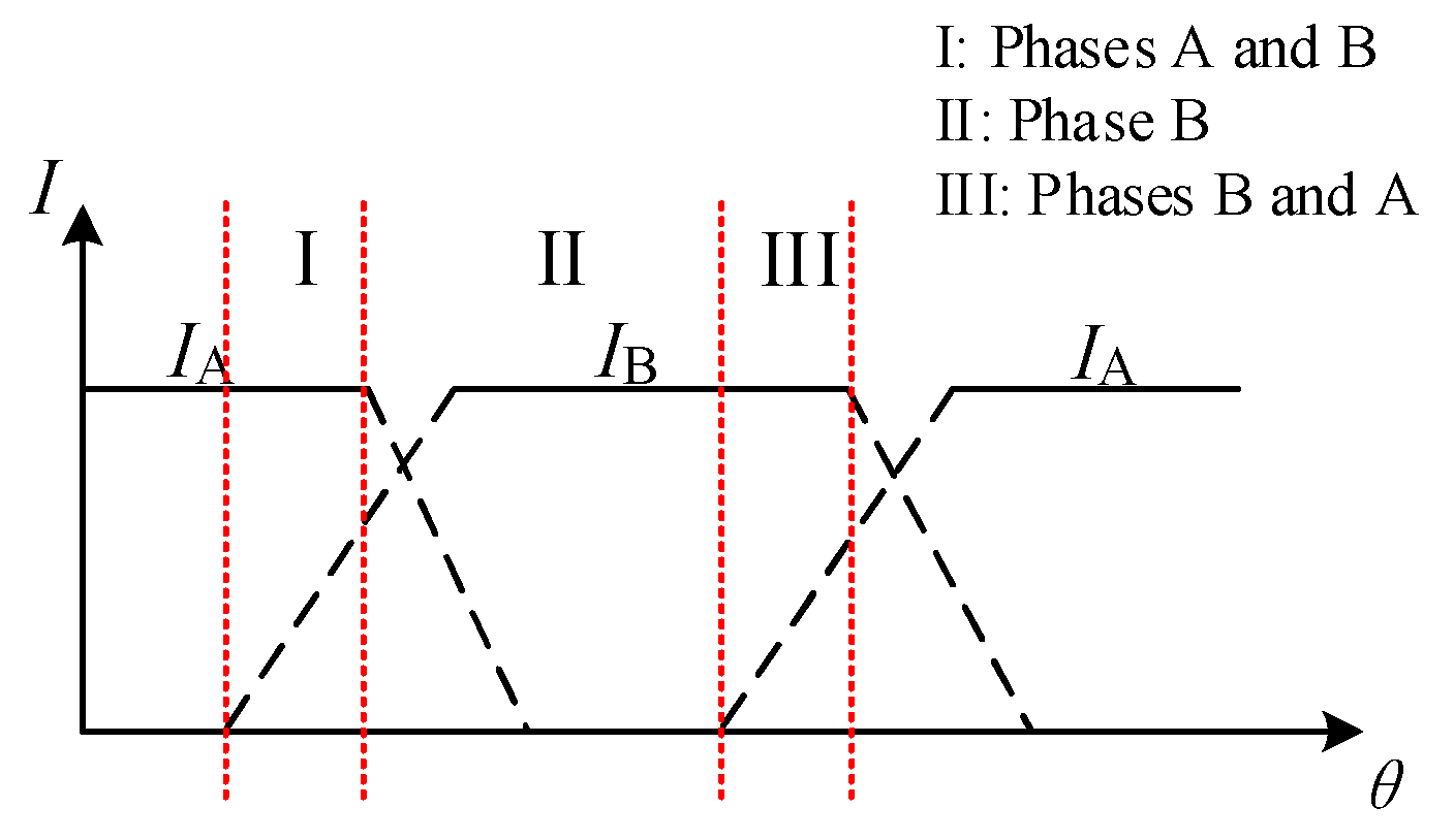
The typical control block of the DITC strategy is shown in Figure 2, which consists of the outer speed loop and the inner torque loop, respectively. The torque hysteresis unit is used to judge the switching signal of the control system by the error of reference torque and instantaneous torque ΔT. Then, select the appropriate switch states to adjust the winding current, thereby controlling the output torque. Figure 3 shows the distribution of the conduction interval, where a working period of phase B can be divided into regions I, II, and III according to the turn-on angle θon and turn-off angle θoff.
3. Sliding Mode Speed Controller
3.1. Advanced Reaching Law
The dynamic and chattering performance of SMC are associated with the design of the reaching law. The system stability can be guaranteed by Lyapunov function if condition (4) is satisfied.
The classical reaching law consisting of isokinetic and pure exponential approach terms can be expressed as follows:
where s is sliding mode surface, ε and k are the switching gain and linear gain, respectively. However, the classical reaching law still suffers from the dilemma of approaching speed and chattering. Thus, an advanced reaching law is designed to accelerate the approaching speed and reduce the chattering simultaneously, as expressed as follows:
where saturation function tanh(s) = (es − e−s)/(es + e−s), x represents the system state quantity, λ > 0, η > 0, 0 < α < 1, β > 0.
It can be seen from the proposed reaching law that the variable gain f(x,s) converges to λ/α when the system state quantity is far away from the sliding mode surface. Therefore, the approaching speed is faster than classical reaching law under the since λ/α is larger than λ. The introduction of in the exponential gain also can obtain less convergence time during the initial approach phase. The variable gain f(x,s) converges to when the motion trajectory approaches the sliding mode surface and the system approaches the origin under the action of the variable gain term. The switching band becomes smaller with the decrease in the state quantity x, thereby suppressing the chattering. Moreover, tanh(s) with a smoother curve is introduced to replace the step function sgn(s) for chattering reduction. In summary, the advanced reaching law can achieve faster approaching speed and lower chattering correspondingly.
To analyze the stability of the reaching law, the Lyapunov function is chosen as , and we find
Due to f(x,s) > 0, stanh(s) ≥ 0, > 0, can be satisfied, which meets the stability condition.
3.2. Design of Speed Controller
Considering the influence of external disturbance, TSMC equipped with finite convergence time is selected to further improve the anti-disturbance ability and robustness. Further, on the basis of the above-advanced reaching law, speed controllers can behave well in speed tracking, dynamic response, torque ripple suppression, and anti-interference capability. To achieve the goal, the speed error and sliding mode surface are described as follows:
where ω* and c are the reference angular speed and positive coefficient, respectively.
Take the derivative of s, we have
Let Te* = T1 + T2, where T1 and T2 are the torque with and without the disturbance, respectively. Substitute (8) and (9) into (3), T1 can be described as follows:
Considering the disturbance caused by the external environment, the following equation can be established by combining (3) and (8).
Select the sliding mode surface s1 as follows:
Differentiate (12) and combine it with (11)
Then, the terminal sliding mode surface z and its first derivative are written as follows:
where μ > 0, m and n are positive odd numbers, and 0 < m < n < 2m.
When the system state reaches the sliding mode surface, z = 0, the following equation is established.
Integrating both sides of (15), we find
where ts represents the finite time from any initial state to the equilibrium point.
Furthermore, substitute (6) into (14)
Combining (13) and (17), T2 can be expressed as follows:
where the disturbance is slowly varying with time, and . Consequently, Te* can be described based on above expressions.
Similarly, is chosen according to stability theory, and then
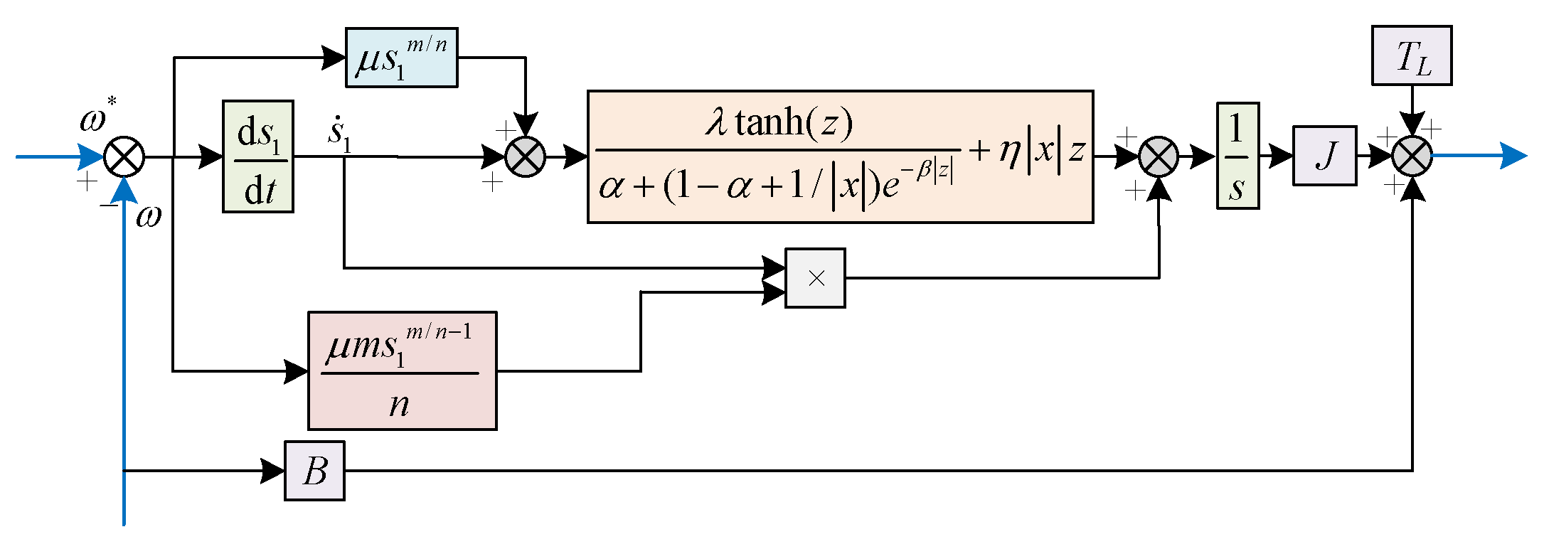
As a result, the stability of the controller can be guaranteed. The schematic diagram of the sliding mode speed controller using advanced reaching law is shown in Figure 4.
4. Optimization of Tunable Parameters with HWOA
4.1. Gray Wolf Optimization
The GWOA simulates the social hierarchy and predation behavior of gray wolves. The gray wolves are a, b, c, and d wolves in descending order in their social hierarchy. Concretely, the positions of a, b, c, and d wolves represent the leader wolf, the deputy wolf, the subordinate wolf, and the bottom wolf, respectively. The mathematical model of the encirclement and hunting behavior is as follows:
where σ and ζ are coefficients, r1 and r2 are random numbers within [0, 1], and γ decreases linearly from 2 to 0 in the iteration process.
where Yz and Y are the position of the prey and the gray wolf, and P is the distance between them. t is the number of iterations, and Yp represents the movement instructions provided by wolves a, b, and c, respectively.
Compared with several swarm intelligent optimization algorithms, such as particle swarm optimization, the GWOA has strong local search capability. Due to few tunable parameters and simple principles, operability and programming are easy. The parallel computation method is adopted in the objective function, resulting in a fast running speed. However, GWOA is easy to fall into the local optimum when solving complex optimization problems. The computational complexity is high since the update is derived from dimensionality calculation.
4.2. Coyotes Optimization Algorithm
The conventional COA contains four main steps: initialization parameters and the wolf pack, growth within the group, birth and death, and the expulsion and acceptance by the group. Different from the GWOA, the COA focuses on social structure and cultural exchange instead of social hierarchy and ruling rules. The improved COA is designed to further enhance the convergence speed and global searching performance. The general steps are grouped into three main steps.
The first step is to set the parameters, including coyote group number Np, number of coyotes in the group Nc, parameter ranges and iterations, and total coyote population N, where N = Np × Nc and Nc > 3. The social condition of each coyote is randomly initialized, and Np and Nc are dynamically tuned for easier operation. Then, group randomly and calculate the social condition of each coyote.
The second step is the growth of coyotes. Concretely, the best coyote, a, in all packs instead of the corresponding pack on the conventional COA can be found, which accelerates the approach speed to the current optimum. The cultural trend of jth pack cultj can be calculated as follows:
where Oj is the sequence of social factors after ranking.
The growth pattern of coyotes can be expressed as follows:
where rh1 and rh2 are the Gaussian numbers, respectively. Compared with the random numbers in conventional COA, the introduction of Gaussian numbers has better global searching performance. and are social conditions of two random coyotes in the jth pack.
The third step is the birth and death of coyotes, and the newborn coyotes are influenced by the inheritance of randomly selected parents and environmental factors, which can be expressed as (28).
where and are the ith dimension of the random coyote r1 and r2, respectively. ri is the random number uniformly distributed in [0, 1], i1 and i2 are two randomly selected dimension labels, Ri is the variation value randomly generated in the ith dimension decision variable range, and Ps and Pu are the dispersion probability and the association probability, respectively.
The COA equipped with a unique search model and structure has excellent optimization ability, especially in dealing with complex optimization situations. Correspondingly, partial defects, including search efficiency, convergence speed, and operability, exist.
4.3. Hybrid Wolf Optimization Algorithm
With the development of the hybrid optimization algorithm, the HWOA combining GWOA and COA is utilized to deal with complex optimization problems. It can be seen that the advantages and drawbacks of the two algorithms compensate for each other. To make up for their respective shortcomings, GWOA and COA are fused together to obtain an HWOA with superior performance and high efficiency. The flow chart of HWOA is shown in Figure 5.
The selection of two optimization algorithms depends on the definition of probability P. Due to the faster convergence speed of GWOA and the strong ability for the local exploration of COA, GWOA, and COA are utilized more frequently in the early part and latter part of iterations, respectively. Hence, their advantages can be fully exploited throughout the entire process of iterative optimization, acquiring better comprehensive performance of optimization algorithm. The P can be designed according to different application requirements, which are set as follows:
Considering the computation time and effect of optimization simultaneously, the parameters related to optimization, such as Np and Nc, are both set as 10. The range of tunable parameters of the designed controller is listed in Table 1, which has been discussed based on the stability of the controller. The optimization objectives mainly include the dynamic performance of speed and torque ripple in this paper. Thus, the objective function is described as follows:
where ; ; n, Ts, Δeω, and Δet are the sampling number, period, angular speed error, and torque error, respectively.
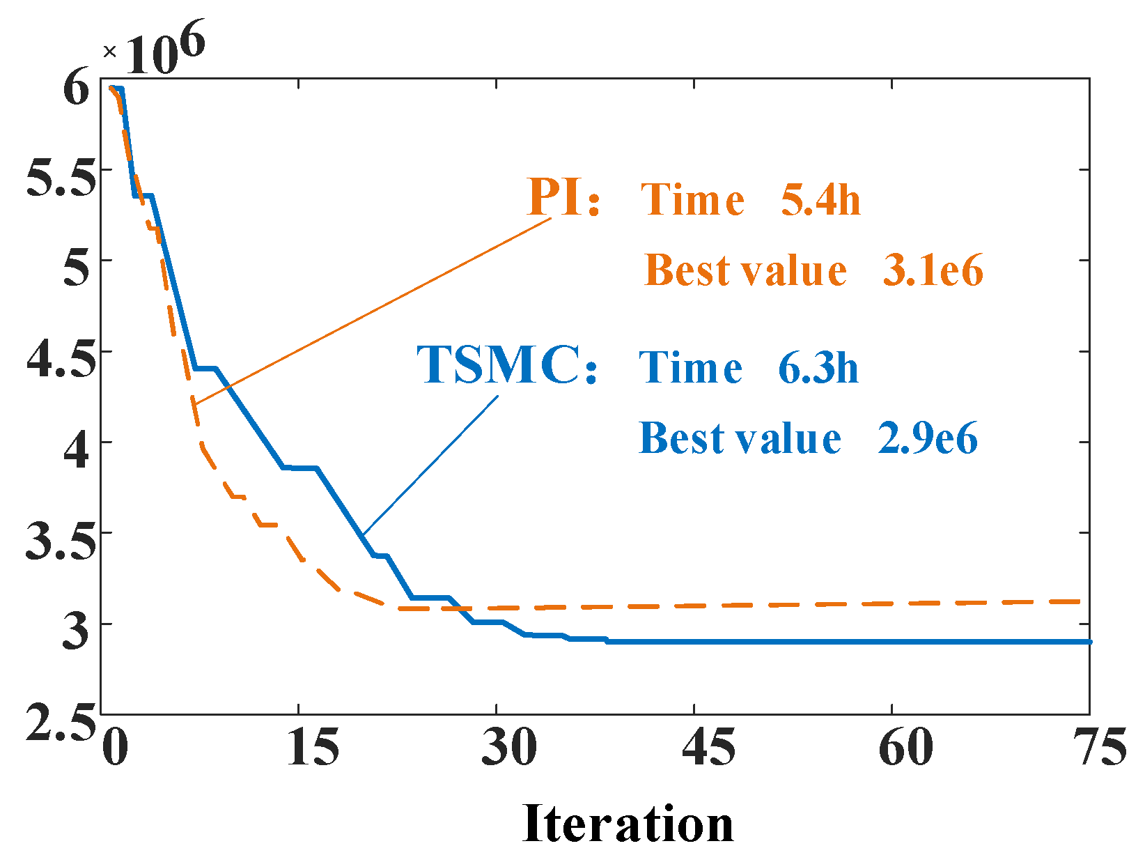
Figure 6 shows the optimization evolution of HWOA, and it can be seen that the fitness value decreases gradually with the increase in iteration numbers. The best fitness values of HWOA are 3.1 × 10⁶ and 2.9 × 10⁶ under 75 iterations for the PI and proposed control scheme. The fitness value changes greatly before the number of iterations reaches 30, and change comes slowly after 30 iterations. The convergence of PI is faster due to fewer tunable parameters.
To prove the superiority of the proposed scheme regarding speed dynamic response, torque ripple reduction and anti-disturbance ability, speed controllers with PI and conventional SMC are selected for comparison. The HWOA is employed to adjust all of the tunable parameters of the three control methods for equitable execution. After simulation optimization, the optimal two parameters of PI are 0.021 and 0.54, respectively. As for proposed TSMC, λ, η, β, μ, α, m, and n are 42.6, 35.7, 3, 51, 0.2, 13, and 15, respectively. Moreover, the values of switching gain ε and linear gain k in SMC are consistent with those of λ and η for comparability. The adjustable parameters optimized by the simulation are applied in the experiments.
5. Experimental Result
The experiment test platform was built to verify the control performance of the advanced DITC scheme, as shown in Figure 7. The entire experimental platform consists of the prototype, a torque and speed sensor, the magnetic power brake, the controller, the power supply, the PC, and an oscilloscope. As shown, the prototype, the torque and speed sensor, and the magnetic power brake are connected by two couplings. The signal obtained by the Hall sensor is sent to the controller; then, the controller outputs switch signals based on the control scheme after compilation. The rated speed and the phase voltage of the motor are 3000 r/min and 24 V, respectively. The main measuring equipment for the speed and torque is listed in Table 2.
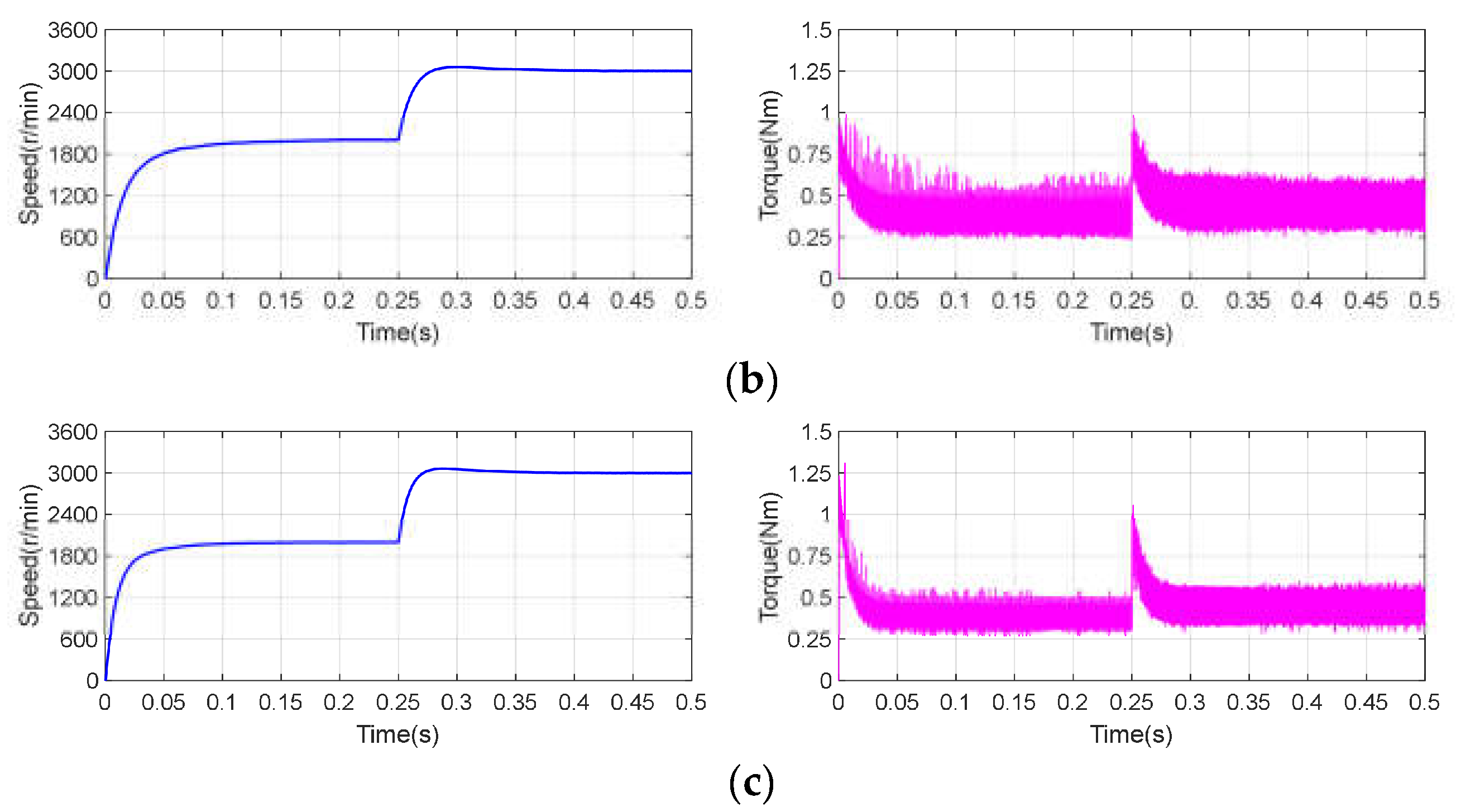
The reference speed and load torque of the motor are set as 3000 r/min and 0.3 Nm, respectively. The experimental results of speed and torque performance using three different controllers applied in the DITC strategy are shown in Figure 8. As shown, the speed transient response of the DITC strategy using the proposed TSMC in the initial stage requires 0.09 s while PI and SMC take 0.18 s and 0.13 s, respectively. It can be reflected that the proposed scheme has less startup time and faster acceleration to reach the steady state, which verifies that the designed reaching law has faster convergence within the limited time. Moreover, the differences between the maximum and minimum torque in the steady state of the three controllers are 0.4 Nm, 0.36 Nm, and 0.3 Nm, respectively. Among them, the torque ripple range of the proposed TSMC can be reduced by 25% and 17%, respectively. It means that the proposed control scheme exhibits the best torque ripple suppression effect, which shows the effectiveness of the proposed reaching law in suppressing chattering. Therefore, the proposed TSMC has superiority in dynamic response and torque ripple reduction under this operation condition, which is consistent with the analytical theory.
Figure 9 illustrates the experimental waveforms of the three controllers in the DITC strategy when the speed changes from 2000 r/min to 3000 r/min at 0.25 s under 0.3 Nm. As shown, the startup time of PI, SMC, and proposed TSMC are 0.2 s, 0.16 s, and 0.12 s, respectively. Consistent with the conclusion of the last condition, the proposed TSMC has the fastest approaching speed. In addition, it takes 0.15 s, 0.12 s, and 0.1 s for PI, SMC, and the proposed TSMC to reach a steady state after the speed change. It can be seen that the speed response of the proposed TSMC can be reduced by 33% and 17% when the speed variation occurs at 0.25 s, respectively. Similarly, the torque ripple reduction effect of the proposed TSMC is the most superior. Meanwhile, as for torque curves, the three schemes all have significant torque oscillations at 0.4 s. The torque ripple range of the three controllers under 800 r/min are 0.34 Nm, 0.32 Nm, and 0.28 Nm, respectively. Among them, the torque ripple range of the proposed TSMC can be reduced by 18% and 13%, respectively. With the change in speed, the torque ripple range in a steady state is not affected significantly. Obviously, the proposed TSMC displays better performance in aspects of speed response and torque ripple reduction under the variable speed condition. It can be found that the same conclusion as the above condition can be obtained, resulting from the advanced reaching law.
Due to the small influence of parameter perturbation, the variable load torque is taken as one of the operating conditions to study the anti-disturbance ability. Figure 10 presents the speed and torque waveforms of PI, SMC, and the proposed TSMC in the DITC strategy when the load torque changes from 0.3 Nm to 0.5 Nm at 0.25 s under 3000 r/min. As shown, the speed overshoot of the proposed TSMC is 140 r/min, while those of PI and SMC are 363 r/min and 269 r/min, respectively. When the load torque changes at 0.25 s, three controllers take about 0.17 s, 0.15 s, and 0.11 s to reach the steady reference speed, respectively. The experimental results indicate that the proposed TSMC shows better anti-disturbance ability and robustness when an external disturbance occurs compared with PI and SMC. The torque ripple ranges in the steady state of PI, SMC, and proposed TSMC are 0.6 Nm, 0.47 Nm, and 0.37 Nm under 0.5 Nm, respectively. Among them, the torque ripple range of the proposed TSMC can be reduced by 38% and 21% compared with those of PI and SMC under variable load torque conditions. It can be clearly seen that the torque ripple range of the proposed method is minimal when the load torque changes. The improvement in terms of lower chattering for modified reaching law can still be guaranteed by introducing variable gain f(x,s) and tanh(s).
For a more intuitive comparison, the experimental results of three controllers under various working conditions are listed in Table 3. In summary, the proposed TSMC can remarkably accelerate the dynamic response, reduce the torque ripple, and improve the anti-disturbance ability and robustness, as shown in the comparison results. The effectiveness of advanced reaching law equipped with faster approaching speed and lower chattering correspondingly is validated from the output performance results under various working conditions.
6. Conclusions
In this paper, an advanced TSMC speed controller applied to the DITC strategy for SRMs was proposed to enhance the dynamic performance, reduce the torque ripple, and improve the anti-disturbance. In the research, an improved reaching law combined with TSMC was designed to accelerate the convergence speed and suppress chattering simultaneously. The load disturbances caused by the external environment can be further suppressed. Furthermore, the HWOA was employed to adjust the tunable parameters for better speed tracking and torque ripple minimization. The superiority of the proposed TSMC in the DITC scheme has been verified under different conditions according to the experimental results. Take the working condition under 3000 r/min and 0.3 Nm as an example, the torque ripple range of the proposed scheme can be reduced by 25% and 17% compared with PI and SMC. Meanwhile, the transient response time can be decreased by 50% and 31%, respectively. In summary, the proposed scheme performs well in speed tracking, dynamic response, torque ripple reduction, and robustness.
In future work, other kinds of control techniques employed in speed controllers, such as active disturbance rejection disturbance, will be investigated and compared. Moreover, real-time optimization of adjustable parameters under different application conditions will be considered for better comprehensive performance.
Funding
This research received no external funding.
Institutional Review Board Statement
Not applicable.
Informed Consent Statement
No applicable.
Data Availability Statement
Not applicable.
Conflicts of Interest
The authors declare no conflict of interest.
Abbreviations
| COA | Coyote optimization algorithm |
| DITC | Direct instantaneous torque control |
| GWOA | Grey wolf optimization algorithm |
| HWOA | Hybrid wolf optimization algorithm |
| SMC | Sliding mode control |
| SRM | Switched reluctance motor |
| TSMC | Terminal sliding mode speed control |
References
- Diao, K.; Sun, X.; Lei, G.; Guo, Y.; Zhu, J. Multimode optimization of switched reluctance machines in hybrid electric vehicles. IEEE Trans. Energy Convers. 2021, 36, 2217–2226. [Google Scholar] [CrossRef]
- Tang, Y.; He, Y.; Wang, F.; Xie, H.; Rodríguez, J.; Kennel, R. A Drive Topology for High-Speed SRM With Bidirectional Energy Flow and Fast Demagnetization Voltage. IEEE Trans. Ind. Electron. 2021, 68, 9242–9253. [Google Scholar] [CrossRef]
- Diao, K.; Sun, X.; Yao, M. Robust-Oriented Optimization of Switched Reluctance Motors Considering Manufacturing Fluctuation. IEEE Trans. Transport. Electrific. 2022, 8, 2853–2861. [Google Scholar] [CrossRef]
- Chen, H.; Fang, C.; Guan, G.; Parspour, N. Fault Diagnosis for Power Converter in SRM Drives Based on Current Prediction. IEEE Trans. Ind. Electron. 2022, 69, 13576–13585. [Google Scholar] [CrossRef]
- Diao, K.; Sun, X.; Bramerdorfer, G.; Cai, Y.; Lei, G.; Chen, L. Design optimization of switched reluctance machines for performance and reliability enhancements: A review. Renew. Sustain. Energy Rev. 2022, 168, 112785. [Google Scholar] [CrossRef]
- Song, S.; Zhang, M.; Ge, L.; Wang, L. Multiobjective optimal design of switched reluctance linear launcher. IEEE Trans. Plasma Sci. 2015, 43, 1339–1345. [Google Scholar] [CrossRef]
- Li, Y.; Lei, G.; Bramerdorfer, G.; Peng, S.; Sun, X.; Zhu, J. Machine Learning for Design Optimization of Electromagnetic Devices: Recent Developments and Future Directions. Appl. Scie. 2021, 11, 1627. [Google Scholar] [CrossRef]
- Sun, X.; Xiong, Y.; Yang, J.; Tian, X. Torque Ripple Reduction for a 12/8 Switched Reluctance Motor Based on a Novel Sliding Mode Control Strategy. IEEE Trans. Transport. Electrific. 2022. [Google Scholar] [CrossRef]
- Rana, A.K.; Raviteja, A.V. A Mathematical Torque Ripple Minimization Technique Based on Nonlinear Modulating Factor for Switched Reluctance Motor Drives. IEEE Trans. Ind. Electron. 2021. [Google Scholar] [CrossRef]
- Sun, X.; Xiong, Y.; Yao, M.; Tang, X. A Hybrid Control Strategy for Multimode Switched Reluctance Motors. IEEE/ASME Trans. Mechatron. 2022, 1–10. [Google Scholar] [CrossRef]
- Xia, Z.; Bilgin, B.; Nalakath, S.; Emadi, A. A New Torque Sharing Function Method for Switched Reluctance Machines With Lower Current Tracking Error. IEEE Trans. Ind. Electron. 2021, 68, 10612–10622. [Google Scholar] [CrossRef]
- Bogusz, P.; Korkosz, M.; Prokop, J.; Daraż, M. Analysis Performance of SRM Based on the Novel Dependent Torque Control Method. Energies 2021, 14, 8203. [Google Scholar] [CrossRef]
- Yan, N.; Cao, X.; Deng, Z. Direct Torque Control for Switched Reluctance Motor to Obtain High Torque–Ampere Ratio. IEEE Trans. Ind. Electron. 2019, 66, 5144–5152. [Google Scholar] [CrossRef]
- Sun, X.; Diao, K.; Lei, G.; Guo, Y.; Zhu, J. Direct torque control based on a fast modeling method for a segmented-rotor switched reluctance motor in HEV application. IEEE J. Emerg. Sel. Top. Power Electron. 2021, 9, 232–241. [Google Scholar] [CrossRef]
- Feng, L.; Sun, X.; Tian, X.; Diao, K. Direct Torque Control With Variable Flux for an SRM Based on Hybrid Optimization Algorithm. IEEE Trans. Power Electron. 2022, 37, 6688–6697. [Google Scholar] [CrossRef]
- Klein-Hessling, A.; Hofmann, A.; De Doncker, R.W. Direct instantaneous torque and force control: A control approach for switched reluctance machines. IET Electr. Power Appl. 2017, 11, 935–943. [Google Scholar] [CrossRef]
- Valencia, D.F.; Tarvirdilu-Asl, R.; Garcia, C.; Rodriguez, J.; Emadi, A. A Review of Predictive Control Techniques for Switched Reluctance Machine Drives. Part I: Fundamentals and Current Control. IEEE Trans. Energy Convers. 2021, 36, 1313–1322. [Google Scholar] [CrossRef]
- Sun, X.; Feng, L.; Diao, K.; Yang, Z. An Improved Direct Instantaneous Torque Control Based on Adaptive Terminal Sliding Mode for a Segmented-Rotor SRM. IEEE Trans. Ind. Electron. 2021, 68, 10569–10579. [Google Scholar] [CrossRef]
- Brauer, H.J.; Hennen, M.D.; Doncker, R.W.D. Control for Polyphase Switched Reluctance Machines to Minimize Torque Ripple and Decrease Ohmic Machine Losses. IEEE Trans. Power Electron. 2012, 27, 370–378. [Google Scholar] [CrossRef]
- Song, S.; Peng, C.; Guo, Z.; Ma, R.; Liu, W. Direct Instantaneous Torque Control of Switched Reluctance Machine Based on Modular Multi-Level Power Converter. In Proceedings of the 2019 22nd International Conference on Electrical Machines and Systems (ICEMS), Harbin, China, 11–14 August 2019; Volume 2019, pp. 1–6. [Google Scholar]
- Yao, S.; Zhang, W. A Simple Strategy for Parameters Identification of SRM Direct Instantaneous Torque Control. IEEE Trans. Power Electron. 2018, 33, 3622–3630. [Google Scholar] [CrossRef]
- Husain, T.; Elrayyah, A.; Sozer, Y.; Husain, I. Unified Control for Switched Reluctance Motors for Wide Speed Operation. IEEE Trans. Ind. Electron. 2019, 66, 3401–3411. [Google Scholar] [CrossRef]
- Zeng, H.; Chen, H.; Shi, J. Direct instantaneous torque control with wide operating range for switched reluctance motors. IET Electr. Power Appl. 2015, 9, 578–585. [Google Scholar] [CrossRef]
- Sun, Q.; Wu, J.; Gan, C. Optimized Direct Instantaneous Torque Control for SRMs With Efficiency Improvement. IEEE Trans. Ind. Electron. 2021, 68, 2072–2082. [Google Scholar] [CrossRef]
- Sun, X.; Tang, X.; Tian, X.; Wu, J.; Zhu, J. Position Sensorless Control of Switched Reluctance Motor Drives Based on a New Sliding Mode Observer Using Fourier Flux Linkage Model. IEEE Trans. Energy Convers. 2021. [Google Scholar] [CrossRef]
- Paula, M.V.d.; Barros, T.A.d.S. A Sliding Mode DITC Cruise Control for SRM With Steepest Descent Minimum Torque Ripple Point Tracking. IEEE Trans. Ind. Electron. 2022, 69, 151–159. [Google Scholar] [CrossRef]
- Barros, T.A.d.S.; Neto, P.J.d.S.; Filho, P.S.N.; Moreira, A.B.; Filho, E.R. An Approach for Switched Reluctance Generator in a Wind Generation System With a Wide Range of Operation Speed. IEEE Trans. Power Electron. 2017, 32, 8277–8292. [Google Scholar] [CrossRef]
- Sun, X.; Wu, J.; Lei, G.; Guo, Y.; Zhu, J. Torque Ripple Reduction of SRM Drive Using Improved Direct Torque Control With Sliding Mode Controller and Observer. IEEE Trans. Ind. Electron. 2021, 68, 9334–9345. [Google Scholar] [CrossRef]
- Scalcon, F.P.; Fang, G.; Vieira, R.P.; Gründling, H.A.; Emadi, A. Discrete-Time Super-Twisting Sliding Mode Current Controller With Fixed Switching Frequency for Switched Reluctance Motors. IEEE Trans. Power Electron. 2022, 37, 3321–3333. [Google Scholar] [CrossRef]
- Paula, M.V.D.; Williamson, S.S.; Barros, T.A.S. Four-Quadrant Model Following Sliding Mode Cruise Control for SRM with DITC applied to Transportation Electrification. IEEE Trans. Transport. Electrific. 2022. [Google Scholar] [CrossRef]
- Azadru, A.; Masoudi, S.; Ghanizadeh, R.; Alemi, P. New adaptive fuzzy sliding mode scheme for speed control of linear switched reluctance motor. IET Electr. Power Appl. 2019, 13, 1141–1149. [Google Scholar] [CrossRef]
- Divandari, M.; Rezaie, B.; Amiri, E. Robust Speed Control of Switched Reluctance Motor Drive Based on Full Order Terminal Sliding Mode Control. In Proceedings of the 2020 IEEE Applied Power Electronics Conference and Exposition (APEC), New Orleans, LA, USA, 15–19 March 2020; Volume 2020, pp. 2423–2428. [Google Scholar]
- Sun, X.; Feng, L.; Zhu, Z.; Lei, G.; Diao, K.; Guo, Y.; Zhu, J. Optimal Design of Terminal Sliding Mode Controller for Direct Torque Control of SRMs. IEEE Trans. Transport. Electrific. 2022, 8, 1445–1453. [Google Scholar] [CrossRef]
- Sharma, P.; Sahoo, B.B. An ANFIS-RSM based modeling and multi-objective optimization of syngas powered dual-fuel engine. Int. J. Hydrogen Energy 2022, 47, 19298–19318. [Google Scholar] [CrossRef]
- Jin, Z.; Sun, X.; Chen, L.; Yang, Z. Robust Multi-Objective Optimization of a 3-Pole Active Magnetic Bearing Based on Combined Curves With Climbing Algorithm. IEEE Trans. Ind. Electron. 2022, 69, 5491–5501. [Google Scholar] [CrossRef]
- Lee, J.H.; Kim, J.W.; Song, J.Y.; Kim, Y.J.; Jung, S.Y. A Novel Memetic Algorithm Using Modified Particle Swarm Optimization and Mesh Adaptive Direct Search for PMSM Design. IEEE Trans. Magn. 2016, 52, 1–4. [Google Scholar] [CrossRef]
- Sun, X.; Hu, C.; Lei, G.; Guo, Y.; Zhu, J. State Feedback Control for a PM Hub Motor Based on Gray Wolf Optimization Algorithm. IEEE Trans. Power Electron. 2020, 35, 1136–1146. [Google Scholar] [CrossRef]
- Mirjalili, S.; Mirjalili, S.M.; Lewis, A. Grey wolf optimizer. Adv. Eng. Softw. 2014, 69, 46–61. [Google Scholar] [CrossRef] [Green Version]
- Huang, C.; Zhuang, J. Error-Based Active Disturbance Rejection Control for Pitch Control of Wind Turbine by Improved Coyote Optimization Algorithm. IEEE Trans. Energy Convers. 2022, 37, 1394–1405. [Google Scholar] [CrossRef]
- Neath, M.J.; Swain, A.K.; Madawala, U.K.; Thrimawithana, D.J. An optimal PID controller for a bidirectional inductive power transfer system using multiobjective genetic algorithm. IEEE Trans. Power Electron. 2013, 29, 1523–1531. [Google Scholar] [CrossRef]
- Tominaga, Y.; Okamoto, Y.; Wakao, S.; Sato, S. Binary-Based Topology Optimization of Magnetostatic Shielding by a Hybrid Evolutionary Algorithm Combining Genetic Algorithm and Extended Compact Genetic Algorithm. IEEE Trans. Magn. 2013, 49, 2093–2096. [Google Scholar] [CrossRef]
- Rajamoorthy, R.; Arunachalam, G.; Kasinathan, P.; Devendiran, R.; Ahmadi, P.; Pandiyan, S.; Muthusamy, S.; Panchal, H.; Kazem, H.A.; Sharma, P. A novel intelligent transport system charging scheduling for electric vehicles using Grey Wolf Optimizer and Sail Fish Optimization algorithms. Energy Sources Part A Recovery Utilization Environ. Effects 2022, 44, 3555–3575. [Google Scholar] [CrossRef]
- Jin, Z.; Sun, X.; Lei, G.; Guo, Y.; Zhu, J. Sliding Mode Direct Torque Control of SPMSMs Based on a Hybrid Wolf Optimization Algorithm. IEEE Trans. Ind. Electron. 2022, 69, 4534–4544. [Google Scholar] [CrossRef]
Figure 1.
The structure and prototype.

Figure 2.
The control block of DITC strategy.

Figure 3.
The distribution of conduction interval.

Figure 4.
Schematic diagram of speed controller.

Figure 5.
Flow chart of HWOA.

Figure 6.
Optimization evolution of HWOA.

Figure 7.
Experiment test platform.

Figure 8.
Experimental results under 0.3 Nm. (a) PI, (b) SMC, and (c) proposed TSMC.

Figure 9.
Experimental results under speed change. (a) PI, (b) SMC, and (c) proposed TSMC.


Figure 10.
Experimental results under load torque change. (a) PI, (b) SMC, and (c) proposed TSMC.


Table 1.
Setting and parameters range of optimization.
| Parameters | Value |
|---|---|
| Np, Nc | 10 |
| α, m/n | [0, 1] |
| λ, η, β, μ | [1 × 10⁻³, 1 × 10⁶] |
Table 2.
Main measuring equipment.
| Equipment | Type | Measuring Range | Measuring Error |
|---|---|---|---|
| Torque sensor | JN338 | 20 Nm | 0.2% |
| Speed sensor | JN338 | 18,000 r/min | 0.5% |
| Magnetic power brake | PB-A-1.2 | 12 Nm | 1% |
Table 3.
Experimental results of three controllers.
| Condition | Parameters | PI | SMC | TSMC |
|---|---|---|---|---|
| Constant load torque | Startup time | 0.18 s | 0.13 s | 0.09 s |
| Torque ripple range | 0.4 Nm | 0.36 Nm | 0.3 Nm | |
| Speed change | Startup time | 0.2 s | 0.16 s | 0.12 s |
| Response time | 0.15 s | 0.12 s | 0.1 s | |
| Load torque disturbance | Response time | 0.17 s | 0.15 s | 0.11 s |
| Speed overshoot | 363 r/min | 269 r/min | 140 r/min | |
| Torque ripple range | 0.6 Nm | 0.47 Nm | 0.37 Nm |
Publisher’s Note: MDPI stays neutral with regard to jurisdictional claims in published maps and institutional affiliations. |
© 2022 by the author. Licensee MDPI, Basel, Switzerland. This article is an open access article distributed under the terms and conditions of the Creative Commons Attribution (CC BY) license (https://creativecommons.org/licenses/by/4.0/).
Share and Cite
MDPI and ACS Style
Yin, Y. Optimal Direct Instantaneous Torque Control for SRMs Using Advanced Sliding Mode Controller. Appl. Sci. 2022, 12, 12177. https://doi.org/10.3390/app122312177
AMA Style
Yin Y. Optimal Direct Instantaneous Torque Control for SRMs Using Advanced Sliding Mode Controller. Applied Sciences. 2022; 12(23):12177. https://doi.org/10.3390/app122312177
Chicago/Turabian StyleYin, Yonghua. 2022. "Optimal Direct Instantaneous Torque Control for SRMs Using Advanced Sliding Mode Controller" Applied Sciences 12, no. 23: 12177. https://doi.org/10.3390/app122312177
Note that from the first issue of 2016, this journal uses article numbers instead of page numbers. See further details here.