Article

Influence of the Main Geometrical Parameters on the Design and Performance of Mixed Inflow Turbines

1
FERTIAL SPA Company, Industrial Zone SPA BP 40, Arzew 31200, Algeria
2
Department of Mechanical Engineering Technology and Metal-Cutting Machines, National Technical University “Kharkiv Polytechnic Institute”, 2, Kyrpychova St., 61002 Kharkiv, Ukraine
3
Department of Industrial Engineering and Management, Faculty of Mechanical Engineering, University of West Bohemia, 301 00 Plzen, Czech Republic
4
Department of Power System Engineering, Faculty of Mechanical Engineering, University of West Bohemia, 301 00 Plzen, Czech Republic
5
MEtRICs Research Center, Campus of Azurém, University of Minho, 4800-058 Guimarães, Portugal
*
Author to whom correspondence should be addressed.
Appl. Sci. 2022, 12(23), 12165; https://doi.org/10.3390/app122312165
Submission received: 29 October 2022 / Revised: 24 November 2022 / Accepted: 24 November 2022 / Published: 28 November 2022
(This article belongs to the Topic Advanced Systems Engineering: Theory and Applications)

Abstract

:

Featured Application

This study consists of a contribution to the design of mixed inflow turbines with the view to improve their performance when integrated in internal combustion engines.

Abstract

The blade shape is of great interest to hybrid turbine designers, due to its significant and direct impact on turbine performance. The inlet and outlet diameters of the vane affect the size of the rotor, which is limited because of the small space available in internal combustion engines. The effect of the ratio of the average inlet diameter and the average exducer inlet diameter on the performance of a mixed inlet turbine will be the focus of this study, which consists of two cases included herein for the purpose of illustrating the means of improving rotor performances and controlling the flow mass rate. In the first case, we achieved this by changing the average diameter of the exducer inlet, while, in the second one, we achieved this by changing the average inlet diameter. Additionally, the angles of the inlet and outlet blades were recalculated to preserve the same blade profile and to eliminate the effect of curvilinearity. It was noted that the shape of the blade was very sensitive to changes in the ratio of the investigated diameters, and—in both cases—interesting results were obtained. First, an increase in output work and in total static isentropic efficiency by 2.16% and 2.15%, respectively, was generated, with a saving of 3.52% of the used mass flow and a lighter rotor compared to one that used to take up the same space by using fixed average inlet diameter blades. In the second case, there was an increase in the output work by 3.31%, and in the total static isentropic efficiency by 3.34%, but the rotor became heavier and required an increase in the mass flow used. Since inter-blade flows are very complex, three-dimensional and viscous—featuring various types of secondary and eddy flows—the CFX.15-CFD code was used in all models to solve the averaged Navier–Stokes equations.

1. Introduction

The issues of intensifying technological processes and increasing the efficiency of mixed-flow turbines, which are important components of internal combustion engines, are a priority in modern mechanical engineering. The peculiarity of such turbines lies in the simultaneous presence of an axial and a radial flow, with none of these flows being negligible.
To increase the power of an engine, the quantity of air and fuel admitted into the combustion chamber must be increased. For this purpose, turbocharging is used—a technique that uses a turbocharger for the purpose of expanding the exhaust gases along a mixed or radial turbine to drive them to a centrifugal compressor interposed between the air inlet and the intake manifolds. In this process, a heat exchanger (an intercooler) is generally added to lower the temperature.
In this light, due to the great importance of using mixed and radial inflows turbines in the internal combustion engine field to raise their energy, they have attracted the attention of many researchers who are trying to find ways to improve their performance.
To this end, Sawada et al. [1] presented a method of performance estimation for radial inflow turbines by basing the analysis on the so-called one-dimensional flow.
Other, such as Milton et al. [2] studied the effect of reducing rotor blade inlet diameter on turbine performance. The results of this investigation indicated that maximum efficiencies were obtained with a Clearance ratio of 0.075 for the turbine, in which case the Clearance ratio was defined as the difference between the diameter at the stator blade trailing edge and the rotor blade inlet diameter divided by the diameter at the stator blade trailing edge.
Other authors also had important contributions. Baines [3] presented the development of the primary and secondary flows in the rotors of radial-inflow turbines. Richard [4] studied radial turbine cooling to produce high specific work output at safe rotor stress levels. Anthony [5] designed and tested a small, high-pressure ratio radial turbine and described the aerodynamic rotor design. Takamura et al. [6] analyzed the influence of blade aerodynamic loading on the efficiency of the radial-inflow turbine. Chen et al. [7] studied the effect of blade loading in radial and mixed-flow turbines. Rodgers [8] analyzed the aerothermodynamic, structural, and economic factors which influence the performances of small gas turbines in the 50–100 kw class. Wallace et al. [9] developed a unified approach to the one-dimensional analysis and design of radial and mixed-flow turbines. Carlos et al. [10] realized a preliminary design and performance estimation of a radial inflow turbine (an automated approach). Zeng et al. [11] studied the effects of the squealer geometry of the turbine blade tip on the tip leakage flow and loss. Pesiridis et al. [12] analyzed an experimental evaluation of active flow control mixed-flow turbines for automotive turbocharger applications. Copeland et al. [13] combined experimental and computational results to study the various timescales associated with pulsed turbine operation. Hagen et al. [14] presented equation-oriented methods for the design optimization and performance analysis of radial inflow turbines. Dadone et al. [15] clarified a method for evaluating the off-design performance of a radial inflow turbine with comparison experiments. Wasserbauer et al. [16] programmed the Fortran program for predicting the off-design performance of radial-inflow turbines. Rodgers [17] established an advanced radial inflow turbine rotor program design with dynamic testing and studied direct conduction cooling at turbine inlet temperatures from 1478 K (2660°R) to 1700 K (3060°R). Lauriau et al. [18] implemented preliminary design considerations for variable geometry radial turbines with multipoint specifications. Alawadhi et al. [19] studied the design and optimization of a radial turbine to be used in a Rankine cycle operating with an OTEC System. Zahed et al. [20] presented the radial turbine design process. Rodgers [21] studied radial turbine-blade number and reaction effects. Doran et al. [22] presented an experimental performance evaluation of a 99.0 mm radial inflow nozzle turbine with varying shroud profiles; the results have helped to confirm some of the trends noted in the earlier tests. Gao et al. [23] validated a mean line performance prediction method for radial and mixed-flow turbines. Palfreyman et al. [24] carried out a numerical study of the internal flow field characteristics in mixed flow turbines. Chou et al. [25] treated the design and testing of a mixed-flow turbine for turbochargers. Minegishi et al. [26] developed a small mixed-flow turbine for automotive turbochargers. Wallace et al. [27] presented a design construction and testing of a mixed-flow gas turbine. Rajoo et al. [28] examined an experimental study on the performance of a variable geometry mixed flow turbine for an automotive turbocharger. Pesiridis et al. [29,30,31] realized an experimental evaluation of an active flow control mixed-flow turbine for automotive turbocharger applications. Lee et al. [32] analyzed a tilted turbine housing volute design under pulsating inlet conditions, and Ketata et al. [33] examined a numerical study of a vanned mixed flow turbine operating in various steady flow conditions. Ali et al. [34] studied the number of blade effects on the performance of a mixed turbine rotor, and Meghnine et al. [35] presented the influence of the volute cross-sectional shape on mixed inflow turbine performances. Hamel et al. [36] investigated a twin entry mixed flow turbine volute and its benefits for the eco-system. Morrison et al. [37] demonstrated the effects of flow conditions at the rotor inlet on mixed-flow turbine performance for automotive applications; Padzillah et al. [38] analyzed an experimental and numerical investigation of flow angle characteristics of an automotive mixed-flow turbocharger turbine. Udayakumar et al. [39] presented the impact of mixed-flow turbines on the efficiency of automotive turbocharger applications. Karamanis [40] examined the steady and unsteady performance of mixed-flow turbines for automotive turbochargers. Zhang et al. [41] created a 3D inverse design method for the optimization of radial and mixed-inflow turbines. Leonard et al. [42] analyzed the design and performance of mixed-flow turbine rotors with extended blade chords. Chelabi et al. [43,44,45] studied the effects of the cone, inlet, and deviation blade angles on mixed inflow turbine performances and analyzed the three-dimensional accelerating flow in a mixed turbine rotor. A smaller number of blades was suggested for a cone angle of 20° in the case of parallel surfaces [43] because of parameters, such as a large surface, weight, inertia, and a wide range of operation, for maximum efficiency. Also, the machine experienced [44] a 3.71% and 3.67% increase in work output and efficiency, respectively. It has been established [45] that for larger absolute exit kinetic energies, for values of deviation blade angle between −10° and −20°, an exhaust diffuser is recommended to recover a part of it into a greater expansion ratio. Kononenko et al. [46] examined the deflections and frequency in the milling of thin-walled parts with variable low stiffness; Dobrotvorskiy et al. [47] developed an optimum thin-walled parts milling parameters calculation technique.
This study will present the effect of inlet average diameter to exducer mean root diameter ratio on mixed inflow turbine performances in two cases. The first is by fixing the average inlet diameter and the second is by fixing the average exducer root diameter while preserving:
  • The same ratio values for the two cases discussed.
  • The same dawn profile needed to eliminate the effect of the camberline shape on the turbine performance, resulting in the need to calculate the new outlet blade angles in the first case and the inlet blade angle in the second case.
  • The inlet and outlet blade height needed to eliminate the flow convergence effect at 2d, resulting in the need to calculate the new hub and shroud radius at the outlet in the first case, and the new hub and shroud radius at the inlet in the second case.

2. Materials and Methods

Due to the complexity and importance of the blade shape and its impact on the turbine’s efficiency, it is necessary to use an easy mathematical model that enables control of all angles and dimensions of the blade. To this end, we used the Bezier polynomial model of four degrees to determine the meridian plane and the camberline profile.

2.1. Initial Rotor Design

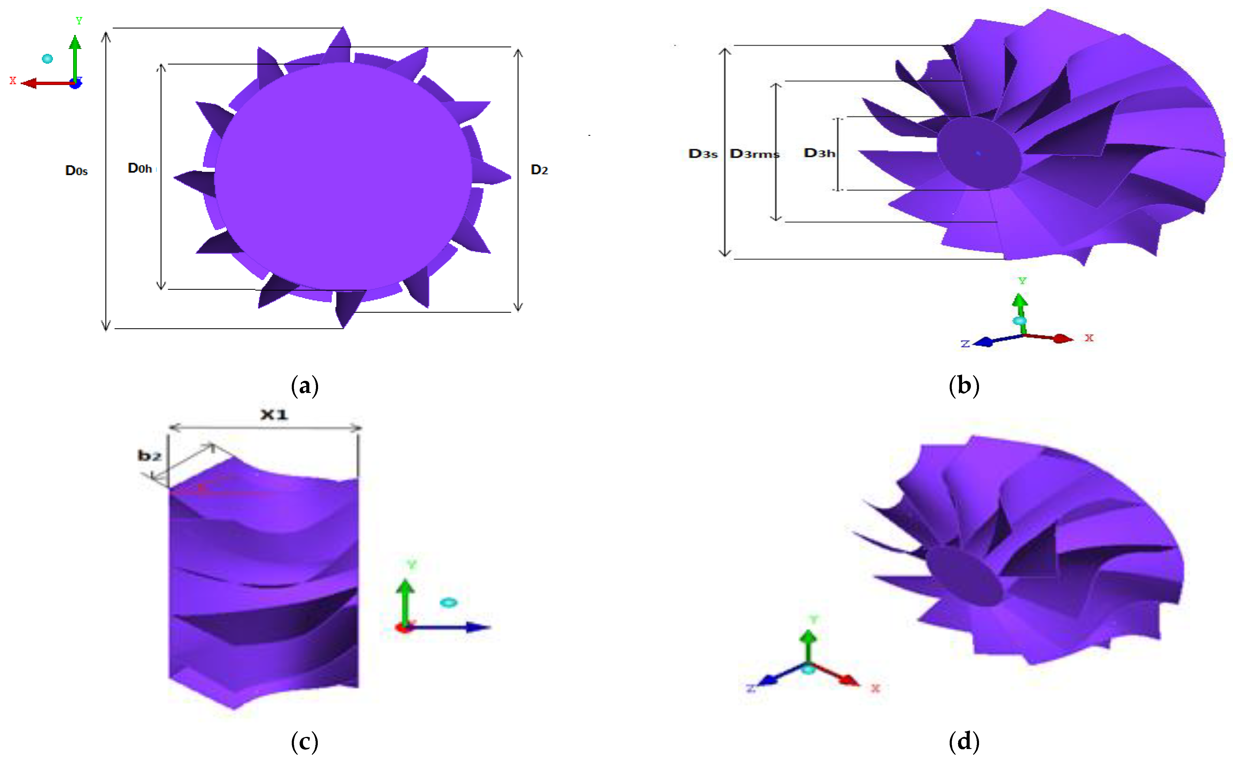
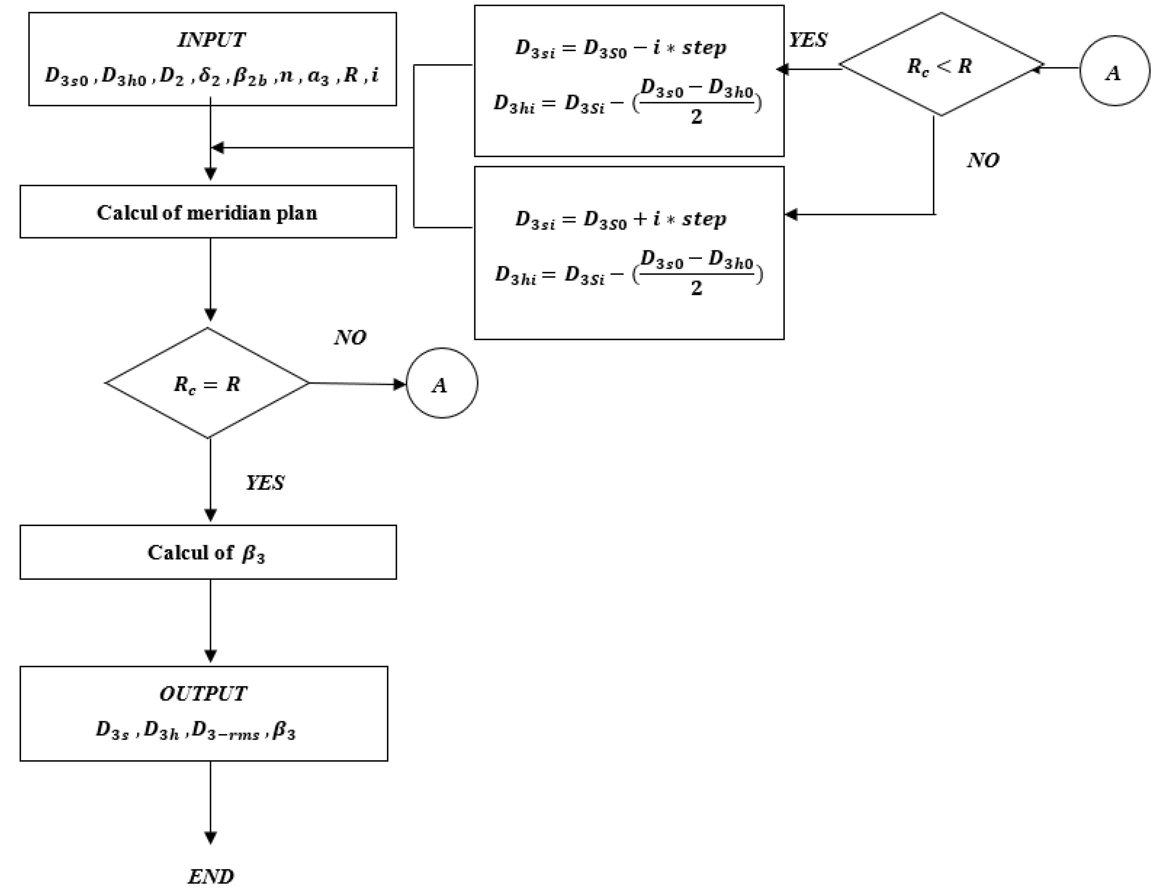
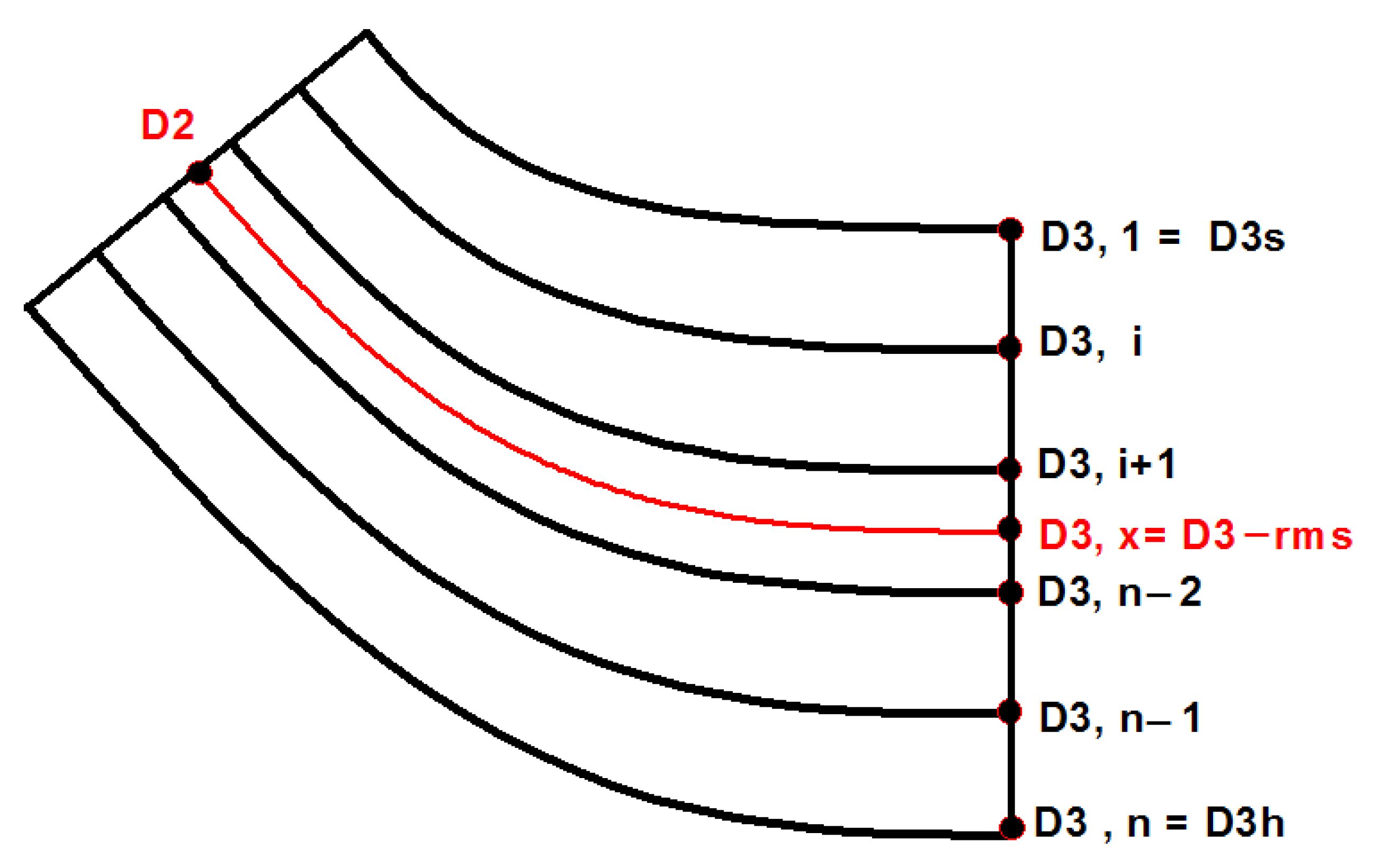
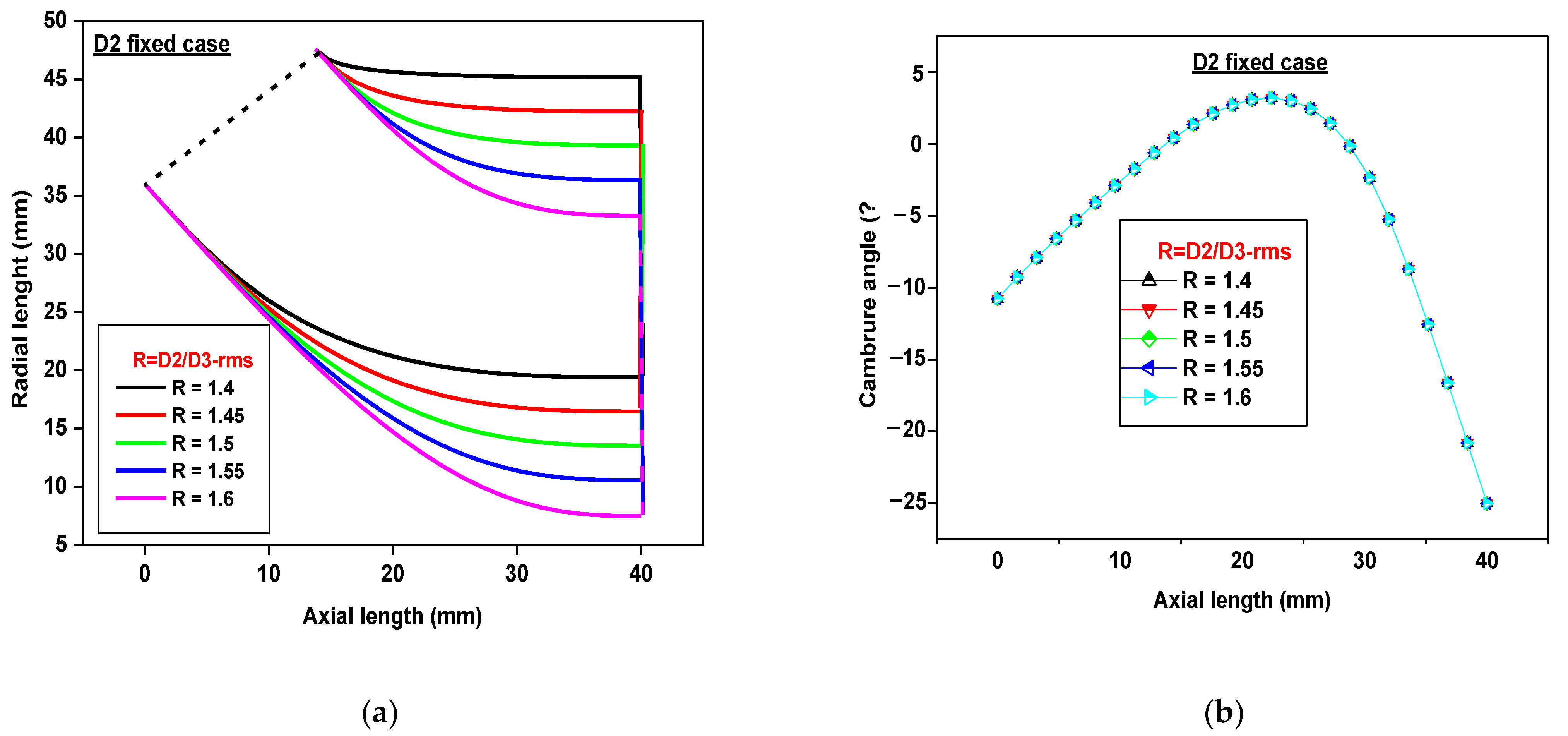
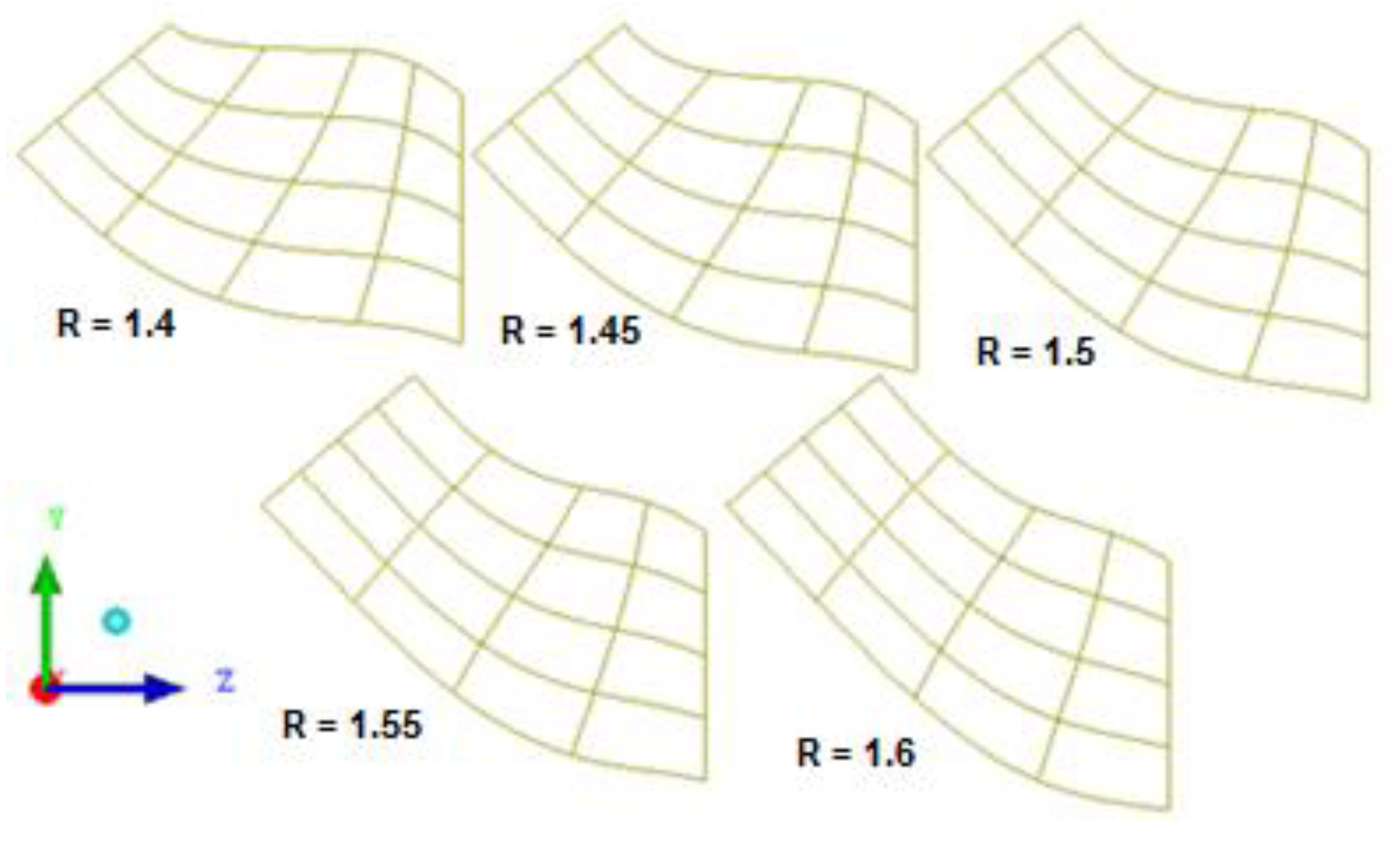
2.1.1. Meridian Plane

The blade meridian plane (Figure 1) is characterized by its shroud and hub profiles; the relations below of the Bezier polynomial are respected (Equations (1) and (2)) to determine de meridional plan:
r = ( 1 u ) 4 r 0 + 4 u ( 1 u ) 3 r 1 + 6 u 2 ( 1 u ) 2 r c + 4 u 3 ( 1 u ) r 2 + u 4 r 3 ,
x = ( 1 u ) 4 x 0 + 4 u ( 1 u ) 3 x 1 + 6 u 2 ( 1 u ) 2 x c + 4 u 3 ( 1 u ) x 2 + u 4 x 3
where u is acoefficient between 0 and 1.
For the hub, the items of 0 and 3 are defined as follows (Equations (3) and (4)):
x 0 = 0 ;   r 0 = 1 2 ( D 2 b 2 s i n ( δ 2 ) ) ,
x 3 = X 1 ;   r 3 = 1 2 D 3 h .
and, for the shroud, the items of 0 and 3 are defined as follows (Equations (5) and (6)):
x 0 = b 2 c o s ( δ 2 ) ;   r 0 = 1 2 ( D 2 + b 2 s i n ( δ 2 ) )
x 3 = X 1 ;   r 3 = 1 2 D 3 s .

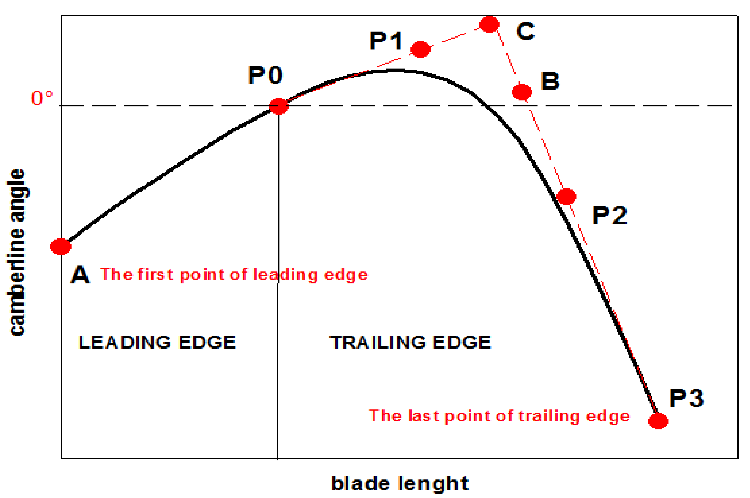
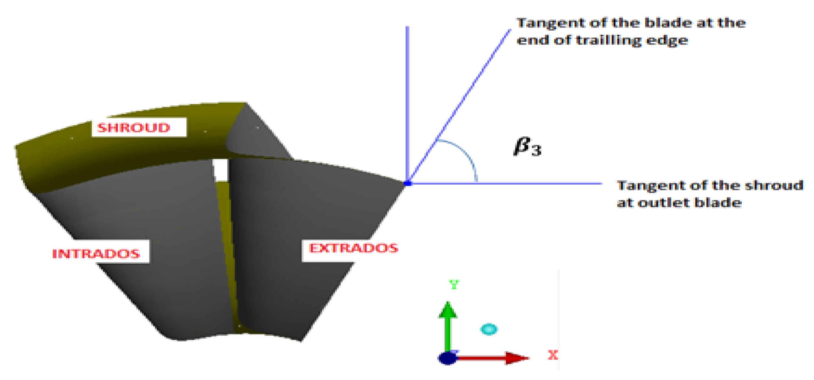
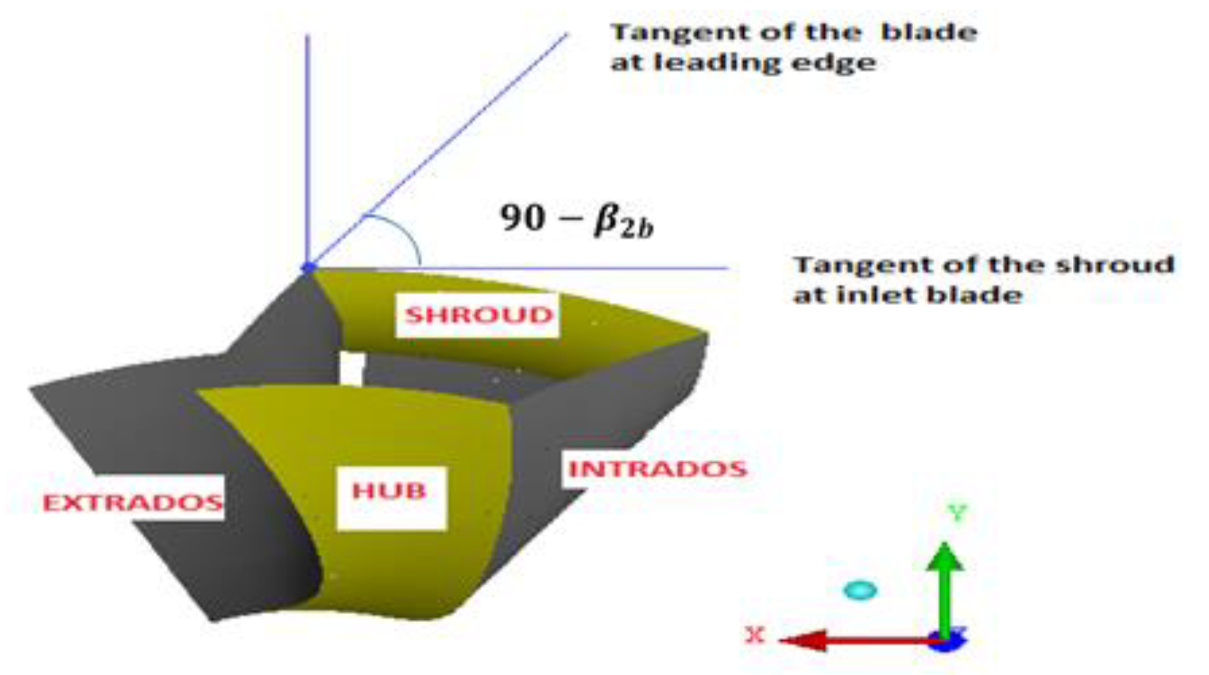
2.1.2. Camberline Profile

The camberline consists of a leading edge and a trailing edge; the first one is obtained based on the following relations (Equations (7) and (8)):
θ = θ r e f + 1 sin ( δ 2 ) x r e f x tan ( β 2 b ) d x r ,
r = r 0 h + ( x x 0 h ) tan ( δ 2 ) .
The rotor type A has a constant blade angle, and by merging Equations (7) and (8), the equation of the leading edge camberline becomes (Equation (9)):
θ = θ r e f + tan ( β 2 b ) s i n ( δ 2 )   tan ( δ 2 )   L n [ ( r 0 h   x 0 h   tan ( δ 2 ) ) + x   tan ( δ 2 )     ( r 0 h   x 0 h   tan ( δ 2 ) ) + x r e f   tan ( δ 2 )   ] .
To complete the remainder of the camberline, it is necessary to calculate the trailing edge profile (Figure 2); this is where the Bezier polynomial is used. The following formulas are applied (Equations (10) and (11)):
x = ( 1 u ) 4 x 0 + 4 u ( 1 u ) 3 x 1 + 6 u 2 ( 1 u ) 2 x b + 4 u 3 ( 1 u ) x 2 + u 4 x 3 ,
θ = ( 1 u ) 4 θ 0 + 4 u ( 1 u ) 3 θ 1 + 6 u 2 ( 1 u ) 2 θ b + 4 u 3 ( 1 u ) θ 2 + u 4 θ 3 .

2.2. Numerical Simulation

2.2.1. Numerical Method Applied

The task of obtaining solutions to the governing equations of turbomachinery flow represents one of the most challenging problems in science and research. In most instances, the mathematical formulation equations of the momentum, continuity, and energy are expressed as partial differential equations (PDE). Second-order partial differential equations—which must be solved within an irregular domain subject to various initial and boundary conditions—arise frequently. In general, these equations do not admit analytical solutions, except in very simplified cases. Therefore, resorting to digital resolution methods called CFD is necessary. The ANSYS-CFD is used in this project—where it is based on the finite volume methods in its calculation—because it is well suited to conservative problems. The first stage is to identify discrete locations (that generate a grid), in which the variables are to be calculated and defined by the numerical grid—which is essentially a discrete representation of the geometric domain on which the problem is to be solved. It divides the solution domain into a finite number of subdomains. This study used the unstructured hexahedral grid because it adapts well to turbomachine simulations. In the second and the final stages, the transport equations are solved after simplifying them in line with the nature of the flow. To reach more precise results, the grid corresponding to the surface located in the vicinity of the walls of the object were refined to obtain more exact thermodynamic results.

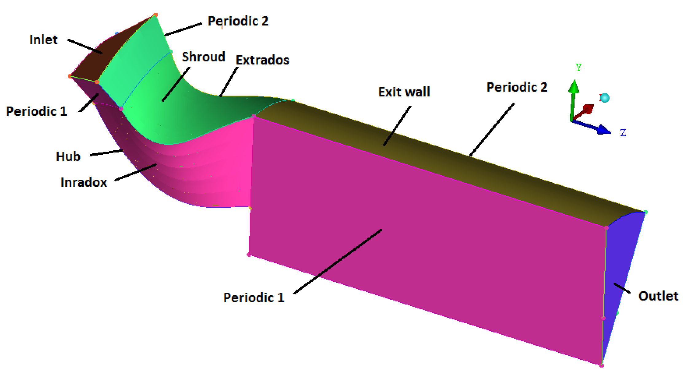
2.2.2. Boundary Conditions

The rotor type A of a mixed inflow turbine (with a constant inlet blade angle) with dimensions recorded in Table 1 is under examination in this section. The general calculation conditions applicable are summarized as follows: the simulation domain was an inter-blading channel (as per the periodicity condition), the mesh used was an unstructured one in the shape of a hexahedron, the fluid used was an ideal air gas (ideal gas), the conditions at the channel inlet were the total pressure of 2.91 bars, the total temperature was 920 °K, and the absolute flow angle was −13°. The conditions at the channel outlet included the static pressure of 1 bar, the rotation speed of 98,000 rpm and the use of k-ε was a model of turbulence. In Figure 3, the different geometrical zones are regrouped and depicted.

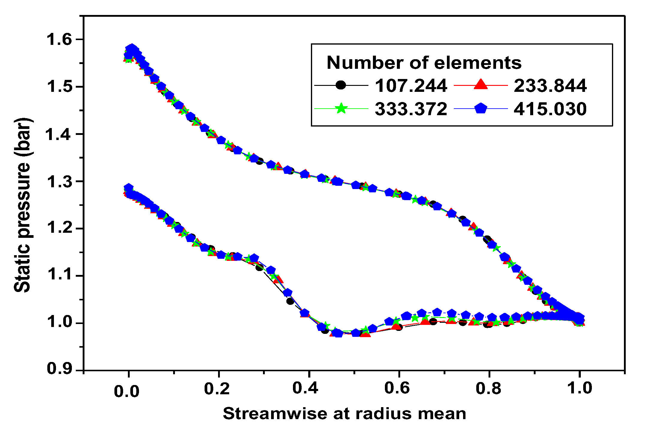
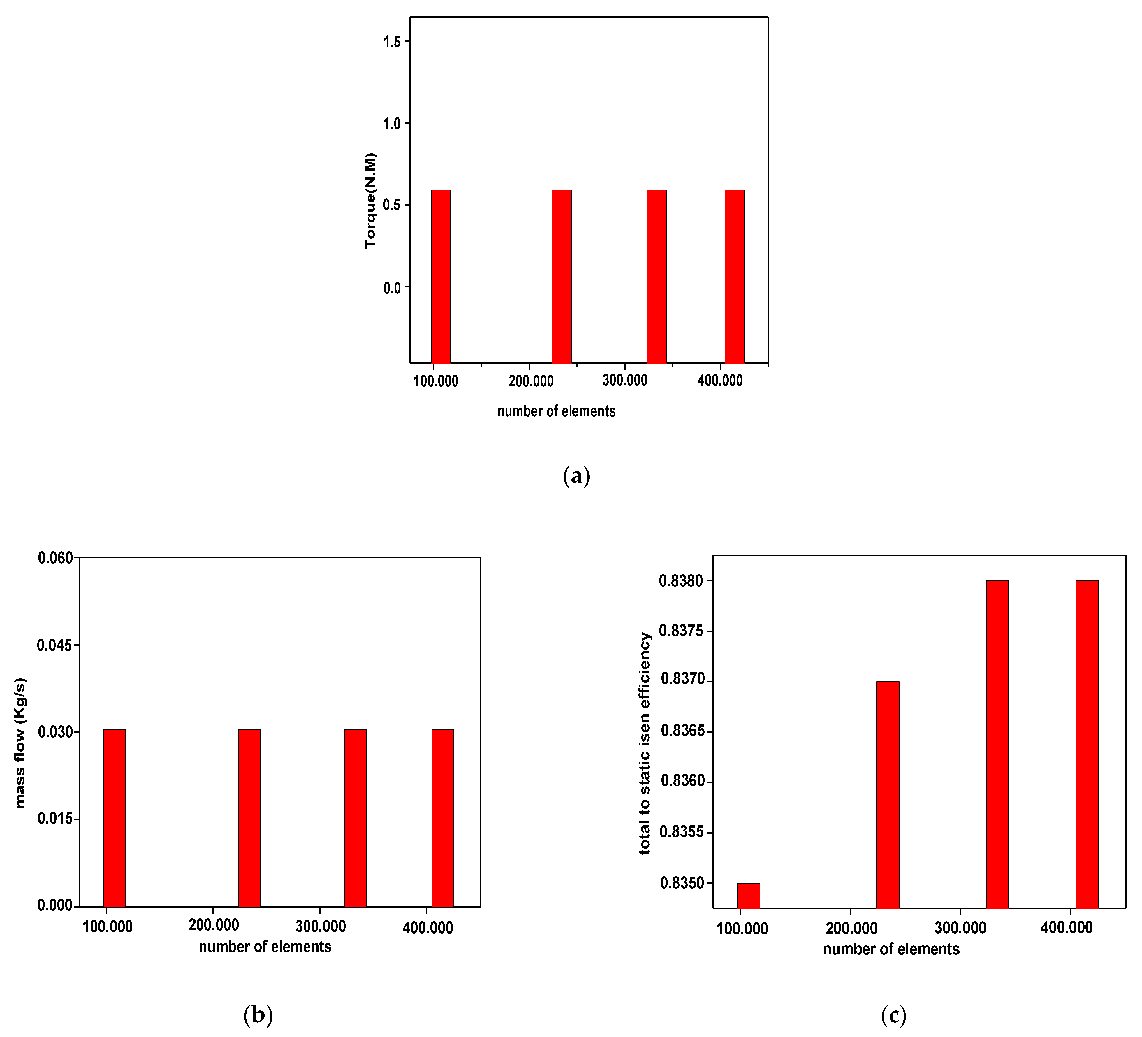
2.2.3. Grid Solution Dependency

To find the optimal grid condition that indicated the smallest number of elements without generating a difference in the numerical results based on the evaluation of various grid conditions, grid independence was mandatory. Four grids of 107,244, 233,844, 333,372, and 415,030 elements were examined for the rotor type A. The analysis of the graphs revealed that the number of elements did not have any effect on the parameters of torque and the mass flow rates (Figure 4). The report also noted a negligible impact on the static pressure distribution around the rotor blade (Figure 5a,b). The efficiency graph reached stability at 333,372 elements. According to this indicator, the grid parameter corresponded to 333,372 elements—which were then applied in the numerical simulations.

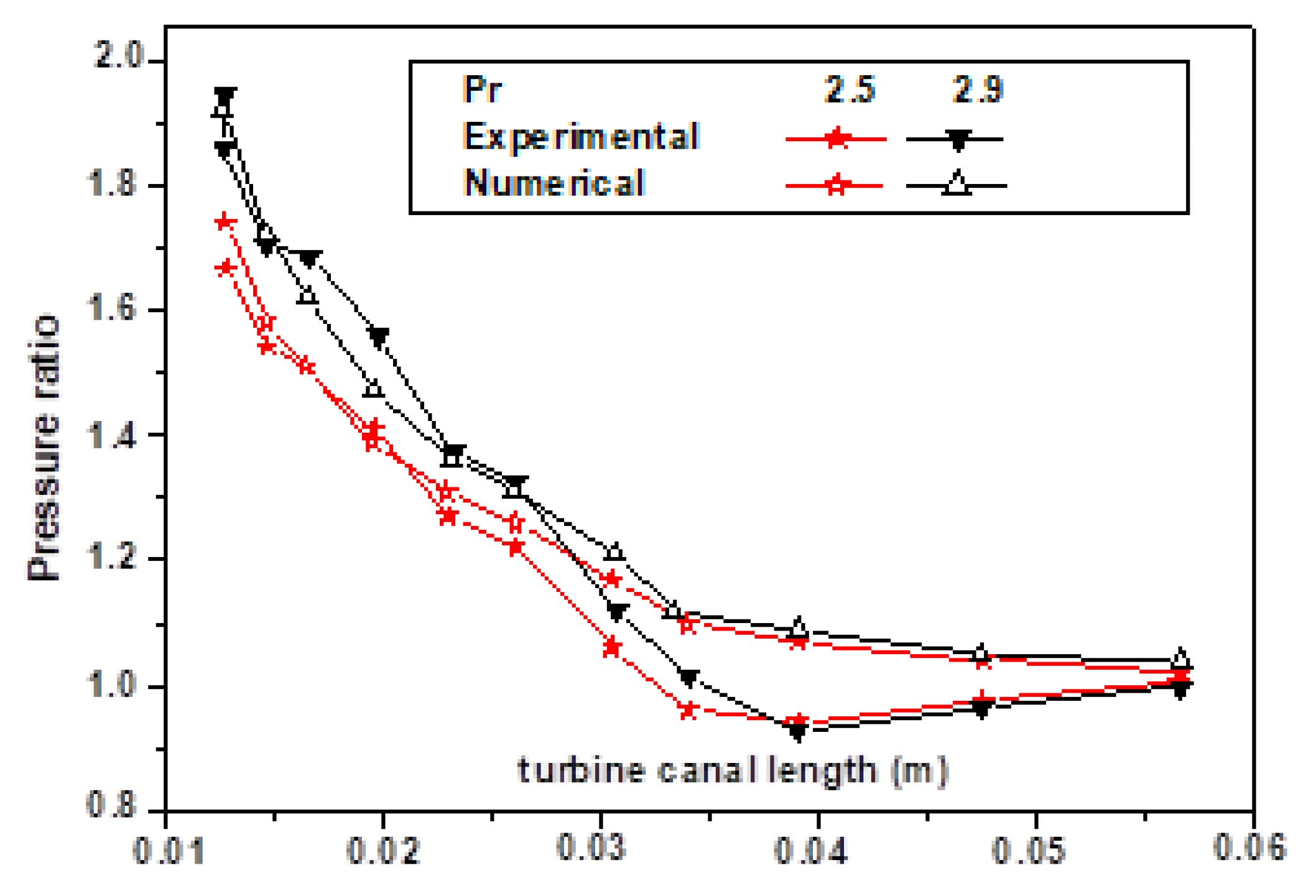
2.2.4. Numerical Model Validations

The used numerical model was validated by the experimental work of Chen and Abidet [7], who found an agreement between the experimental and numerical results (Figure 6).
Below, the expansion pressure ratio defined as the inlet stagnation pressure over the exit static pressure was represented along the blade axial direction.

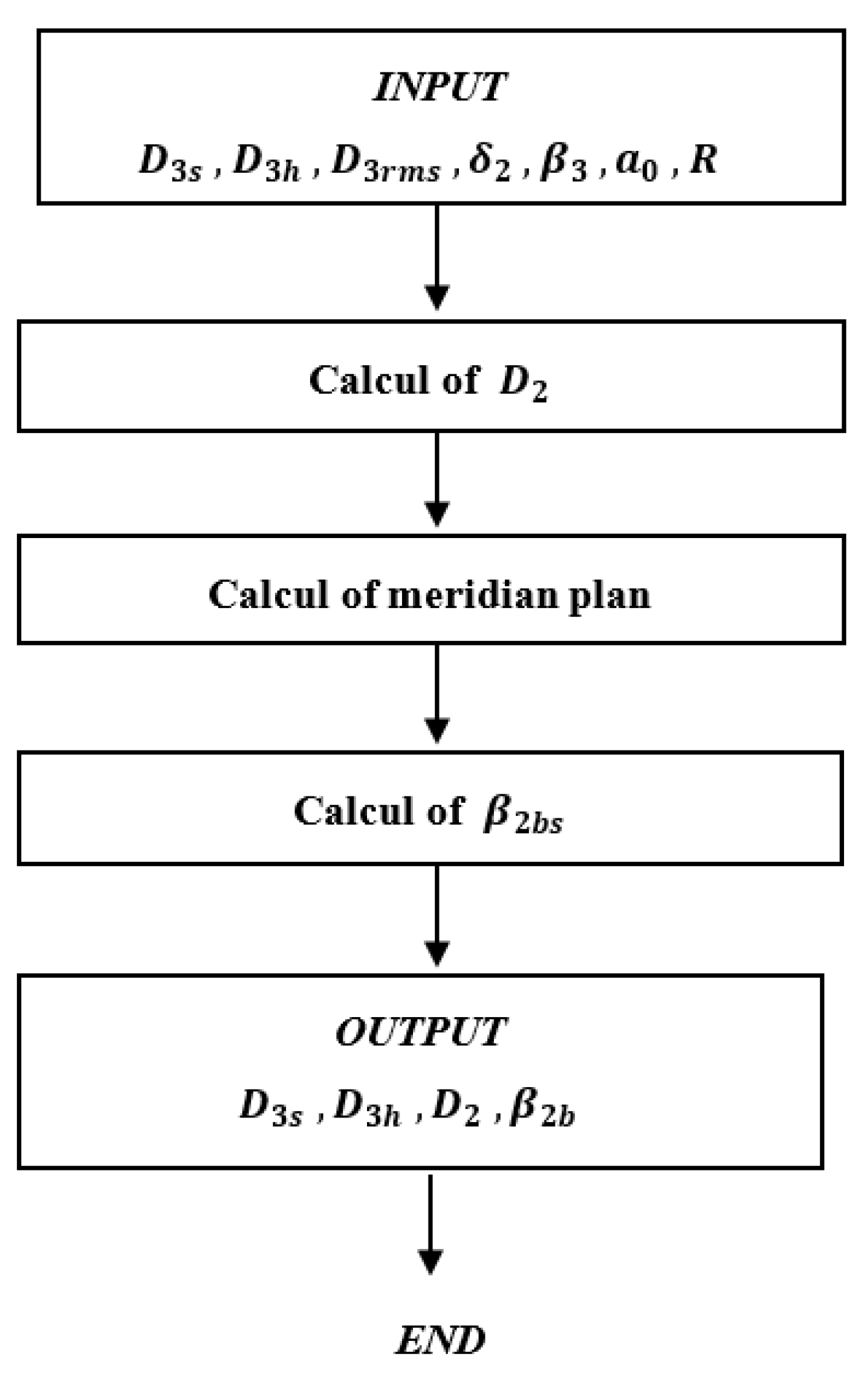
2.3. New Design Theory

It is known that the shape of the rotor is important in the design process of a mixed-flow turbine because it affects the efficiency of the turbocharger. However, the space occupied by the structure is also important because of the difficulty in accommodating a large structure in the internal combustion engine structure. The influence of the ratio between the average diameter of the inlet and the average diameter of the outlet pipe on the characteristics of the mixed turbine is investigated in the two cases illustrated below.

2.3.1. A Fixed Value of the Inlet Means Diameter Case

In the first stage of research, the average inlet diameter was chosen as constant, and the average diameter of the exducer root varied. In this stage, the average inlet diameter was preserved and—at the same time—the exducer average root diameter was varied. An iterative calculation described by Figure 7 was carried out to determine the value of the diameter ratio and to keep the same degree of the meridian plane. The ratio between the average inlet diameter and the average exducer root diameter is presented in Figure 8, and it was obtained from the following relation (Equations (12) and (13)):
R = D 2 D 3 r m s ,
D 3 r m s = 1 n ( i = 1 n D 3 , i 2 ) .
.
In order to study the same values of diameter ratio (1.4–1.45–1.5–1.55–1.6) and keep the same blade height at the outlet blade to eliminate the flow convergence effect at 2D, it is obligatory to calculate the new hub and shroud radius at the outlet.
The outlet relative angle (Figure 9) was recalculated according to Equation (14), which maintained the same camberline slope at the rotor exit in order to preserve the same camberline shape and to eliminate its effect.
a 3 = [ d θ d x ] x 3 = 2 · tan ( β 3 ) D 3
The new meridian plan geometries—with its camberline angle obtained and the different blade shapes—are presented respectively in Figure 10 and Figure 11; all its dimension values are regrouped in Table 2.

2.3.2. A Fixed Value of the Average Exducer Root Diameter Case

In this stage, the average diameter of the exducer root remained constant and the average diameter at the inlet was changed. The calculation described by Figure 12 was created in order to preserve the same diameter ratio values used in the first case and the same meridian plane point.
The inlet blade angle (Figure 13) was recalculated according to Equation (15) to maintain the same camberline slope at the inlet rotor and for its shape to go unchanged, thus excluding its effect. The new meridian planes geometries—with their camberline angle obtained and different blade shapes—are presented in Figure 14 and Figure 15, respectively. All their dimension values are regrouped in Table 3.
a 0 = [ d θ d x ] x 0 = tan ( β 2 b s ) R 0 s   sin ( δ 2 )   .

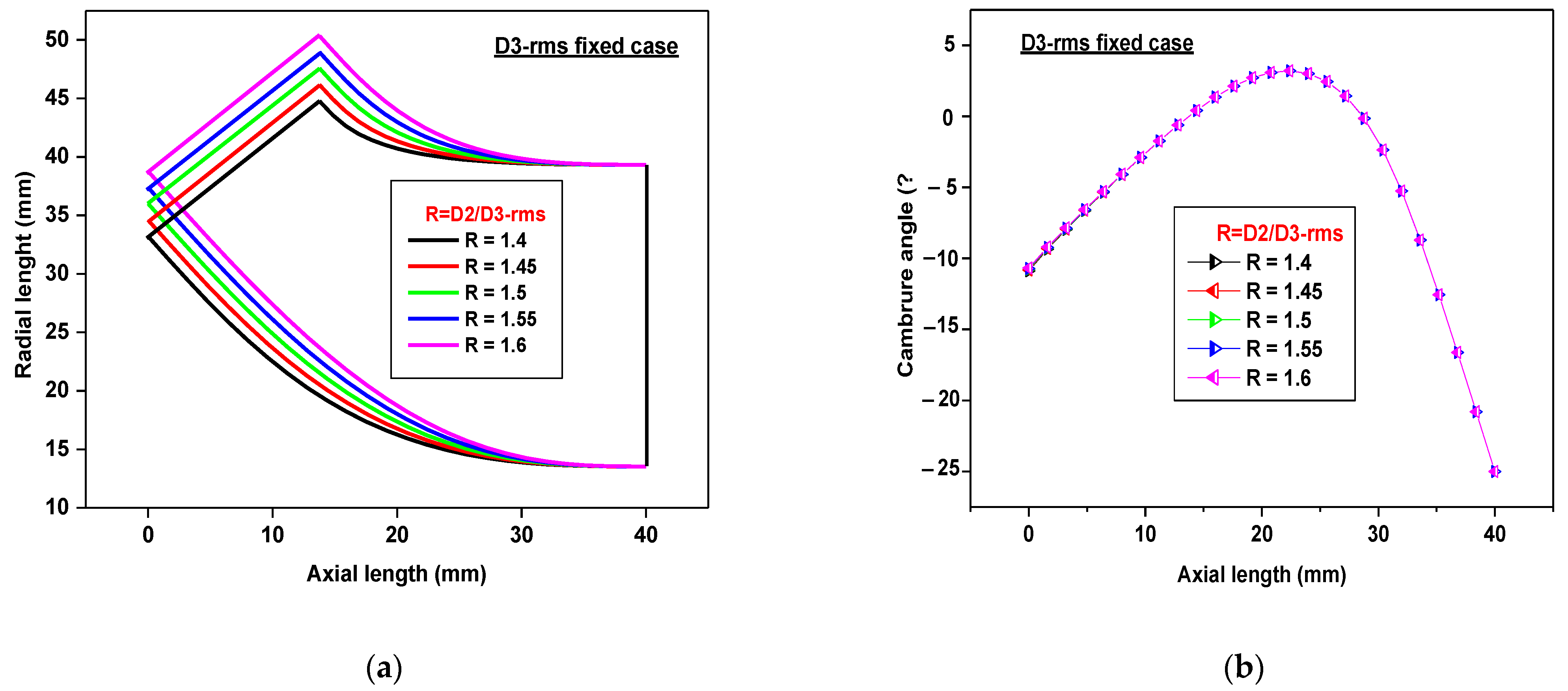
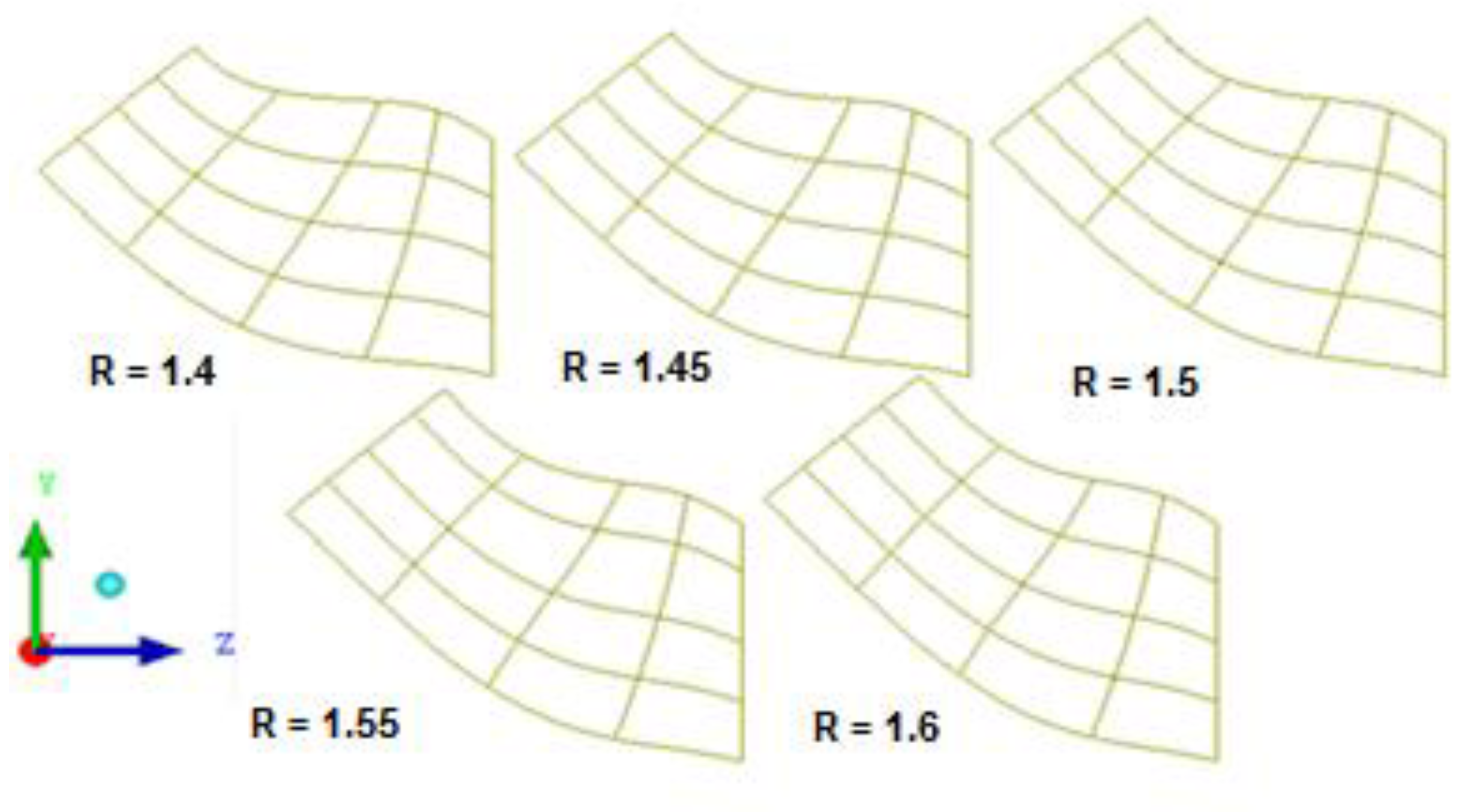
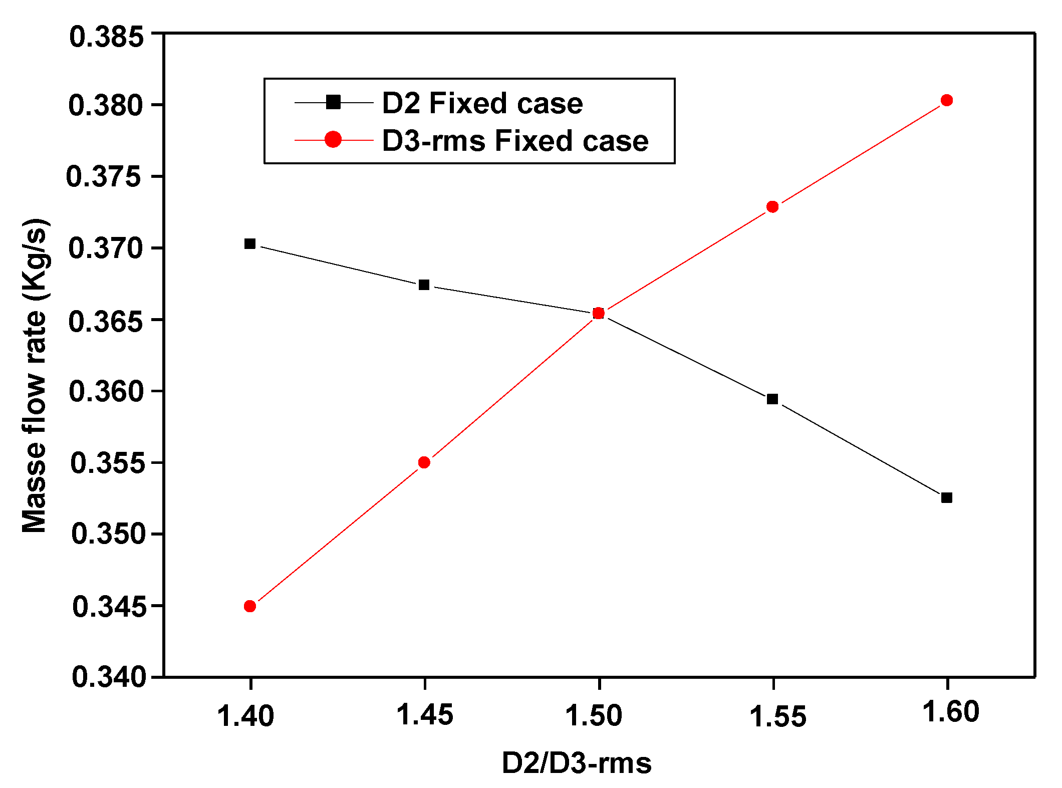
3. Results and Discussions

The three-dimensional shape of the blade and its area is influenced by the ratio between the average inlet diameter and the average exducer root diameter and, in general, this change is reflected—in turn—in the rotor performance. For comparison purposes, the numerical simulation results of the diameter ratio effect in the two cases at full rotation speed on the same schematic diagram were discussed: the first by fixing the average inlet diameter and the second by fixing the average exducer root diameter.
Figure 16 shows that the flow is inversely proportional to the ratio of the diameter in the case of a fixated average inlet diameter and is directly proportional in the case of a fixed average exducer root diameter. This can be explained—in the first case—by the narrowness of the rotor outlet channel caused by the decrease in the effective hydraulic diameter at the outlet, which is a function of the casing and hub diameters at the rotor outlet. In the second case, this can be explained by the widening of the rotor, as the inlet channel depends on the increase in the effective hydraulic diameter at the inlet, which is a function of the casing and hub diameters at the rotor inlet. For the purpose of the cases discussed above, the effective hydraulic diameter is the ratio between the passage section and the perimeter affected by the flow.
Figure 17 shows that the output work increased as the ratio between the diameters increased in both cases, and by using Table 3, it could be justified as a result of increasing the contact surface area in the case of fixed average exducer root diameter. However, for the fixed average inlet diameter case, it was observed that the blade area decreased with the increase in the ratio of the diameters (Table 1 and Table 2) and in spite of that, the output work was escalating. This can be explained by increasing the length of the blade streamwise, which is the actual contact area between the blade and the gas (Figure 12a). It was noticed that the output work for the fixed value of the average exducer root diameter case was higher than the output work obtained for the fixed value of the average inlet diameter case for all diameter ratios. Perhaps this is due to the new values of the inlet blade angle making it compatible with the gas flow.
Figure 18 illustrates the power that corresponded to the multiplication between output work and flow mass rate was directly proportional to the ratio of the diameter in the case of the fixed average exducer root diameter, due to the escalation of output work and mass flow rate together. As for the inlet mean diameter case, the power was escalating to a peak, which was proportional to the 1.55 of the diameter’s ratio value, and then it went down. It can be justified by the decline in the flow values and the increase in output work at the same time.
Figure 19 shows that the relative Mach number behavior for the fixed average inlet diameter case was similar to the behavior of a fluid flow moving across two successive channels.
The first one was a convergent-divergent channel, which led to the acceleration of the relative Mach number and then to its deceleration, since the flow regime was subsonic at the inlet of the rotor. It was observed that the default length of the (converging) first part of the convergent-divergent channel increased with the increase in the ratio of the diameter, while the default length of the second (diverging) part of the convergent-divergent channel increased with the decrease in the diameter ratio in the first part of the convergent-divergent channel; this can be explained by the boundary layer formation that did not change the actual, convergent, shape of the turbine channel, while its length was directly proportional to the diameter’s ratio. As for the second part of the channel (the divergent part), this can be justified by a thick boundary layer formation in this region, which changed the real shape of the rotor channel, making it divergent, and whose length is inversely proportional to the ratio of the diameters. It was observed that the relative Mach number at the rotor inlet increased with a decreasing ratio between the diameters, even though the rotor inlet area remains constant. This can be justified by the fact that the thickness of the boundary layer is greater in the case of a smaller diameter ratio.
The second one was a convergent channel, which led to the acceleration of the relative Mach number because the flow regime remained subsonic at the outlet of the first channel. It is noted that the length of this channel decreased with the increase in the diameter’s ratio, and the reason for this was the formation of the boundary layer without changing the actual, convergent, shape of the turbine channel, along with an inverse proportion for its length with the ratio of the diameter. It was observed that the relative Mach number at the outlet of the rotor increased with the increase in the ratio of the diameter, except for the case in which the ratio’s value was 1.45. This can be justified by the fact that the outlet area of the rotor decreased proportionally with the increase in the diameter’s ratio. However, the situation occurring in the case of the 1.45 value can be explained by the thicker boundary layer generated at this value.
The same observations were extracted from Figure 20. It was observed that the relative Mach number was more likely to increase for the fixed average inlet diameter case compared to the fixed average exducer root diameter case. This is because the default axial length of the second part of the convergent-divergent channel was shorter in the first case and longer in the second case.
Figure 21 illustrates that the total static isentropic efficiency was directly proportional to the diameter ratio for the two cases under investigation. It can be explained by the decrease in the blade friction losses for the fixed average inlet diameter case (Table 2) and the decrease in the incidence losses that were dominant for the average fixed mean root diameter case. It was remarked that the total static isentropic efficiency for the fixed value of the average exducer root diameter case was higher than the output work for the fixed value of the average inlet diameter case for all diameter ratios, so it can be argued that friction losses were evident.
The importance of the contour of static pressure on the extrados and the relative Mach number near the rotor for the two cases are presented in Figure 22 and Figure 23. Generally, at the intrados, the pressure gradient is almost positive in the radial direction while it is negative in the axial direction (Figure 22a and Figure 23b). This proves that the pressure is uniformly distributed in this part of the blade. Contrary to the inlet areas, the pressure variation on the extrados is disturbed, and this can be justified by the appearance of a “pocket” of recirculation within this zone. The low-pressure area can cause high stresses on the blade, and the high-velocity flow concentration can erode the surface of the blade. Therefore, the area of low pressure and high velocity should be avoided, or at least the pressure gradient should be minimized if these areas cannot be eliminated. Comparing all pressure and relative Mach number contours on the blade, designs with a 1.6 ratio for the discussed two cases were not a very good choice in terms of design vis a vis the blade lifetime.
The choice of the rotor material depends on the highest static temperature over the blades. A good distribution of the static temperature over the blade could result in a well-balanced thermal stress in the rotor. It may also indicate a lower temperature loss occurring near the blade. Figure 24 shows the static temperature contours on the exducers in the two cases. From the contours, one can see a drop in temperature from the inlet to the outlet, due to the acceleration of the flow through a converging passage. By comparing the contours of the two cases, it is obvious to notice that all blades have compatible thermal stress.

4. Conclusions

The change in the complex of physical, gas-dynamic parameters and the efficiency of a mixed turbine depends on the ratio between the average diameter of the rotor at the inlet and the average diameter of the inlet of the exducer. A mathematical model for controlling the three-dimensional geometric dimensions of the blade was used. It was described by a Bezier polynomial of the fourth degree, with the definition of the meridian plane and the Cumberline profile. An iterative calculation was used to compare the characteristics of a rotor with a given ratio of diameters. The inlet and outlet blade angles were recalculated to keep the blade profile unchanged.
It was found that—with a change in the exducer average root diameter and a fixed value of the average diameter of the rotor at the inlet—the output work and the total static isentropic efficiency were directly proportional to the ratio between the blade diameters. At the same time, the output work increased by 2.16%, along with a mass flow saving of 3.52%, which ultimately led to an increase in the isentropic efficiency by 2.15%. It should also be noted that the weight of the rotor was reduced by 31.98% while maintaining the size required to fit in the casing.
In the second scenario, with a change in the average diameter at the inlet and a fixed value of the exducer average root diameter, the work at the exit and the total static isentropic efficiency was also directly proportional to the diameter ratio, but higher than in the first case, since they reached values of 3.31% and 2.34%, respectively. However, this was accompanied by an increase in the mass flow rate by 4.07% and an increase in the dimensions of the rotor by 6.63%.
An analysis of the static temperature distribution, static pressure, and relative Mach number revealed dangerous low-pressure areas on the blade surface, accompanied by a high relative Mach number. The most rational choice would be to use the diameter ratio (R) in diapason from 1.5 to 1.55. The higher probability of blade surface erosion with a diameter ratio of 1.6 in both cases should be expected.
In general, a more accurate determination of the economic efficiency of a turbine in the stages of design and while running is a complex multi-parameter problem that requires an optimization solution, which the authors plan to approach in future studies.

Author Contributions

Conceptualization, M.A.C. and Y.B.; methodology, M.A.C.; software, M.A.C., S.D., M.E. and Y.B.; validation, S.D., J.M. and J.Z.; formal analysis, S.D. and B.A.A.; investigation, M.A.C. and Y.B.; resources, Y.B. and M.A.C.; data curation, J.M.; writing—original draft preparation, M.A.C. and Y.B.; writing—review and editing, S.D. and J.M.; visualization, M.A.C., Y.B. and B.A.A.; supervision, M.E. and J.Z; project administration, M.A.C., Y.B. and J.M.; funding acquisition, J.M. All authors have read and agreed to the published version of the manuscript.

Funding

The authors are grateful to FCT—Fundação para a Ciência e Tecnologia (Portugal)—who partially financially supported this work through the RD Units Project Scope: UIDP/04077/2020 and UIDB/04077/2020.

Institutional Review Board Statement

Not applicable.

Informed Consent Statement

Not applicable.

Data Availability Statement

Not applicable.

Acknowledgments

The general approach has been partially developed within the research project “Development of a methodology for optimal design and manufacture highly efficient, highly reliable turbomachines, taking into account various operating modes” (State reg. No. 0121U107511).

Conflicts of Interest

The authors declare no conflict of interest.

Abbreviations

b 2 Height at the inlet of the rotor
D2Means diameter at rotor inlet
D 3 r m s Exducer mean root diameter
D3HExducer hub diameter
D3SExducer shroud diameter
iIteration
rRadial polar variable
RRatio
r 0 h The radius at hub inlet rotor
R c The calcul ratio
X1Length of the rotor
x 0 h The axial distance for the initial hub
x r e f Reference axial distance of the blade
β 2 b Inlet balde angle
θ Camber angle
θ r e f Reference camber angle
δ2Cone angle at the inlet blade

References

  1. Sawada, T.; Nishi, A. Investigation of Radial Inflow Turbine: 2nd Report A Method of Performance Estimation for Variable Geometry Radial Inflow Turbine. Trans. Jpn. Soc. Mech. Eng. 1969, 35, 2401–2411. [Google Scholar] [CrossRef] [Green Version]
  2. Kofskey, M.G.; Haas, J.E. Effect of Reducing Rotor Blade Inlet Diameter on the Performance of a 11.66-Centimeter Radial-Inflow Turbine; Work of the US Gov. Public Use Permitted; NASA: Washington, DC, USA, 1973.
  3. Baines, N.C. Flow development in radial turbine rotors. In Proceedings of the 1996 International Gas Turbine and Aeroengine Congress & Exhibition, Birmingham, UK, 10–13 June 1996. [Google Scholar] [CrossRef] [Green Version]
  4. Roelke, R.J. Radial Turbine Cooling; Work of the US Gov. Public Use Permitted; NASA: Washington, DC, USA, 1992.
  5. Jones, A.C. Design and test of a small, high pressure ratio radial turbine. J. Turbomach. 1996, 118, 362–370. [Google Scholar] [CrossRef]
  6. Takamura, T.; Nishiguchi, F. Influence of blade aerodynamic loading on efficiency of radial-inflow turbines. In Proceedings of the ASME 1992 International Gas Turbine and Aeroengine Congress and Exposition, GT 1992, Cologne, Germany, 1–4 June 1992. [Google Scholar] [CrossRef] [Green Version]
  7. Chen, H.; Abidat, M.; Baines, N.C.; Firth, M.R. The Effects of Blade Loading in Radial and Mixed Flow Turbines. In Proceedings of the ASME 1992 International Gas Turbine and Aeroengine Congress and Exposition, GT 1992, Cologne, Germany, 1–4 June 1992. [Google Scholar] [CrossRef] [Green Version]
  8. Rodgers, C. Turbochargers to Small Gas Turbines? In Proceedings of the ASME 1997 International Gas Turbine and Aeroengine Congress and Exhibition, Orlando, FL, USA, 2–5 June 1997. [CrossRef] [Green Version]
  9. Wallace, F.J.; Baines, N.C.; Whitfield, A. A Unified Approach to the One-Dimensional Analysis and Design of Radial and Mixed Flow Turbines. In Proceedings of the ASME 1976 International Gas Turbine and Fluids Engineering Conference, New Orleans, LA, USA, 21–25 May 1976. [Google Scholar] [CrossRef] [Green Version]
  10. Ventura, C.A.M.; Jacobs, P.A.; Rowlands, A.S.; Petrie-Repar, P.; Sauret, E. Preliminary design and performance estimation of radial inflow turbines: An automated approach. J. Fluids Eng. Trans. ASME 2012, 134, 031102. [Google Scholar] [CrossRef]
  11. Zeng, F.; Zhang, W.; Wang, Y.; Cao, X.; Zou, Z. Effects of Squealer Geometry of Turbine Blade Tip on the Tip-Leakage Flow and Loss. J. Therm. Sci. 2021, 30, 1376–1387. [Google Scholar] [CrossRef]
  12. Pesiridis, A.; Martinez-Botas, R.F. Experimental evaluation of active flow control mixed-flow turbine for automotive turbocharger application. J. Turbomach. 2007, 129, 44–52. [Google Scholar] [CrossRef]
  13. Copeland, C.D.; Newton, P.; Martinez-Botas, R.F.; Seiler, M. A comparison of timescales within a pulsed flow turbocharger turbine. In Proceedings of the Institution of Mechanical Engineers—10th International Conference on Turbochargers and Turbocharging 2012, Savoy Place, London, UK, 12–16 May 2012; pp. 389–404. [Google Scholar] [CrossRef]
  14. Hagen, B.A.L.; Agromayor, R.; Nekså, P. Equation-oriented methods for design optimization and performance analysis of radial inflow turbines. Energy 2021, 237, 121596. [Google Scholar] [CrossRef]
  15. Dadone, A.; Pandolfi, M. A method for evaluating the off-design performance of a radial inflow turbine and comparison with experiments. Int. J. Mech. Sci. 1969, 11, 241–252. [Google Scholar] [CrossRef]
  16. Wasserbauer, C.A.; Glassman, A.J. FORTRAN Program for Predicting Off-Design Performance of Radial-Inflow Turbines; Work of the US Gov. Public Use Permitted; NASA: Washington, DC, USA, 1975.
  17. Rodgers, C. Advanced Radial Inflow Turbine Rotor Program:Design and Dynamic Testing; NASA-CR-135080, SOLAR-ER-2519; NASA: Washington, DC, USA, 1976.
  18. Lauriau, P.-T.; Binder, N.; Cros, S.; Roumeas, M.; Carbonneau, X. Preliminary design considerations for variable geometry radial turbines with multi-points specifications. Int. J. Turbomach. Propuls. Power 2018, 3, ijtpp3040022. [Google Scholar] [CrossRef] [Green Version]
  19. Alawadhi, K.; Alhouli, Y.; Ashour, A.; Alfalah, A. Design and optimization of a radial turbine to be used in a rankine cycle operating with an OTEC system. J. Mar. Sci. Eng. 2020, 8, 855. [Google Scholar] [CrossRef]
  20. Zahed, A.H.; Bayomi, N.N. Radial turbine design process. Isesco J. Sci. Technol. 2015, 11, 9–22. [Google Scholar]
  21. Rodgers, C. Radial turbines—Blade number and reaction effects. In Proceedings of the ASME Turbo Expo 2000: Power for Land, Sea, and Air, Munich, Germany, 8–11 May 2000. [Google Scholar] [CrossRef]
  22. Doran, W.J.; Spence, S.W.T.; Artt, D.W. Experimental performance evaluation of a 99.0 mm radial inflow nozzled turbine at larger stator-rotor throat area ratios. Proc. Inst. Mech. Eng. Part A J. Power Energy 1999, 213, 205–218. [Google Scholar] [CrossRef]
  23. Gao, Y.; Petrie-Repar, P. Validation of meanline performance prediction method for radial and mixed flow turbine. In Proceedings of the Institution of Mechanical Engineers—13th International Conference on Turbochargers and Turbocharging 2018, London, UK, 16–17 May 2018; pp. 357–372. [Google Scholar]
  24. Palfreyman, D.; Martinez-Botas, R.F. Numerical Study of the Internal Flow Field Characteristics in Mixed Flow Turbines. In Proceedings of the Turbo Expo 2002: Power for Land, Sea, and Air, Amsterdam, The Netherlands, June 3–6 2002; Volume 5, pp. 455–472. [Google Scholar] [CrossRef]
  25. Chou, C.; Gibbs, C.A. The Design and Testing of a Mixed-flow Turbine for Turbochargers. SAE Tech. Pap. Ser. 1989, 890644. [Google Scholar] [CrossRef]
  26. Minegishi, H.; Matsushita, H.; Sakakida, M.; Koike, T. Development of a Small Mixed-Flow Turbine for Automotive Turbochargers. Volume 2: Aircraft Engine; Marine; Microturbines and Small Turbomachinery. In Proceedings of the International Gas Turbine and Aeroengine Congress and Exposition, Houston, TX, USA, 5–8 June 1995. [Google Scholar] [CrossRef]
  27. Wallace, F.J.; Pasha, S.G.A. Design construction and testing of a mixed flow gas turbine. In Proceedings of the Second International JSME Symposium on Fluid Machinery and Fluids, Tokyo, Japan, 4–9 September 1972; pp. 213–214. [Google Scholar]
  28. Rajoo, S.; Martinez-Botas, R. Experimental study on the performance of a variable geometry mixed flow turbine for automotive turbocharger. In Proceedings of the 8th International Conference on Turbochargers and Turbocharging, London, UK, 17–18 May 2006; pp. 183–192. [Google Scholar] [CrossRef]
  29. Pesiridis, A.; Martinez-Botas, R.F. Experimental evaluation of active flow control mixed-flow turbine for automotive turbocharger application. In Proceedings of the ASME Turbo Expo 2005—Gas Turbie Technology: Focus for the Future, Reno, NV, USA, 6–9 June 2005; Volume 6, pp. 881–895. [Google Scholar] [CrossRef]
  30. Pesiridis, A.; Martinez-Botas, R. Active control turbocharger for auto-motive application an experimental evaluation. In Proceedings of the IMechE International Conference on Turbochargers and Turbocharging, London, UK, 17–18 May 2006; pp. 223–232. [Google Scholar]
  31. Pesiridis, A. Turbocharger Turbine Unsteady Aerodynamics with Active Control. Ph.D. Thesis, Imperial College London, London, UK, 2007. [Google Scholar]
  32. Lee, S.P.; Jupp, M.L.; Nickson, A.K.; Allport, J.M. Analysis of a tilted turbine housing volute design under pulsating inlet conditions. In Proceedings of the ASME Turbo Expo 2017, Charlotte, NC, USA, 26–30 June 2017. [Google Scholar] [CrossRef]
  33. Ketata, A.; Driss, Z. Numerical Study of a Vanned Mixed Flow Turbine Operating in Various Steady Flow Conditions. Int. J. Mech. Appl. 2017, 7, 24–30. [Google Scholar] [CrossRef]
  34. Ali, L.S.; Mohammed, H.; Kamel, H.M. The number of blade effects on the performance of a mixed turbine rotor. Eng. Rev. 2017, 37, 349–360. [Google Scholar]
  35. Meghnine, M.A.; Hamidou, M.K.; Hamel, M. Influence of the volute cross-sectional shape on mixed inflow turbine performances. Adv. Mech. Eng. 2017, 9, 1–15. [Google Scholar] [CrossRef] [Green Version]
  36. Hamel, M.; Bencherif, M.M.; Hamidou, M.K. Investigation of a twin entry mixed flow turbine volute, benefits with regard to the eco-system. Mater. Phys. Mech. 2017, 32, 31–42. [Google Scholar]
  37. Morrison, R.; Spence, S.; Kim, S.; Filsinger, D.; Leonard, T. Investigation of the effects of flow conditions at rotor inlet on mixed flow turbine performance for automotive applications. In Proceedings of the International Turbocharging Seminar 2016, Tianjin, China, 22–23 September 2016. [Google Scholar]
  38. Padzillah, M.H.; Rajoo, S.; Martinez-Botas, R.F. Experimental and numerical investigation on flow angle characteristics of an automotive mixed flow turbocharger turbine. J. Teknol. 2015, 77, 7–12. [Google Scholar] [CrossRef] [Green Version]
  39. Udayakumar, R.; Pipada, Y.V. Impact of mixed flow turbines on the efficiency of automotive turbocharger applications. Int. J. Mech. Eng. Robot. Res. 2020, 9, 791–796. [Google Scholar] [CrossRef]
  40. Karamanis, N.; Martinez-Botas, R.F. Mixed-flow turbines for automotive turbochargers: Steady and unsteady performance. Int. J. Engine Res. 2002, 3, 127–138. [Google Scholar] [CrossRef]
  41. Zhang, J.; Zangeneh, M. Multidisciplinary and multi-point optimisation of radial and mixed-inflow turbines for turbochargers using 3D inverse design method. In Proceedings of the 14th International Conference on Turbochargers and Turbocharging—Proceedings of the International Conference on Turbochargers and Turbocharging 2021, London, UK, 11-12 May 2020; pp. 263–277. [Google Scholar]
  42. Leonard, T.; Spence, S.; Filsinger, D.; Starke, A. Design and performance analysis of mixed flow turbine rotors with extended blade chord. J. Turbomach. 2020, 142, 121003. [Google Scholar] [CrossRef]
  43. Chelabi, M.A.; Hamidou, M.K.; Hamel, M. Effects of cone angle and inlet blade angle on mixed inflow turbine performances. Period. Polytech. Mech. Eng. 2017, 61, 225–233. [Google Scholar] [CrossRef]
  44. Chelabi, M.A.; Saga, M.; Kuric, I.; Basova, Y.; Dobrotvorskiy, S.; Ivanov, V.; Pavlenko, I. Effects of deviation blade angle on mixed inflow turbine performances. Appl. Sci. 2022, 12, 3781. [Google Scholar] [CrossRef]
  45. Chelabi, M.A.; Basova, Y.; Hamidou, M.K.; Dobrotvorskiy, S. Analysis of the three-dimensional accelerating flow in a mixed turbine rotor. J. Eng. Sci. 2021, 8, D1–D7. [Google Scholar] [CrossRef]
  46. Kononenko, S.; Dobrotvorskiy, S.; Basova, Y.; Gasanov, M.; Dobrovolska, L. Deflections and frequency analysis in the milling of thin-walled parts with variable low stiffness. Acta Polytech. 2019, 59, 283–291. [Google Scholar] [CrossRef] [Green Version]
  47. Dobrotvorskiy, S.; Kononenko, S.; Basova, Y.; Dobrovolska, L.; Edl, M. Development of Optimum Thin-Walled Parts Milling Parameters Calculation Technique. In Proceedings of the 4th International Conference on Design, Simulation, Manufacturing: The Innovation Exchange, DSMIE 2021, Lviv, Ukraine, 8–11 June 2021; Volume 2021, pp. 343–352. [Google Scholar] [CrossRef]
Figure 1. The mixed turbine rotor dimension’s view: (a) Intel view; (b) Outlet view; (c) Rotor length view; (d) Rotor in 3D view.
Applsci 12 12165 g001
Figure 2. The camberline blade view.
Applsci 12 12165 g002
Figure 3. The different geometrical zones.
Applsci 12 12165 g003
Figure 4. Effect of element number on static pressure around the blade for an average radius.
Applsci 12 12165 g004
Figure 5. Effect of the number of elements on the result of the study: (a) torque, (b) mass flow rate, (c) efficiency.
Applsci 12 12165 g005
Figure 6. Change in pressure distribution along the turbine canal length.
Applsci 12 12165 g006
Figure 7. Iterative calculation of the meridian plane based on the D 3 r m s verification.
Applsci 12 12165 g007
Figure 8. The inlet mean diameter and exducer mean root diameter presentation.
Applsci 12 12165 g008
Figure 9. The outlet blade angle presentation.
Applsci 12 12165 g009
Figure 10. The new meridian plane geometries: (a) with the same camberline shape; (b) for a fixed value of average inlet diameter.
Applsci 12 12165 g010
Figure 11. The different blade shapes view for a fixed value of average inlet diameter.
Applsci 12 12165 g011
Figure 12. Calculation of the meridian plane based on the input value of D 3 r m s .
Applsci 12 12165 g012
Figure 13. The inlet blade angle presentation.
Applsci 12 12165 g013
Figure 14. The new meridian planes geometries: (a) with the same camberline shape; (b) fixed value of average exducer root diameter.
Applsci 12 12165 g014
Figure 15. The different blade shapes views for a fixed value of average exducer root diameter.
Applsci 12 12165 g015
Figure 16. Mass flow rate for a different ratio between the average inlet diameter and average exducer root diameter.
Applsci 12 12165 g016
Figure 17. Output work for different ratios between the average inlet diameter and average exducer root diameter.
Applsci 12 12165 g017
Figure 18. Power for different ratios between the average inlet diameter and average exducer root diameter ratio.
Applsci 12 12165 g018
Figure 19. Relative Mach number for a fixed average inlet diameter case.
Applsci 12 12165 g019
Figure 20. Relative Mach number for the fixed average exducer root diameter case.
Applsci 12 12165 g020
Figure 21. Total to static efficiency for different ratios between the average inlet diameter and the average exducer root diameter.
Applsci 12 12165 g021
Figure 22. Static pressure contours on extrados: (a) With the relative Mach number contours near the extrados; (b) For a fixed value of the average inlet diameter.
Applsci 12 12165 g022
Figure 23. Static pressure contours on extrados: (a) With the relative Mach number contours near the extrados; (b) For a fixed value of the average exducer root diameter.
Applsci 12 12165 g023
Figure 24. Static temperature contours on extrados: (a) For a fixed value of the average inlet diameter; (b) For a fixed value of the average exducer root diameter.
Applsci 12 12165 g024
Table 1. The geometrical parameter values (in mm).
b2D2R0hR0sX1b3D3hD3-rmsD3s δ 2 ( ° ) θ 3 ( ° ) β 2 b ( ° ) β 3 ( ° )
17.9983.583647.574025.7927.0755.778.6540−2520−52
Table 2. The meridian plan geometrical parameter values for a fixed value of average inlet diameter (in mm).
b2D2R0hR0s β 2 b   ( ° ) b3D3hD3-rmsD3s β 3   ( ° ) A (mm2) R
17.9983.5836.00847.5720.0025.7938.797059.790.3770−53.9010461.4
17.9983.5836.00847.5720.0025.7932.915757.684.4957−52.9410291.45
17.9983.5836.00847.5720.0025.7927.070055.778.6500−52.0010131.5
17.9983.5836.00847.5720.0025.7921.120053.972.7000−51.089981.55
17.9983.5836.00847.5720.0025.7914.981052.266.5610−50.189861.6
Table 3. The meridian planes geometrical parameter values for a fixed value of average exducer root diameter (mm).
b2D2R0hR0s β 2 b   ( ° ) b3D3hD3-rmsD3s β 3   ( ° ) A (mm2) R
17.9977.9833.21144.76918.9125.7927.070055.790.3770−52.0010011.4
17.9980.7734.60346.16219.4525.7927.070055.784.4957−52.0010071.45
17.9983.5836.00847.5720.0025.7927.070055.778.6500−52.0010131.5
17.9986.3437.38848.94720.5325.7927.070055.772.7000−52.0010191.55
17.9989.1238.78150.33921.0725.7927.070055.766.5610−52.0010251.6
Publisher’s Note: MDPI stays neutral with regard to jurisdictional claims in published maps and institutional affiliations.

