Article

Mechanical Properties and Engineering Applications of Special Soils—Dynamic Shear Modulus and Damping of MICP-Treated Calcareous Sand at Low Strains

1
Research Center of Urban Underground Space, Nanjing Tech University, Nanjing 211816, China
2
Key Laboratory of Ministry of Education for Geomechanics and Embankment Engineering, College of Civil and Transportation Engineering, Hohai University, Nanjing 210098, China
3
Key Laboratory of New Technology for Construction of Cities in Mountain Area, College of Civil Engineering, Chongqing University, Chongqing 400045, China
*
Author to whom correspondence should be addressed.
Appl. Sci. 2022, 12(23), 12175; https://doi.org/10.3390/app122312175
Submission received: 3 November 2022 / Revised: 20 November 2022 / Accepted: 23 November 2022 / Published: 28 November 2022
(This article belongs to the Special Issue Mechanical Properties and Engineering Applications of Special Soils)

Abstract

:
Calcareous sand deposits are widespread along the shoreline in tropical and subtropical regions. Microbially induced calcite precipitation (MICP) treatment is a new method for improving the soil’s stiffness and strength. The small-strain shear modulus and damping ratio of MICP-treated calcareous sand, two critical parameters for predicting the dynamic behavior of soil, are little known. This study conducts a series of resonant column tests to investigate the dynamic characteristics of MICP-treated calcareous sand, emphasizing the influence of treatment duration and confining stress on the stiffness and damping characteristics. It analyzes the relationship between the initial dynamic shear modulus and unconfined compressive strength. In addition, empirical relationships between the reference shear strain and treatment duration or confining stress are provided. The results show that the normalized shear modulus G/G0 of MICP-cemented calcareous sand has a higher strain sensitivity than that of untreated sand, and the Hardin–Drnevich model can describe its attenuation pattern. The effective confining stress σc affects the degradation characteristics of the dynamic shear modulus of MICP-treated calcareous sand with a low cementation level; however, its impact decreases as the treatment duration increases. There is a linear relationship between the reference shear strain and confining stress. While the relationship between the reference shear stain and treatment duration is a power law.

1. Introduction

Calcareous sand is widespread along the coastline of the South China Sea, the Red Sea, Australia, the Gulf of Mexico, and other tropical or subtropical regions [1], making it an essential component of construction materials in coastal structures. Usually, calcareous sand consists of the reworked shell fragments and skeletal debris of marine organisms [2,3]. Calcareous sand has unique features, such as irregularly shaped particles, a porous interior, a polygonal angle, and crushable grain [4]. As a result, the mechanical behavior of calcareous sand can be considerably different from siliceous sands due to their diverse mineral resources and particle characteristics [5,6].
Several conventional geotechnical applications, including grouting, densification and deep mixing, have been explored to enhance siliceous sand’s bearing capacity and liquefaction resistance [7]. The development of new technologies and materials, such as microbially induced calcite precipitation treatment [8,9,10] and nano-modification [11,12,13], have attracted great attention due to their low cost, low pollution, and harmless impact on the environment. However, when the MICP is performed in clay soil, the ground improvement cost is increased due to clay soil’s low permeability [14]. The production of carbonate precipitation is affected by environmental factors, such as calcium concentration, bacterial concentration, pH, and temperature [15]. MICP treatment is suitable for treating artificial calcareous sand islands far from the inland and with a poor construction environment. Microbially induced calcite precipitation (MICP) is a modern technology that utilizes biological metabolic processes to improve soil properties [16,17,18]. The fundamental chemical reactions governing the MICP process can be defined as follows [8,19]:
CO(NH2)2 + 2H2O → 2NH4+ + CO32−
Ca2+ + CO32− → CaCO3
Soil improvement methods include environmental friendliness, a far transmission distance, low disturbance, and controllability of the process [10]. MICP has been applied to solve practical engineering problems, such as increasing soil strength and stiffness [19,20], reducing soil permeability [21], repairing cracks in the structure [22], and controlling erosion [23]. MICP treatment has recently been demonstrated to improve calcareous sand’s static strength and liquefaction resistance due to the calcite crystal precipitation between the sand particles, which strengthens the soil structure [1,16,24]. The composition, shape, and pore structure of calcareous sand particles are more suitable for calcium carbonate precipitation than siliceous sand [1,25,26].
However, studies on the dynamic properties of MICP-treated calcareous sand, such as the small-strain dynamic shear modulus and damping ratio, are rare. The dynamic shear modulus and damping ratio are essential for analyzing soil’s dynamic response during dynamic loading conditions, such as earthquakes, traffic, and wave loads [27]. Over the past few decades, the dynamic properties of naturally occurring calcareous sand have been extensively investigated in the laboratory [28,29]. For example, the small-strain shear modulus and damping ratio of calcareous sand under an isotropic or anisotropic stress consolidated state have been studied [30,31,32,33]. The effects of confining stress, pore ratio, relative density, grading and particle size, and particle breakage on the dynamic properties have also been discussed [5,29,30,31,32,33,34,35]. Morsy et al. [34] discovered that the effect of the void ratio on shear modulus is more pronounced at low void ratios, and the maximum shear modulus increases as the void ratio decreases. Javdanian and Jafarian [5] conducted resonant column and cyclic triaxial tests on two marine calcareous sand samples and reported that as the effective confining pressure grows, the shear stiffness ratio rises while the damping ratio decreases. Hassanlourad et al. [35] examined the shear behavior of calcareous sand using drained and undrained triaxial tests, revealing the effect of particle breakage on specimen response. Khalil et al. [36] performed a series of bender element and cyclic triaxial tests to study the low-strain and high-strain characteristics of calcareous sand and terrigenous sand.
Although numerous researchers have studied the dynamic shear modulus and damping ratio at low strains on natural and cement-stabilized soil [30,34,36,37,38,39,40,41], considerably less information is known about the dynamic response of marine soil, such as calcareous sand at different MICP-treatment levels. Understanding how the shear modulus and damping ratio of MICP-treated calcareous sand varies with shear strain and other factors for engineering applications is necessary. Many studies have shown that the dynamic properties of cemented soils are affected by the cementation level [20,42] and confining stress [43,44,45,46,47]. Accordingly, the main objective of this investigation is to evaluate the dynamic behavior of MICP-treatment calcareous sands at a low strain amplitude, focusing on the effect of confining stress and treatment time on the precipitated calcite contents. A series of resonant column tests are conducted to determine calcareous sand’s dynamic shear modulus and damping ratio at a low MICP-treated level. Initially, this paper describes the test materials and implementation methods. The effect of MICP treatment on the dynamic response of saturated calcareous sand at a low shear strain, including the responses of the dynamic shear modulus, degradation characteristics of a normalized dynamic shear modulus, and the damping ratio, is then discussed. In addition, the correlations of the initial dynamic shear modulus with an unconfined compression strength, confining stress, and treatment time are addressed. Finally, the relationship between the reference shear strain and the treatment duration or confining stress are proposed. The study’s results provide a quantification of dynamic parameters of MICP-treated calcareous sand and relevant support for the development of constitutive models.

2. Materials and Methods

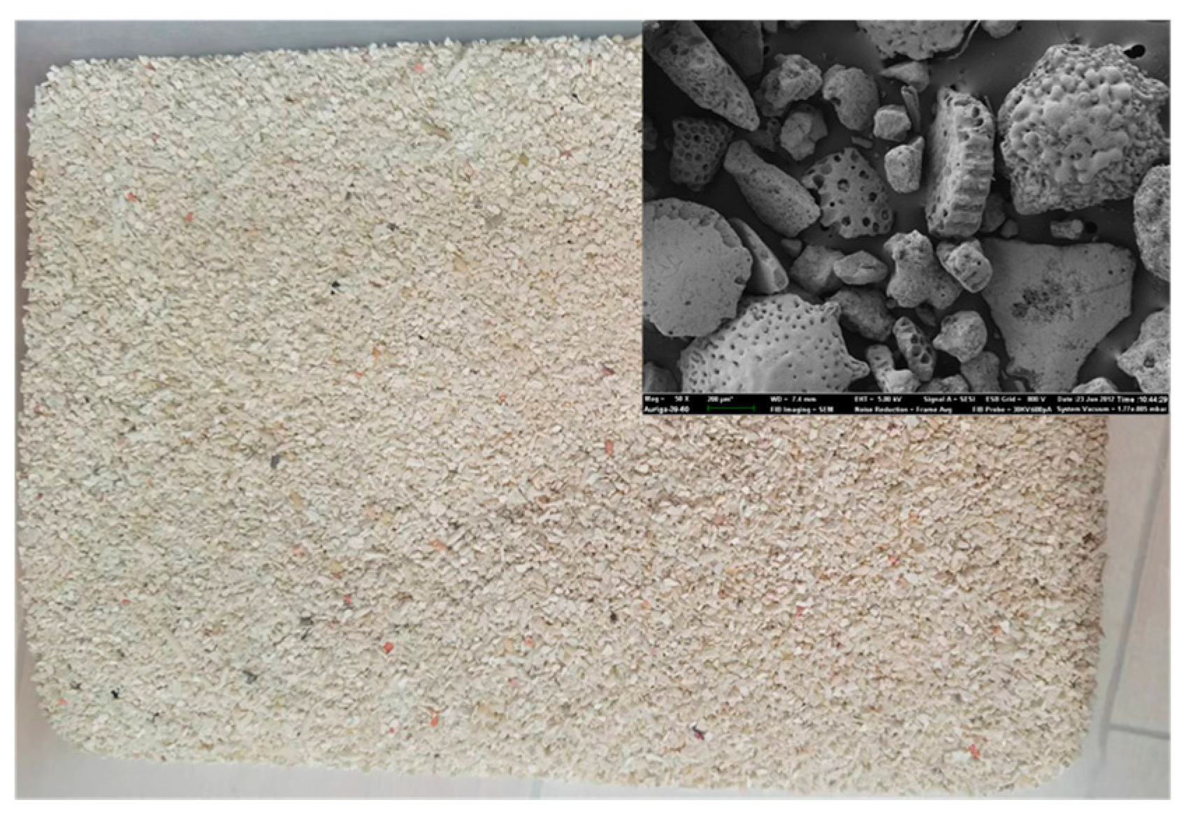
2.1. Material Properties

The calcareous sand used in the current study was collected from an island in the South China Sea, and its particle size distribution curve is depicted in Figure 1. The calcium carbonate content of this sand exceeds 90.25%, as determined by the chemical componential analysis; its microscope (SEM) images are shown in Figure 2, and a summary of the sand’s parameters tested with the ASTM standard is listed in Table 1. Calcareous sands have a coefficient of uniformity of Cu equal to 3.55 and a coefficient of curvature of Cc equal to 0.97, and they are classified as poorly graded sand based on the ASTM D 2487 standard testing procedures.

2.2. MICP Treatment Procedure

Sporosarcina pasteurii (American Type Culture Collection, ATCC11859) is an aerobic uratolytic bacterium that uses urea as a nutrient and produces CO32− as the critical part of CaCO3 precipitation. The bacterial fluid was cultured in a medium solution (with a ratio of 1:10), whose composition is presented in Table 2. The bacteria were enlarged in an incubator shaker at 30 °C at a speed of 210 rpm for approximately 24–32 h. The harvested bacteria’s optical density (OD600) was about 0.71, and the urease activity was approximately 1.1 mM urea hydrolyzed per min. The cementation solution (CS) used in the experiments was a mixture of 0.5 mol/L urea and 0.5 mol/L CaCl2. The volume of the cementation solution utilized for each sample in the tests was about seven times the sample pore volume, i.e., 720 mL.
The calcareous sand samples were prepared using a series of specially designed devices to achieve batches of intact samples, as illustrated in Figure 3. The specimen’s preparation device consisted of two semi-cylindrical PVC molds that could be quickly disassembled, two pieces of filter fabric to prevent the fine sand particles from being flushed out during the treatment process, a small aspirating hole on the mold to connect with the vacuum pump, and two PVC pedestals. The PVC split mold had an internal diameter and height of 5 cm and 10 cm, respectively. A thin rubber membrane was attached to the inner walls of the columniform mold. A vacuum pump was connected to the aspirating hole on the mold during the sample preparation process to draw a negative pressure between the rubber membrane and the inner wall of the mold without leaving any gaps to produce standard diameter samples.
Samples of 50 mm diameter and 100 mm high were prepared with dry tamping in the split mold. The sample preparation process was divided into several steps. First, to obtain a more uniform specimen, about 345 g of dry calcareous sand was spread into the thin rubber membrane in five layers. Each layer should be filled evenly, and the last layer’s surface should be as smooth as possible; because the calcareous sand grain shows crushability under a shocking load, a rubber hammer was used to slightly tamp the mold outside to achieve the designed height. The relative density of the reconstituted specimens was controlled at about 40%. Second, once the sand sample was produced, 110 mL of the bacterial liquid was injected into the sand specimen utilizing a peristaltic pump at a rate of 180 mL/h. The bacterial solution was inoculated in the soil pore space for at least 6 h to allow the bacteria to diffuse and adhere to the soil particles. Third, after the detention of the bacterial fluid, the cementation solution was pumped into the soil sample at a rate of 180 mL/h and was allowed to flow out freely by the pipe on the top cover. All specimens were flushed with distilled water equal to four times the volume of the voids at the end of the treatment to purge them of the bacterial solution and residual cementation solution and to saturate the sample.

2.3. Equipment and Testing Procedure

The experiments related to the MICP-treated calcareous sand were conducted using the resonant column apparatus TSH-100 developed by GCTS, as shown in Figure 4a. The shear modulus can be calculated by combining the frequency–response curve data, specimen size, and physical characteristics of the resonant column test apparatus. The configuration of the resonant column apparatus is bottom-fixed and top-free, and it can be modified according to the size of prepared soil specimens. The maximum pressure of the air-filled cell is 1 MPa, and there is an internal high-resolution LVDT for measuring the deformation of specimens. The specimen and vibration generator were enclosed together within the pressure chamber. The specimen’s resonant frequency was determined by changing the excitation frequency and force applied to the bottom of the specimens. The shear modulus G was calculated using the theory of elastic wave propagation as follows:
G = ρ V S 2
V S = 2 π f n l β
where VS is shear wave velocity, ρ is density, and fn is the natural frequency of the system. β is a function of the mass polar moment of inertia of both specimen I and the mass attached at the free end of the specimen I0, as determined by:
β tan ( β ) = I / I 0
In this study, the damping ratio is determined from the frequency–response curve, which can be calculated using:
D = ( f 2 f 1 2 f n ) × 100
where f1 and f2 are the frequencies at A = A max / 2 , in which A is the acceleration of resonant frequency, and Amax is the maximum acceleration.
The test procedure can be divided into four steps. First, the prepared sample was installed on the base, and the top of the sample was connected to a vibration generator. Second, the back-pressure saturated method was applied to ensure that the specimens were saturated and the back pressure was 400 kPa. In this study, a B-value of more than 0.97 was reached for all the specimens. The effective confining stress was then increased to the target value and maintained. When the average strain rate of the sample was less than 1 × 10⁻³%/min, the consolidation step was completed. Finally, the resonant frequency was determined by changing the excitation frequency and force applied to the bottom of the specimens, and the values of the dynamic shear strain, shear wave velocity, and dynamic shear modulus were recorded.
A series of unconfined compressive tests were performed to analyze the relationship between the static strength and the dynamic properties of the MICP-treated calcareous sand. The unconfined compressive strength of the MICP-treated samples was measured using a YSH-2 type of unconfined compression apparatus (Figure 4b). The upper and lower surfaces of the samples were leveled and placed on the unconfined compressive apparatus. The unconfined compression strength of the soil samples was measured with a loading speed of 1 mm/min.
The samples were oven-dried at a temperature of 60° for a duration of 72 h after unconfined compressive and resonant column tests to determine the content of CaCO3 that can be computed utilizing the following formula:
C C ( % ) = m 0 m m = Δ m m × 100
where CC is the content of CaCO3 in the specimen, m and m0 are the oven-dried mass of the dry specimen before and after MICP treatment, and Δm is the mass of CaCO3.

2.4. Experimental Program

This study conducted 18 groups of resonance column tests, including 15 groups of treated conditions and 3 groups of untreated conditions for comparison to the treated samples. The effects of treatment times (e.g., 6 h, 12 h, 18 h, 24 h, and 48 h) and the effective confining stress (e.g., 25 kPa, 50 kPa, and 100 kPa) were considered. In addition, five groups of unconfined compressive tests were carried out to establish the relationships between the initial dynamic shear modulus and the unconfined compressive strength. Table 3 displays the details of the samples and the contents of CaCO3.

3. Experimental Results

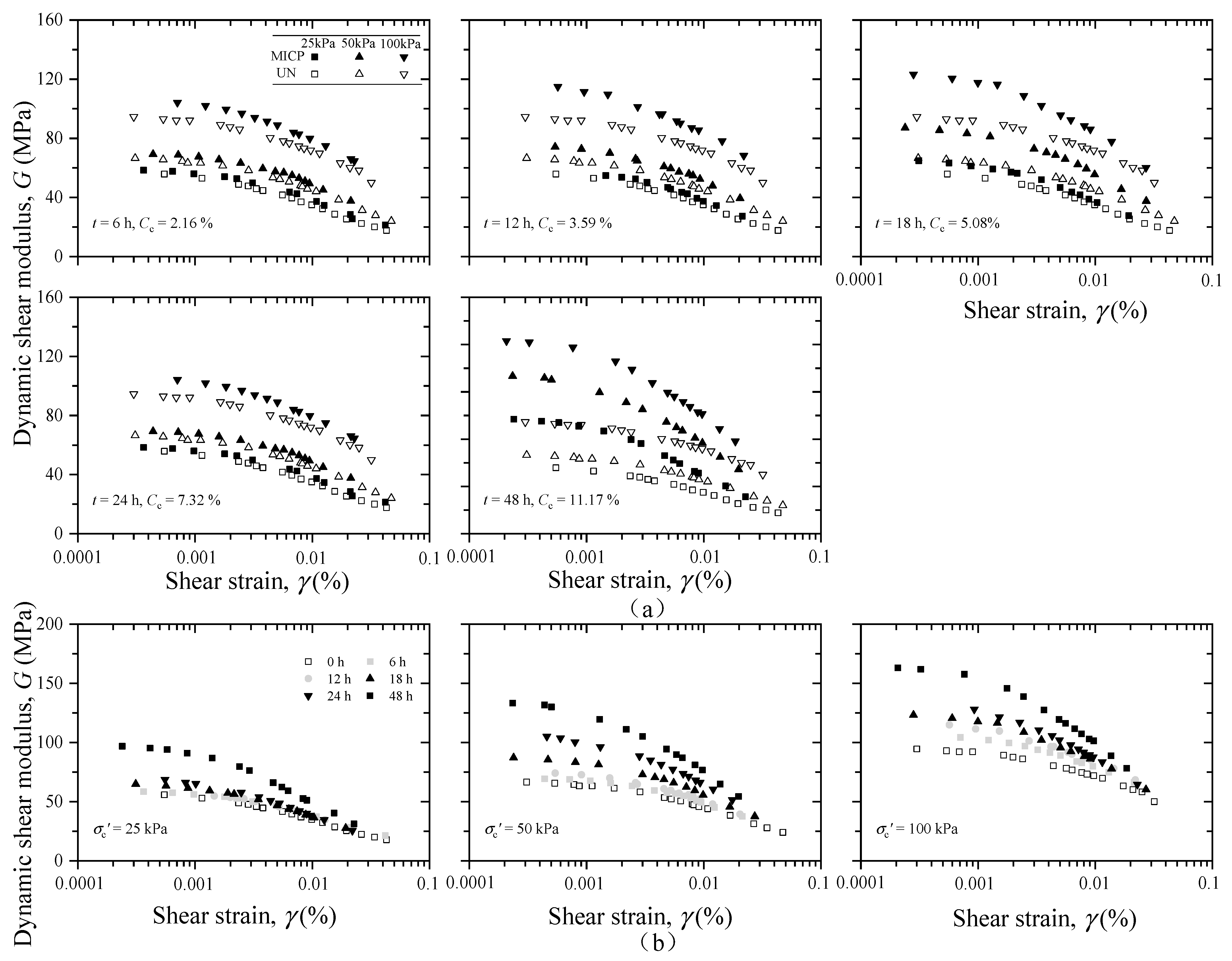
3.1. Dynamic Shear Modulus of MICP-Treated Calcareous Sands

Significant nonlinearity in soil stress–strain behavior is presented by two parameters of the shear modulus G and damping ratio D, which change with shear strain amplitude. Figure 5a illustrates the variation in G with the shear strain γ ranging from 10−4 to 4 × 10⁻²%. The shear modulus of the clean sands used in this investigation oscillated from 58 MPa to 20 MPa, 63 MPa to 23 MPa, and 95 MPa to 50 MPa at confining stress of 25 kPa, 50 kPa, and 100 kPa, respectively.
The dynamic shear modulus of the soil after treatment was not significantly increased at a low confining stress of 25 kPa when the treatment duration was less than 18 h. Because the amount of precipitated calcium carbonate in specimens with a low treated level is limited, and the stiffness of these cementations is low, a higher CaCO3 content is required for the loose and porous calcareous sands to form an effective bonding network. The treated sands have a higher shear modulus than the untreated sands at a small shear strain under the same loading conditions.
As the shear strain increases, the shear modulus of the MICP-treated sand gradually decreases and eventually approaches that of the untreated calcareous sand at approximately 0.03% shear strain. This observation indicates that when the shear strain exceeds 0.03%, the beneficial effect of calcite bonding between sand particles induced by MICP treatment disappears. Simatupang et al. [43] discovered comparable outcomes in their study of cemented sand. Under conditions of lower confining stress and a shorter treatment duration, the shear strain level at which the shear modulus of the MICP-treated sand decreases to the untreated value is generally lower.
Figure 5b depicts the dynamic shear modulus for various confining stresses. As the confining stress increases, the differences in the behavior of the shear modulus between treated and untreated sand become more pronounced. This is because the confining stress impacts the amount of effective contact between sand particles and/or calcium carbonate precipitation, thereby altering the dynamic shear modulus.

3.2. Initial Shear Modulus, G0

The initial shear modulus G0 is defined as the shear modulus at a small strain amplitude of 10−4%.
Figure 6a illustrates the effect of the confining stress on the initial shear modulus. The relationship between the initial shear modulus and the confining stress can be satisfactorily expressed by a power function of Equation (6) proposed by Hardin et al. [49]:
G 0 = α σ c β
where G0 is the initial shear modulus, α and β are the fitting parameters related to cement level, void ratio, and other factors, and σc is the confining stress. The R-square is greater than 0.96 in all cases. As the treatment time increased from 12 h to 48 h, α rose from 10.9 to 31.8, and β decreased from 0.51 to 0.36.
Figure 6b reveals the relationship between the initial shear modulus and the treatment duration. It indicates that the increasing treatment time contributed to the increase in G0, which can be attributed to the calcite cementation gradually precipitating with the increasing time. The shear modulus of the untreated sands at confining stress of 25 kPa, 50 kPa, and 100 kPa was 58 MPa, 68 MPa, and 95 MPa, respectively, and it was about 98 MPa, 133 MPa, and 164 MPa after being treated for 48 h.
When the MICP treatment time was less than 18 h, the difference between the dynamic shear modulus of the treated samples under a low confining stress of 25 kPa and untreated samples was not obvious. Under a confining stress of 100 kPa, the dynamic shear modulus of the treated samples was much higher than that of the untreated ones. This is because the calcareous sands used in the tests are loose and porous, making it challenging for calcium carbonate precipitated in the pores to form effective contacts in cases with short treatment time. The neighboring particles become clustered under a higher confining pressure, and the calcium carbonate particles precipitated in the pores, which do not contribute to the shear strength, have the potential to become effective contact points, thereby improving the initial dynamic shear modulus of the samples. Whiffin et al. [8] reported that a lower content of CaCO3 (CCaCO3 = 3.5%, which is consistent with the content of CaCO3 in the specimen treated for 12 h in this study) had no significant effect on the strength or stiffness properties of sand compared to untreated sand.
Researchers have stated that a reliable correlation can be established between the G0 and qucs for the cemented soil [49]. This study uses the average peak stress of two replicate specimens to represent the unconfined compressive strength. Figure 6c depicts the variation in G0 with qucs for bio-treated samples under different confining stresses. The G0 increases with the qucs, and the relationship between them can be defined by a power function presented by Consoli et al. [50]:
G 0 = m × q n ucs
where G0 is described in MPa, qucs is described in kPa, and constants m and n are the fitting parameters in the formula. The R-square exceeds 0.98 in all cases. The G0 of the treated sands rises nonlinearly with an increase in qucs, which is related to cementation between particles.

3.3. Degradation Characteristics of Normalized Dynamic Shear Modulus

The degradation characteristics of the strain-dependent normalized dynamic shear modulus (G/G0) are essential for predicting and characterizing the non-linear dynamic response of the soil. Figure 7 exhibits the normalized shear modulus degradation curves of the MICP-treated sands at low strains. As shown in Figure 7a, the degradation of G/G0 with γ in the higher confining stress is much slower for the same treatment time.
After MICP treatment, the G/G0 of the calcareous sandy sample decreases quickly with increasing strain due to the gradual deterioration of the bonding between sand particles. This indicates that the non-linear dynamic characteristic of MICP-treated calcareous sand is more pronounced, which has also been reported for other types of treated soil [5,35,38,40]. In addition, the strain sensitivity of samples with longer treatment times is more evidence indicating that the brittleness of MICP-treated calcareous sands grows during the treatment process.
The Hardin–Drnevich model [49] (Equation (8)) has been widely applied to describe the nonlinear relationship between the G/G0 and γ. It allows the normalized shear modulus reduction to be expressed by two parameters:
G / G 0 = 1 / ( 1 + ( γ / γ r ) ζ )
where γr is the reference shear strain, defined as the shear strain corresponding to G/G0 = 0.5, and ζ is the curvature coefficient.
All the experiments in this study reveal that the G/G0-lnγ curves of MICP-treated calcareous sands are well-fitted by the Hardin–Drnevich model, where R-square is greater than 0.98 in all cases. Table 4 lists the parameters of the Hardin–Drnevich model. The value of ζ ranges from 0.83 to 0.99 and decreases as the confining stress improves. Generally, the reference shear strain is less when the confining stress and treatment duration are reduced.
Figure 8 depicts a best-fit hyperbolic curve for all the data points (G/G0-lnγ/γr) when the shear strain γ is divided by the reference shear strain γr. The fitting parameter ζ is 0.9. The R-square value of 0.99 indicates that the model can be utilized to describe the behavior of stiffness attenuation in both treated and untreated calcareous sand. Hence, only one parameter, γr, can adequately represent the degradation characteristics of the normalized dynamic shear modulus.

3.4. Correlation between γr and t, σc

In this study, the relationship between γr and the treatment time or confining stress waws examined. Figure 9a illustrates the correlation between the reference strain and the treatment time. The reference shear strain can be described as a power function of processing time:
γ r = 1 / ( a + b t c )
where t is the treatment time, and a, b, and c are the fitting parameters. The fitting parameters a and b decrease from 3503.8 to 2396.9 and 383.9 to 106.2, respectively, and c increases from 0.74 to 0.92 as the confining stress increases from 25 kPa to 100 kPa.
Figure 9b indicates the correlation between the reference shear strain and the confining stress. The γr increases as σc rises, and the difference in γr between various treatment times grows with the increase in σc. This also demonstrates that the confining stress still significantly influences the shear modulus attenuation curve of the sand sample with a lower cementation level. In addition, as shown in Figure 9b, the difference of γr under various confining stresses decreases gradually as the treatment time rises, indicating that the effect of σc on the attenuation of the shear modulus drops during the treatment process. The relationship between γr and σc is linear and can be described by Equation (10), and the fitting R-square for all cases is greater than 0.99:
γ r = δ σ c + ϕ
where δ and ϕ are the fitting parameters. Both δ and ϕ drop gradually as the treatment time increases, resulting in a decrease in the slope and intercept of γrσc.
It should be noted the empirical relationships presented in this study are only applicable to MICP-treated calcareous sand. The applicability of these empirical formulas to pure calcareous sand needs further study and verification.

3.5. Dynamic Shear Modulus of MICP-Treated Calcareous Sands

Figure 10 depicts the variation in the damping ratio with strain amplitude (D-logγ relationship). The confining stress significantly impacts the damping ratio in the treated sample, with a lower value at a higher confining stress due to an increase in interparticle contacts. Hence, less energy will be dissipated for the wave to propagate.
Figure 11 indicates that the damping ratio rises slightly when the shear strain amplitudes are less than 1 × 10⁻³% and increases significantly once the shear strain amplitude is greater than 1 × 10⁻³%. It should be noted that the damping ratio initially grows with the treatment time (6 h–24 h) and then decreases gradually after around 24 h. Similar outcomes have been discovered in the studies of treated soils by a few researchers [50,51,52,53,54]. Delfosse-Ribay et al. [55] evaluated the damping ratio and shear modulus of sand samples grouted with three different cementitious materials and found that the samples with a greater dynamic shear modulus also had higher damping ratios. Saxena et al. [45] investigated the dynamic moduli and damping ratios of cemented sands at low strains using resonant column test. They reported that the damping ratio of cemented sands with a low cementation level increases with cement content and reaches its maximum value at a cement content of about 5% to 8% (defined as threshold cement content), then decreases with further cement content. In this study, the threshold calcium carbonate content was around 7% after 24 h of treatment.

4. Discussion

The composition, shape, and pore structure of calcareous sand particles are more suitable for calcium carbonate precipitation than siliceous sand [1]. However, the crystals developed mainly on the surface of the sand particles to coat the particle surfaces (in grain coating) due to the porosity and irregularly shaped particles of calcareous sand, especially in the lightly treated specimen. Identical results were observed by Xiao [1] and van Paassen [28].
San Pablo [56] discovered that various grains of sand subjected to similar treatments showed varying degrees of Vs improvement despite similar calcite contents. Identical findings were reported by Cheng [57] and Chu [58]. In reality, three distinct spatial distributions of CaCO3 precipitate exist in silica sand during MICP: (a) contact cementing, (b) grain coating, and (c) matrix supporting [10,59]. The increase in the modulus and strength of the MICP-treated specimen is primarily contributed by the interparticle cementation (contact cementing). Accordingly, in this paper, although the calcium carbonate content ranged from 2% to 11%, the rise in qu and G0 was limited compared to that of silica sand, because most of the CaCO3 precipitated in calcareous sand samples was wrapped on the surface of the particles during MICP treatment.
The influence of σc was removed by normalizing the G0, as shown in Figure 12. The normalized G0 rose linearly with the increase in CC. In future experiments, it would be beneficial to better understand the relationship between strength/stiffness and calcium carbonate content for calcareous sand with special composite and particle characteristics.

5. Conclusions

This study conducted a series of resonant column tests and unconfined compressive tests to evaluate the static strength and dynamic characteristics of MICP-treated calcareous sand. It investigated the effect of the treatment time and confining stress on the shear modulus degradation and damping ratio. The relationship between the unconfined compressive strength and the initial shear modulus was also analyzed. The correlation between the relative shear strain, treatment time, and confining stress was discussed. The conclusions can be stated as follows:
  • The initial dynamic shear modulus and the unconfined compressive strength rose significantly after MICP treatment, indicating that MICP treatment improves the dynamic properties and strength of calcareous sand. The treated calcareous sand sample showed a higher strain sensitivity (strain-dependent) than that of untreated sands, and the strain sensitivity increased with the increase in treatment duration, demonstrating that the brittleness of the MICP-treated calcareous sands grew during treatment. The Hardin–Drnevich model can describe the G/G0 attenuation law of MICP-treated calcareous sand. The shear modulus of the MICP-treated sand eventually approached that of the untreated calcareous sand when the shear strain was approximately 0.03%.
  • The difference between the shear modulus of the treated sand and the at of untreated sand became more evident as the confining stress increased because of the reduced pore volume of samples and the increase in the contact between the particles. The MICP-cemented calcareous sand improved significantly in the initial dynamic shear modulus G0. The relationship between G0 and the confining pressure σc, as well as between G0 and the unconfined compressive strength qu, can be described by a power function.
  • The variation in the reference shear strain γr under various confining pressures dropped gradually with increasing treatment time, indicating that the influence of the confining pressure on the attenuation curve of the dynamic shear modulus of the MICP-treated calcareous sand decreased during the treatment process. The power function γ r = 1 / ( a + b t c ) and the linear function γ r = α σ c + β can describe the relationship between γr, t, and σc. The confining stress substantially impacted the response of the damping ratio in the treated sample. The threshold calcium carbonate content was about 7%.
However, the relationship between γr and treatment duration or confining stress is provided in this manuscript. Nevertheless, the experimental data analyzed in this study are limited, and further efforts are needed to demonstrate the empirical formulas and their applicability to other types of liquefiable soils and treatment conditions. In addition, the empirical formulations between γr and other physical properties such as relative density should be conducted in further work.

Author Contributions

Conceptualization, X.Z. and Y.C.; Methodology, X.Z. and H.G.; Validation, J.G. and R.Y.; Formal analysis, Y.C. and Y.H.; Investigation, J.G.; Resources, H.G. and H.L.; Data curation, J.G. and R.Y.; Writing—original draft, X.Z. and Z.S.; Writing—review & editing, L.L.; Visualization, J.G. All authors have read and agreed to the published version of the manuscript.

Funding

This research was funded by the National Natural Science Foundation of China, grant number 52179101, 52108324, and 52008207; the Natural Science Foundation of Jiangsu for Young Researchers, grant number BK20190667; the Natural Science Research Project of Colleges and Universities in Jiangsu Province of China, grant number 19KJB560015; and the Postgraduate Research and Practice Innovation Program of Jiangsu Province, grant number KYCX22_1354.

Institutional Review Board Statement

Not applicable.

Informed Consent Statement

Not applicable.

Data Availability Statement

The data are contained within the article.

Conflicts of Interest

The authors declare no conflict of interest.

References

  1. Xiao, P.; Liu, H.L.; Xiao, Y.; Stuedlein, A.W.; Evans, T.M. Liquefaction resistance of bio-cemented calcareous sand. Soil Dyn. Earthq. Eng. 2018, 107, 9–19. [Google Scholar] [CrossRef]
  2. Giretti, D.; Fioravante, V.; Been, K.; Dickenson, S.; Mesri, G.; Kane, T. Mechanical properties of a carbonate sand from a dredged hydraulic fill. Geotechnique 2020, 70, 937–942. [Google Scholar] [CrossRef] [Green Version]
  3. Sasanakul, I.; Gassman, S.; Ruttithivaphanich, P.; Dejphumee, S. Characterization of shear wave velocity profiles for South Carolina Coastal Plain. AIMS Geosci. 2019, 5, 303–324. [Google Scholar] [CrossRef]
  4. Sharma, S.S.; Ismail, M.A. Monotonic and Cyclic Behavior of Two Calcareous Soils of Different Origins. J Geotech. Geoenviron. Eng. 2006, 132, 1581–1591. [Google Scholar] [CrossRef]
  5. Javdanian, H.; Jafarian, Y. Dynamic shear stiffness and damping ratio of marine calcareous and siliceous sands. Geo Mar. Lett. 2018, 38, 315–322. [Google Scholar] [CrossRef]
  6. Shahnazari, H.; Rezvani, R. Effective parameters for the particle breakage of calcareous sands: An experimental study. Eng. Geol. 2013, 159, 98–105. [Google Scholar] [CrossRef]
  7. Qin, Z.G.; Yuan, X.M.; Cao, Z.Z.; M, H.G. Applicability and quality evaluation of foundation treatment method for backfilled coral sand site. J. Nat. Disasters 2021, 1, 78–88. (In Chinese) [Google Scholar]
  8. Whiffin, V.S.; van Paassen, L.; Harkes, M.P. Microbial Carbonate Precipitation as a Soil Improvement Technique. Geomicrobiol. J. 2007, 24, 417–423. [Google Scholar] [CrossRef]
  9. Ivanov, V.; Chu, J. Applications of microorganisms to geotechnical engineering for bioclogging and biocementation of soil in situ. Rev. Environ. Sci. Bio. Technol. 2008, 7, 139–153. [Google Scholar] [CrossRef]
  10. DeJong, J.T.; Mortensen, B.M.; Martinez, B.C.; Nelson, D.C. Bio-mediated soil improvement. Ecol. Eng. 2010, 36, 197–210. [Google Scholar] [CrossRef]
  11. Lang, L.; Chen, B.; Duan, H. Modification of nanoparticles for the strength enhancing of cement-stabilized dredged sludge. J. Rock Mech. Geotech. Eng. 2021, 13, 694–704. [Google Scholar] [CrossRef]
  12. Lang, L.; Chen, B. Strength properties of cement-stabilized dredged sludge incorporating nano-SiO2 and straw fiber. Int. J. Geomech. 2021, 21, 04021119. [Google Scholar] [CrossRef]
  13. Lang, L.; Chen, B. Stabilization of Dredged Sediment Using Activated Binary Cement Incorporating Nanoparticles. J. Mater. Civ. Eng. 2022, 34, 04021381. [Google Scholar] [CrossRef]
  14. Tiwari, N.; Satyam, N.; Sharma, M. Micro-mechanical performance evaluation of expansive soil biotreated with indigenous bacteria using MICP method. Sci. Rep. 2021, 11, 10324. [Google Scholar] [CrossRef] [PubMed]
  15. Rajasekar, A.; Moy, C.K.S.; Wilkinson, S. MICP and advances towards eco-friendly and economical applications[C]//IOP Conference Series: Earth and Environmental Science. IOP Publ. 2017, 78, 012016. [Google Scholar]
  16. Xiao, Y.; Zhang, Z.; Stuedlein, A.W.; Evans, T.M. Liquefaction Modeling for Biocemented Calcareous Sand. J. Geotech. Geoenviron. Eng. 2021, 147, 04021149. [Google Scholar] [CrossRef]
  17. Xiao, Y.; Wang, Y.; Wang, S.; Evans, T.M.; Stuedlein, A.W.; Chu, J.; Zhao, C.; Wu, H.; Liu, H. Homogeneity and mechanical behaviors of sands improved by a temperature-controlled one-phase MICP method. Acta Geotech. 2021, 16, 1417–1427. [Google Scholar] [CrossRef]
  18. Cheng, L.; Shahin, M.A.; Mujah, D. Influence of Key Environmental Conditions on Microbially Induced Cementation for Soil Stabilization. J. Geotech. Geoenviron. Eng. 2017, 143, 1–11. [Google Scholar] [CrossRef] [Green Version]
  19. DeJong, J.T.; Fritzges, M.B.; Nüsslein, K. Microbially Induced Cementation to Control Sand Response to Undrained Shear. J. Geotech. Geoenviron. Eng. 2006, 132, 1381–1392. [Google Scholar] [CrossRef]
  20. Feng, K.; Montoya, B.M. Influence of confinement and cementation level on the behavior of microbial-induced calcite precipitated Sands under monotonic drained loading. J. Geotech. Geoenviron. Eng. 2015, 2, 04015057. [Google Scholar] [CrossRef]
  21. Minto, J.M.; Lunn, R.J.; El Mountassir, G. Development of a Reactive Transport Model for Field-Scale Simulation of Microbially Induced Carbonate Precipitation. Water Resour. Res. 2019, 55, 7229–7245. [Google Scholar] [CrossRef]
  22. Jonkers, H.M.; Thijssen, A.; Muyzer, G.; Copuroglu, O.; Schlangen, E. Application of bacteria as self-healing agent for the development of sustainable concrete. Ecol. Eng. 2010, 36, 230–235. [Google Scholar] [CrossRef]
  23. Wang, Z.; Zhang, N.; Jin, Y.; Li, Q.; Xu, J. Application of microbially induced calcium carbonate precipitation (MICP) in sand embankments for scouring/erosion control. Mar. Georesources Geotechnol. 2020, 39, 1459–1471. [Google Scholar] [CrossRef]
  24. Zhang, X.; Chen, Y.; Liu, H.; Zhang, Z.; Ding, X. Performance evaluation of a MICP-treated calcareous sandy foundation using shake table tests. Soil Dyn. Earthq. Eng. 2019, 129, 105959. [Google Scholar] [CrossRef]
  25. Cheng, L.; Shahin, M.; Cord-Ruwisch, R. Bio-cementation of sandy soil using microbially induced carbonate precipitation for marine environments. Geotechnique 2014, 64, 1010–1013. [Google Scholar] [CrossRef] [Green Version]
  26. Lin, H.; Suleiman, M.T.; Brown, D.G.; Kavazanjian, E. Mechanical behavior of sands treated by microbially induced carbonate precipitation. J. Geotech. Geoenviron. Eng. 2016, 142, 04015066. [Google Scholar] [CrossRef]
  27. Paassen, L.A.V. Biogrout, Ground Improvement by Microbial Induced Carbonate Precipitation; Delft University of Technology The Nethelands: Delft, The Netherlands, 2009. [Google Scholar]
  28. Fioravante, V.; Giretti, D.; Jamiolkowski, M. Small strain stiffness of carbonate Kenya Sand. Eng. Geol. 2013, 161, 65–80. [Google Scholar] [CrossRef]
  29. Giang, P.H.H.; Van Impe, P.O.; Van Impe, W.F.; Menge, P.; Haegeman, W. Small-strain shear modulus of calcareous sand and its dependence on particle characteristics and gradation. Soil Dyn. Earthq. Eng. 2017, 100, 371–379. [Google Scholar] [CrossRef]
  30. Jafarian, Y.; Javdanian, H.; Haddad, A. Dynamic properties of calcareous and siliceous sands under isotropic and anisotropic stress conditions. Soils Found. 2018, 58, 172–184. [Google Scholar] [CrossRef]
  31. He, H.; Li, W.; Senetakis, K. Small strain dynamic behavior of two types of carbonate sands. Soils Found. 2019, 59, 571–585. [Google Scholar] [CrossRef]
  32. Shi, J.; Haegeman, W.; Cnudde, V. Anisotropic small-strain stiffness of calcareous sand affected by sample preparation, particle characteristic and gradation. Géotechnique 2021, 71, 305–319. [Google Scholar] [CrossRef]
  33. Shi, J.; Haegeman, W.; Xu, T. Effect of non-plastic fines on the anisotropic small strain stiffness of a calcareous sand. Soil Dyn. Earthq. Eng. 2020, 139, 106381. [Google Scholar] [CrossRef]
  34. Morsy, A.M.; Salem, M.A.; Elmamlouk, H.H. Evaluation of dynamic properties of calcareous sands in Egypt at small and medium shear strain ranges. Soil Dyn. Earthq. Eng. 2018, 116, 692–708. [Google Scholar] [CrossRef]
  35. Hassanlourad, M.; Salehzadeh, H.; Shahnazari, H. Dilation and particle breakage effects on the shear strength of calcareous sands based on energy aspects. Int. J. Civ. Eng. 2008, 6, 108–119. [Google Scholar]
  36. Khalil, A.; Khan, Z.H.; Attom, M.; El Emam, M.; Fattah, K. Dynamic Properties of Calcareous Sands from Urban Areas of Abu Dhabi. Appl. Sci. 2022, 12, 3325. [Google Scholar] [CrossRef]
  37. Liang, K.; He, Y.; Chen, G.X. Experimental study of dynamic shear modulus and damping ratio characteristics of coral sand from Nansha Islands. Rock Soil Mech. 2020, 1, 23–38. (In Chinese) [Google Scholar]
  38. Jafarian, Y.; Javdanian, H. Small-strain dynamic properties of siliceous-carbonate sand under stress anisotropy. Soil Dyn. Earthq. Eng. 2020, 131, 106045. [Google Scholar] [CrossRef]
  39. Shi, J.; Xiao, Y.; Hu, J.; Wu, H.; Liu, H.; Haegeman, W. Small-strain shear modulus of calcareous sand under anisotropic consolidation. Can. Geotech. J. 2022, 59, 878–888. [Google Scholar] [CrossRef]
  40. Lang, L.; Li, F.; Chen, B. Small-strain dynamic properties of silty clay stabilized by cement and fly ash. Constr. Build. Mater. 2019, 237, 117646. [Google Scholar] [CrossRef]
  41. Subramaniam, P.; Banerjee, S.; Ku, T. Shear Modulus and Damping Ratio Model for Cement Treated Clay. Int. J. Géoméch. 2019, 19, 06019010. [Google Scholar] [CrossRef]
  42. Feng, K.; Montoya, B.M. Drained Shear Strength of MICP Sand at Varying Cementation Levels. In Proceedings of the IFCEE 2015, San Antonio, TX, USA, 17–21 March 2015; pp. 2242–2251. [Google Scholar]
  43. Simatupang, M.; Okamura, M.; Hayashi, K.; Yasuhara, H. Small-strain shear modulus and liquefaction resistance of sand with carbonate precipitation. Soil Dyn. Earthq. Eng. 2018, 115, 710–718. [Google Scholar] [CrossRef]
  44. Acar, Y.B.; El-Tahir, E.T.A. Low strain dynamic properties of artificially cemented sand. J. Geotech. Eng. 1986, 112, 1001–1015. [Google Scholar] [CrossRef]
  45. Saxena, S.K.; Avramidis, A.S.; Reddy, K. Dynamic moduli and damping ratios for cemented sands at low strains. Can. Geotech. J. 1988, 25, 353–368. [Google Scholar] [CrossRef]
  46. Lin, B.; Zhang, F.; Feng, D.; Tang, K.; Feng, X. Dynamic shear modulus and damping ratio of thawed saturated clay under long-term cyclic loading. Cold Reg. Sci. Technol. 2018, 145, 93–105. [Google Scholar] [CrossRef]
  47. Gao, H.; Xia, S.; Chen, F.; Stuedlein, A.W.; Li, X.; Wang, Z.; Shen, Z.; Chen, X. Dynamic shear modulus and damping of cemented and uncemented lightweight expanded clay aggregate (LECA) at low strains. Soil Dyn. Earthq. Eng. 2021, 142, 106555. [Google Scholar] [CrossRef]
  48. Tsuchida, H. Prediction and remedial measures against liquefaction of sandy soil. In Annual Seminar of Port and Harbour Research Institute; International Association of Ports and Harbors: Tokyo, Japan, 1970; Volume 3, pp. 1–33. (In Japanese) [Google Scholar]
  49. Hardin, B.O.; Drnevich, V.P. Shear Modulus and Damping in Soils: Design Equations and Curves. J. Soil Mech. Found. Div. 1972, 98, 667–692. [Google Scholar] [CrossRef]
  50. Consoli, N.C.; da Fonseca, A.V.; Cruz, R.C.; Heineck, K.S. Fundamental Parameters for the Stiffness and Strength Control of Artificially Cemented Sand. J. Geotech. Geoenviron. Eng. 2009, 135, 1347–1353. [Google Scholar] [CrossRef] [Green Version]
  51. Porcino, D.; Ghionna, V.N.; Granata, R.; Marcianò, V. Laboratory determination of mechanical and hydraulic properties of chemically grouted sands. Geomech. Geoengin. 2016, 11, 164–175. [Google Scholar] [CrossRef]
  52. Liu, Q.F.; Zhuang, H.Y.; Wu, Q.; Zhao, K.; Chen, G.X. Experimental study on dynamic modulus and damping ratio of rubber-sand mixtures over a wide strain range. J. Earthq. Tsunami 2022, 16, 2140006. [Google Scholar] [CrossRef]
  53. Hardin, B.O.; Drnevich, V.P. Shear Modulus and Damping in Soils: Measurement and Parameter Effects (Terzaghi Leture). J. Soil Mech. Found. Div. 1972, 98, 603–624. [Google Scholar] [CrossRef]
  54. Wang, Z.Y.; Mei, G.X.; Yu, X.B. Dynamic Shear Modulus and Damping Ratio of Waste Granular Rubber and Cement Soil Mixtures. Adv. Mater. Res. 2011, 243-249, 2091–2094. [Google Scholar] [CrossRef]
  55. Delfosse-ribay, E.; Djeran-maigre, I.; Cabrillac, R.; Gouvenot, D. Shear modulus and damping ratio of grouted sand. Soil Dyn. Earthq. Eng. 2004, 24, 461–471. [Google Scholar] [CrossRef]
  56. San, P.A.; Lee, M.; Graddy, C.; Kolbus, C.M.; Khan, M.; Zamani, A. Meter-scale biocementation experiments to advance process control and reduce impacts: Examining spatial control, ammonium by-product removal, and chemical reductions. J. Geotech. Geoenviron. Eng. 2020, 146, 1–14. [Google Scholar]
  57. Cheng, L.; Shahin, M.A.; Cord-Ruwisch, R. Soil stabilization by microbial-induced calcite precipitation (MICP). In Proceedings of the Investigation Into Some Physical and Environmental Aspects, 7th International Congress on Environmental Geotechnics: ICEG 2014. Barton: Engineers Australia, Melbourne, Australia, 10–14 November 2014. [Google Scholar]
  58. Chu, J.; Ivanov, V.; Naeimi, M. Optimization of calcium-based bioclogging and biocementation of sand. Acta Geotech. 2014, 9, 277–285. [Google Scholar] [CrossRef]
  59. Choi, S.G.; Chang, I.; Lee, M.; Lee, J.H.; Han, J.T.; Kwon, T.H. Review on geotechnical engineering properties of sands treated by microbially induced calcium carbonate precipitation (MICP) and biopolymers. Constr. Build. Mater. 2020, 246, 118415. [Google Scholar] [CrossRef]
Figure 1. Particle size distribution curve of calcareous sand used in this study (The liquefiable boundaries are taken from Tsuchida [48]).
Applsci 12 12175 g001
Figure 2. Scanning electron microscope (SEM) images of the calcareous sand used in this study.
Applsci 12 12175 g002
Figure 3. Schematics of MICP treatment device for (a) schematic diagram of mold for MICP-treated cylindrical specimens, (b) schematic of MICP-treated calcareous sand, and (c) sketch of MICP treatment procedure. (a. Bacterial liquid/cementation solution; b. peristaltic pump; c. sand sample; d. filter fabric; e. aspirating hole; f. PVC split mold; g. PVC pedestal; h. rubber membrane; i. effluent; j. plastic tube).
Applsci 12 12175 g003
Figure 4. This study’s experimental equipment consists of (a) a resonant column device and (b) an unconfined compression test.
Applsci 12 12175 g004
Figure 5. Dynamic shear modulus attenuation curves of calcareous sand and MICP-treated calcareous sand under (a) different treatment times and (b) different confining stress.
Applsci 12 12175 g005
Figure 6. Initial shear modulus versus (a) confining stress, (b) treatment time, and (c) unconfined compressive strength.
Applsci 12 12175 g006
Figure 7. Effect of (a) confined pressure and (b) treatment time on normalized shear modulus.
Applsci 12 12175 g007
Figure 8. Relationship between normalized dynamic shear modulus and lnγ/γr.
Applsci 12 12175 g008
Figure 9. Variation in the reference shear strain with (a) treatment time and (b) effective confining stress.
Applsci 12 12175 g009
Figure 10. Damping ratio of samples treated for 18 h under different confining pressure.
Applsci 12 12175 g010
Figure 11. Comparison of damping ratio curves of calcareous sandy specimens with different treatment times.
Applsci 12 12175 g011
Figure 12. Relationships between normalized G0 and CC, and qu and CC.
Applsci 12 12175 g012
Table 1. Index properties for the calcareous sand used in this study.
SandD50 (mm)D10 (mm)CuCcGseminemax
Calcareous sand0.380.133.550.972.731.021.44
Table 2. Biological media.
ReagentConcentration
Yeast extract20 g/L
NH4Cl10 g/L
MnCl2·H2O12 mg/L
NiCl2·6H2O24 mg/L
Distilled water1000 g/L
1 mol/L NaOHpH value of approximately 9
Table 3. Summary of the conducted experiments and CaCO3 generation.
GroupCaseTestTreatment Time (Hours)Effective Confining Stress σc (kPa)Dr (%)m (g)e0Δm (g)CC (%)
Group
UN
UN1RCT/2541.3236.41.27//
UN2RCT/5039.2235.51.28//
UN3RCT/10040.5236.01.27//
Group
M-A
M11RCT62540.1235.91.275.282.24
M12RCT65038.6235.21.285.022.13
M13RCT610042.3236.81.264.982.10
M21RCT122539.5235.61.278.563.63
M22RCT125040.9236.21.278.673.67
M23RCT1210041.1236.31.278.213.47
M31RCT182539.5235.61.2711.424.85
M32RCT185039.9235.81.2712.615.35
M33RCT1810040.2235.91.2711.895.04
M41RCT242541.8236.61.2617.677.47
M42RCT245039.8235.71.2716.937.18
M43RCT2410040.8236.21.2717.247.30
M51RCT482540.2235.91.2725.2410.70
M52RCT485037.9234.91.2826.9611.48
M53RCT4810039.4235.51.2726.6811.33
Group
M-B
M1UCT6/42.1236.71.265.982.53
M2UCT12/40.8236.21.278.653.66
M3UCT18/42.5236.91.2613.545.72
M4UCT24/41.1236.31.2717.657.47
M5UCT48/39.5235.61.2727.1611.53
Note: UN means an untreated condition; M means MICP-treated condition; RCT means resonant column test; UCT means unconfined compressive test.
Table 4. Summary of experiments conducted.
Treatment Time, t (h)Confining Stress, σc
25 kPa50 kPa100 kPa
ζγr/%R2ζγr/%R2ζγr/%R2
60.930.019890.9970.930.023890.9970.880.033620.991
120.950.018440.9970.920.021860.9960.840.029900.984
180.940.014230.9960.900.018930.9980.830.025900.998
240.970.012640.9920.920.016600.9900.840.021800.988
480.990.010290.9970.930.013170.9950.870.016790.993
Publisher’s Note: MDPI stays neutral with regard to jurisdictional claims in published maps and institutional affiliations.

