1. Introduction
The increasing demand for alternative energy sources for low-power electronic and autonomous wireless sensors has given rise to substantial research activities in the field of energy harvesting. Over the last decade, vibration-based energy harvesting has gained popularity. The reduced power requirement of small electronic components, such as wireless sensor networks (WSN) used in passive and active monitoring applications, encourages research in this field. The main aim of this study is to power small electronic devices by leveraging vibrational energy found in their surroundings and investigating system performance in relation to environmental factors. This eliminates the need for an external power source, as well as the costs of periodic battery replacement and the chemical waste generated by conventional batteries.
Piezoelectric fiber reinforced polymer (MFC) is an ultra-thin piezoelectric actuator and sensor. It can deliver high performance, flexibility, and reliability. NASA developed the concept of MFC in 1996 [
1,
2]. MFC is widely used in a variety of applications, including structural health monitoring system, helicopter rotor blade vibration control, UAV rudder control, complex structural health monitoring, wing deformation, satellite boom vibration control, rudder vibration control, and so on [
3,
4,
5,
6,
7]. Each of these applications could expose the MFC piezoelectric transducer to an extremely wide range of temperatures, causing thermoelastic behavior to become significant. The uncertainty and complexity in predicting damage propagation in composite materials has limited the use of composite materials in all application scenarios. An effective solution is early damage detection via monitoring from integrated wireless sensors [
8,
9]. As a result, energy harvesting from wind turbine blade vibration could be a promising technology for powering wireless sensor networks used for structural health monitoring where an ordinary battery pack is inadequate [
10,
11].
In references [
12,
13,
14] the authors described the integration of MFC into the composite material of a wind blade turbine in order to investigate the power generated by blade tip vibrations. The hypothetical outcomes were discussed and predicted, but they were not based on actual measured data. The proposed concept that wirelesses sensor networks used on wind turbine blades can monitor damage in glass fiber composite blades has made considerable progress. In references [
15,
16,
17] the properties of a piezoelectric plate and a stack of two connected plates were investigated and addressed in relation to experimental results in this study. The applications of piezoelectric ceramics are expanding and studying more about the plate’s characteristics and responsiveness helps to improve the intelligence of mechatronics systems.
A linear electro-mechanically coupled finite element (FE) model for composite laminated thin-walled smart structures bonded with orthotropic MFCs with arbitrary piezo fiber orientation is developed in [
16,
17,
18]. There are two types of MFCs: MFC-d31, in which the d31 effect dominates the actuation forces, and MFC-d33, which primarily uses the d33 effect. In reference [
19,
20] the FE model is built using linear piezoelectric constitutive equations and is based on the Reissner–Mindlin hypothesis. Following that, isotropic or composite structures with cross-ply laminates integrated with MFC-d31 or -d33 patches with different fiber orientations are simulated on the MFC patches under a certain electric voltage. In references [
21,
22] a vibration-based cantilever beam made from two popular piezoelectric laminated patches was the subject of an experimental study of its characteristic behaviors, and an energy harvesting modeling study carried out. The model was also shown to be more versatile and applicable for diversified harvesters with ambiguous or unknown parameters, which is impossible for traditional modeling methods to accomplish. In summary, this study conducted a typical experiment as well as harvesting modeling. The combined results should aid in the efficient conversion of vibration energy to electrical energy and have a wide range of applications in piezoelectric cantilever harvesters. Typical vibration harvesting systems are built into existing host structures [
23,
24] to grasp ambient vibration energy. An intriguing application of vibration energy harvesting exists in unmanned aerial vehicles (UAVs), where weight and aerodynamic considerations necessitate a versatile approach rather than the traditional method. The authors [
25,
26,
27] propose a versatile design for energy harvesting in unmanned aerial vehicles (UAVs), in which a piezoelectric harvesting device is integrated into the UAV’s wing and provides energy harvesting, energy storage, and load bearing capability.
In reference [
28] temperature changes had a significant effect on the efficiency of the system designed for energy harvesting from mechanical vibrations based on the use of a macro fiber composite piezoelectric transducer. The modeling process of the studied system, as well as the analytical and experimental determinations of the electric voltage on the resistor connected to the MFC transducer terminals were presented. The decrease in system efficiency with increasing operating temperature is caused by a change in the dielectric constant of the piezoelectric material used to make the transducer’s fibers. The results of mathematical modeling were found to be consistent with measurements taken on a real object. However, the temperature effects of laminated MFC were not studied, and the results obtained varied.
Based on the above-mentioned background, in this paper, the authors present the results of the work conducted in energy harvesting systems using laminated MFC piezoelectric transducer experimentally as well as theoretically. In the experiment, MFC piezoelectric material is embedded between layers of an epoxy/glass composite. The laboratory stand incorporates a thermal chamber for studying the effects of power generated by temperature differences. The laminated beam was exposed to a temperature below the transducer’s Curie temperature to keep the system in the temperature range to which it could be exposed in the ambient environment. A concentric load was applied using an electro-pulse wave form generator with controlled displacement. The frequency chosen was far from the resonant frequency to predict the mechanical vibration energy in normal operating conditions. The theoretical model was validated using actual data, and it accurately predicts the results of the energy harvesting system and mimics the characteristics of the MFC piezoelectric simple supported beam harvester. The study discovered the possibility to equip composite material with MFC piezoelectric as an alternative energy source to supply an associated structure health monitoring (SHM) system.
2. Materials and Methods
The Euler–Bernoulli beam theory was employed to model the MFC laminated simply supported configurations shown in
Figure 1. The primary assumptions used to treat the model is that the cross sections do not deform significantly when cyclic transverse loads are applied and remain planar (normal) to the deformed axis of the sample during deformation. There is no deformation along the transverse axis. The applied method of load and support (see
Figure 2) deflects the plate only along one axis. The composite structure is assumed to have small deformations and linear material (elastic and electro elastic) behavior. The transverse vibration force
was applied at the middle of the beam. The partial differential equation that governs the dynamic equation is:
In accordance with the adopted assumptions of the Euler–Bernoulli theory, when the width and thickness are smaller in comparison to its length, it is only considered in one-dimensional longitudinal expansion. The transverse displacement is represented by
, the mass density of the beam is represented by
, the cross-sectional area of the composite beam is represented by
,
is the Dirac delta function, which describes the dynamic load applied to the beam at the middle of the span, and
is the internal bending moment which is given by Equation (2). The Euler—Bernoulli beam theory describes the relationship between the bending moment and transverse displacement as:
where
E is the composite elastic modulus of the beam, and
I is the beam’s moment of inertia. The laminated beam has a composite cross section, and
EI measures the bending stiffness of that section. On the assumption that the overall stiffness is equal to a sum of stiffnesses of the individual layers, the bending stiffness term
EI is typically divided into three parts (two refer to the piezoelectric layers, and the other refers to the substructural layers). This is conducted based on the assumption that the overall stiffness is equal to a sum of that from each layer. It is given by:
where
is the Young’s modulus of the
k-th composite substructure layer,
are the relative substructural inertia moments of the cross section,
p-th represents the MFC piezoelectric layer, and
represents the elastic stiffness component at uniform electric field. For moderately small bending deflections, the radius of curvature can be calculated as follows:
In order to calculate the normal strain, one must first look at the general definition of normal strain, which states that normal strain is the elongation relative to the initial length. The longitudinal elongation of a fiber at a distance
that is considered to be the neutral fiber enables one to express the strain as:
Employing an ElectroPuls wave generator, a dynamic cyclic load was applied while the displacement of Equation (6) was kept under control:
where
—amplitude,
—excitation frequency,
—length of the laminated MFC piezoelectric beam and
—time (s).
Based on the above Equations (1) and (2), the dynamic equation of the beam can be written as:
Equation (7) is a partial differential equation for which an analytical solution is difficult to find. In this instance, the problem is effectively solved using the separation approach (superposition). Therefore:
where
defines the natural frequency and eigenfunction of the
k-th vibration mode which can be analytically solved considering the homogenous solution of the beam vibration equation given in the Equation (6), and
is the modal mechanical response of the
k-th vibration mode. To solve the natural frequency and mode shapes, we consider the undamped mode in the bending vibration of the beam with uniform sectional property, the response is given by:
In which
is the natural frequency of the beam. Substituting Equation (9) into Equation (7), one has:
where:
The general solution of the Equation (10) is:
where
A,
B,
C, and
D are integration constants to be evaluated using the boundary conditions. Assuming the beam is a simply supported beam, the boundary conditions at the ends of the support imply the following conditions on mode shape functions:
The coefficient of the modal function is given by: B = D = 0
Substituting the boundary conditions in Equation (11), the natural frequency and mode shape function in the
k-th mode is given by:
By employing the method of mode superimposition, Equation (7) is replaced to the mechanical equation of motion expressed in modal coordinates, which is as follows:
is the modal structural damping ratio derived from the proportional damping assumption, and
is the undamped natural frequency of the
k-th vibration mode. Where
is given by:
Equation (15) is a nonhomogeneous second order differential equation which can be assumed as the following equation:
where the constants
are obtained from the boundary conditions,
is the amplitude of the external load. Now using superposition technique, the deflection at
x at instant time, in another word the deflection with the function of
x and
t, is given by:
The temperature and the applied stress both influence the beam’s degree of strain. Because of this, it is possible to express strain as a function of stress and temperature using the following equations:
where
and
While
and
are the gradients in temperature and stresses, respectively. It is possible to determine the beam’s direct strain by integrating Equation (21), assuming that the temperature is uniform, and the thermal expansion (
) is linear:
where
l is the length of the beam.
Electromechanical Modelling
Piezoelectricity is a substance’s ability to generate electrical charges in response to mechanical strain. The inverse piezoelectric effect refers to the opposite effect of deformation caused by an external electric field. A set of constitutive equations is typically used to describe the aforementioned phenomena. Given that the total strain in the transducer is the sum of mechanical strain caused by mechanical stress and controllable actuation strain caused by the applied electric voltage, their strain-charge form is as follows:
where
is the stress vector;
S is the strain vector;
is the vector of applied electric field;
D is the vector of electric displacement;
s is the compliance tensor coefficients;
d is the matrix of piezoelectric coupling coefficients; and
is the matrix of electric permittivity. The superscripts in the compliance matrix indicate that the electric field (
) is constant and in electric permittivity it indicates that the stress (
) is constant. The indices
m,
k = 1, 2, 3 and
i,
j = 1, 2, 3 … 6 refer to the direction’s relationship with the transducer stress in the different directions. By employing the approach of linear electrical circuit analysis, we were able to derive the equation for the piezoelectric transducer, complete with the attached resistor. The piezo component was analyzed as if it were an electric charge source, and its electrical capacity was calculated accordingly. It was determined that the entire system could be modeled as an RC electric circuit with an initial state of zero (since the capacitor had not been pre-charged) as indicated in
Figure 1b. A transient state is produced in the system whenever the harmonic voltage
is generated as a result of the deformation of the piezo element in the system. The electric circuit can be found by using the following equations, which are based on Kirchhoff’s law and the study of alternating current circuits:
where
is the resistance connected for the purpose of measuring voltage drop due to vibrational energy (shown in
Figure 1),
represents the electric capacity of the MFC transducer, and
represents the voltage on the electrodes of the capacitor. Using Equation (22) through (24) we can obtain:
where:
- -
is the surface area of the electrodes in the considered transducer and was defined as an area of the piezo-element active part multiplied by a copper fiber volume fraction, and are active length, width, and thickness of the transducer, respectively.
The value of the effective power can be computed based on the relationship:
where
represents the voltage’s root mean square value that is produced by the transducer.
Commercially available MFC transducers are ready-made piezoelectric transducers in the form of thin, flexible films. The transducer is made of rectangular piezo-ceramic bars sandwiched between layers of electrodes and polyimide foil. The transducer’s electrodes are connected in such a way that they form an interdigitated system. Because of this design, the transducer is a ready-to-use, long-lasting element that can be used in systems for energy recovery from mechanical vibrations, among other things. There are numerous piezoelectric transducer solutions that are attached to the surfaces of vibrating mechanical systems or integrated with them by laminating them in composite structures.
The harvester in this paper is made up of three MFC transducers of type M8514P2, laminated between layers of a composite panel. The system is made of a glass fabric with a twill weave and a weight of 600 g/m
2. The matrix consisted of Ig700 epoxy resin and hg700 hardener mixed in a mass ratio of 100/30. The detailed procedure of the system built with material properties can be found in a separate paper [
29].
Figure 2 depicts a ready-to-use composite panel with MFC piezoelectric transducers. The developed solution is an intelligent structure that can function as both a system for generating electricity from mechanical vibrations and a structure which dynamic parameters can be controlled using piezoelectric transducers laminated within it.
The tested piezoelectric transducer’s terminals were connected to an external resistor (positioned outside of the thermal chamber), and an electric voltage drop was noted on it with a National Instruments measuring card NI9215 with a monitoring range of −10 V, +10 V. The measurement card was installed in the cDAQ-9191 CompactDAQ Chassis and connected to a computer, where the results were noted using LabVIEW software. During measurements, the number of cycles was set to 500. Data was collected during the tests using a voltage trigger released by the analogue output of the Instron controller only during the excitation of the test samples.
Figure 2 depicts a view of a laminated MFC test sample.
The MFC piezoelectric transducer was evaluated using a temperature chamber equipped with a universal electromechanical testing machine Instron ElectroPuls E10,000 (Instron, High Wycombe, UK) with variable strain-controlled dynamic forcing function. The test was conducted with displacement control. The strain was measured using an extensometer designed to record under dynamic loading conditions. The process of loading, frequency change, and temperature was controlled by the corresponding measurement procedure. The deformation range of the component corresponding to voltage generation was selected on the basis of preliminary calibration tests. The test procedure was as follows: The temperature was raised according to the values presented in
Table 1 in each stage before the temperature stabilization step began. After a period of temperature stabilization (
ts = 10 min), the tested piezoelectric transducer was subjected to concentric sinusoidal load at displacement control for 5 different frequencies presented in
Table 1.
Every two minutes of stabilization time, the frequency was increased by 5 Hz. The procedure was carried out beginning at 25 °C and progressing through temperatures shown in
Table 1 (all values of excitation frequency were used in case of each temperature value).
3. Result and Discussion
To investigate the effects of the two primary parameters (temperature and frequency) on electrical energy harvester using an MFC transducer, a laminated MFC transducer was subjected to a variety of changes in ambient temperature and frequency. The environment that is being considered is analogous to the natural environment that is present all around us and can be found in our immediate surroundings. This contributes to the development of alternative energy resources, as well as a better understanding of them and the ability to leverage them. Piezoelectric fiber composites can improve the performance of a wide range of structures and withstand a wide temperature range, both of which are critical factors in determining thermoelastic behavior. The amount of strain, or extension, experienced by the laminated system is proportional to the electric field properties of the MFC transducer. The strain induced by this work was influenced by both the stress caused by an applied load at a specific frequency and the temperature fluctuation load. Temperature changes cause a strain that remains constant over time and is unaffected by frequency parameters. If the harvester experiences significant displacement or deformation, the generation of the electric field will increase significantly. Equation (24) was used to estimate the average voltage drop in the resistor connected to the MFC transducer terminals, which represents the key parameters of the simple supported energy harvester from mechanical vibrations. The theoretical model incorporates temperature and frequency as independent variables, which are the primary parameters of the author’s intention, making it more useful than the previous work.
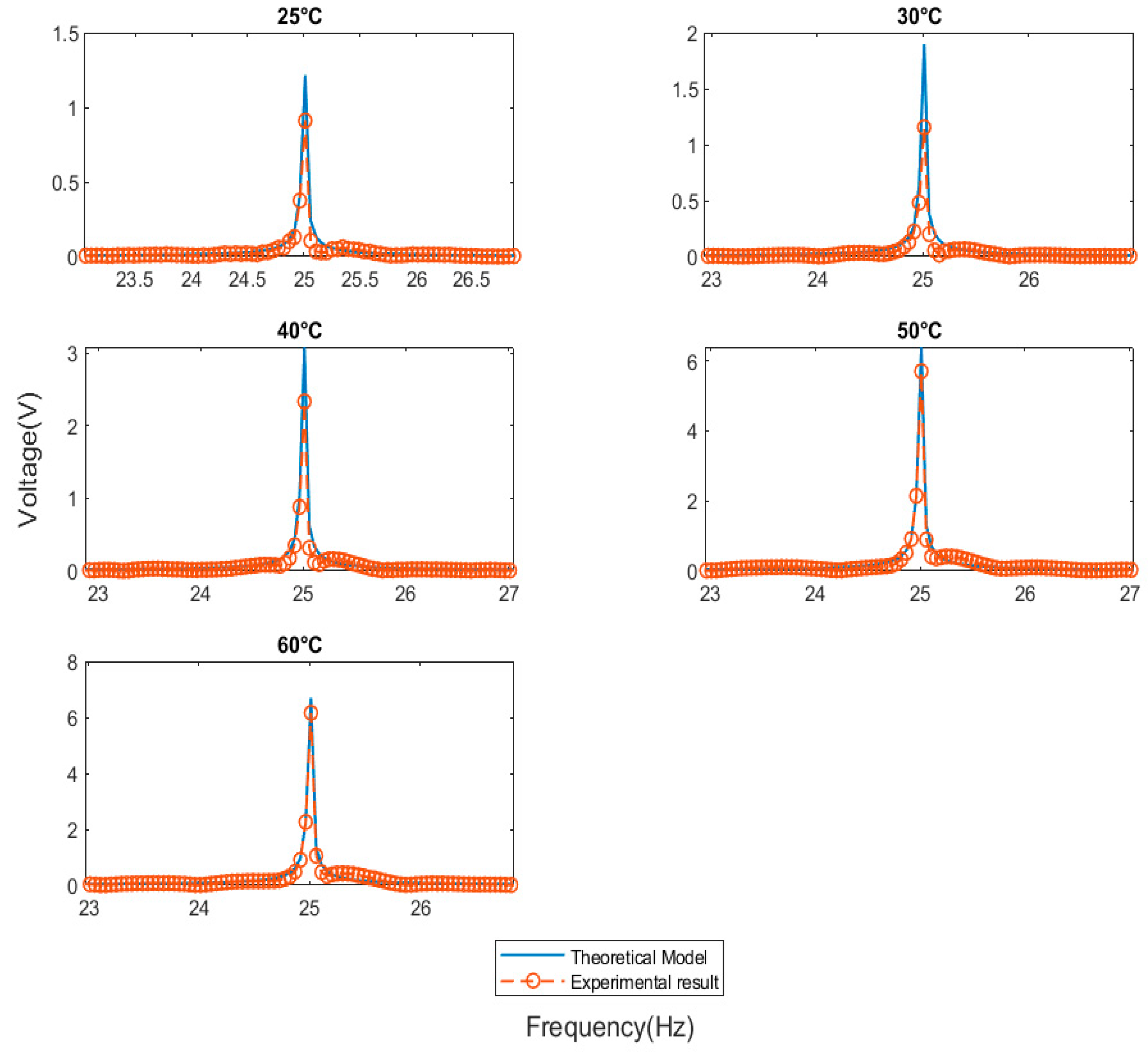
Figure 3 illustrates the system’s theoretical model voltage prediction which was consistent with experimental measurements. Three separate MFC piezoelectric transducers are laminated between layers of the epoxy glass composite, and each transducer is connected to a separate external resistor. The voltage drop at each resistor was recorded, and the average result was used for further analysis. The model was exposed to several moderate temperature environments (25 °C, 30 °C, 40 °C, 50 °C, and 60 °C). Because it was claimed that this alternative energy source would be used to harvest energy from our surroundings, the system was studied with a moderate environmental factor. The proposed mathematical model developed in this paper yielded highly consistent results in laboratory conditions. The laminated MFC was exposed to ambient temperature and frequency to investigate the dependence of certain parameters of the energy harvester system. The Curie temperature of the PZT fibers and the glass transition temperature of the epoxy used inside the MFC are the most important temperature limits. In reference [
31] the temperature behavior of the key piezoelectric parameters, such as the electromechanical coupling factor, dielectric permittivity, piezoelectric charge constants, and voltage constants of a piezoelectric material, were studied. Temperatures below 150 °C have no significant effect on these parameters, indicating that any transducer made from this material can be used successfully up to this temperature without losing its magnetic properties. Between 150 and 250 degrees Celsius, the piezoelectric properties (piezoelectric constant) undergo significant changes, primarily due to the depoling effect, and beyond that, at temperatures above 250 degrees Celsius, they degrade rapidly, tending to zero.
Figure 4 illustrates the frequency of excitation dependence of the MFC piezoelectric transducer. The graph depicts the voltage measurement at 40 degrees Celsius and five different frequencies.
The frequencies assumed in this work are low frequencies obtained from mechanical system vibration. The efficiency of mapping mechanical energy to electrical energy is more dependent on frequency than amplitude. According to the empirical data as well as the mathematical model, when the frequency of the excitation load is increased, the voltage that is obtained also increases in a proportional fashion.
To obtain a clearer picture of the results of the measurement, it is more practical to convert the responses into the frequency domain using the FFT (fast furrier transformation) algorithm.
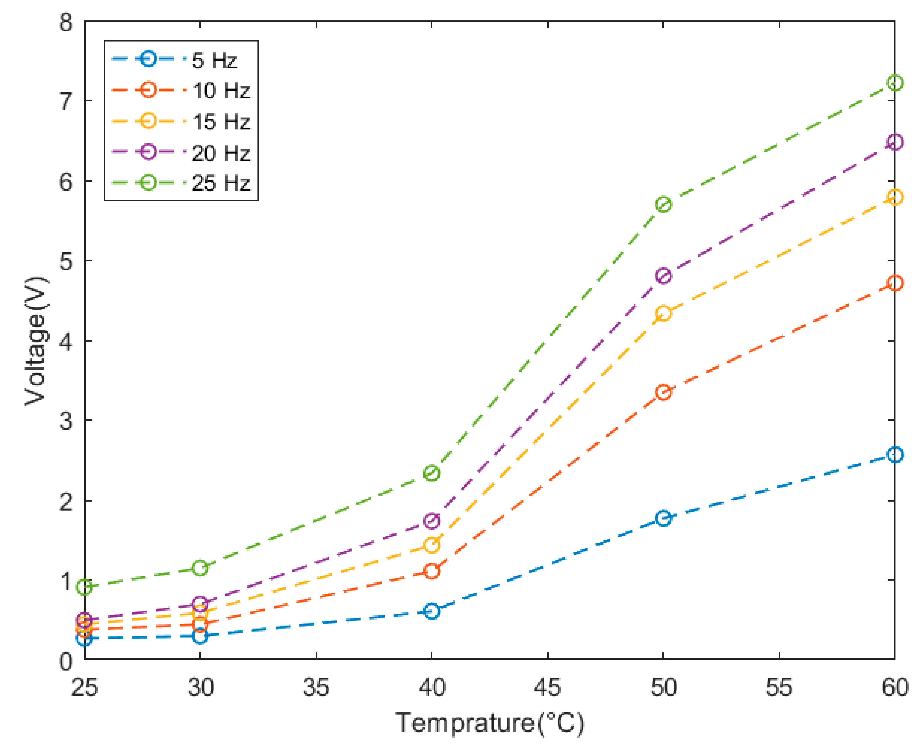
Figure 5 shows the frequency domain obtained by the FFT algorithm, which was used to sample data from the time domain into the frequency domain. According to
Figure 6, the voltage response of the laminated MFC piezoelectric transducer increases linearly as the temperature and frequency are increased. The graph demonstrates peak voltage measured 7.2 volts at its highest point at a frequency of 25 Hertz and a temperature of 60 degrees Celsius.
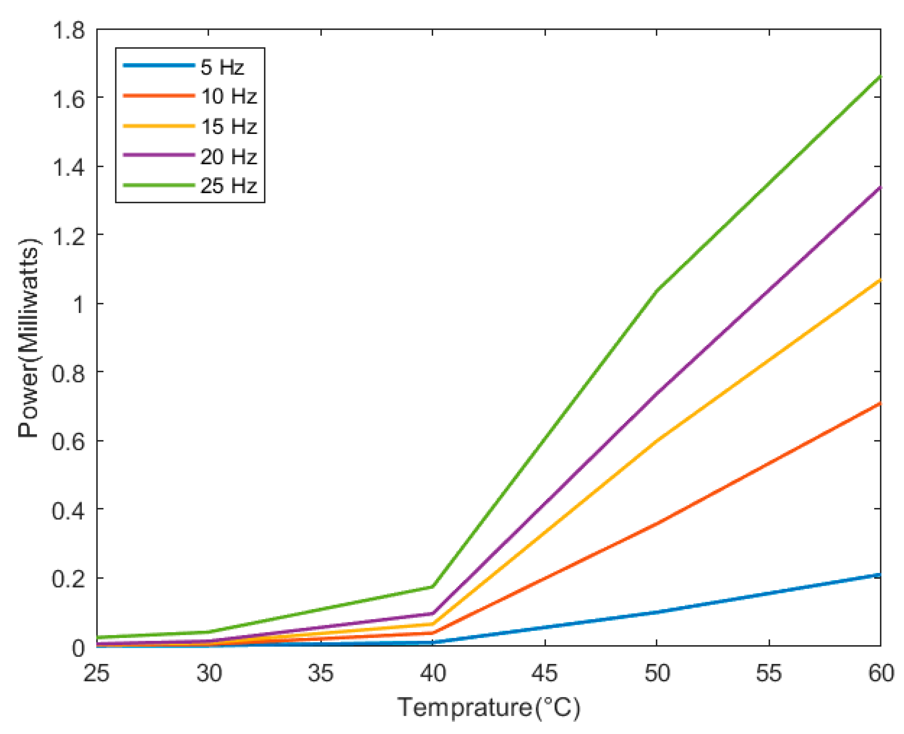
The simple supported harvester model and experimental results confirm that the two key parameters of the external loads (frequency and temperature) had the greatest influence on power efficiency (
Figure 7). As shown in the frequency domain on
Figure 6, as the temperature rises from 25 to 60 degrees Celsius, the voltage drop in the resistor increases smoothly. The same is true for the frequency of excitation; as the frequency increased, so did the amount of energy obtained. As the temperature rises, the thermal coefficients of the laminated MFC expands, influencing the strain induced. Although increasing temperature has an effect on dielectric coefficients [
28] the magnitude is small in comparison to thermal coefficients. The thermal expansion of the tested sample is more strongly influenced by an increase in temperature than the dielectric coefficient properties. Due to the dielectric property, it has been observed in a different paper [
28] that an increase in temperature results in a decrease in the efficiency of MFC piezoelectric transducers. On the other hand, in this research, we attempted to solve the problem by extending the model to include thermal expansion as a function of strain, as demonstrated by Equation (20). Because of the stress and the thermal expansion, the strain that is caused by this equation will be induced. According to the findings of this study, the thermal expansion of a material increases at a rate that is significantly higher than the rate at which its dielectric coefficient increases when the temperature increases. This causes the voltage to rise at the output of the transducer, which adds new findings to those obtained from the work carried out previously.
Figure 7 illustrates the relationship that exists between power, temperature, and frequency in the context of the results that were obtained.


