Article

Transmission Backlash Compensation and Grasping Force Estimation of Surgical Instruments for the Laparoscopic Minimally Invasive Surgery Robot

1
School of Electronic Engineering and Automation, Guilin University of Electronic Technology, Guilin 541004, China
2
School of Artificial Intelligence, Guilin University of Electronic Technology, Guilin 541004, China
*
Author to whom correspondence should be addressed.
Appl. Sci. 2022, 12(23), 12126; https://doi.org/10.3390/app122312126
Submission received: 7 November 2022 / Revised: 22 November 2022 / Accepted: 24 November 2022 / Published: 27 November 2022
(This article belongs to the Section Robotics and Automation)

Abstract

:
It is difficult to install the sensor on the end effector of a minimally invasive surgical robot with a narrow space within which to obtain the position and grasping force; thus, the elongation effect of cable-driven surgical instruments results in low precision control, which may damage the tissues and organs of patients. A novel transmission backlash compensation and grasping force saturation limitation algorithm based on the tension and displacement transmission model of a cable-pulley system is proposed to improve the operation’s accuracy and safety. The algorithm considers the force and position transmission characteristics of each stage of the cable-pulley system including the transition stage. Experimental verifications show that the proposed algorithm can significantly improve the position tracking accuracy of surgical instruments and the safety of grasping operations.

1. Introduction

Because of the advantages of flexible design, smooth transmission, high transmission efficiency and high reliability, cable-driven transmission has been widely used in robots, medical devices, and in other fields. The existing surgical instruments of minimally invasive surgical robots mainly use a cable-driven mechanism to transfer the displacement and grasping force. There are two main types of cable-driven transmissions. The first type is a cable-pulley mechanism, in which the pulley is used to change the direction of the cable, with more pulleys needed when the transmission path is complex. Another type is the tendon-sheath mechanism, which can be configured arbitrarily in the transmission’s routing; this has greater nonlinearity because the friction of tendon-sheath transmissions is usually greater than that of cable-pulley transmissions. Both types of cable-driven transmission are applied in various surgical robotic systems, such as the da Vinci system [1,2,3], MASTER system [4,5], Endoscopes robot [6,7], and the Medrobotics Flex system [8]. Since sensors cannot tolerate the harsh chemical environment of sterilization processes, it is uneconomical to use the comparatively expensive force sensor for instruments that can only be used a few times. In addition, the end effectors of surgical instruments are complex and small in size, so it is difficult to install a force sensor and position encoder directly to carry out the closed-loop control required for force and position [9].
In order to control the position and distal end force of a minimally invasive surgical robot, another feasible scheme is to establish an accurate cable-driven model to estimate the position and force information of the end effector of surgical instruments. There are two widely studied cable-driven models, one is the cable-pulley model, and the other is the tendon-sheath model, which has been studied by more scholars. For the tendon-sheath transmission model, Kaneko et al. proposed a lumped mass numerical model for the tension transmission and first formulated the transmission characteristics with apparent tendon-stiffness and equivalent backlash [10]. Palli et al. presented a viscoelastic mode that describes the tendon-sheath driving system with a lumped parameters model, and also proposed a control strategy to compensate for the nonlinear effects [11,12]. Do et al. proposed an asymmetric backlash hysteresis model that characterized the transmission phenomena of the tendon-sheath mechanism during the loading and unloading phases for endoscopic systems, and an efficient parameter identification method was used to estimate the model’s parameters [13,14]. Chi Yen Kim et al. derived a dynamic model of a coupled cable-pulley structure while considering the material tensile characteristics of the cable; this model derived an estimate of the operating force of the end effector as well as the states of all inner pulleys without encoders [15]. L.S. Chiang et al. presented a method with which to estimate the end effector parameters using only a force and position sensor at the proximal site [16]. Agrawal et al. proposed the mathematically rigorous distributed parameter model for cable-conduit actuation with any curvature and initial tension profile across the cable, which is described by a set of partial differential equations in the continuous time-domain, and is also discretized for its effective numerical simulation of cable motion and tension transmission across the cable [17]. Wu H et al. proposed a real-time position compensation control method based on the deformation of flexible cables, by establishing a torque transmission model of double tendon-sheaths under arbitrary load conditions, and developed two open-loop control strategies for friction and deformation compensation [18]. Farshad et al. proposed a new motion transmission model of a tendon-sheath pulley mechanism to estimate the motion error and force of da Vinci system surgical instruments, and used this model for the position control of the instrument tip to eliminate hysteresis and achieve an accurate trajectories track [19,20].
For the cable-pulley transmission model, Jung et al. conducted more rigorous analyses to improve the classical capstan equation by including both rod bending rigidity and power-law friction into the formula, and also investigated the effects of important parameters on tension transmission efficiency [21,22]. Lu et al. proposed analytical methods for predicting the transmission capability of a precise cable drive including the bending rigidity, and also developed the analytical methods required to predict the transverse oscillation frequency of a precise cable drive to enable designers to better assess dynamic performance in the design study phase [23,24]. Miyasaka et al. proposed a method for modeling a closed-circuit cable-pulley-driven robotic system with a hysteresis cable tension model and a cable-pulley network friction model. The Hysteresis Cable Tension Model captures the cable response, including elasticity, internal friction, material damping, and hysteresis. The modeling method was validated on the RAVEN II robotic surgery platform [25,26]. Wang et al. proposed a joint torque disturbance observer (JTDO)-based method for estimating the clamping force of the end effector of a cable-driven surgical robot. The JTDO Variation proposed the cable tension between the actual cable tension and the estimated cable tension using a Particle Swarm Optimization Back-Propagation Neural Network [27]. Guo et al. proposed a grasping force sensing method based on a denoising Auto Encoder Neural Network (dAENN), which uses encoder and motor current readings as the input for the dAENN, to learn the nonlinear mapping between the compact features and the grasping force labels [28]. Liang proposed an improved scheme based on a fed neural network and a prediction model, to eliminate the coupled motion of the end effector and reduce position tracking error [29]. Based on the dynamic model of the cable-pulley system, Y. Li et al. used the motor encoder and motor torque information as the observed values of the Unscented Kalman filter to jointly estimate the grasping force and grasper position of slender cable-driven surgical instruments [30]. Xue et al. used an improved cable-pulley model to compensate for the recoil of minimally invasive surgical instruments and estimated the distal force of the end effector, but did not consider the transition state of the rope pulley drive, and its static assumption of the guide pulley on the transmission path Thus, it does not match the actual situation of most surgical instruments [31,32].
In summary, for the cable-driven mechanism with a simple transmission path, the cable-pulley transmission model has higher transmission efficiency than the tendon-sheath transmission model. When using the cable-pulley model to analyze the force and position transmission characteristics, few existing studies quantitatively analyze the force and position transmission characteristics of the cable-driven system in the transition state. Therefore, this paper will establish a force and position transfer model for the cable-pulley system considering the transition stage, and realize the efficient calculation of the movement hysteresis and output torque of surgical instruments based on this model.

2. Materials and Methods

There are generally four degrees of freedom for surgical instruments in laparoscopic minimally invasive surgery robots, in which one is the rotation freedom of the operation rod, one is the rotation freedom of the wrist, and the other two degrees of freedom are the rotation freedom of the two graspers. The transmission structure of surgical instruments is shown in Figure 1, wherein, P 0 and P 5 are the driving pulley and driven pulley, respectively, and P 1 , P 2 , P 3 and P 4 are idler pulleys. The cables of surgical instruments consist of two parts: the non-contact segment and wrapped segment. The non-contact segment of the cable is relatively long, which plays a dominant role in the position transmission characteristics of the surgical instruments, while the wrapped cable segment plays a decisive role in the force transmission characteristics of surgical instruments.

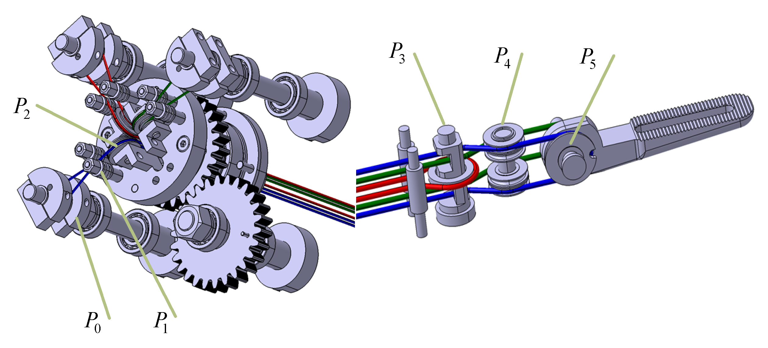
2.1. Single-Cable-Pulley Transmission

Figure 2 is a schematic diagram of the transmission of an infinitesimal cable segment of a single cable-pulley system with a given length dl = Rdθ at an angular position θ. The tangential forces on both sides of the infinitesimal cable segment are T and T + dT, the shear forces are Q and Q + dQ, and the bending moments around the rotation center O are M and M + dM, respectively. The infinitesimal cable segment is subjected to the normal force dN and friction dFu varying with the angular position θ. If the inertia force of the infinitesimal cable segment is neglected, the force balance and the moment balance equation around the center of rotation can be obtained as follows:
{ ( T + d T ) cos d θ 2 T cos ( d θ 2 ) Q sin d θ 2 + ( Q + d Q ) sin d θ 2 d F u = 0 ( Q + d Q ) cos d θ 2 Q cos d θ 2 ( T + d T ) sin d θ 2 T sin ( d θ 2 ) + d N = 0 ( M + d M ) M ( Q + d Q ) R d θ 2 Q R d θ 2 + r d F u = 0 ,
where r , r 1 and R are, respectively, the cable radius, the pulley radius and the bending radius of the cable, T 1 and T 2 are the incoming tension and outcoming tension, and θ s l i p and θ w r a p are the slip angle and wrap angle, respectively.
Since is infinitely small, cos ( d θ / 2 ) 1 and sin ( d θ / 2 ) d θ / 2 , Equation (1) can be simplified as:
{ d T + Q d θ d F u = 0 d Q T d θ + d N = 0 d M Q R d θ + r d F u = 0 ,
Since the movement of the cable on the pulley is a sliding one between the rigid bodies, Amontons’ law of friction can be used, and then the following can be calculated as:
d F u = μ d N ,
where μ is the friction coefficient.
As the bending stiffness is considered, the cable is modeled as a linear elastic material, so the bending constitutive equation [33] of the cable is as follows:
M = E I R = E R π r 4 4 ,   d M = 0 ,
where E and I are the tensile modulus and cross-sectional area of the cable, and M is the bending moment of the cable.
Substituting Equations (3) and (4) into Equation (2), the following expression is obtained:
d T + ( Q μ T ) d θ + μ d Q = 0 ,
Q = r r 1 d T d θ = 1 ρ d T d θ ,
where ρ = r1/r is the radius ratio of the pulley to the cable.
Substituting Equation (6) into Equation (5) can yield:
μ d 2 T d θ 2 + ( 1 + ρ ) d T d θ ρ μ T = 0 ,
Equation (7) is a second-order linear ordinary differential equation whose general solution can be expressed as:
T ( θ ) = C 1 e a θ + C 2 e b θ ,
T ( θ ) = C 1 e a θ + C 2 e b θ ,   b = 1 ρ ( 1 + ρ ) 2 + 4 μ 2 ρ 2 μ < 0
To determine the constant C 1 and C 2 , the boundary conditions of Equation (8) need to be known. According to [34], the boundary condition of Equation (8) is:
{ ϑ 0 Q ( 0 ) = T 1 sin ϑ = 0 T ( 0 ) = T 1 cos ϑ = T 1 ,
where Q ( 0 ) and T ( 0 ) are the incoming shear force and the incoming tension force in the contact region, respectively, and ϑ is the inclined angle of the outcoming cable, which is zero in the contact region.
Combining Equations (6) and (9), the following can be formulated as:
{ T ( 0 ) = T 1 d T d θ | θ = 0 = ρ Q ( 0 ) = 0 ,
Combining Equations (8) and (10) can yield:
C 1 = b T 1 b a ,   C 2 = a T 1 a b ,
Let λ ( ρ , μ , θ ) = ( a e b θ b e a θ ) / ( a b ) , and by substituting Equation (11) into Equation (8), the following can be obtained as:
T ( θ ) = T 1 λ ( ρ , μ , θ ) = T 1 ( 1 ρ + ( 1 + ρ ) 2 + 4 μ 2 ρ 2 ( 1 + ρ ) 2 + 4 μ 2 ρ exp ( 1 ρ ( 1 + ρ ) 2 + 4 μ 2 ρ 2 μ θ ) + 1 + ρ + ( 1 + ρ ) 2 + 4 μ 2 ρ 2 ( 1 + ρ ) 2 + 4 μ 2 ρ exp ( 1 ρ + ( 1 + ρ ) 2 + 4 μ 2 ρ 2 μ θ ) ) ,
Since the tension ratio on both sides of the pulley is related to the direction of the cable moving on the pulley, it is defined that:
T 2 = { T 1 / λ ( ρ , μ , θ s l i p ) ,   i f   sgn ( θ ˙ i n ) = 1   T 1 λ ( ρ , μ , θ s l i p )   ,   other ,
As the cable subjected to tensile force is elastically elongated, according to Hooke’s law, the strain generated in the infinitesimal cable segment can be expressed as:
ε ( θ ) = d δ R d θ = T ( θ ) E A     d δ = T ( θ ) R E A d θ ,
where T ( θ ) , ε ( θ ) , and d δ are the tension, stress and strain of the infinitesimal cable segment at position θ, respectively.
As the cable is preloaded by the tension T p r e , the cable elongation caused by the change of the outcoming force T p r e can be formulated as:
Δ L = L T 2 L T p r e ,
Figure 3a is the tension distribution diagram of the cable in the process of loading. Combining Equations (12)–(14), the following can be formulated as:
Δ L = 0 θ s l i p T ( θ ) R E A d θ T p r e R E A θ s l i p = { T 1 R φ ( ρ , μ , θ s l i p ) E A λ ( ρ , μ , θ s l i p ) T p r e R E A θ s l i p , i f sgn ( θ ˙ i n ) = 1 T 1 R E A φ ( ρ , μ , θ s l i p ) T p r e R E A θ s l i p , o t h e r   ,
where φ ( ρ , μ , θ s l i p ) = 0 θ s l i p ( a e b θ b e a θ ) d θ / ( a b ) .
Figure 3b is the tension distribution diagram of the cable in the process of unloading. The outcoming tension is firstly increased from T 1 to T p k , and then gradually reduced to T 2 . At this time, the cable only partially moves on the pulley.
For the cable between the intervals θ s l i p α θ θ s l i p , the following is obtained from the Equation (12) as:
T b = T p k / λ ( ρ , μ , α ) = T 2 λ ( ρ , μ , α )   T b = T p k T 2 ,
λ ( ρ , μ , α ) = T p k / T 2 ,
From Equation (15), the cable elongation in the sliding interval θ s l i p α θ θ s l i p can be expressed as:
Δ L α = { T b R φ ( ρ , μ , α ) E A T p r e R E A α ,   i f   sgn ( θ ˙ i n ) = 1 T b R φ ( ρ , μ , α ) E A λ ( ρ , μ , α ) T p r e R E A α ,   o t h e r ,
where sgn( θ ˙ i n ) denotes the direction of the cable moving on the pulley; if the cable moves counterclockwise on the pulley, then sgn( θ ˙ i n ) = 1, otherwise sgn( θ ˙ i n ) = 0.
From Equation (15), the cable elongation in the sliding interval 0 < θ θ s l i p α is:
Δ L ( θ s l i p α ) = { T 1 R φ ( ρ , μ , ( θ s l i p α ) ) E A λ ( ρ , μ , ( θ s l i p α ) ) T p r e R E A ( θ s l i p α ) , i f   sgn ( θ ˙ i n ) = 1 T 1 R E A φ ( ρ , μ , ( θ s l i p α ) ) T p r e R E A ( θ s l i p α ) , o t h e r ,
From Equations (19) and (20), the total elongation of the cable can be calculated as:
Δ L = Δ L α + Δ L ( θ s l i p α ) = { T p k T 2 R φ ( ρ , μ , α ) E A + T 1 R φ ( ρ , μ , ( θ s l i p α ) ) E A λ ( ρ , μ , ( θ s l i p α ) ) T p r e R E A θ s l i p , i f   sgn ( θ ˙ i n ) = 1 T p k T 2 R E A φ ( ρ , μ , α ) λ ( ρ , μ , α ) + T 1 R E A φ ( ρ , μ , ( θ s l i p α ) ) T p r e R E A θ s l i p , o t h e r ,
As shown in Figure 4, there are three types of supports for the pulley: (a) fixed to the base; (b) rotating around the pulley shaft; and (c) rotating around the rolling bearing. Therefore, the tension loss F l o s s on both sides of the pulley is mainly caused by the friction F c between the cable and the pulley or the friction F s between the pulley and the pulley shaft, which can be calculated as:
F l o s s = min { F c , F s } = T 2 T 1 ,
For the pulley of type (a), the tension loss can be calculated from Equation (12) as:
F l o s s = F c = T 2 T 1 = T 1 ( λ ( ρ , μ , θ w ) 1 ) ,
where θ w is the wrap angle of the cable wrapped on the pulley.
For the pulley of type (b), if Fs > Fc, then F l o s s = F c = T 1 ( λ ( ρ , μ , θ w ) 1 ) ; if F s < F c , then F l o s s = F s , and the friction F s between the pulley and pulley shaft can be expressed as:
{ F s = μ s N s x 2 + N s y 2 = μ s T 1 2 + T 2 2 2 T 1 T 2 cos ( θ w ) N s x = T 1 sin ( θ w ) N s y = T 1 cos ( θ w ) + T ,
where Ns is the normal force applied by the shaft to the pulley, whose components in the x and y directions are represented by N s x and N s y , r s is the shaft radius, T 1 and T 2 are the tension of the cable on both sides of the pulley, and μ s is the friction coefficient between the pulley and shaft.
As shown in Figure 4b, the applied external moment causes the driven cable to move clockwise along the pulley, ignoring the moment of inertia of the cable-pulley system, the following formula that describes the change of tension along the driven pulley can be formulated as:
( M l o a d r s F s ) = R ( T 2 T 1 ) ,
Substituting Equation (24) into Equation (25) can yield:
M l o a d R + T 1 T 2 = r s R μ ˜ s T 1 2 + T 2 2 2 T 1 T 2 cos ( θ w ) ,
where μ ˜ s = μ s sgn ( θ ˙ ) is the signed friction coefficient used instead of μ s , as the direction of the frictional force F s is related to the direction of the rotation of the driven pulley, if the cable moves clockwise along the driven pulley, then sgn ( θ ˙ ) = 1 , otherwise sgn ( θ ˙ ) = 1 .
Let λ = T 1 / T 2 , according to Equation (26), then the following can be formulated as:
( M l o a d T 1 R + 1 ) λ 1 = r s μ ˜ s R λ 2 + 1 2 λ cos ( θ w ) ,
Let k = ( M l o a d / ( T 1 R ) + 1 ) , γ = ( r s μ ˜ s / R ) 2 , w = cos ( θ w ) , then Equation (25) can be expressed as:
( k 2 γ ) λ 2 + 2 ( γ w k ) λ + ( 1 γ ) = 0 ,
Since 0 < λ < 1 , Equation (28) can be solved as:
λ = ( k γ w ) ( k γ w ) 2 ( k 2 γ ) ( 1 γ ) ( k 2 γ ) ,
For the idler pulley, Mload = 0, k = 1, then Equation (29) can be expressed as:
λ = ( 1 γ w ) ( 1 γ w ) 2 ( 1 γ ) ( 1 γ ) ( 1 γ ) ,
Equation (30) shows that the slip angle of the cable along the idler pulley is independent of the friction coefficient μ c of the cable moving along the driven pulley, and it is related to the friction coefficient μ s between the idler pulley and its support shaft. For the specified idler pulley, μ s is a constant; therefore, the slip angle of the cable moving along the idler pulley is a constant.

2.2. Displacement and Tension Transmission Characteristics of a Closed-Circuit Cable-Pulley System

The displacement and tension transmission between the driving pulley and the driven pulley are generally closed-circuit cable-pulley systems. To derive the closed-circuit cable-pulley model, we assume that:
(1)
The applied moment is always positive.
(2)
The cable in symmetrical configuration does not go slack.
(3)
The tension of all the infinitesimal cable segments is the same under initial pretension loads.
As shown in Figure 5, it is a closed-circuit cable-pulley system consisting of cable T, cable B and 10 pulleys. The radius of the cable is r, the friction coefficient of the cable moving along the pulleys is μ c , and the pulley P 0 and P 5 are, respectively, the driving pulley and the driven pulley, whose radii are, respectively, R 0 and R 5 , the pulley rotates around its support rolling bearing, and the pulley P i t , i = 1, 2, 3, 4 are the idler pulleys driven by the cable T, and their corresponding bending radius, sliding angle and wrap angle are, respectively, R i t , θ s , i t and θ w , i t , the tension on both sides of the pulley P i t are T i 1 , i t and T i , i + 1 t , respectively, and the tangent length between the pulley P i t and P i + 1 t is L i , i + 1 t ; the pulley P i b , i = 1,2,3,4 are the idler pulleys driven by the cable B, their corresponding bending radius, sliding angle and package are R i b , θ s , i b and θ w , i b , respectively, and the tension on both sides of the P i b are T i 1 , i b and T i , i + 1 b , respectively, and the tangent length between the pulley and P i + 1 b is L i , i + 1 b .
The closed-circuit cable-pulley transmission system can be regarded as a double-tendon-sheath transmission system with a constant curvature radius of the sheath. According to the literature [16,33], the tension and displacement transmission characteristics of the closed-circuit cable-pulley system are shown in Figure 6, mainly by three different phases, which are composed of the following: (1) working phase (III), where the output torque and displacement on the driven pulley is almost linear with the input torque and displacement on the driving pulley, and both cables are in a state of motion. (2) Delay phase (I), which occurs after the direction of movement of the driving pulley changes, since only the two cables are partially in motion, the tension changes in the driving pulley cannot be immediately propagated to the driven pulley, and the output torque and displacement on the driven pulley does not change with the input position on the driving pulley. (3) Transition phase (II, IV), which refers to the interval from the delay phase to the work phase or from the work phase to the delay phase, in which the output torque and position changes on the driven pulley are substantially linear, but its slope is less than that of the working phase.

2.3. Closed-Circuit Cable-Pulley System Transmission Backlash and Grasping Force Estimation

When the speed of the cable moving along the pulley is greater than that of the pulley moving around its support shaft, the cable will exhibit elastic slip along the driven pulley, since the pre-tensioned cable T and the cable B are, respectively, fixed to the driving pulley (point C t and point C b ) and to the driven pulley (point D); there is no elastic slip along the driving pulley and the driven pulley, and the elongation of the cable along the driving pulley and the driven pulley can be ignored.
It is assumed that the pretension of cable T and cable B are T p r e t and T p r e b , respectively; when there is no external exerted torque, the tensions of cable T and cable B on both sides of the pulley are, respectively:
{ T 0 , 1 t = T 1 , 2 t = = T 4 , 5 t = T p r e t T 0 , 1 b = T 1 , 2 b = = T 4 , 5 b = T p r e b ,
Assume that the driving pulley exerted external torque and rotates counterclockwise; ignoring the moment of inertia of the cable-pulley system, the following formulas can be obtained as:
M i n = ( T 0 , 1 t T 0 , 1 b ) R 0 ,
M o u t = ( T 4 , 5 t T 4 , 5 b ) R 5 ,
Defining η { t , b } , λ j η = λ ( ρ j η , μ j , θ s , j η ) , ρ j η = r j η / r , K i , 0 η = 1 , K i , m η = j = i m λ j η , and from Equation (12), the following can be obtained as:
{ T i , i + 1 t = { T 0 , 1 t / K 1 , i t ,   i f sgn ( θ ˙ i n ) = 1 T 0 , 1 t K 1 , i t ,   o t h e r T i , i + 1 b = { T 0 , 1 b K 1 , i b ,   i f sgn ( θ ˙ i n ) = 1 T 0 , 1 b / K 1 , i b ,   o t h e r ,
Substituting Equation (34) into Equation (33), the following can be formulated as:
{ M o u t = ( T 0 , 1 t / K 1 , 4 t T 0 , 1 b K 1 , 4 b ) R 5 ,   i f sgn ( θ ˙ i n ) = 1 M o u t = ( T 0 , 1 t K 1 , 4 t T 0 , 1 b / K 1 , 4 b ) R 5 ,   o t h e r ,
According to the geometric constraint relationship of the closed-circuit cable-pulley system, the following formulas can be yielded as:
Δ L t + Δ L b = 0 ,
Δ θ o u t = Δ L t / R 5 = Δ L b / R 5 ,
Δ L t = θ i n R 0 θ o u t R 5     θ o u t = θ i n R 0 / R 5 Δ θ o u t ,
where Δ L t and Δ L b are the total elongation of cable T and cable B, respectively.

2.3.1. Cable Elongation and Grasping Force of the Cable-Pulley System during the Working Phase

Assuming that the system is in the working stage at time t 1 , the tension T 0 , 1 t of cable T increases (decreases) while the tension T 0 , 1 b of cable B decreases (increases), when the external torque Min drives the driving pulley to rotate counterclockwise (clockwise).
From Equation (15), it can be obtained as follows:
{ Δ L t o t a l t = T 0 , 1 t κ 11 E A T p r e t L t o t a l t E A ,   i f sgn ( θ ˙ i n ) = 1 Δ L t o t a l t = T 0 , 1 t κ 21 E A T p r e t L t o t a l t E A ,   other   ,
Δ L t o t a l b = { T 0 , 1 b κ 12 E A T p r e b L t o t a l b E A ,   i f sgn ( θ ˙ i n ) = 1 T 0 , 1 b κ 22 E A T p r e b L t o t a l b E A ,   other ,
where L t o t a l t = L 0 , 1 t + i = 1 4 ( L i , i + 1 t + θ s , i t ) , L t o t a l b = L 0 , 1 b + i = 1 4 ( L i , i + 1 b + θ s , i b ) , κ 11 = L 0 , 1 t + i = 1 4 ( L i , i + 1 t K 1 , i t + R i t φ ( ρ i t , μ c , θ s i t ) K 1 , i t ) , κ 12 = L 0 , 1 b + i = 1 4 ( L i , i + 1 b K 1 , i b + R i b K 1 , i 1 b φ ( ρ i b , μ c , θ s i b ) ) , κ 21 = L 0 , 1 t + i = 1 4 ( L i , i + 1 t K 1 , i t + R i t K 1 , i 1 t φ ( ρ i t , μ c , θ s i t ) ) , κ 22 = L 0 , 1 b + i = 1 4 ( L i 1 , i b K 1 , i b + R i b φ ( ρ i b , μ c , θ s i b ) K 1 , i b ) .
Substituting Equations (39) and (40) into Equation (36), it can be obtained as follows:
{ T 0 , 1 t κ 11 + T 0 , 1 b κ 12 κ 3 = 0 ,   i f sgn ( θ ˙ i n ) = 1 T 0 , 1 t κ 21 + T 0 , 1 b κ 22 κ 3 = 0 , o t h e r ,
where κ 3 = T p r e t L t o t a l t + T p r e b L t o t a l b .
Substituting Equation (32) into Equation (41) yields:
{ T 0 , 1 t = κ 3 ( κ 11 + κ 12 ) + M i n R 0 κ 12 ( κ 11 + κ 12 ) ,   i f sgn ( θ ˙ i n ) = 1 T 0 , 1 t = κ 3 ( κ 21 + κ 22 ) + M i n R 0 κ 22 ( κ 21 + κ 22 ) ,   o t h e r ,
{ T 0 , 1 b = κ 3 ( κ 11 + κ 12 ) M i n R 0 κ 11 ( κ 11 + κ 12 ) ,   i f sgn ( θ ˙ i n ) = 1 T 0 , 1 b = κ 3 ( κ 21 + κ 22 ) M i n R 0 κ 21 ( κ 21 + κ 22 ) ,   o t h e r ,
Substituting Equations (42) and (43) into Equation (35), the following can be obtained:
{ M o u t = M i n R 5 R 0 ( K 1 , 4 t K 1 , 4 b κ 11 + κ 12 ) K 1 , 4 t ( κ 11 + κ 12 ) + ( 1 K 1 , 4 t K 1 , 4 b ) R 5 κ 3 K 1 , 4 t ( κ 11 + κ 12 ) ,   i f sgn ( θ ˙ i n ) = 1 M o u t = M i n R 5 R 0 ( κ 21 + K 1 , 4 t K 1 , 4 b κ 22 ) K 1 , 4 b ( κ 21 + κ 22 ) ( 1 K 1 , 4 t K 1 , 4 b ) R 5 κ 3 K 1 , 4 b ( κ 21 + κ 22 ) ,   o t h e r ,
Combining Equations (37) and (41)–(43), the transmission backlash of the cable-pulley system can be calculated as:
Δ θ o u t = { M i n κ 11 κ 12 E A R 0 R 5 ( κ 11 + κ 12 ) + ( T p r e b L t o t a l b κ 11 T p r e t L t o t a l t κ 12 ) E A R 5 ( κ 11 + κ 12 ) ,   i f sgn ( θ ˙ i n ) = 1 M i n κ 21 κ 22 E A R 0 R 5 ( κ 21 + κ 22 ) + ( T p r e b L t o t a l b κ 21 T p r e t L t o t a l t κ 22 ) E A R 5 ( κ 21 + κ 22 ) ,   other ,
Substituting Equation (45) into Equation (38), the output displacement of the cable-pulley system can be expressed as:
{ θ o u t = θ i n R 0 R 5 ( M i n κ 11 κ 12 E A R 0 R 5 ( κ 11 + κ 12 ) + ( T p r e b L t o t a l b κ 11 T p r e t L t o t a l t κ 12 ) E A R 5 ( κ 11 + κ 12 ) ) ,   i f sgn ( θ ˙ i n ) = 1 θ o u t = θ i n R 0 R 5 ( M i n κ 21 κ 22 E A R 0 R 5 ( κ 21 + κ 22 ) + ( T p r e b L t o t a l b κ 21 T p r e t L t o t a l t κ 22 ) E A R 5 ( κ 21 + κ 22 ) ) , o t h e r ,

2.3.2. Cable Elongation and Grasping Force of the Cable-Pulley System during the Delay and Transition Phases

To derive the formulas of the elongation of the cable-pulley system during the delay and transition phases according to Equations (21) and (36)–(38), it is necessary to solve the 4th nonlinear equations, which are very complicated and difficult to solve. In order to simplify the analysis process, the cable elongation and grasping force of the cable-pulley system during the delay phase and the transition phase are taken into consideration in a unified way. When at time t0, the driving pulley transitions from the counterclockwise working phase to the delay and transition phases, if and only if the direction of the torque M i n ( t 1 ) driving the driving pulley changes, and the direction of the speed θ ˙ i n ( t 1 ) of the driving pulley does not change, and the tension on both sides of the driven pulley satisfies T 4 , 5 t ( t 0 1 ) > T 4 , 5 b ( t 0 1 ) , then the cable-pulley system is in the delayed and transitional phases. At this time, the output displacement and output torque of the driven pulley remain unchanged, that is, θ o u t ( t 0 ) and M o u t ( t 0 ) . Using a similar analysis, a similar conclusion can be inferred when the driving pulley changes from a clockwise working phase to the delay and transition phases.
According to the above analysis, the calculation formulas of the output displacement and torque of the cable-pulley system during the entire transmission phase can be obtained as:
{ M o u t ( t 1 ) = ( 1 f l a g ) M o u t ( t 1 ) + M o u t ( t 0 ) f l a g θ o u t ( t 1 ) = ( 1 f l a g ) θ o u t ( t 1 ) + θ o u t ( t 0 ) f l a g f l a g = ( 1 ssgn ( θ ˙ i n ( t 1 ) M i n ( t 1 ) ) ) ssgn ( θ ˙ i n ( t 1 ) ( T 4 , 5 t ( t 1 ) T 4 , 5 b ( t 1 ) ) ) M o u t ( t 0 ) ,
where M o u t ( t 0 ) and M o u t ( t 1 ) are the output torque of the cable-pulley system at time t 0 and t 1 , respectively; θ o u t ( t 0 ) and θ o u t ( t 1 ) are the output displacements of the cable-pulley system at time t0 and t1, respectively; and the angular velocity of the driving pulley, ssgn(.) = 0.5 + 0.5 sgn(.) is a switch function.
Combining Equations (25) and (47), the output grasping torque M g r a s p can be calculated as:
M g r a s p = M o u t M f r i c ,

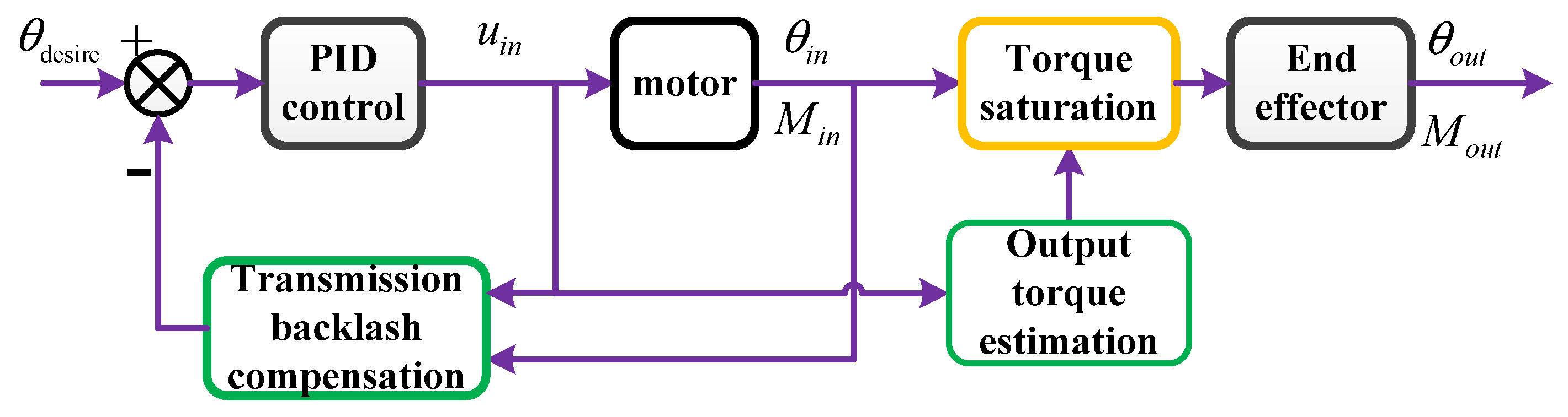
2.4. Feedforward Compensation Control for the Transmission Backlash of the Cable-Pulley System

During the operation, due to the elongation of the cable, the grasper of the surgical instruments will loosen after each grasping operation, which seriously affects the continuity of the operation. Therefore, it is necessary to compensate for the transmission backlash of the end effector of the surgical instrument during the grasping operation. At the same time, the estimated output torque of the cable-pulley system can be used to limit the movement of the end effector driven by the motor, thereby avoiding the excessive grasping force exerted by the distal grasper that can cause soft tissue damage. Figure 7 illustrates the force and position control flow of the distal driven grasper of the cable-pulley system, in which the position signal is added by the desired position and the backlash compensation is successively controlled by the PID controller and limited by the torque saturator. Then, the safe and accurate position control and grasping force limitation of the distal driven grasper of the cable-pulley system can be completed.
From Equation (39), the transmission backlash compensation can be formulated as:
θ com p = Δ θ o u t R 5 / R 0 ,

3. Experiments and Results

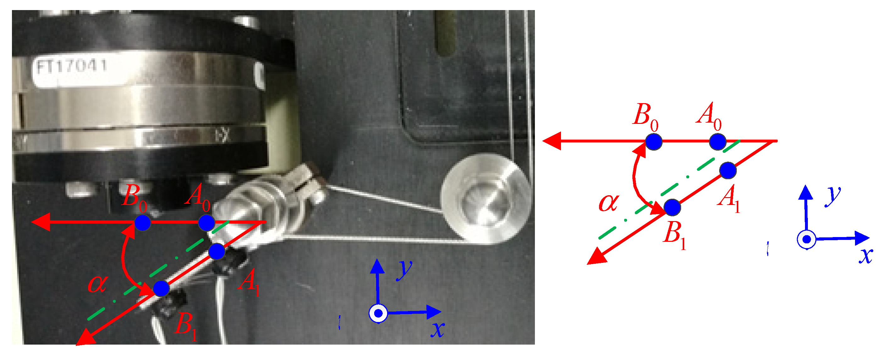
3.1. Experimental Setup

In order to validate the tension and displacement transmission characteristics of the closed-circuit cable-pulley system, a dedicated experimental platform similar to the transmission structure of the end effector of surgical instruments was designed. As shown in Figure 8, the dedicated experimental platform includes a closed-loop cable-pulley system, a motion control system, and a displacement and force measuring system, in which a maxon motor is driven by an elmo driver to drive the driving pulley, a Gmax controller using the EtherCat protocol is used to realize the communication between the industrial computer and the elmo driver, and a digital dynamometer is used to measure the pretension of the cable-pulley system. The NDI Polaris system (Northern Digital Inc., Waterloo, ON, Canada) was used to measure the output displacement of the cable-pulley system, and the ATI six-dimensional force sensor (Analytical Technology Inc., Collegeville, PA, USA) was used to measure the output torque of the distal grasper of the cable-pulley system. The device’s specific description is listed in Table 1.
Since the slip angle of the cable moving along the pulley does not exceed its wrap angle, when the pulley cannot rotate, the slip angle of the cable is equal to its wrap angle, and the tension ratio on both sides of the pulley can be calculated from Equation (13). When the pulley is rotatable, the slip angle of the cable on the pulley must be smaller than the wrap angle, and the tension ratio on both sides of the pulley can be calculated from Equation (29). The slip angle of cable T and cable B moving along the pulleys, and the tension ratios on both sides of the pulleys are, respectively, calculated and listed in Table 2.
It can be seen from the data in Table 3 that when the pulley is fixed or rotatable, the tension ratio on both sides of the pulley changes greatly. According to Equation (30), for a given idler pulley, the shaft friction coefficient is substantially the same, and the idler pulley radius is not much different, so the tension ratio on both sides of the idler pulley is substantially close. Knowing the ratio of the tension on both sides of the pulley, it is very difficult to solve the sliding angle of the cable moving along the pulley from Equation (12), which can be solved by the classical Capstan equation.

3.2. Measurement of the Output Displacement and Torque of the Distal Grasper of the Cable-Pulley System

Because there is no position encoder installed on the distal grasper of the cable-pulley system, its angle displacement needs to be measured by an NDI optical stereo positioner. The coordinate system of the mark points of the NDI optical stereo positioner is shown in the lower right corner of Figure 9. The positions of the two markers located on the distal grasper are represented by A and B, respectively. The initial position of the grasper at time t0 is represented by vector a = < A 0 , B 0 > , A 0 = ( x 0 0 , y 0 0 , z 0 0 ) and B 0 = ( x 1 0 , y 1 0 , z 1 0 ) . The position of the distal grasper at time t is represented by vectors b = < A t , B t > , A t = ( x 0 t , y 0 t , z 0 t ) and B t = ( x 1 t , y 1 t , z 1 t ) . The expressions for calculating the angle displacement of the distal grasper using vector algebra are as follows:
α = cos 1 ( a b | a | | b | ) = cos 1 ( a x b x + a y b y + a z b z a x 2 + a y 2 + a z 2 b x 2 + b y 2 + b z 2 ) ,
a x = x 1 0 x 0 0 ,   a y = y 1 0 y 0 0 ,   a z = z 1 0 z 0 0 0 ,   b x = x 1 t x 0 t ,   b y = y 1 t y 0 t ,   b z = z 1 t z 0 t 0
During the experiment, the distal grasper is driven to perform a periodic motion such as a sinusoidal curve, which is a free motion in half cycle time (the exerted resistance torque is zero), and is subjected to the working surface of the force sensor used to measure the output force of the distal grasper in the other half cycle time.
In order to verify the relationship between the output displacement and the torque of the cable-pulley system and its exerted pretension, the driving pulley driven by the motor moves along the sinusoid as θ(t) = 1.74 sin(2πft), f = 12.5 Hz. Figure 10 shows the transmission hysteresis and torque output curves of the cable-pulley system when the pretension exerted on the cable is 12.5 N, 50 N and 150 N, respectively. In addition, Table 4 shows the displacement and torque transmission errors of the cable-pulley system when the pretension is 50 N. In theory, the bigger the pretension exerted upon the cables, the smaller the transmission backlash of the cable, and the closer the output torque is to the desired output torque of the cable-pulley system; however, the actual effect is not obviously consistent with the theoretical analysis results, because the greater the pretension, the greater the friction of the transmission circuit, and the more obvious the nonlinearity transmission. Therefore, the selection of the pretension needs to weigh the influence of the pretension on the friction force. Figure 10a shows that with the three pretensions exerted upon the cables, the transmission backlash of the cable-pulley system is very large, which is close to the reference output displacement value. Figure 10b shows that, compared with the expected output value, the maximum error and the average error of the output torque with a pretension of 150 N are the largest, so the friction force of the cable-pulley system must be correspondingly compensating according to the pretensions. According to Table 4, the average error of the position transmission of the cable-pulley system applied the pretension of 50 N and reached 0.1368 radian (equal to 7.84 degrees), and the maximum transmission error of the cable-pulley system even reached 0.323 radian (equal to 57 degrees) when the direction of the driving wheel drive torque changes. For the distal grasper, with a length of 15 mm, the average error and maximum error of the output force of the cable-pulley was 2.7 N and 13.4 N, respectively, which indicates that the displacement and force transmission accuracy of the cable-pulley system was very low; and without visual servo control by the operator, the operation cannot be completed accurately.
In order to validate the displacement and torque transmission characteristics of the proposed model, a distal grasper driven by a pulley was designed for grasping operation experiments. During the experiment, the tensile modulus of the cable was 1684 N.m, and the pretension of the two cable was 25 N. The driving pulley driven by the motor moves along the sinusoid as θ(t) = 1.74 sin(2πft), f = 12.5 Hz. The input torque of the cable-pulley system is the product of the motor current and the moment constant. The actual output displacement and force of the distal grasper of the cable-pulley system are measured by an NDI locator and force sensor, respectively. Due to the limited position of the distal grasper of the cable-pulley system, the NDI locator and force sensor can only measure the output displacement and output torque of the distal grasper in every half cycle time. Figure 11a is an estimated curve of the output displacement of the distal grasper of the cable-pulley system. The estimated output displacement is very close to the actual measured output displacement and has the same trend. The maximum position estimation error is 3.17 degrees. Since there are obvious errors between the desired output displacements and the measured outputs, and the maximum displacement error is 13.96 degrees, the cable-pulley system needs position compensation to eliminate transmission backlash. Figure 11b is an estimated curve of the output torque of the distal grasper of the cable-pulley system. The estimated output torque is very close to the actual measured output torque and has the same trend of change. The maximum output torque estimation error is 0.109 N·m. There is an obvious error between the desired output torques and the measured outputs. The maximum output torque error is 0.215 N·m. For the distal grasper, with a length of 15 mm, the maximum output force error of the distal grasper can reach 14.3 N, so it is impossible to achieve precise force control operation of the distal grasper.
Figure 12 shows the output displacement and output torque curves of the distal grasper of the cable-pulley system with position compensation. Figure 12a shows that, after position compensation, the output displacement of the cable-pulley system is very close to the desired output, and the transmission backlash of the cable-pulley system is significantly reduced. Figure 12b shows that, after the transmission backlash compensation, the output force of the cable-pulley system is very close to the desired output with the same change trend, and there is basically no delay between them. By comparing the model output force and the actual measurement output force, the maximum error of the output force and position of the cable-pulley system still reach 4.84 degrees and 0.081 N·m, but the maximum error of the output force and position occurs during the release of a distal grasper of the cable-pulley system; that is, the moment when the direction of motion of the driving pulley changes. During the grasping process of the distal grasper of the cable-pulley system, the maximum error of the output force does not exceed 0.53 N, so the output force of the model can be used as the force saturation limit threshold. The accuracy of the displacement and output torque estimation of the cable-pulley system is not high; it is mainly caused by the identification errors of the model’s parameters, the measurement errors, and the modeling errors introduced by neglecting the friction between the driving pulley and its support rolling bearing.

3.3. Position and Grasping Force Control of the Distal Graspers of the Surgical Instrument with Transmission Backlash Compensation

The surgical instrument grasping experiment is shown in Figure 13. During the experiment, the initial pretension of the cable that is driving the distal two graspers of the surgical instrument is adjusted to 25 N, and three markers of the NDI Optotrak system (with a measurement accuracy of 0.1 mm) are pasted on the wrist of the surgical instrument and the distal two graspers, respectively. The movement state of the graspers is obtained by measuring the angle between the two graspers.
Figure 14a shows the comparison curve between the measured values and the expected values of the output position of the distal graspers of the surgical instrument with transmission backlash compensation. By compensating for transmission backlash, the measured output positions of the graspers are very close to the desired output values, and the trend change of the measured values is consistent with the desired values. The maximum position error between the measured values and the expected values is 3.49 degrees and the average position error is 1.03 degrees, which indicates that the proposed transmission backlash compensation algorithm can significantly improve the position control accuracy of surgical instruments.
Although the deviations between the measured values and the estimated values of the distal graspers cannot be evaluated by installing a force sensor on the distal graspers of the surgical instrument, the deviations between the desired values and the estimated values of the output torque of the distal graspers can be analyzed. Figure 14b shows the comparison curve between the desired values and estimated values of the output torque of the distal graspers of the surgical instrument with transmission backlash compensation. The estimated values of the grasping torque are very close to the desired output values, and the trend change of the two is consistent. The maximum error between the estimated values and the desired values of the grasping torque shall not exceed 0.025 N.m. That is, for the distal grasper, with a length of 15 mm, the maximum grasping force error between the estimated values and the desired values shall not exceed 1.47 N. Therefore, the estimated grasping torque can be used as a torque saturator to limit the excessive grasping force exerted by the graspers, so as to avoid soft tissue damage.

4. Conclusions

In this paper, the effects of pretension and bending stiffness on the output displacement and torque of cable-pulleys are analyzed, and the tension and displacement transmission model of the cable-pulley system, considering the bending stiffness, is established. Different from the modelling of the transmission characteristics of the cable drive mechanism in the literature, this paper considers the displacement and torque transmission characteristics of each stage of the cable-pulley system including the transition stage. Based on the established tension and displacement transmission model, through feedforward backlash compensation and output torque saturation limiting, the maximum position error of the distal grasper of the surgical instrument is less than 4.84 degrees and the maximum grasping force error is less than 1.67 N. The experimental results show that the control algorithm based on the proposed tension and displacement transmission model realizes the precise position and grasping force control of the grasper and improves the safety of the grasping operation.

Author Contributions

S.Z. surveyed the background of this research, designed the study idea, supervised and led the experimental process, wrote the original draft and provided funding for the experiments; G.L. reviewed and revised the manuscript; Y.H. collected and analyzed the experimental data. All authors have read and agreed to the published version of the manuscript.

Funding

This work was supported by the Director Foundation of Guangxi Key Laboratory of Automatic Detection Technology and Instrument (Grant No. YQ21110).

Institutional Review Board Statement

Not applicable.

Informed Consent Statement

Not applicable.

Data Availability Statement

Not applicable.

Conflicts of Interest

The authors declare no conflict of interest.

References

  1. Guthart, G.; Salisbury, J. The Intuitive/sup TM/ telesurgery system: Overview and application. In Proceedings of the 2000 ICRA. Millennium Conference. IEEE International Conference on Robotics and Automation. Symposia Proceedings, San Francisco, CA, USA, 24–28 April 2000. [Google Scholar] [CrossRef]
  2. Mucksavage, P.; Kerbl, D.C.; Pick, D.L.; Lee, J.Y.; McDougall, E.M.; Louie, M.K. Differences in grasp forces among various robotic instruments and da Vinci surgical platforms. J. Endourol. 2011, 25, 523–528. [Google Scholar] [CrossRef] [PubMed]
  3. Breedveld, P.; Stassen, H.G.; Meijer, D.W.; Jakimowicz, J.J. Manipulation in Laparoscopic Surgery: Overview of Impeding Effects and Supporting Aids. J. Laparoendosc. Adv. Surg. Tech. 1999, 9, 469–480. [Google Scholar] [CrossRef] [PubMed]
  4. Abbott, D.J.; Becke, C.; Rothstein, R.I.; Peine, W.J. Design of an endoluminal NOTES robotic system. In Proceedings of the 2007 IEEE/RSJ International Conference on Intelligent Robots and Systems, San Diego, CA, USA, 29 October–2 November 2007. [Google Scholar]
  5. Kencana, A.; Phee, S.; Low, S.; Sun, Z.; Huynh, V.; Ho, K.; Chung, S. Master and Slave Robotic System For Natural Orifice Transluminal Endoscopic Surgery. In Proceedings of the 2008 IEEE Conference on Robotics, Automation and Mechatronics, Chengdu, China, 21–24 September 2008; pp. 296–300. [Google Scholar] [CrossRef]
  6. Kato, T.; Okumura, I.; Song, S.E.; Golby, A.J.; Hata, N. Tendon-Driven Continuum Robot for Endoscopic Surgery: Preclinical Development and Validation of a Tension Propagation Model. IEEE/ASME Trans. Mechatron. 2015, 20, 2252. [Google Scholar] [CrossRef] [Green Version]
  7. Breedveld, P.; Sheltes, J.; Blom, E.M.; Verheij, J.E.I. A new, easily miniaturized steerable endoscope. IEEE Comput. Graph. Appl. 2005, 24, 40–47. [Google Scholar] [CrossRef] [PubMed] [Green Version]
  8. Johnson, P.J.; Serrano, C.M.R.; Castro, M.; Kuenzler, R.; Choset, H.; Tully, S.; Duvvuri, U. Demonstration of transoral surgery in cadaveric specimens with the medrobotics flex system. Laryngoscope 2013, 123, 1168–1172. [Google Scholar] [CrossRef] [PubMed]
  9. Nagy, T.D.; Haidegger, T. Recent Advances in Robot-Assisted Surgery: Soft Tissue Contact Identification. In Proceedings of the 2019 IEEE 13th International Symposium on Applied Computational Intelligence and Informatics (SACI), Timisoara, Romania, 29–31 May 2019; pp. 99–106. [Google Scholar]
  10. Kaneko, M.; Yamashita, T.; Tanie, K. Basic considerations on transmission characteristics for tendon drive robots. In Proceedings of the Fifth International Conference on Advanced Robotics’ Robots in Unstructured Environments, Pisa, Italy, 19–22 June 1991. [Google Scholar] [CrossRef]
  11. Palli, G.; Melchiorri, C. Model and Control of Tendon-sheath Transmission Systems. In Proceedings of the Proceedings 2006 IEEE International Conference on Robotics and Automation, Orlando, FL, USA, 15–19 May 2006. [Google Scholar]
  12. Palli, G.; Borghesan, G.; Melchiorri, C. Modeling, Identification, and Control of Tendon-Based Actuation Systems. IEEE Trans. Robot. 2012, 28, 277–290. [Google Scholar] [CrossRef]
  13. Do, T.; Tjahjowidodo, T.; Lau, M.; Phee, S. A new approach of friction model for tendon-sheath actuated surgical systems: Nonlinear modelling and parameter identification. Mech. Mach. Theory 2015, 85, 14–24. [Google Scholar] [CrossRef]
  14. Do, T.N.; Tjahjowidodo, T.; Lau, M.; Yamamoto, T.; Phee, S. Hysteresis modeling and position control of tendon-sheath mechanism in flexible endoscopic systems. Mechatronics 2014, 24, 12–22. [Google Scholar] [CrossRef]
  15. Kim, C.Y.; Lee, M.C.; Wicker, R.B.; Yoon, S.M. Dynamic modeling of coupled tendon-driven system for surgical robot instrument. Int. J. Precis. Eng. Manuf. 2014, 15, 2077–2084. [Google Scholar] [CrossRef]
  16. Chiang, L.S.; Jay, P.S.; Valdastri, P.; Menciassi, A.; Dario, P. Tendon Sheath Analysis for Estimation of Distal End Force and Elongation. In Proceedings of the 2009 IEEE/ASME International Conference on Advanced Intelligent Mechatronics, Singapore, 14–17 July 2009. [Google Scholar]
  17. Agrawal, V.; Peine, W.J.; Yao, B. Modeling of Transmission Characteristics Across a Cable-Conduit System. IEEE Trans. Robot. 2010, 26, 914–924. [Google Scholar] [CrossRef]
  18. Wu, H.; Yin, M.; Xu, Z.; Zhao, Z.; Han, W. Transmission characteristics analysis and compensation control of double tendon-sheath driven manipulator. Sensors 2020, 20, 1301. [Google Scholar] [CrossRef] [PubMed] [Green Version]
  19. Anooshahpour, F.; Yadmellat, P.; Polushin, I.G.; Patel, R.V. A motion transmission model for a class of tendon-based mechanisms with application to position tracking of the da vinci instrument. IEEE/ASME Trans. Mechatron. 2019, 24, 538–548. [Google Scholar] [CrossRef]
  20. Anooshahpour, F.; Yadmellat, P.; Polushin, I.G.; Patel, R.V. A motion transmission model for multi-DOF tendon-driven mechanisms with hysteresis and coupling: Application to a da Vinci® instrument. In Proceedings of the 2017 IEEE/RSJ International Conference on Intelligent Robots and System, Vancouver, BC, Canada, 24–28 September 2017; pp. 5764–5769. [Google Scholar] [CrossRef]
  21. Jung, J.H.; Pan, N.; Kang, T.J. Generalized capstan problem: Bending rigidity, nonlinear friction, and extensibility effect. Tribol. Int. 2008, 41, 524–534. [Google Scholar] [CrossRef]
  22. Jung, J.H.; Pan, N.; Kang, T.J. Capstan equation including bending rigidity and non-linear frictional behavior. Mech. Mach. Theory 2008, 43, 661–675. [Google Scholar] [CrossRef]
  23. Lu, Y.F.; Hei, M.; Zhang, Z.Y.; Fan, D.P. Transverse Oscillation of Precise Cable Drive System. Key Eng. Mater. 2012, 522, 332–336. [Google Scholar] [CrossRef]
  24. Lu, Y.-F.; Fan, D.-P.; Liu, H.; Hei, M. Transmission capability of precise cable drive including bending rigidity. Mech. Mach. Theory 2015, 94, 132–140. [Google Scholar] [CrossRef]
  25. Miyasaka, M.; Matheson, J.; Lewis, A.; Hannaford, B. Measurement of the cable-pulley Coulomb and viscous friction for a cable-driven surgical robotic system. In Proceedings of the 2015 IEEE/RSJ international conference on intelligent robots and systems, Hamburg, Germany, 28 September–3 October 2015; pp. 804–810. [Google Scholar] [CrossRef]
  26. Miyasaka, M.; Haghighipanah, M.; Li, Y.; Matheson, J.; Lewis, A.; Hannaford, B. Modeling cable-driven robot with hysteresis and cable–pulley network friction. IEEE/ASME Trans. Mechatron. 2020, 25, 1095–1104. [Google Scholar] [CrossRef]
  27. Wang, Z.; Wang, D.; Chen, B.; Yu, L.; Qian, J.; Zi, B. A clamping force estimation method based on a joint torque disturbance observer using PSO-BPNN for cable-driven surgical robot end-effectors. Sensors 2019, 19, 5291. [Google Scholar] [CrossRef] [PubMed] [Green Version]
  28. Guo, Y.; Pan, B.; Fu, Y.; Meng, M.Q.H. Grip Force Perception Based on dAENN for Minimally Invasive Surgery Robot. In Proceedings of the 2019 IEEE International Conference on Robotics and Biomimetics (ROBIO), Dali, China, 6–8 December 2019. [Google Scholar]
  29. Liang, Y.; Du, Z.; Wang, W.; Sun, L. A Novel Position Compensation Scheme for Cable-Pulley Mechanisms Used in Laparoscopic Surgical Robots. Sensors 2017, 17, 2257. [Google Scholar] [CrossRef] [PubMed]
  30. Liang, Y.; Du, Z.; Wang, W.; Yan, Z.; Sun, L. An improved scheme for eliminating the coupled motion of surgical instruments used in laparoscopic surgical robots. Robot. Auton. Syst. 2019, 112, 49–59. [Google Scholar] [CrossRef]
  31. Li, Y.; Miyasaka, M.; Haghighipanah, M.; Cheng, L.; Hannaford, B. Dynamic modeling of cable driven elongated surgical instruments for sensorless grip force estimation. In Proceedings of the 2016 IEEE International Conference on Robotics and Automation (ICRA), Stockholm, Sweden, 16–22 May 2016; pp. 4128–4134. [Google Scholar] [CrossRef] [PubMed]
  32. Xue, R.; Du, Z.; Yan, Z.; Ren, B. An estimation method of grasping force for laparoscope surgical robot based on the model of a cable-pulley system. Mech. Mach. Theory 2019, 134, 440–454. [Google Scholar] [CrossRef]
  33. Xue, R.; Ren, B.; Yan, Z.; Du, Z. A cable-pulley system modeling based position compensation control for a laparoscope surgical robot. Mech. Mach. Theory 2017, 118, 283–299. [Google Scholar] [CrossRef]
  34. Park, J.W.; Oh, A.G. Bending rigidity of yarns. Text. Res. J. 2006, 76, 478–485. [Google Scholar] [CrossRef]
Figure 1. The cable-driven transmission structure of surgical instruments.
Applsci 12 12126 g001
Figure 2. Free-body diagram of a wrapped cable segment.
Applsci 12 12126 g002
Figure 3. Tension distribution of the cable: (a) Tension distribution of the cable under loading; (b) Tension distribution of the cable under unloading.
Applsci 12 12126 g003
Figure 4. Free-body diagram of pulleys with three supporting forms: (a) Pulley fixed to the base; (b) Pulley supported on the shaft; (c) Pulley supported on the rolling bearing.
Applsci 12 12126 g004
Figure 5. Closed-circuit cable-pulley system.
Applsci 12 12126 g005
Figure 6. Force transfer characteristics of closed-loop cable-pulley.
Applsci 12 12126 g006
Figure 7. Control flow of the distal grasper of the cable-pulley system.
Applsci 12 12126 g007
Figure 8. Experiment to investigate the transmission characteristics of a cable-pulley system.
Applsci 12 12126 g008
Figure 9. Measurement of the angle displacement of the end effector using an NDI locator.
Applsci 12 12126 g009
Figure 10. The displacement and torque transmission characteristics of cable-pulley systems exerting different pretensions: (a) Transmission backlash of the cable-pulley system exerting different pretensions; (b) Output torque of the cable-pulley system exerting different pretensions.
Applsci 12 12126 g010
Figure 11. Comparison of the output displacement and torque estimation of the cable-pulley system with measured data: (a) The estimated output displacement of the distal grasper of the cable-pulley system; (b) The estimated output torque of the distal grasper of the cable-pulley system.
Applsci 12 12126 g011
Figure 12. Output displacement and torque curves of the distal grasper with position compensation: (a) Output displacement of the distal grasper with position compensation; (b) Output torque of the distal grasper with position compensation.
Applsci 12 12126 g012
Figure 13. Validation of the transmission backlash compensation for the surgical instrument.
Applsci 12 12126 g013
Figure 14. Comparison curves of the output displacement and grasping torque of distal graspers of the surgical instrument with transmission backlash compensation: (a) Comparison curve between the measured values and the desired values of the output displacement of the distal graspers; (b) Comparison curve between the estimated values and the desired values of the grasping torque of the distal graspers.
Applsci 12 12126 g014
Table 1. The specific description of the device used in the dedicated experimental platform.
PartSpecificationPartSpecification
Medical steel cable7 × 7 mm, Φ0.54 mm,
Carl Stahl Corp.
Optical positioning and tracking systemNDI Polaris
ELMO driverELMO Corp.Six-dimensional force sensorATI min45
Gmax controllerEtherCAT protocol,
ELMO Corp.
Cable-pulley systemSingle-degree-of-freedom
DCX 16S motorReduction ratio 44:1,
maxon Corp.
Digital dynamometer
ZP-200
Range 200 N
Table 2. The cable-pulley system parameters (mm, rad, N.m).
θ w , 0 3.700 L 0 , 1 38.500 R 0 7.000 R 4 b 5.000
θ w , 1 0.279 L 1 , 2 185.000 R 1 4.000 R 5 5.000
θ w , 2 1.571 L 2 , 3 85.000 R 2 t 8.000 r s 2.500
θ w , 3 3.141 L 3 , 4 85.000 R 2 b 5.000 E A 11.684 × 10⁴
θ w , 4 t 3.217 L 4 , 5 t 39.900 R 3 t 5.000 μ c 0.540
θ w , 4 b 3.390 L 4 , 5 b 38.700 R 3 b 8.000 μ s 0.157
θ w , 5 3.320 r 0.560 R 4 t 8.000
1 EA is the tensile modulus of wire rope.
Table 3. Slip angles, wrap angles, and tension ratios of the cable wrapped pulleys.
PulleySlip Angle
(Rad)
Tension Ratio
(Rotatable)
Tension Ratio
(Fixed)
Wrap Angle
(Rad)
P 1 t 0.0511.0061.0980.279
P 1 b 0.0511.0061.0980.279
P 2 t 0.1291.0472.1301.571
P 2 b 0.2061.0722.0251.571
P 3 t 0.2911.1154.2133.141
P 3 b 0.1821.0744.6223.141
P 4 t 0.1821.0744.7963.217
P 4 b 0.2901.1144.7393.390
Table 4. Transmission error of position and torque of cable pulley with the pretension of 50N.
Pretension
(N·m)
MaxPosErr 1
(Rad)
AvgPosErr 1
(Rad)
MaxTorqueErr 1
(N·m)
AvgTorqueErr 1
(N·m)
12.50.3420.14360.1960.041
500.3230.13680.1820.052
1500.3540.15380.2010.073
1 MaxPosErr (maximum displacement transmission error); AvgPosErr (average displacement transmission error); MaxTorqueErr (maximum torque transmission error); AvgTorqueErr (average torque transmission error).
Publisher’s Note: MDPI stays neutral with regard to jurisdictional claims in published maps and institutional affiliations.

