Article

Transmission Efficiency of Cycloid–Pinion System Considering the Assembly Dimensional Chain

1
School of Mechanical Science and Engineering, Huazhong University of Science & Technology, 1037 Luoyu Road, Wuhan 430070, China
2
School of Energy and Power Engineering, Huazhong University of Science & Technology, 1037 Luoyu Road, Wuhan 430070, China
*
Author to whom correspondence should be addressed.
Appl. Sci. 2022, 12(23), 11917; https://doi.org/10.3390/app122311917
Submission received: 13 October 2022 / Revised: 17 November 2022 / Accepted: 19 November 2022 / Published: 22 November 2022

Abstract

:

Featured Application

Under the premise of considering the assembly dimensional chain, the efficiency characteristics of cycloid–pinion transmission under different working conditions are analyzed to provide a theoretical basis for the design of RV reducer, the core component of the robot.

Abstract

The rotary vector reducer is the core component of industrial robots, and the transmission efficiency is undoubtedly an important indicator of transmission performance. In addition, the assembly dimensional chain leads to clearance between parts, which can have a certain impact on the transmission efficiency. During previous studies, this effect was often ignored. Firstly, the cycloid tooth profile is a relatively large collection of points. Therefore, a more efficient tooth profile model is employed as the basis for the calculation. Secondly, the contact between the cycloid and the pinion is determined by experimental observation to be a point contact rather than a theoretical line contact. Moreover, the dynamics and friction loss models of the cycloid–pinion system are constructed. Finally, the assembly dimensional chain is introduced into the different structural designs. The clearance results were obtained with the extreme value method. The results show that the addition of the pinion sleeve allows the system to have a smoother drive process and a more efficient transmission; this was verified with ADAMS.

1. Introduction

Industrial robotic arms are widely used in industrial production for their excellent efficiency. In addition, RV reducers are required in joint positions where the robot arm is subjected to a heavier weight compared to harmonic reducers [1,2]. Moreover, they have the functional benefits of high transmission precision and high torque [3]. The principal reason is that they adopt the simultaneous mesh structure of a two-part, 180-distributed cycloidal gear. Theoretically, half of the teeth are involved in the meshing, which allows the system to work smoothly with low noise and high resistance to impact. In terms of structural design, because of the compound reduction of planetary and cycloidal gears in two steps, it has the features of small size and light weight. These benefits allowed RV reducers in engineering fields [4,5]. However, they can often only be studied from the perspective of the whole machine. A theoretical evaluation basis for local structural optimization is lacking, especially for the cycloid–pinion system’s core drive component.
Transmission efficiency [6], a critical evaluation criterion for RV reducers, is generally measured by the ratio of the measured power at the output and the input. Further, there are studies on efficiency testing through auxiliary parts [7]. There is a lack of research on the efficiency drive of core components. The cycloid–pinion system plays a vital role in the RV reducer’s stability [8], efficiency [9], and accuracy [10,11]. Therefore, the cycloid–pinion system is often studied as a primary drive mechanism for RV transmissions, such as in cycloid encapsulation, dynamics mesh characteristics [12], lubrication, etc. [10,13,14,15,16]. For the drive system, efficient transmission means high energy efficiency, low vibration, and less noise. It also determines, to some degree, the precision service life of the transmission system. The current study of the transmission efficiency of the cycloid–pinion system is solved directly by empirical equations [17]. The popular models are the Malhotra method [18], the Gorla method [19], and the Kudrijavcev method [20]. The above model integrates the frictional losses of the parts directly connected to the cycloid, such as the input port, the output path, and the mesh pin teeth. The energy dissipation of the system is calculated comprehensively. However, there is no separate analysis of the surface of the cycloid tooth—that is, the part that touches the pin teeth. Simultaneously, the cycloid tooth profile model serves as the basis for the study [21,22,23], and a more efficient tooth profile model can effectively improve the computational efficiency.
A strong correlation between system power loss and lubrication characteristics is easily associated. Many researchers have investigated the lubrication characteristics of the main components of the gearbox by considering the cycloid–pinion contact characteristics and the geometric characteristics of the cycloid gear [24]. Wei developed a lubrication model for the cycloid–pin–gear system by combining micro-geometry, contact forces, natural surface roughness, and contact area [25]. Meanwhile, Sun [26] and Zhu [27] further investigated the lubrication characteristics of the cycloid–pinion system by focusing on tooth profile modification. Zhang [16] solved the problem of lubrication failure by considering the force, surface morphology, and geometric tooth profile of the RV reducer’s turning arm roller bearing. In the above study, most calculations are based on the premise that the contact pressure is lower than 1 GPa, and the objective is to avoid a sharp increase in viscosity as the pressure increases.
Furthermore, the machining process has an important influence on the performance of the gearbox [28]. In particular, the precision transmissions have high requirements for assembly because the clearance caused by assembly tolerances affects the contact force and elastic deformation of the contact tooth surface. Additionally, the contact condition and surface quality are changed. Ultimately, this would impact the friction loss. Present-day research on tolerances is the factor causing kinematic errors and backlash [29,30]. Research has revealed that tolerances [31], friction lubrication conditions [16,26,32], etc., significantly impact performance. Further, the assembly clearance significantly changes the space domain of the rough surface and lubricating fluid. As Jackson [33] pointed out in Manufacturing Technology, the various lubrication states between the relative moving parts are determined based on the value of the film thickness ratio. Wang developed a mesh efficiency model based on mixed elastohydrodynamic lubrication. The authors analyzed the effects of contact force, relative velocity, film thickness, friction coefficient, and the modifications on engagement efficiency [34]. Assembly tolerances are usually ignored in such studies. Therefore, a more precise analysis of transmission efficiency is performed considering the effects of tolerances and lubrication region.
In this paper, the dynamics model and the frictional power loss model of the cycloid–pinion system are first obtained. The variation pattern of the number of meshing teeth in the cycloid–pinion system under the influence of the assembly clearance is investigated. After the maximum meshing clearance has been determined during the design process, the assembly clearance is back-extrapolated. Furthermore, the tolerance allocation for the assembly dimensional chain is carried out according to the extreme value method. Finally, the assembly tolerance chain of the system is analyzed. The optimized structure is also proposed, and the transmission efficiency of both are compared. Through experiments, the meshing characteristics of the two are analyzed. The addition of the pin tooth sleeve makes the whole system run more smoothly. The workflow of this study is illustrated in Figure 1.

2. RV Reducer Structure

RV reducers have two reduction processes: planetary reduction and cycloidal-pin reduction. The principal characteristic is the simultaneous engagement of several teeth of the cycloid, which makes the reducer have a smoother force transmission. The RV reducer assembly and transmission mechanism are shown in Figure 2. In particular, input shaft 1 begins to run under the engine drive. The force is then transmitted to crankshaft three via planetary gear 2. When the first deceleration phase is completed, the cycloid gear begins to engage with the pin teeth driven by the crankshaft. Then, the pin tooth pushes the pin tooth case to start to rotate, completing the second stage of deceleration. Finally, by connecting with different parts of the RV reducer, different reduction ratios can be reached.

3. Cycloid Gear Profile Model

3.1. Dual Quaternion Algebraic Operations

A quaternion can be viewed as an expression that is a combination of three complex numbers containing real parts, as in Equation (1):
P = A + B 1 i + B 2 j + B 3 k = A + B
where A is the real part, and products of Bx (x = 1, 2, 3) and unit versor (i, j, k) denote the imaginary part.
The quaternion can only be used to represent three rotational degrees of freedom of a rigid body. For example, in Equation (2), it means the θ -angle rotation around the B-axis.
P r = cos θ 2 + B sin θ 2
It is defined as a dual quaternion after combining the duals in order to make the quaternion more complete in describing the variation of the rigid body degrees of freedom. The mathematical expression is shown in the form of Equation (3).
P ^ = P r + ε P t P t = 1 2 P r t
where ε is dual unit with the property ε2 = 0 (ε is nilpotent). Pr denotes the unit quaternion in Equation (4), which represents rotation, and t represents the translation vector.
P r = cos θ 2 , n sin θ 2
When exploring the kinematics, dual quaternions are typically used to rotate and translate coordinate points. The algorithm is shown in Equation (5). The unit quaternion is used to represent the rotation angle theta around the unit axis n in three-dimensional space. Finally, coordinates are transformed by unit dual-quaternion multiplication.
p = q p q *
where the dual quaternion q and its conjugate q* represent coordinate transformation; p and p represent the quaternion information before and after the transformation.

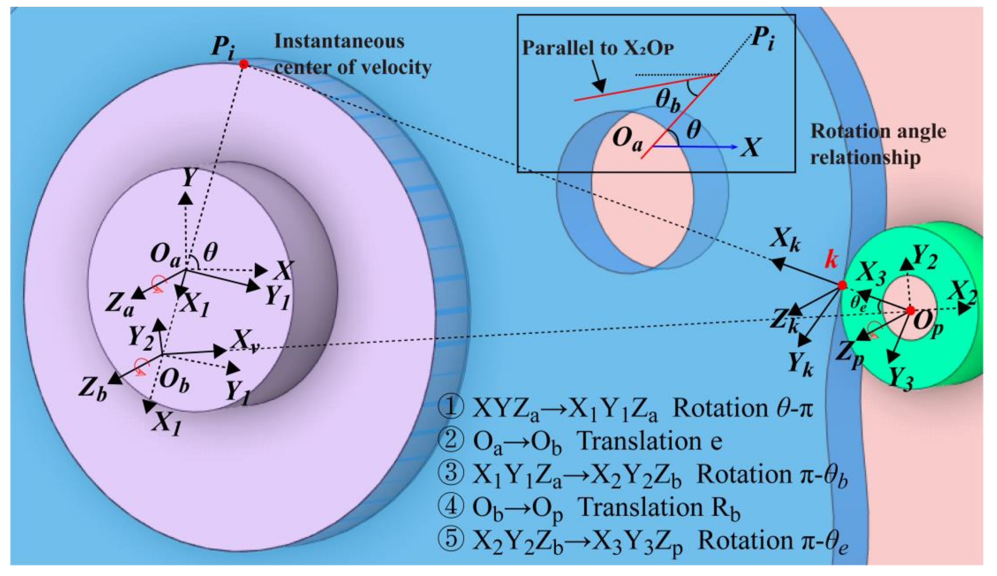
3.2. Cycloid Gear Tooth Profile Model Based on Dyadic Quaternion

In the case of fixed pin tooth, the process of profile formation of cycloid teeth can be divided into five processes as shown in Figure 3. They are rotation α = π + θ , translation e, rotation β = π θ b , translation Rb, and rotation γ = π θ e . The five processes corresponding to the dual quaternions comprise Equation (6).
P r 1 = cos α 2 , 0 , 0 , sin α 2 , 0 , 0 , 0 , 0 P t 1 = 1 , 0 , 0 , 0 , 0 , e 2 , 0 , 0 P r 2 = cos β 2 , 0 , 0 , sin β 2 , 0 , 0 , 0 , 0 P t 2 = 1 , 0 , 0 , 0 , 0 , R b 2 , 0 , 0 P r 3 = cos γ 2 , 0 , 0 , sin γ 2 , 0 , 0 , 0 , 0
where θ indicates input angle. θ b = ζ θ , ζ = z b / R b , θ e = acot R b / r b cos θ b / sin θ b .
After completing the five-step coordinate transformation process above, the coordinate of point k (rp, 0, 0) in the coordinate system X 3 Y 3 Z p is rewritten in a dual quaternion form k (1, 0, 0, 0, 0, rp, 0, 0). The cycloidal gear tooth profile equation can be obtained by multiplying as in Equation (7).
q = P r 1 P t 1 P r 2 P t 2 P r 3 p a = q * p b q
Point k in the coordinate system X 3 Y 3 Z p is expressed in the dual-quaternion space as follows:
p = 1 , 0 , 0 , 0 , 0 , r p , 0 , 0 T
After coordinate transformation, in the XYZ a coordinate system, the parameterized expression of the point k is shown in Equation (9).
x = e cos θ + R b cos θ θ b r p cos θ θ b θ e y = e cos θ + R b sin θ θ b + r p sin θ θ b θ e
The computational efficiency of this model is compared with that of the popular model in Table 1. The mean time spent on producing 100, 1000, 10,000, and 100,000 scattered points of cycloid tooth profiles with 1000 cycles as the comparison target. The results are shown in Figure 4. The new tooth profile model proposed by the authors has improved computation speed compared with other models. Specifically, the minimum improvement is 27.75801% over Model 1, and the computation time is improved by at least 3.33333% compared with Model 2. In the subsequent studies of 3D tooth profile characteristics, the new model had a significant effect when the number of scatter points increased sharply.

4. Transmission Efficiency Model

4.1. Cycloid–Pinion System Mesh Force Analysis Considering Clearance

When torque is applied, the meshing deformation of the cycloid and the pin tooth is calculated in accordance with Equation (10) [40].
δ i = φ r a sin θ i Δ e
where θ i = π θ θ e represents the angle between the normal of the i-th profile contact points and the line OaOb extension cord; φ represents the rotation angle of the cycloid subjected to torque; and Δ e represents the normal clearance, defined as the contact clearance, which leads to a change in contact force [38,41], as shown in Figure 5. The mesh force is given in Equation (11).
F i = 4 k z T [ sin θ P ( 1 sin θ ) ] / z a r a sin φ i P ( 1 sin θ ) 0
Key parameters are determined as Equation (12).
P = k k π Δ e z a Ebr b / Co A = P / ( 1 + P ) k z = π ( 1 + P ) π 2 asin A 2 A 1 A 2 1 Co = 8 T 1 v 2 ln z a r a π Ebr p 1 λ c 2 8 T 1 v 2 + 0.815
where kz indicates the coefficient of increased load in meshing due to clearances; P indicates the elastic loading parameter in meshing, which is the ratio of the initial clearance in meshing to the maximum deformation; Co and kk (kk = 1) are coefficients; v and E represent Poisson’s ratio and the elastic modulus, respectively; b represents the tooth thickness of the cycloid; and λ c represents the shortening factor of the epicycloid, λ c = r b / R b .

4.2. Cycloid–Pinion System Kinematics Analysis

Figure 6 shows the system of vectorial coordinates established by the principle of the transient center of velocity. Ipb, Icb, and Icp represent the instantaneous center of velocity. The lower corner markers p, b, and c represent the pinion, input crankshaft, and cycloid, respectively.
When the pin tooth is fixed, the instantaneous velocity center Icp of the cycloid relative to the pin tooth may be determined according to Kennedy’s theorem. In turn, the velocity of the cycloid gear relative to the pin tooth at the position of point k is obtained:
v k = w c I c p k I c p k = R b 2 + d 2 2 R b d cos θ i r p
where ω c is the rotational angular velocity of the cycloid, and I c p k is the distance between the velocity transient center I c p and the contact point k. The expression of the contact point velocity component on the coordinate axis is obtained.
θ i = 2 π z b ( i 1 ) + w in t
where w in = ( e d ) w c / e , d is the distance between the velocity instantaneous center I c p and the origin O b of the coordinate system d = z b e .

4.3. Maximum Contact Pressure

Theoretically, the contact between the cycloid and the pinion is a linear contact. As the reviewer mentions, the axes present misalignments. In actual process, the pin tooth will deflect due to the presence of the fit clearance. During the experimental observation, it is observed that the pin tooth moves along the axial direction, which is in fact due to the axial parting force. An ideal line contact would hardly lead to this phenomenon. The shift of the pin teeth leads to a reduction in the contact surface, which tends more towards the elliptical surface produced by the point contact. Therefore, in the course of the study, the authors employed a point contact rather than a line contact, as shown in Figure 7.
The maximum contact pressure Ph is
P h = 3 P / 2 π a b
where a and b denote the major and minor semi-axes of the contact ellipse, respectively. When calculating the shape parameters of the contact area, two parameters ka and kb are obtained by the second type of complete elliptic integration.
a = k a 3 w 2 E ( A + B ) 1 / 3 , b = k b 3 w 2 E ( A + B ) 1 / 3 k a = 2 E ( e ) π 1 ψ 2 1 / 3 , k b = k a 1 ψ 2
where ψ is ellipticity, ψ = 1 ( b / a ) 2 , and 0 < ψ < 1 .
The complete elliptic integrals of the first K(e) and second E(e) type are given below.
K ( e ) : = 0 π 2 d θ 1 ψ 2 sin 2 θ
E ( e ) : = 0 π 2 1 ψ 2 sin 2 θ d θ
The distance between two contact surfaces is generally expressed as s = Ax 2 + By 2 . The following relationship Equation (19) exists between A and B and the two kinds of complete elliptic integrals.
| A B | A + B = 2 1 ψ 2 ψ 2 E ( e ) K ( e ) K ( e ) + 1 = cos φ
Integrating Equations (16)–(19) and employing the dichotomy method, the solutions are obtained for the contact ellipse parameters a and b.

4.4. Cycloid–Pinion System Friction Model

Current friction coefficients are mainly based on the basic theory of tribology and empirical values derived from a large number of experiments. However, this empirical formula is predominantly case-oriented with a uniform distribution of contact loads and difficult to adapt to dynamic engagement situations. In the mesh process of the cycloid-pinion system, if the empirical value of the coefficient of friction is directly substituted for the calculation, it causes errors. Under actual operating conditions, the lubrication state of the meshing teeth is constantly changing. More specifically, the friction coefficient changes as the film thickness in the contact position changes. The time-varying coefficient of friction for mixed lubrication is calculated in the following manner.
The coefficient of mixed friction of the cycloid-pinion system is as Equation (20).
f mix = f λ 1.2 f e + 1 f λ f b
where f e and f b represent friction coefficient of full film lubrication and boundary lubrication, respectively. f λ denotes the quotient supported by the lubricant film and surface asperities. For the point contact, Zhu and Hu [42] proposed the sharing function of Equation (21). Under high-velocity and high-load operating conditions, the general value of boundary lubrication coefficient f b is 0.1 [43].
f λ = 1.21 λ 0.64 1 + 0.37 λ 1.26
where λ is the film thickness ratio.
This is based on the maximum pressure obtained according to Equation (15). Meanwhile, in previous solutions for elastohydrodynamic lubrication [44,45], the pressure is usually assumed to be Hertzian distributed and the film thickness is a constant in order to obtain an analytical solution. Muraki and Dong [46] obtained the equivalent pressure equation used to represent point contact, as shown in Equation (22). In this paper, a relatively inexpensive mineral-oil-based lubricant is selected. The corresponding effective pressure and friction coefficient are expressed as follows:
p ef = δ ln 2 δ p h 1 e n α 0 p h 1 δ p h 1 + 2 δ p h 2
f e = AW L 1 G 1 n e n α 0 p e f η 0 Δ u h min 1 n
where G the shear modulus and n is the power-law exponent with their values determined as G = 1 MPa and n = 0.5, respectively [32]; h min is the minimum film thickness; η 0 is absolute viscosity, which is set to 30 mPa·s; and the coefficient δ = 1 / n α 0 .
The following assumptions are made for a faster solution. At the moment of start-up of the cycloid–pinion system, the axis of the pinion is parallel to the direction of the axis of the cycloid. At this instant, the contact state corresponding to the minimum film thickness is still a linear contact. Oil film thickness equations are often obtained based on numerical simulations or experimental results, and these formulas have similar expressions for different materials or operating conditions. In the process of data fitting, the results of the fit are often applicable to a range of speed, load, and material parameters because of the limited number of sample data. In this paper, the minimum film thickness model proposed by Pan and Hamrock was adopted [47]. The reason for choosing this model is that the loading moment is constant during the study of this paper, corresponding to a maximum value of the load parameter of the magnitude of 1 × 10⁻⁵. According to Zhu et al. [48], in this range, the above fitted model will be in better agreement with the results obtained by the improved semi-system approach. The final result is as in Equation (24).
h min = 1.174 G * 0.568 U * 0.694 W * ( 0.128 )
with the following dimensionless material, speed, and load parameters:
G * = α E e ,         U * = η o U / E e R e ,         W * = W / E e R e l e
E e = E / 2 1 v 2
where W indicates the load parameter; R e is the equivalent curvature radius corresponding to the contact point; le represents the length of the contact line; U denotes the average surface speed; Ee is equivalent modulus of elasticity; and α is the viscosity–pressure coefficient, which is fixed at 10 G P 1 .

4.5. Transmission Efficiency Model

This is based on the determination of the coefficient of friction in the mixed lubricating state. Furthermore, it is possible to obtain the exact solution of the friction force of the cycloid system.
F f = f mix F
where f mix indicates the contact surface friction coefficient corresponding to the mixed lubrication condition.
The instantaneous frictional power consumption of the contact surface is as follows.
P i = f mix Fv k
where F represents the contact force between the i-th pin tooth and the cycloid. f mix is the coefficient of mixed friction corresponding to the i-th contact surface. v k is the relative motion velocity at the i-th pin contact point.
The total frictional power consumption of the cycloid and the pin tooth in the transmission process is the sum of the power consumption at all contact points.
P z = i = 1 z b f mix i F i v k i
where zb represents the number of pin teeth.
In summary, the instantaneous transmission power of the cycloid drive system is obtained as follows:
η z = 1 P z P o
where Po is the input power.
For the cycloid system, transmission efficiency is influenced by tolerances, fit clearances, collisions, and other factors. In this paper, the friction coefficient of the greased teeth is added to determine the mesh characteristics of the teeth. The objective is to compare the effect of the various structures on the transmission efficiency of the cycloid system and to guide the design process.

5. Comparison of Transmission Efficiency of Different Structures

After obtaining the transmission efficiency model, the design parameters of the cycloid gear are introduced to investigate the effect of contact characteristics on lubrication characteristics. The simulations are conducted with the data in Table 2. The load moment is the main input parameter, mainly referring to the RV-E series manufactured by Nabtesco. The allowable torque range for the different types of E series products is 196 N m to 44,100 N m, while the rated torque range is 58 N m to 14,700 N m. Therefore, 100 N m was selected as the input parameter in this range.

5.1. Tolerance Analysis of Different Structure

In the general state, the cycloid gear is in full contact with the pin teeth. However, under the action of the input torque, only half of the contact surface will be deformed to produce the contact force. In parallel, coupled with the effect of dimensional tolerances, the actual number of teeth engaged is less than half. For the cycloid pin gear system, the error distribution mainly lies in five parts: the cycloid, the input crank, the pin teeth, the pin gear, and the pinion sleeve. Due to dimensional tolerances, the cycloid gear must be turned through a certain angle to engage the pin teeth, defined as the tolerance clearance. To make up the tolerance clearance, the crankshaft and the cycloid gear are adapted to the assembly dimensional chain, and the pin tooth and pin gear or pinion sleeve fit assembly dimensional chain are established, respectively. Finally, the result of the solution is entered in the equation of the tooth profile to obtain the tolerance difference.
Figure 8 shows the clearance at the part joints in relation to the number of teeth meshed. The matrix with a pitch of 0.5 and overall dimensions of 61 × 61 can be obtained. When the clearance between the cycloid and the input crankshaft as well as the pin tooth is in the interval [0 μm,11 μm] in the main diagonal, a contact tooth number of 11 is the ideal meshing condition. In the XY-plane of Figure 8, it is observed that the number of contact teeth is more sensitive to the contact clearance between the housing and the pin tooth or the sleeve. The optimal area (i.e., red part) is shifted in the upper triangle of the matrix. In view of the economy of machining and assembly, the target optimal solution is set in the area around the point (26.5, 24.5, 9).
The fit is first determined for the position of the relatively insensitive connection, i.e., the input crankshaft is connected to the cycloid. The basic dimension of the center circle diameter of the cycloid gear is 144 mm. The base–hole system is selected with a clearance fit, and a maximum clearance of 26.5 μm and a minimum clearance of 0 μm are adopted as design targets. Considering the economy of machining and assembly, H3/h5 is finally chosen. The upper deviation es and lower deviation ei of the hole are 8 μm and 0 μm, respectively; the upper deviation es and lower deviation ei of the shaft are 0 μm and −18 μm, respectively. The maximum clearance of the final design is 26 μm and the minimum clearance is 0 μm.
After selecting a clearance value of 26 μm for this region, the maximum assembly clearance of the pin tooth is 24 μm according to the calculation results corresponding to Figure 8. This ensures that the number of teeth engaged is 9 and that a stable power transmission is maintained. The hole where the pin tooth is placed in the housing is reamed and machined to an accuracy of IT5, which corresponds to the diameter of φ 20 0 + 0.009 mm. The accuracy of the corresponding shaft is slightly lower; so, IT6 is adopted here, which corresponds to the diameter of φ 20 0.013 0 mm (based on the standard ISO 286). A 0 is the clearance between the crankshaft and the inner bore of the cycloid gear. Assembly dimensional chain information is shown in Table 3. In the cycloid system, the cylindrical surface of the pin tooth is a clearance fit to the pin gear, as in Figure 9. B0 is the solution target.
In the case of cycloid pin gear systems with pinion sleeve construction, the pinion sleeve has a clearance fit with the pin gear as shown in Figure 10. Similarly, the maximum clearance between the cycloid and the input crank is 26 μm. Taking this value as a reference base, the recommended maximum engagement clearance at the pin teeth is 24 μm. With this as the design objective, a clearance fit was employed. The recommended fit was obtained as H7/h6. The upper tolerances of the hole and shaft are ES = 15 μm and es = 0 μm, respectively. Meanwhile, the corresponding lower tolerances are EI = 0 μm and ei = −9 μm. The machining precision required for direct contact between the housing and the pin tooth is very high. In comparison, the machining economy of the pin tooth and the sleeve is significantly improved. To summarize, the information of each dimensional chain is shown in Table 3.
The clearance between the crankshaft and the cycloid is 26 μm by the extreme value method, i.e., A 0 = Δ R b = 26   μ m . Similarly, the clearance between the pin tooth and the pin gear, and the clearance between the pin tooth and the pinion sleeve are 22 μm and 24 μm, respectively, i.e., B 0 = Δ r p 1 = 22   μ m and C 0 = Δ r p 2 = 24   μ m . The results of the clearance calculation are carried into the tooth profile Equation (31).
x p = e cos ( α ) + R b cos ( α + β ) + r p cos ( α + β + γ ) y p = e cos ( α ) + R b sin ( α + β ) + r p sin ( α + β + γ )
The clearance variance caused by the tolerance can be calculated:
d i = min x c x p ( i ) 2 + y c y p ( i ) 2 r p
where x c and y c represent the coordinates of the discrete points of the cycloidal gear tooth profile. x p i and y p i represent the center coordinates of the i-th pin tooth, the calculation result is shown as follows:
x p ( i ) = R b sin θ i y p ( i ) = R b cos θ i i = 1 , 2 z b θ i = 2 π ( i 1 ) / z b
The addition of the sleeve visually causes a change in the meshing clearance. As shown in Figure 11, the clearance is overall symmetrically distributed. Overall, considering the economy of processing and manufacturing, the assembly dimensional chain clearance of the pin tooth sleeve housing is 2 μm larger than that of the pin tooth housing. Thus, the clearance difference between the two displays a similarly periodically varying step function.

5.2. Transmission Efficiency Comparison

The presence of the pinion sleeve affects the location of the sliding friction. Specifically, without the pinion sleeve, the main manifestation is the sliding friction between the cycloid gear and the pin tooth. When there is one pinion sleeve, it becomes the sliding friction between the pin tooth and the pin tooth sleeve. In summary, dx 1 represents the movement of friction work when there is no pinion sleeve, i.e., the relative displacement of the cycloid and pin tooth. Additionally, dx 2 indicates the movement of the work performed by the frictional force in the presence of the pinion sleeve. By taking the derivative of the two with respect to time, the corresponding velocity ratio may equal the radius ratio of the pinion sleeve to the pin tooth.
dx 1 dx 2 = v p 1 v p 2 = R tp R rp
where R tp and R rp are the radii of the pinion sleeve and the pin tooth, respectively.
The addition of a pin tooth sleeve affects the distribution of friction in the cycloid system. Inputs such as the equivalent radius of curvature and contact point velocity will also change at this point. The result will be a different mixed friction coefficient. The specific situation is shown in Figure 12. In the case of the two structures with and without pin tooth sleeves, the corresponding mixed friction coefficients of the two have a similar variation pattern at the initial moment. After considering the assembly error, the number of simultaneously meshing teeth is reduced to seven pairs for the structure without sleeve. Further, for the structure with sleeve, the number is one more pair. When t = 200 ms, the number of extra meshing teeth is two. Besides, the fluctuations of the non-zero values of the two were analyzed with the standard deviation (STD). Figure 12 shows that the pin tooth sleeve structure allows for less fluctuation in the friction coefficient of the entire system. The overall force on the cycloid is smoother.
The average power consumption and transmission efficiency for two moments (t = 0 ms and t = 10 ms) are shown in Figure 13. In the instant of starting, the direct contact power consumption between pin tooth and cycloid gear is 72.3321 W and the transmission efficiency is 99.9%, whereas after replacing the structure of pin tooth sleeve, the power consumption reduced to 27.2156 W, and the transmission efficiency increased to 99.96%. As t = 10 ms, the power consumption reduced from 35.9208 W to 16.9709 W, and the transmission efficiency improved by 0.03%.
The above experiments only illustrate the transient transmission characteristics at two different moments. Afterwards, the power consumption characteristics corresponding to the different structures will be analyzed from a continuous time period. As in Figure 14, the power loss curves corresponding to both structures oscillate up and down periodically. The curve in red, which is the structure containing the pin tooth sleeve, always remains at a lower level. Further, the box shows the variation of the first-order derivatives of the two curves, and it can be seen that the red curve has a smaller amplitude of variation. The corresponding system power transmission is more stable.
After exploring the transmission characteristics of different structures over the same settings, the variable parameters, i.e., speed as well as surface roughness, are introduced. Figure 15 shows the variation of the average efficiency for different input speeds. The rotational speed was set to 10 r/s, 20 r/s, 30 r/s, and 40 r/s. The transmission efficiency decreased from 99.97% to 99.84% as the speed increased without the pin tooth sleeve. At the same time, the power dissipation increased from 23.6 W to 119 W, while the corresponding drive efficiency remained relatively stable with a maximum decrease of 0.05% and a maximum power dissipation of 47.9 W by utilizing the pin tooth sleeve structure.
A side-by-side comparison of the data in the same row of Table 4 shows that, for the same surface quality, the improvement of the structure can improve its transmission performance. However, comparing the results longitudinally, it can be seen that for the same structure, the surface quality has a negligible effect on its transmission performance.

5.3. Structural Dynamic Simulation

For further investigation of the effect of different structural designs on the system, dynamics simulation of the cycloid system was performed with ADAMS. The static friction coefficient was uniformly set to 0.3, while the dynamic friction coefficient was 0.1. Within 0.5 s, 100 steps were set. The corresponding model is shown in Figure 16.
The structure not utilizing the pin tooth sleeve is the red line in Figure 17. There are three obvious peaks, corresponding to 5492 N, 4077 N, and 2565 N. The addition of the pinion sleeve makes the overall transmission force much smoother according to the first-order derivative of Figure 18. There is no obvious bump. The addition of the pin tooth sleeve can improve the transmission performance of the system.

6. Conclusions

In this work, on the basis of considering the assembly dimensional chain, the transmission efficiency of the two structures with and without the pinion sleeve is analyzed. Specifically, the following five aspects are included:
A more concise and accurate model of the cycloid tooth profile is proposed. Specifically, the slightest improvement over the inversion model is 27.75801%. The computation time is at least 3.33333% better than the velocity instantaneous center method model.
The variation pattern of the number of teeth engaged under the coupling effect of the assembly and meshing clearance is obtained. The target optimal solution is set in the area around the point (26.5, 24.5, 9) in Figure 7.
The way in which the different parts fit together and the corresponding upper and lower tolerances are determined to obtain a dimensional tolerance chain. Based on the extreme value method, the fit clearances of the two different structures are determined. The difference between the two shows a similar periodically varying step function.
The structure with a pin tooth sleeve corresponds to a smoother change in the coefficient of friction, indicating smoother operation of the whole system. In the same time interval, the friction without the pin tooth sleeve dissipates more power and fluctuates more sharply. The increase in input speed increases the frictional losses. However, the addition of a pin tooth sleeve can slow down the increase in losses. Within the normal range of machined surface quality, roughness has a small effect on the loss of friction efficiency.
The results of the variation of the contact forces for the two structures are obtained by ADAMS. The addition of the pin tooth sleeve makes the whole system run more smoothly.

Author Contributions

Conceptualization, N.J., S.W., and J.Z.; methodology, N.J. and J.Z.; software, N.J. and A.Y.; validation, N.J. and W.Z.; formal analysis, N.J.; investigation, N.J.; resources, N.J.; data curation, N.J.; writing—original draft preparation, N.J. and J.Z.; writing—review and editing, N.J.; visualization, N.J. and S.W.; supervision, J.Z.; project administration, S.W. All authors have read and agreed to the published version of the manuscript.

Funding

The work was funded in part by Hubei Province Technology Innovation Special Fund (No. 2019AAA069).

Institutional Review Board Statement

Not applicable.

Informed Consent Statement

Informed consent was obtained from all subjects involved in the study.

Data Availability Statement

Not applicable.

Conflicts of Interest

The authors declare no conflict of interest.

Nomenclature

ε Dual unit with the property
q, q*Dual quaternion and its conjugate
p ,   p Quaternion information before and after the transformation
p r ,   p t Unit quaternion of rotation and a translation vector
α ,   β ,   γ Coordinate transformation rotation angle
OaCenter of the cycloid gear center circle
ObCenter of the pin tooth center circle
raRadius of cycloid gear pitch circle
rbRadius of pin tooth pitch circle
eEccentricity
RbRadius of the distribution circle of the pin teeth
rpRadius of the pin tooth
θ Input angle
zaNumber of cycloid teeth
zbNumber of pin teeth
ζ Ratio of the number of cycloid teeth to the radius of pin tooth pitch circle
P, PhElastic loading and maximum contact pressure
kzCoefficient of increased load in meshing due to clearances
ω c ,   ω in Angular velocity of the cycloid and input angular velocity
a, bMajor and minor semi-axes of the contact ellipse
U*Dimensionless speed parameter
W*Dimensionless load parameter
G*Dimensionless materials parameter
f mix ,   f e ,   f b Friction coefficient of mixed lubrication, full film lubrication and boundary lubrication
η 0 Viscosity at ambient pressure
α 0 Pressure–viscosity exponent

References

  1. Sensinger, J.W.; Lipsey, J.H. Cycloid vs. Harmonic Drives for use in High Ratio, Single Stage Robotic Transmissions. In Proceedings of the 2012 IEEE International Conference on Robotics and Automation (Icra), Saint Paul, MN, USA, 14–18 May 2012; pp. 4130–4135. [Google Scholar]
  2. Maccioni, L.; Borgianni, Y.; Concli, F. High Power Density Speed Reducers: A TRIZ Based Classification of Mechanical Solutions. In Systematic Complex Problem Solving in the Age of Digitalization and Open Innovation; Cavallucci, D., Brad, S., Livotov, P., Eds.; Springer International Publishing: Cham, Switzerland, 2020; pp. 243–253. [Google Scholar]
  3. García, P.L.; Crispel, S.; Saerens, E.; Verstraten, T.; Lefeber, D. Compact Gearboxes for Modern Robotics: A Review. Front. Robot. AI 2020, 7, 103. [Google Scholar] [CrossRef] [PubMed]
  4. Yamato, H.; Ogihara, K.; Kodachi, T.; Irie, K.; Hara, Y.; Toda, K.; Okumura, Y.; Yoshida, T.; Shimizu, M.; Tomono, M.; et al. A Partner Robot Transforming to a Vehicle: CanguRo—Design, Development and Evaluation of Its In-Wheel Drive Unit with Cycloid Gear. In Proceedings of the 2020 IEEE/SICE International Symposium on System Integration (SII), Honolulu, HI, USA, 12–15 January 2020; pp. 1205–1211. [Google Scholar] [CrossRef]
  5. Tsai, Y.T.; Lin, K.H. Dynamic Analysis and Reliability Evaluation for an Eccentric Speed Reducer Based on Fem. J. Mech. 2020, 36, 395–403. [Google Scholar] [CrossRef]
  6. Wang, C.; Mao, K. Design of high power density for RV reducer. J. Braz. Soc. Mech. Sci. Eng. 2021, 43, 291. [Google Scholar] [CrossRef]
  7. Pabiszczak, S.; Kowal, M. Efficiency of the eccentric rolling transmission. Mech. Mach. Theory 2021, 169, 104655. [Google Scholar] [CrossRef]
  8. Yang, M.; Zhang, D.; Cheng, C.; Han, X. Reliability-based design optimization for RV reducer with experimental constraint. Struct. Multidiscip. Optim. 2021, 63, 2047–2064. [Google Scholar] [CrossRef]
  9. Matejic, M.; Goluza, V.; Vasic, M.; Blagojevic, M. Analysis of Two-Stage Cycloid Speed Reducers Dimensions and Efficiency. In International Conference on Machine and Industrial Design in Mechanical Engineering; Springer: Cham, Switzerland, 2022; pp. 171–181. [Google Scholar] [CrossRef]
  10. Lin, K.-S.; Chan, K.-Y.; Lee, J.-J. Kinematic error analysis and tolerance allocation of cycloidal gear reducers. Mech. Mach. Theory 2018, 124, 73–91. [Google Scholar] [CrossRef]
  11. Wang, H.; Shi, Z.-Y.; Yu, B.; Xu, H. Transmission Performance Analysis of RV Reducers Influenced by Profile Modification and Load. Appl. Sci. 2019, 9, 4099. [Google Scholar] [CrossRef] [Green Version]
  12. Tung, L.-C.; Chan, Y.J. A time-variant dynamic model for compound epicyclic–cycloidal reducers. Mech. Mach. Theory 2023, 179, 105095. [Google Scholar] [CrossRef]
  13. Li, X.; Zhang, Y. Meshing characteristic analysis of a cycloid drive with epitrochoid profile and its conjugate envelope. Forsch. Im Ing. 2020, 84, 333–343. [Google Scholar] [CrossRef]
  14. Jin, S.-S.; Tong, X.-T.; Wang, Y.-L. Influencing Factors on Rotate Vector Reducer Dynamic Transmission Error. Int. J. Autom. Technol. 2019, 13, 545–556. [Google Scholar] [CrossRef]
  15. Yang, R.; Li, F.; Zhou, Y.; Xiang, J. Nonlinear dynamic analysis of a cycloidal ball planetary transmission considering tooth undercutting. Mech. Mach. Theory 2019, 145, 103694. [Google Scholar] [CrossRef]
  16. Zhang, Z.; Wang, J.; Zhou, G.; Pei, X. Analysis of mixed lubrication of RV reducer turning arm roller bearing. Ind. Lubr. Tribol. 2018, 70, 161–171. [Google Scholar] [CrossRef]
  17. Sensinger, J.W. Unified Approach to Cycloid Drive Profile, Stress, and Efficiency Optimization. J. Mech. Des. 2010, 132, 024503. [Google Scholar] [CrossRef]
  18. Malhotra, S.; Parameswaran, M. Analysis of a cycloid speed reducer. Mech. Mach. Theory 1983, 18, 491–499. [Google Scholar] [CrossRef]
  19. Gorla, C.; Davoli, P.; Rosa, F.; Longoni, C.; Chiozzi, F.; Samarani, A. Theoretical and Experimental Analysis of a Cycloidal Speed Reducer. J. Mech. Des. 2008, 130, 112604. [Google Scholar] [CrossRef]
  20. Matejic, M.; Blagojevic, M.; Cofaru, I.I.; Kostic, N.; Petrovic, N.; Marjanovic, N. Determining efficiency of cycloid reducers using different calculation methods. In MATEC Web of Conferences; EDP Sciences: Les Ulis, France, 2019; Volume 290, p. 01008. [Google Scholar] [CrossRef] [Green Version]
  21. Lin, W.-S.; Shih, Y.-P.; Lee, J.-J. Design of a two-stage cycloidal gear reducer with tooth modifications. Mech. Mach. Theory 2014, 79, 184–197. [Google Scholar] [CrossRef]
  22. Chen, B.K.; Fang, T.T.; Li, C.Y.; Wang, S.Y. Gear geometry of cycloid drives. Sci. China Ser. E-Technol. Sci. 2008, 51, 598–610. [Google Scholar] [CrossRef]
  23. Hsieh, C.-F. Traditional versus improved designs for cycloidal speed reducers with a small tooth difference: The effect on dynamics. Mech. Mach. Theory 2015, 86, 15–35. [Google Scholar] [CrossRef]
  24. Concli, F.; Maccioni, L.; Gorla, C. Lubrication of gearboxes: CFD analysis of a cycloidal gear set. WIT Trans. Eng. Sci. 2019, 123, 101–112. [Google Scholar] [CrossRef] [Green Version]
  25. Wei, B.; Wang, J.; Zhou, G.; Yang, R.; Zhou, H.; He, T. Mixed lubrication analysis of modified cycloidal gear used in the RV reducer. Proc. Inst. Mech. Eng. Part J-J. Eng. Tribol. 2016, 230, 121–134. [Google Scholar]
  26. Sun, Z.; Zhu, C.; Liu, H.; Song, C.; Gu, Z. Study on Starved Lubrication Performance of a Cycloid Drive. Tribol. Trans. 2016, 59, 1005–1015. [Google Scholar] [CrossRef]
  27. Zhu, C.C.; Sun, Z.D.; Liu, H.J.; Song, C.S.; Gu, Z.L. Effect of tooth profile modification on lubrication performance of a cycloid drive. Proc. Inst. Mech. Eng. Part J-J. Eng. Tribol. 2015, 229, 785–794. [Google Scholar] [CrossRef]
  28. Bednarczyk, S. Analysis of the cycloidal reducer output mechanism while taking into account machining deviations. Proc. Inst. Mech. Eng. Part C-J. Mech. Eng. Sci. 2021, 235, 7299–7313. [Google Scholar] [CrossRef]
  29. Tran, T.L.; Pham, A.D.; Ahn, H.-J. Lost motion analysis of one stage cycloid reducer considering tolerances. Int. J. Precis. Eng. Manuf. 2016, 17, 1009–1016. [Google Scholar] [CrossRef]
  30. Wang, Y.; Qian, Q.; Chen, G.; Jin, S.; Chen, Y. Multi-objective optimization design of cycloid pin gear planetary reducer. Adv. Mech. Eng. 2017, 9, 1–10. [Google Scholar] [CrossRef]
  31. Ono, H. Tribology of Machining. J. Jpn. Soc. Technol. Plast. 2017, 58, 656–660. [Google Scholar] [CrossRef]
  32. Otero, J.E.; Morgado, P.L.; Tanarro, E.C.; Ochoa, E.D.L.G.; Lantada, A.D.; Guijosa, J.M.M.; Sanz, J.L.M. Analytical model for predicting the friction coefficient in point contacts with thermal elastohydrodynamic lubrication. Proc. Inst. Mech. Eng. Part J-J. Eng. Tribol. 2011, 225, 181–191. [Google Scholar] [CrossRef]
  33. Jackson, M.J.; Whitfield, M.; Robinson, G.M.; Morrell, J.; Davim, J.P. Tribology of Machining. In Tribology in Manufacturing Technology; Davim, J.P., Ed.; Springer: Berlin/Heidelberg, Germany, 2013; pp. 67–101. [Google Scholar]
  34. Wang, R.; Gao, F.; Lu, M.; Liu, T. Meshing Efficiency Analysis of Modified Cycloidal Gear Used in the RV Reducer. Tribol. Trans. 2019, 62, 337–349. [Google Scholar] [CrossRef]
  35. Li, T.; An, X.; Deng, X.; Li, J.; Li, Y. A New Tooth Profile Modification Method of Cycloidal Gears in Precision Reducers for Robots. Appl. Sci. 2020, 10, 1266. [Google Scholar] [CrossRef] [Green Version]
  36. Wu, K.-Y.; Shih, Y.-P.; Lee, J.-J. Kinematic error analysis of the rotor vector gear reducer with machining tolerances. J. Braz. Soc. Mech. Sci. Eng. 2020, 42, 566. [Google Scholar] [CrossRef]
  37. Li, X.; Chen, B.-K.; Wang, Y.-W.; Lim, T.C. Mesh stiffness calculation of cycloid-pin gear pair with tooth profile modification and eccentricity error. J. Central South Univ. 2018, 25, 1717–1731. [Google Scholar] [CrossRef]
  38. Tchufistov, E.A.; Tchufistov, O.E. Simulation of satellite bearings loading in planetary cycloid gear. In Proceedings of the International Conference on Modern Trends in Manufacturing Technologies and Equipment (Icmtmte) 2020, Sevastopol, Russia, 7–11 September 2020; p. 971. [Google Scholar]
  39. Shin, J.-H.; Kwon, S.-M. On the lobe profile design in a cycloid reducer using instant velocity center. Mech. Mach. Theory 2006, 41, 596–616. [Google Scholar] [CrossRef]
  40. Kostić, N.; Blagojević, M.; Petrović, N.; Matejić, M.; Marjanović, N. Determination of Real Clearances Between Cycloidal Speed Reducer Elements by the Application of Heuristic Optimization. Trans. Famena 2018, 42, 15–26. [Google Scholar] [CrossRef] [Green Version]
  41. Artyomov, I.I.; Tchufistov, E.A.; Tchufistov, O.E. Stress loading and losses of power in the pin-roller gearing with clearances. IOP Conf. Series Mater. Sci. Eng. 2019, 537, 032091. [Google Scholar] [CrossRef]
  42. Zhu, D.; Hu, Y.-Z. A Computer Program Package for the Prediction of EHL and Mixed Lubrication Characteristics, Friction, Subsurface Stresses and Flash Temperatures Based on Measured 3-D Surface Roughness. Tribol. Trans. 2001, 44, 383–390. [Google Scholar] [CrossRef]
  43. Sadeghi, F. 6—Elastohydrodynamic lubrication. In Tribology and Dynamics of Engine and Powertrain; Rahnejat, H., Ed.; Woodhead Publishing: Sawston, UK, 2010; pp. 171e–226e. [Google Scholar]
  44. Stachowiak, G.W.; Batchelor, A.W. Chapter 10—Fundamentals of Contact Between Solids. In Engineering Tribology, 4th ed.; Butterworth-Heinemann: Boston, MA, USA, 2014; pp. 475–524. [Google Scholar]
  45. Bair, S. Chapter Four—Compressibility and the Equation of State. In High Pressure Rheology for Quantitative Elastohydrodynamics, 2nd ed.; Bair, S., Ed.; Elsevier: Amsterdam, The Netherlands, 2019; pp. 73–95. [Google Scholar]
  46. Muraki, M.; Dong, D. Derivation of basic rheological parameters from experimental elastohydrodynamic lubrication traction curves of low-viscosity lubricants. Proc. Inst. Mech. Eng. Part J-J. Eng. Tribol. 1999, 213, 53–61. [Google Scholar] [CrossRef]
  47. Yang, D.; Blanche, J. Design and application guidelines for cycloid drives with machining tolerances. Mech. Mach. Theory 1990, 25, 487–501. [Google Scholar] [CrossRef]
  48. Wang, Q.J.; Zhu, D. Interfacial Mechanics: Theories and Methods for Contact and Lubrication; CRC Press: Boca Raton, FL, USA, 2019. [Google Scholar]
Figure 1. Thesis research framework.
Applsci 12 11917 g001
Figure 2. RV reducer structure.
Applsci 12 11917 g002
Figure 3. Cycloidal profile single-point coordinate transformation trajectory.
Applsci 12 11917 g003
Figure 4. Computational efficiency comparison.
Applsci 12 11917 g004
Figure 5. Tooth contact force considering clearance.
Applsci 12 11917 g005
Figure 6. Cycloid and pin tooth contact point (point k) velocity model.
Applsci 12 11917 g006
Figure 7. Point contact model of cycloid wheel and pin teeth.
Applsci 12 11917 g007
Figure 8. Number of teeth meshed depending on system clearance.
Applsci 12 11917 g008
Figure 9. Assembly dimension chain of the original structure.
Applsci 12 11917 g009
Figure 10. Assembly dimension chain of the improved structure.
Applsci 12 11917 g010
Figure 11. Pattern of meshing clearance distribution (w = 20 r/s, t = 0 ms).
Applsci 12 11917 g011
Figure 12. Mixed friction coefficient comparison (w = 20 r/s, Ra = 0.3 μm).
Applsci 12 11917 g012
Figure 13. Average efficiency and average power comparison. (a) t = 0 ms; (b) t = 10 ms.
Applsci 12 11917 g013
Figure 14. System power consumption within 1 s.
Applsci 12 11917 g014
Figure 15. Average efficiency vs. angular velocity (Ra = 0.3 μm). (a) Without sleeve; (b) With sleeve.
Applsci 12 11917 g015
Figure 16. Two structural simulation models. (a) Construction without pin tooth sleeve (red indicates pin teeth). (b) Construction with pin tooth sleeve (cyan indicates sleeve).
Applsci 12 11917 g016
Figure 17. Variation curve of meshing force.
Applsci 12 11917 g017
Figure 18. First-order derivative of the meshing force curve.
Applsci 12 11917 g018
Table 1. Cycloid tooth profile model for comparison.
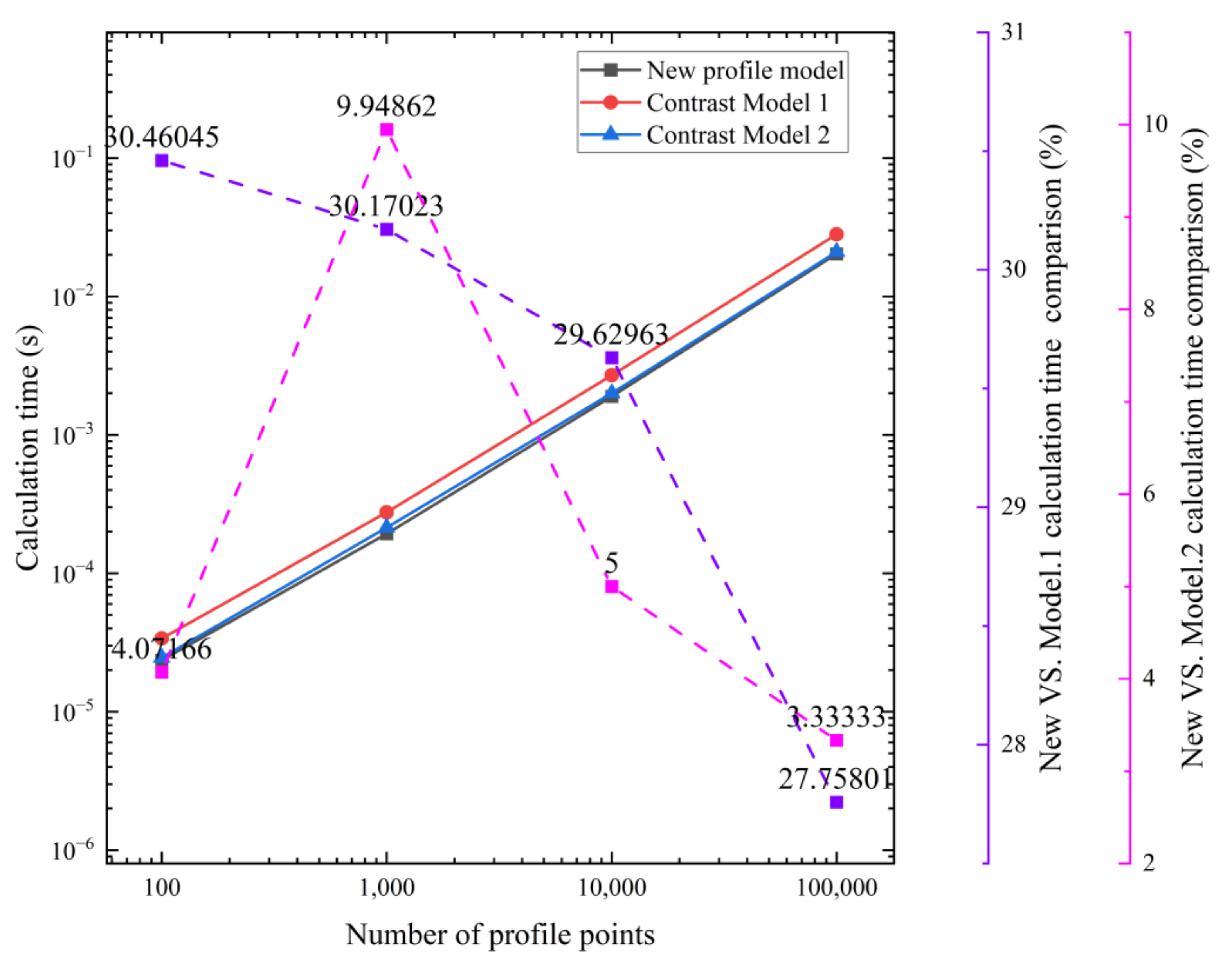
Contrast Model 1: such models are mainly derived based on the inversion method [5,11,35] x r 1 = R b r p S sin [ ( 1 ζ ) θ ] e kr p S sin ζ θ y r 1 = R b r p S cos [ ( 1 ζ ) θ ] e kr p S cos ζ θ S = 1 + k 2 2 k cos θ 1 / 2
Contrast Model 2: tooth profile model is derived based on the method of velocity transient centers [36,37,38,39] x r 2 = R b cos θ z a + r p cos θ m θ z a e cos ζ θ y r 2 = R b sin θ z a + r p sin θ m θ z a + e sin ζ θ θ m = arccot 1 [ k sin θ / ( 1 k cos θ ) ] , k = ζ e
Table 2. Cycloid design parameters.
ParameterValueParameterValue
Load torque, T (N m)100Number of cycloidal teeth, za23
Density, ρ (Kg/m3)7830Number of pin tooth, zb24
Poisson’s ratio ν 0.3Pin pitch radius, rb (mm)30
Yield limit, (MPa)518Cycloid pitch circle radius, ra (mm)27
Elastic modulus, E (GPa)208Pin radius, rp (mm)10
Transmission ratio24Eccentricity, e (mm)3
Pin center circle radius, Rb (mm)100Cycloid tooth width, b (mm)10
Table 3. Assembly dimensional chain.
LinkPartTolerance (μm)
Decreasing link A1Crankshaft diameter−18
Increasing link A2Cycloid bore diameter+8
Decreasing link B1Pin tooth diameter−13
Increasing link B2Pin gear bore diameter+9
Decreasing link C1Pin tooth diameter−9
Increasing link C2Sleeve diameter+15
Table 4. Transmission characteristics depending on roughness.
Contact Surface Roughness (μm)With SleeveWithout Sleeve
Transmission Efficiency (%)Power Consumption (W)Transmission Efficiency (%)Power Consumption (W)
0.299.9349.340399.84121.8433
0.399.9447.940999.84119.1266
0.499.9446.820299.85115.9343
0.599.9447.975799.85113.0107
Publisher’s Note: MDPI stays neutral with regard to jurisdictional claims in published maps and institutional affiliations.

