Article

Simplified Double-Integral Sliding-Mode Control of PWM DC-AC Converter with Constant Switching Frequency

by
Humam Al-Baidhani
1,2 and
Marian K. Kazimierczuk
1,*
1
Department of Electrical Engineering, Wright State University, Dayton, OH 45435, USA
2
Department of Computer Techniques Engineering, Faculty of Information Technology, Imam Ja’afar Al-Sadiq University, Baghdad 10012, Iraq
*
Author to whom correspondence should be addressed.
Appl. Sci. 2022, 12(20), 10312; https://doi.org/10.3390/app122010312
Submission received: 9 September 2022 / Revised: 3 October 2022 / Accepted: 6 October 2022 / Published: 13 October 2022
(This article belongs to the Special Issue Power Converters: Modeling, Control, and Applications II)

Abstract

:

Featured Application

Provide a robust-control design technique for pulse-width-modulated power converters in continuous conduction mode using low-cost analog circuits.

Abstract

In this paper, a simplified double-integral sliding-mode control method for pulse-width-modulated dc-ac buck conversion is introduced. The control equation is derived based on the equivalent control method, in which the control-oriented model is developed using the averaged dynamics of the power converter in continuous conduction mode. In contrast with the conventional sliding-mode control schemes, the complexity of adding a capacitor current sensor, variable ramp voltage, and other relevant components is avoided. Furthermore, the control equation is translated into a simple electronic circuit with minimal added components, which reduces the practical implementation cost. The proposed control method rejects large disturbances, tracks the reference signal, and maintains a constant switching frequency. Systematic design procedure, control parameters selection, and stability conditions are presented. The design methodology is verified via simulating the proposed control circuit using Simscape Electrical in MATLAB. The control method is also compared with the conventional double-integral sliding-mode control scheme under load disturbances. The results show that the simplified control approach provides a fast transient response and robust tracking performance.

1. Introduction

PWM power converters have been utilized in several industrial applications, such as communication systems, modern power grids, and renewable energy systems [1]. Sliding-mode control (SMC) has been studied and applied to power converters due to its fast transient response, ease of implementation, and robustness against system parameter variation. It is also considered one of the common nonlinear control techniques that is suited for variable structure systems, including power supplies [2]. However, a common issue that is associated with this control method is the steady-state error at the output voltage. This is attributed to the implementation of the SMC via a pulse-width modulator, which is utilized to obtain a constant switching frequency, minimize EMI issues, and reduce the complexity of filter design [3,4]. In other words, the derivation of the equivalent control law in the PWM-based SMC method eliminates the high and variable switching frequency issues, but it degrades the tracking performance, which results in an undesirable dc error [3].
Considerable research work has been conducted to eliminate the steady-state error using double-integral sliding-mode control (DI-SMC), which is also known as proportional–integral sliding-mode control (PI-SMC) [5,6,7,8,9,10,11,12,13,14,15,16,17,18,19,20,21,22,23,24,25,26,27,28,29,30]. The DI-SMC system has been applied to the quadratic boost converter [5], bridgeless converter [6], dual-active-bridge converter [7], four-quadrant quasi-Z-source converter [8], and MPPT of photovoltaic systems [9]. A nonlinear controller that combines backstepping and DI-SMC techniques for dc-dc boost converters has been proposed in [10]. Previous research endeavors have presented robust control design techniques, but they fall short of developing systematic design procedures that are suitable for low-cost commercial and industrial applications. In [11], a double-integral sliding surface for indirect analog SMC for dc-dc converters was introduced. However, the control scheme requires two PI compensators and an output capacitor current, which increase the control complexity and analog implementation cost. In addition, the capacitor current sensor degrades the power converter efficiency via increasing the effective series resistance (ESR) value in the capacitor branch [4].
The PI-SMC method has been proposed for boost converter [12], SEPIC converter [13], three-level converter [14], third-order super-lift Luo converter [15], fourth-order Cuk converter [16], and multiport power supply system [17]. The modified PI-SMC of hybrid boost converter [18], hybrid DI-SMC of buck converter [19], hierarchal PI-SMC of buck converter [20], and PI Hyperplane SMC of buck–boost converter [21] have been reported. Cascaded PI-SMC schemes have also been introduced for classical dc-dc boost [22] and buck–boost [23] converters. However, the detailed design procedure and analog realization of the control law were not reported. Considering digital and intelligent control methods, a digital PI-SMC using an interpolation-predictive strategy was given in [24]. Furthermore, the SMC has been incorporated with advanced techniques such as nonlinear deep reinforcement learning [25], extended state observer [26], particle swarm optimization [27], genetic algorithm [28], and fuzzy neural network [29]. The intelligent controls provide reliable methods to tune the controller gains according to the operating conditions, but the complexity of the practical implementation increases dramatically. The nonlinear control schemes in the previous endeavors also fall short of introducing robust DI-SMC methods that can be translated into analog circuits.
Analog DI-SMC circuits have been introduced in [3,10] for dc-dc converters, but the presence of double-PI compensators and an output capacitor current branch in the control scheme were unavoidable issues. In [30], a DI-SMC method with a constant switching frequency was presented using an analog circuit that does not require an output capacitor current branch. However, the control circuit contains double-PI compensators, which slow down the closed-loop system response, complicate the control circuit structure, and increase the cost of practical implementation. Motivated by the previous research, this paper aims to introduce a robust DI-SMC method with constant switching frequency for a PWM dc-ac buck converter using a simple analog circuit.
The main contributions in this research are summarized as follows: (1) A simplified DI-SMC method is proposed for a dc-ac power converter with constant switching frequency. (2) The proposed control scheme contains a single-PI compensator and does not require an output capacitor branch as conventional DI-SMC schemes do. (3) The control law derivation and the controller gains selection, along with the existence and stability conditions, are provided. (4) A detailed design procedure is introduced to realize the analog control circuit with minimal added components. (5) To validate the proposed design methodology and evaluate the tracking performance under large disturbances, the simplified DI-SMC circuit is simulated in Simscape Electrical in MATLAB and compared with a conventional DI-SMC scheme. The rest of the paper is organized as follows. The simplified DI-SMC design approach is given in Section 2. The realization of the analog control circuit is introduced in Section 3. The simulation results are presented in Section 4, and the conclusions are summarized in Section 5.

2. Simplified DI-SMC Design of DC-AC Buck Converter

The proposed control design approach includes the development of a control-oriented model, the derivation of an equivalent control law, and a controller gains selection method. A simplified DI-SMC method was reported in [31] and was applied to the classical dc-dc buck and boost converters in continuous conduction mode (CCM). In this research, the simplified nonlinear control method is extended to the PWM dc-ac buck converter that works as a dynamic power supply for radio-frequency power amplifiers (RFPAs) [32]. This type of power converter steps the dc input voltage down to a sinusoidal output voltage by varying the duty cycle from 0.1 to 0.9 and tracking a sinusoidal reference signal. The block diagram of the simplified DI-SMC scheme of the dc-ac power converter is shown in Figure 1.

2.1. Control-Oriented Model

The control-oriented model should be first developed to reflect the error dynamics of the power converter, which will be used to derive the simplified control equation based on the equivalent control method. The time-variant control-state variables x1, x2, x3, and x4 have been chosen as an output voltage error, a time derivative of output voltage error, an integral of output voltage error, and a double integral of output voltage error, respectively.
x 1 = V r β v O x 2 = x ˙ 1 x 3 = x 1 d t x 4 = x 1 d t d t
where Vr, β , and vO represent the reference voltage, output voltage sensor gain, and instantaneous output voltage, respectively. The fourth state, x4, in (1) contains a double integral term, which is added to improve the tracking performance and eliminate the steady-state error at the output voltage.
On the other hand, the ideal model of the buck converter in CCM is given by
d i L d t = 1 L v O + 1 L v I u d v O d t = 1 C i L 1 r C v O          
where r, vI, and iL represent the instantaneous load resistance, input voltage, and inductor current, respectively. The capacitor and inductor of the power converter are C and L, respectively. The switching control input, u, takes a value of 1 or 0. As reported in [31], if the ideal model of the buck converter in (2) is reflected by the control-state variables in (1), then one obtains
x 1 = V r β v O x 2 = β C i C x 3 = V r β v O d t x 4 = V r β v O d t d t  
where iC represents the instantaneous capacitor current of the power converter. Thus, the time derivatives of the control-state variables in (3) yield the following dynamics:
x ˙ 1 = β C i C x ˙ 2 = β r C 2 i C β v I L C u + β v O L C   x ˙ 3 = V r β v O x ˙ 4 = V r β v O d t
Hence, the averaged control-oriented model of the power converter is obtained via averaging (4), according to [4], and gives
x ¯ ˙ 1 = β C i ¯ C x ¯ ˙ 2 = β r ¯ C 2 i ¯ C β v ¯ I L C u e + β v ¯ O L C   x ¯ ˙ 3 = V r β v ¯ O x ¯ ˙ 4 = V r β v ¯ O d t .
The terms i ¯ C , r ¯ , v ¯ I , u e , and v ¯ O represent the averaged quantities of the capacitor current, load resistance, input voltage, control input, and output voltage, respectively. The averaged control-oriented model in (5) is the key to simplifying the equivalent control equation and the corresponding analog control circuit.

2.2. Equivalent Control Law

According to [3], if the hysteresis-modulation-based SMC method is utilized with the power converters, a variable switching frequency is generated, which complicates the design of the filters and worsens the EMI issues [3]. Hence, the equivalent control method should be applied to the PWM-based SMC design to maintain a constant switching frequency.
To derive the equivalent control law, the hitting condition must be satisfied [3]. This condition can be achieved by choosing a suitable switching control law, which can be defined as
u = 1               for   ψ > 0 0               for   ψ < 0
where ψ is the sliding surface, which is given by
ψ = α 1 x 1 + α 2 x 2 + α 3 x 3 + α 4 x 4 .
The parameters α 1 , α 2 , α 3 , and α 4 in (7) are positive constants that represent the sliding coefficients.
The direct implementation of the switching control law, u, in (6) with a pulse-width modulator is not possible [3]. Instead, an equivalent control law, ue, should be derived and mapped onto a duty cycle, d. Now, if (7) is derived with respect to time, then one obtains the following sliding surface dynamics:
ψ ˙ = α 1 x ˙ 1 + α 2 x ˙ 2 + α 3 x ˙ 3 + α 4 x ˙ 4 = 0 .
It should be noticed that (8) is equated to zero based on the invariance conditions presented in [4], which means that the dynamics of the control-state variables become zero at the sliding surface, ψ , if a proper control input is applied to the power converter. Next, the averaged model in (5) is substituted into (8), yielding
α 1 β C i ¯ C + α 2 β r ¯ C 2 i ¯ C β v ¯ I L C u e + β v ¯ O L C + α 3 V r β v ¯ O + α 4 V r β v ¯ O d t = 0 .
It is known that the averaged capacitor current, i ¯ C , at a steady state is zero [4]. Hence, if the terms i ¯ C in (9) are neglected, then one obtains
α 2 β v ¯ I L C u e + β v ¯ O L C + α 3 V r β v ¯ O + α 4 V r β v ¯ O d t = 0 .
Now, solving for the equivalent control law, ue, we obtain
u e = K p V r β v ¯ O β v ¯ I + K i V r β v ¯ O d t β v ¯ I + v ¯ O v ¯ I .
The controller parameters Kp and Ki represent the proportional and integral gains, respectively, which are given by
K p K i T = L C α 3 α 2 L C α 4 α 2 T
In [3,4], the equivalent control law, ue, is related to the duty cycle, d, and the peak ramp voltage, VT, by the following relationship: 0 < d = u ^ e V T < 1 . This maps (11) onto the following control equation:
  u ^ e = γ K p V r β v ¯ O + K i V r β v ¯ O d t + β v ¯ O V T = γ β v ¯ I
Note that the control voltage, u ^ e , divided by the peak ramp voltage, V T , gives the duty cycle, d, which varies between 0 and 1.
In (13), parameter γ is a scaling factor (0 < γ < 1), which can be utilized to scale the parameters of the control equation down within the practical range of the analog control circuit. For instance, if V T = β v ¯ I is 10 V and the maximum ramp voltage of the pulse-width modulator, IC, is 5 V, then V T is multiplied by a scaling factor of 0.5. The same factor should also be used to scale down control equation u ^ e to maintain a consistent relationship among u ^ e , V T , and d.

2.3. Existence and Stability Conditions

The existence and stability conditions must be derived to ensure a proper selection for the controller gains that satisfy the SMC operation [3]. The local reachability condition is applied to derive the existence condition lim ψ 0 ψ ψ ˙ < 0 , which can be expressed as
    K p x 1 m a x + K i x 3 m a x < β v I m i n v O K p x 1 m i n K i x 3 m i n < β v O .
The minimum and maximum quantities of v I , x 1 , and x 3 are included in (14) to take the full-load operating conditions into account. This condition ensures that all the trajectories remain within the vicinity of the sliding surface [31].
In order to analyze the stability of the closed-loop dynamics of the power converter around the desired equilibrium point, the linearization of the nonlinear dc-ac buck converter model is required. The averaged closed-loop power converter dynamics are
d i ¯ L d t = 1 L v ¯ O + 1 L v ¯ I u e d v ¯ O d t = 1 C i ¯ L 1 r ¯ C v ¯ O
where u e is the equivalent control law given in (11). The linearized model of the power converter is obtained by perturbing (15) around the equilibrium point IL = VO/R, which results in
x ˜ ˙ 1 x ˜ ˙ 2 x ˜ ˙ 3 = 0 j 12 j 13 j 21 j 22 0 0 1 0 x ˜ 1 x ˜ 2 x ˜ 3 .
The states of the linearized model x ˜ 1 , x ˜ 2 , and x ˜ 3 are defined as i ˜ L , v ˜ O , and v ˜ O d t , respectively. The Jacobian Matrix J in (16) is defined by
J = 0 K p L K i L 1 C 1 R C 0 0 1 0 .
It should be noted that the linearized model in (16) is obtained considering that v I = V I , r = R , V r β V O = 0 , I L > i ˜ L , and V O >   v ˜ O . The characteristic equation of the linearized model is given by
λ j 12 j 13 j 21 λ j 22 0 0 1 λ = λ 3 + P 1 λ 2 + P 2 λ + P 3 = 0
where the parameters P 1 , P 2 , and P 3 are defined as
P 1 P 2 P 3 T = j 22 j 12 j 21 j 13 j 21 T
The linearized closed-loop power converter model is stable if all the Eigen values of the Jacobian Matrix have a negative real part. Using the Routh–Hurwitz stability criterion, one obtains the following stability conditions P 1 > 0 , P 3 > 0 , and P 2 > P 3 P 1 .
The existence and stability conditions ensure that the controller gains K p and K i in the equivalent control equation, maintain the control-state variables within the vicinity of the sliding surface, and drive them toward the desired equilibrium point.

3. Design of Analog Control Circuit

The design procedure of the simplified analog control circuit is introduced in this subsection. The proposed control circuit is depicted in Figure 2, and the parameters of the dynamic buck converter are given in Table 1 [32]. An input filter capacitor Ci of 470 μF and 0.2 Ω ESR is added to the power converter input to accommodate the discontinuous input current. The feedback network gain, β , is assumed to be 5/14. Based on the existence and stability conditions, the proportional and integral gains Kp and Ki are set to 27.6 and 13.8 × 10⁴, respectively. In addition, a scaling factor, γ, of 0.4 is selected to scale down the control parameters values and fit the practical range. General-purpose op-amps such as LF356 [4] and LM318 [3] can be used to construct the analog control circuit.
The design steps of the simplified control circuit components can be summarized as follows:
  • Output voltage sensor: The feedback network gain, β , is set to 5/14, and β = RB/(RA + RB), where RA and RB are the resistors of the output voltage sensor. If the value of RA is assumed to be 9.1 kΩ, then RB is 5.1 kΩ.
  • Summing amplifier: The resistors RS1, RS2, and RS3 for the summing op-amp can be set to 5.1 kΩ.
  • PWM generator: Since the input voltage, VI, is 28 V, the ramp voltage of the pulse-width modulator VT = β VI = 10 V, and the switching frequency fs is set to 1 MHz.
  • Scaling factor: If a scaling factor, γ, is required to scale down VT to 4 V, then γ can be set to 0.4 = RI1/RI2. Hence, if RI2 is chosen as 5.1 kΩ, then RI1 is 2 kΩ.
  • Proportional gain Kp: According to [33], the proportional gain is defined as Kp = R2/R1. Thus, if the value of Kp is 27.6 and R1 is selected as 33 kΩ, then R2 becomes 910 kΩ.
  • Integral gain Ki: In [33], the integral gain is defined as Ki = 1/(R1 C). If the value of Ki is set to 13.8 × 10⁴ and R1 is 33 kΩ, then C can be chosen as 220 pF.
It should be noted that the sum of the feedback resistors RA and RB must be greater than the maximum load resistor to reduce the loading effect of the feedback network [33]. High-precision feedback resistors should be selected to obtain an accurate output voltage measurement. It is also worth noting that the values of the gains Kp and Ki given in this research are not unique. Different values can be chosen within the practical range if they satisfy the existence and stability conditions [31]. The proposed control equation in (13), along with the selected control parameters, can be written as
  u ^ e = 0.4 27.6 V r β v ¯ O + 13.8 × 10 4 V r β v ¯ O d t + β v ¯ O V T = 4   V ,
and the corresponding analog control circuit is given in Figure 2.

4. Results and Discussion

4.1. Steady-State Performance

The simplified double-integral sliding-mode-controlled PWM dc-ac buck converter circuit was built and simulated in MATLAB using Simscape Electrical. Figure 3 shows the Simscape Electrical model of the closed-loop dynamic buck converter using MATLAB, in which all the electrical elements are defined. As shown in Figure 3, the simplified control circuit is made up of three op-amps with seven resistors and a capacitor. The sinusoidal reference signal is generated using the MATLAB function that varies the reference waveform between 3 V and 23 V at 100 Hz. The pulse-width modulator is constructed using the MATLAB function that compares the control signal with a ramp waveform.
MATLAB simulation result in Figure 4 shows the steady-state waveforms of the input voltage, vI, output voltage, vO, reference voltage, vR, and inductor current, iL. The ramp voltage, VT, switching frequency, fs, input voltage, VI, and load resistance, R, of the electrical model of the closed-loop power converter are set to 4 V, 1 MHz, 28 V, and 75 Ω, respectively. It can be noticed that the closed-loop power converter converts 28 VDC input voltage to (3–23) VAC sinusoidal output voltage at 100 Hz. In addition, the operation of the power converter is maintained in continuous conduction mode, as shown in the inductor current waveform. The simulation result also shows the accurate tracking performance of the proposed control circuit.

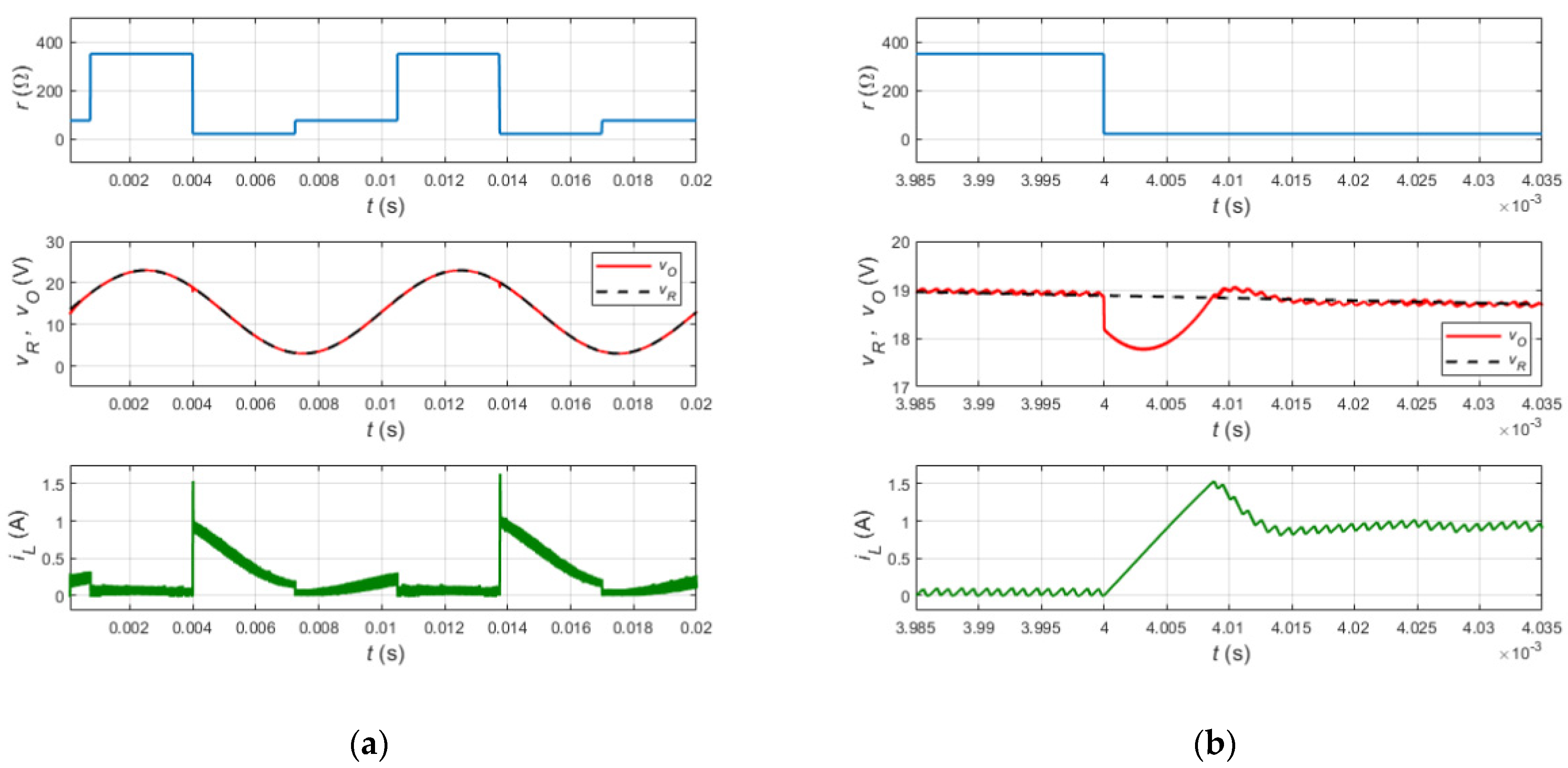
4.2. Tracking Performance under Large-Load Disturbance

The output voltage response of the closed-loop power converter during abrupt changes in load resistance is depicted in Figure 5. As shown in Figure 5a, the load profile changes abruptly from 75 Ω to 350 Ω, 20 Ω, and then returns to 75 Ω. It can be seen that the output voltage, vO, tracks the reference signal, vR, accurately and rejects the load disturbances. Figure 5b shows an enlarged view of the closed-loop power converter response when the load changes from 350 Ω to 20 Ω at t = 4 ms. The output voltage, vO, exhibits a percentage undershoot of 5.8% and then returns to the reference trajectory within 15 μs. Notably, the proposed control circuit exhibits robust tracking performance and fast transient response with a low percentage undershoot.
It should be noted that the simplified DI-SMC method provides a wide operating range in the presence of large load variations. This is the advantage of utilizing the nonlinear control method, whereas the linear control techniques are only valid around a local operating point, which does not guarantee the stability of the power converter during large changes in load resistance. Hence, the simplified double-integral sliding-mode control method provides a robust alternative for linear controllers, such as classical PID and integral-lead controllers.

4.3. Comparison with Conventional DI-SMC Scheme

The tracking performance of the simplified DI-SMC circuit of the PWM dc-ac buck converter was compared with the conventional counterpart scheme presented in [3]. The proposed u 1 and conventional u 2 DI-SMC equations are given in (21) and (22), respectively.
  u 1 = γ K p V r β v ¯ O + K i V r β v ¯ O d t + β v ¯ O V T = γ β v ¯ I
  u 2 = γ K p V r β v O + K i V r β v O d t K c i C + β v O V T = γ β v I
To gain a fair comparison between the two controllers, the parameters K p , K i , γ , and β in (21) and (22) are set to 27.5, 13.8 × 10⁴, 0.4, and 0.3571, respectively. The gain, K c , in the conventional DI-SMC equation is set to 1. The two control schemes are designed for the same dynamic buck converter parameters, as given in Table 1. It should be noted that (22) contains capacitor current iC and constant gain KC as part of the equivalent control equation. This control term requires a capacitor current sensor and other relevant components to be integrated into the control circuit. In contrast, the simplified control equation in (21) does not include this term, which reduces the control scheme’s complexity and implementation cost.
To investigate the tracking performance of the two control methods, the response under load disturbances is depicted in Figure 6a. The enlarged view of the response in Figure 6b shows that the conventional control scheme exhibits a percentage undershoot of 5.1% when the load resistance changes from 350 Ω to 20 Ω at t = 4 ms. However, the output voltage, vO, converges to the reference voltage within 100 μs, and a steady-state error of 1.5% is generated under such load disturbance. It can be noticed that the transient response and the tracking capability of the conventional DI-SMC scheme are degraded.
The switching frequency of the proposed and conventional control schemes has been compared in Figure 7. The ramp voltage, proposed control voltage, gate-to-source voltage, and output voltage of the proposed control scheme are shown in Figure 7a,b, whereas the corresponding waveforms of the conventional control scheme are depicted in Figure 7c,d. The input voltage and load resistance of the power converter are set to 28 V and 75 Ω, respectively.
Figure 7a,b show that the output voltage of the closed-loop dynamic power supply is 3 V and 23 V when the duty cycle d of the gate-to-source voltage, vGS, is 10% and 90%, respectively. It can also be observed that the switching frequency of the proposed control method is maintained constant at 1 MHz. In contrast, the conventional control method produces a pulse width modulated signal with variable and high switching frequency, as shown in Figure 7c,d. Although the output voltage of the conventional control scheme tracks the reference voltage with a small steady-state error, operating the power converter at variable and high switching frequencies is not acceptable since it creates issues with filter design and EMI requirements [3].
Table 2 summarizes the comparison between the two control methods. In the conventional control equation, the large KC value amplifies the noise accompanied by the output capacitor current, which is related to the time derivative of the output voltage by C d v C d t = i C , where v C v O . The amplified noise affects the controller action, degrades the tracking performance, and produces a variable switching frequency. However, the small KC value attenuates that noise and reduces the corresponding issues. Tuning the conventional controller gains Kp, Ki, and KC may eliminate the steady-state error and maintain a constant switching frequency. However, the disadvantages of involving the capacitor current, which include the design complexity and current sensor cost, are dominant. In contrast, the simplified DI-SMC method avoids this issue via eliminating the capacitor current term from the control equation during the control design process. Thus, the proposed control method yields a simple control structure that provides enhanced transient response, precise tracking performance, and constant switching frequency.

5. Conclusions

A simplified double-integral sliding-mode control method for a PWM dc-ac buck converter was introduced for a continuous conduction mode. A systematic design procedure was given to present the proposed nonlinear control equation in a low-cost analog circuit using minimal number of op-amps and electronic components. Based on the averaging technique, the control design approach eliminates the presence of the capacitor current that appears in the conventional DI-SMC scheme. Thus, the complexity and cost of the analog control circuit are reduced, and the tracking performance during large disturbances is improved. The proposed control circuit was simulated using Simscape Electrical in MATLAB to validate the control design methodology. It has been confirmed that the simplified control scheme maintains a constant switching frequency, tracks the desired trajectory, and enhances the transient response of the power converter. The proposed closed-loop PWM dc-ac buck converter can also be used as a fault-tolerant dynamic power supply, which is attractive for various industrial applications.

Author Contributions

Conceptualization, H.A.-B. and M.K.K.; methodology, H.A.-B. and M.K.K.; software, H.A.-B.; validation, H.A.-B. and M.K.K.; formal analysis, H.A.-B.; resources, M.K.K.; writing—original draft preparation, H.A.-B.; writing—review and editing, M.K.K. All authors have read and agreed to the published version of the manuscript.

Funding

This research received no external funding.

Institutional Review Board Statement

Not applicable.

Informed Consent Statement

Not applicable.

Data Availability Statement

Not applicable.

Conflicts of Interest

The authors declare no conflict of interest.

References

  1. Chincholkar, S.H.; Jiang, W.; Chan, C.Y. A normalized output error-based sliding-mode controller for the DC-DC cascade boost converter. IEEE Trans. Circuits Syst. II Express Briefs 2020, 67, 92–96. [Google Scholar] [CrossRef]
  2. Utkin, V.; Guldner, J.; Shi, J. Sliding Mode Control in Electromechanical Systems, 2nd ed.; CRC Press: Boca Raton, FL, USA, 2009. [Google Scholar]
  3. Tan, S.C.; Lai, Y.M.; Tse, C.K. Sliding Mode Control of Switching Power Converters; CRC Press: Boca Raton, FL, USA, 2011. [Google Scholar]
  4. Al-Baidhani, H.; Salvatierra, T.; Ordonez, R.; Kazimierczuk, M.K. Simplified nonlinear voltage-mode control of PWM DC-DC buck converter. IEEE Trans. Energy Convers. 2021, 36, 431–440. [Google Scholar] [CrossRef]
  5. Chincholkar, S.H.; Chan, C. Design of fixed-frequency pulse width-modulation-based sliding-mode controllers for the quadratic boost converter. IEEE Trans. Circuits Syst. II Express Briefs 2017, 64, 51–55. [Google Scholar] [CrossRef]
  6. Mishra, D.; Singh, B.; Panigrahi, B.K. Adaptive current control for a bi-directional interleaved EV charger with disturbance rejection. In Proceedings of the 2020 IEEE International Conference on Power Electronics, Smart Grid and Renewable Energy (PESGRE2020), Cochin, India, 2–4 January 2020; pp. 1–6. [Google Scholar]
  7. Jeung, Y.; Lee, D. Voltage and current regulations of bidirectional isolated dual-active-bridge DC-DC converters based on a double-integral sliding mode control. IEEE Trans. Power Electron. 2019, 34, 6937–6946. [Google Scholar] [CrossRef]
  8. Qureshi, M.A.; Ahmad, I.; Munir, M.F. Double integral sliding mode control of continuous gain four quadrant quasi-z-source converter. IEEE Access 2018, 6, 77785–77795. [Google Scholar] [CrossRef]
  9. Pradhan, R.; Subudhi, B. Double integral sliding mode MPPT control of a photovoltaic system. IEEE Trans. Control Syst. Technol. 2016, 24, 285–292. [Google Scholar] [CrossRef]
  10. Ghosh, S.K.; Roy, T.K.; Pramanik, M.A.H.; Mahmud, M.A. Design of nonlinear backstepping double-integral sliding mode controllers to stabilize the DC-bus voltage for DC–DC converters feeding CPLs. Energies 2021, 14, 6753. [Google Scholar] [CrossRef]
  11. Tan, S.; Lai, Y.M.; Tse, C.K. Indirect sliding mode control of power converters via double integral sliding surface. IEEE Trans. Power Electron. 2008, 23, 600–611. [Google Scholar]
  12. Mokhtar, M.; Marei, M.I.; El-Sattar, A.A. An adaptive droop control scheme for DC microgrids integrating sliding mode voltage and current controlled boost converters. IEEE Trans. Smart Grid 2019, 10, 1685–1693. [Google Scholar] [CrossRef]
  13. Komurcugil, H.; Biricik, S.; Guler, N. Indirect sliding mode control for DC-DC SEPIC converters. IEEE Trans. Ind. Inform. 2020, 16, 4099–4108. [Google Scholar] [CrossRef]
  14. Mehmood Shah, F.; Xie, W.; Yan, W.L.; Li, R.; Minxiao, H.; Teshager Bitew, G. Input-parallel-output-series control strategy for three-level medium-voltage DC grid-type converter. J. Eng. 2019, 2019, 1656–1661. [Google Scholar] [CrossRef]
  15. Jazi, H.N.; Goudarzian, A.; Pourbagher, R.; Derakhshandeh, S.Y. PI and PWM sliding mode control of POESLL converter. IEEE Trans. Aerosp. Electron. Syst. 2017, 53, 2167–2177. [Google Scholar] [CrossRef]
  16. Chen, Z. PI and sliding mode control of a Cuk converter. IEEE Trans. Power Electron. 2012, 27, 3695–3703. [Google Scholar] [CrossRef]
  17. Feng, X.; Tao, Y.; Wan, M. Energy management and control strategy for multiport power supply system based on energy storage. In Proceedings of the 2017 Chinese Automation Congress (CAC), Jinan, China, 20–22 October 2017; pp. 5225–5230. [Google Scholar]
  18. Chincholkar, S.H.; Jiang, W.; Chan, C. A modified hysteresis-modulation-based sliding mode control for improved performance in hybrid DC-DC boost converter. IEEE Trans. Circuits Syst. II Express Briefs 2018, 65, 1683–1687. [Google Scholar] [CrossRef]
  19. Mao, Y.; Yang, Y. A double-integral sliding mode-based hybrid control for a single-input-multiple-output buck converter. IEEE J. Emerg. Sel. Top. Ind. Electron. 2021, 2, 247–256. [Google Scholar] [CrossRef]
  20. Silva-Ortigoza, R.; Hernandez-Guzman, V.M.; Antonio-Cruz, M.; Munoz-Carrillo, D. DC/DC buck power converter as a smooth starter for a DC motor based on a hierarchical control. IEEE Trans. Power Electron. 2015, 30, 1076–1084. [Google Scholar] [CrossRef]
  21. Salimi, M.; Soltani, J.; Zakipour, A.; Abjadi, N.R. Hyper-plane sliding mode control of the DC-DC buck/boost converter in continuous and discontinuous conduction modes of operation. IET Power Electron. 2015, 8, 1473–1482. [Google Scholar] [CrossRef]
  22. Al Zawaideh, A.; Boiko, I.M. Analysis of stability and performance of a cascaded PI sliding-mode control DC–DC boost converter via LPRS. IEEE Trans. Power Electron. 2022, 37, 10455–10465. [Google Scholar] [CrossRef]
  23. González, I.; Sánchez-Squella, A.; Langarica-Cordoba, D.; Yanine-Misleh, F.; Ramirez, V. A PI + sliding-mode controller based on the discontinuous conduction mode for a unidirectional buck–boost converter with electric vehicle applications. Energies 2021, 14, 6785. [Google Scholar] [CrossRef]
  24. Vidal-Idiarte, E.; Carrejo, C.E.; Calvente, J.; Martínez-Salamero, L. Two-loop digital sliding mode control of DC-DC power converters based on predictive interpolation. IEEE Trans. Ind. Electron. 2011, 58, 2491–2501. [Google Scholar] [CrossRef]
  25. Gheisarnejad, M.; Farsizadeh, H.; Khooban, M.H. A novel nonlinear deep reinforcement learning controller for DC-DC power buck converters. IEEE Trans. Ind. Electron. 2021, 68, 6849–6858. [Google Scholar] [CrossRef]
  26. Liu, J.; Yin, Y.; Luo, W.; Vazquez, S.; Franquelo, L.G.; Wu, L. Sliding mode control of a three-phase AC/DC voltage source converter under unknown load conditions: Industry applications. IEEE Trans. Syst. Man Cybern. Syst. 2018, 48, 1771–1780. [Google Scholar] [CrossRef]
  27. Thirumeni, M.; Thangavelusamy, D. Design and analysis of hybrid PSO-GSA tuned PI and SMC controller for DC-DC Cuk converter. IET Circuits Devices Syst. 2019, 13, 374–384. [Google Scholar] [CrossRef]
  28. Mukkapati, A.B.K.; Krishnasamy, V.; Kaur, R. Genetic algorithm assisted fixed frequency sliding mode controller for quadratic boost converter in fuel cell vehicle. IET Electr. Syst. Transp. 2020, 10, 81–88. [Google Scholar] [CrossRef]
  29. Wang, J.; Luo, W.; Liu, J.; Wu, L. Adaptive type-2 FNN-based dynamic sliding mode control of DC–DC boost converters. IEEE Trans. Syst. Man Cybern. Syst. 2021, 51, 2246–2257. [Google Scholar] [CrossRef]
  30. Yasin, A.R.; Ashraf, M.; Bhatti, A.I. Fixed frequency sliding mode control of power converters for improved dynamic response in DC micro-grids. Energies 2018, 11, 2799. [Google Scholar] [CrossRef] [Green Version]
  31. Al-Baidhani, H. Design and Implementation of Simplified Sliding-Mode Control of PWM DC-DC Converters for CCM. Ph.D. Thesis, Wright State University, Dayton, OH, USA, 2020. [Google Scholar]
  32. Al-Baidhani, H.; Kazimierczuk, M.K.; Salvatierra, T.; Reatti, A.; Corti, F. Sliding-mode voltage control of dynamic power supply for CCM. In Proceedings of the 2019 IEEE International Symposium on Circuits and Systems (ISCAS), Sapporo, Japan, 26–29 May 2019; pp. 1–5. [Google Scholar]
  33. Kazimierczuk, M.K. Pulse-Width Modulated DC-DC Power Converters, 2nd ed.; John Wiley & Sons: Chichester, UK, 2016. [Google Scholar]
Figure 1. The block diagram of the simplified DI-SMC scheme of PWM dc-ac buck converter.
Applsci 12 10312 g001
Figure 2. The schematic of the simplified DI-SMC circuit of PWM dc-ac buck converter in CCM.
Applsci 12 10312 g002
Figure 3. The Simscape Electrical model of the closed-loop PWM dc-ac buck converter.
Applsci 12 10312 g003
Figure 4. The steady-state waveforms of the input voltage, vI, output voltage, vO, reference voltage, vR, and inductor current, iL in CCM.
Applsci 12 10312 g004
Figure 5. (a) The tracking performance of the proposed control circuit under load disturbance. (b) Enlarged view of the transient response when the load changes from 350 Ω to 20 Ω at t = 4 ms.
Applsci 12 10312 g005
Figure 6. (a) The tracking performance of the proposed and conventional control schemes under load disturbance. (b) Enlarged view of the transient response when the load changes from 350 Ω to 20 Ω at t = 4 ms.
Applsci 12 10312 g006
Figure 7. The ramp voltage, control voltage, gate-to-source voltage, and output voltage of the (a,b) proposed and (c,d) conventional control schemes.
Applsci 12 10312 g007
Table 1. The parameters of the dynamic buck converter.
DescriptionParameterValue
Inductor L56 μH
Output capacitorCO2.2 μF
Nominal load resistanceR75.00 Ω
Inductor ESRrL0.190 Ω
Output capacitor ESRrC0.800 Ω
MOSFET on-resistancerDS4.000 Ω
Diode forward resistancerF1.300 Ω
Diode threshold voltageVF0.875 V
Input voltageVI28 V
Output voltagevO(3–23) V
Switching frequencyfs1 MHz
Table 2. Comparison between conventional and simplified DI-SMC of the dc-ac buck converter.
DI-SMC MethodRequired SensorsSwitching Frequency Percentage UndershootSettling TimeSteady-State Error
ConventionalvO and iCVariable5.1%100 μs1.5%
SimplifiedvOConstant5.8%15 μs0%
Publisher’s Note: MDPI stays neutral with regard to jurisdictional claims in published maps and institutional affiliations.

