Article

Effects of Vertical Rib Arrangements on the Wind Pressure and Aerodynamic Force of a High-Rise Building

College of Civil Engineering and Architecture, Zhejiang University, Hangzhou 310058, China
*
Author to whom correspondence should be addressed.
Appl. Sci. 2022, 12(19), 9984; https://doi.org/10.3390/app12199984
Submission received: 14 September 2022 / Revised: 27 September 2022 / Accepted: 30 September 2022 / Published: 4 October 2022

Abstract

:
Façade appurtenances such as vertical ribs are increasingly used on high-rise buildings to enhance the architectural appearance. These attached ribs may modify the wind pressure acting on a building by changing the local flow pattern around the building. This study investigated the effect of the extensional depth of the vertical rib on the wind pressures of a high-rise building with a square cross-section. The wind pressure distribution on different surfaces, layer force coefficient, base shear coefficient, and base bending moment coefficient were analyzed under various rib extensional depths. Moreover, the measured layer force coefficients along the heights were compared with those provided by the current codes. This study’s results show that when the building is under normal approaching flow, the negative pressure area on the front surface increases with the rib extensional depth (b). This may be induced by the local recirculation at the outermost vertical ribs, which enhances the flow separation around the building. The negative wind pressures on the leeward surface show a slight increase with the increase in the rib extensional depth. Compared to the test results, the resultant layer force coefficients provided by EN 1991-1-4:2015 and GB 50009-2012 are conservative while those from the wind effect code of Hong Kong 2019 result in an underestimated evaluation. Increasing the extensional depth of the attached vertical rib may significantly reduce the positive layer wind pressure on the windward surface by 28% but increase the negative layer wind pressure on the leeward surface by 17%. The installation of vertical ribs with a small external depth (e.g., b is less than 2% of the building width) may exert limited effects on the overall base shear and bending moment, but the maximum base shear and bending moment will be reduced by 8.8% and 7.4%, respectively, when b increases to 4% of the building width.

1. Introduction

It is well established that the shape of a building plays a critical role in the aerodynamic feature and the wind-induced structural response [1,2]. To improve the wind resistance performance of high-rise buildings in strong wind-prone areas, aerodynamic optimization of the building shape is considered to be an effective and economic way [3]. This mainly falls into two categories, i.e., major modification and minor modification [4]. The countermeasures of major modification, including tapering [5], setback [6], helix [4], opening [7], and twisting [5,8], are usually applied in the early design stage due to their significant impact on the space utilization and architectural appearance of a building. On the other hand, minor modification, which has little impact on the parent geometry, can thus be widely utilized in the later stage of architectural design. The minor modifications, such as corner rounding and chamfering, vertical ribs, fins, and slots, have been numerically and experimentally confirmed to be effective in reducing the along-wind and cross-wind loads and responses [9]. Furthermore, such minor changes to the external façade may also affect the local wind pressures acting on the building envelope [10,11,12,13].
Due to the complexity of surface-attached appendages in affecting the wind pressure distribution on high-rise buildings, wind tunnel tests in association with the pressure measuring technique are generally employed. Stathopoulos and Zhu [10] studied the effects of balconies and vertical frames on the local pressures of a building using wind tunnel tests and found that balconies would slightly reduce the local wind pressures on the building surfaces, whereas vertical frames would increase the wind-induced suction at the building corner. Shen et al. [11] investigated the influence of outer pierced ornamental components on the wind pressure distributions over a twisted high-rise building, and indicated that the existence of the ornament components would significantly reduce the peak negative pressure in the middle of each side of the building surface. Hu et al. [12] conducted wind tunnel tests to study the influence of vertical openings on the pressures acting on building surface and showed that the vertical openings in the outer skin of the double-layer facades were effective in reducing the wind pressures on the side and leeward surfaces. Zheng et al. [13] showed that horizontal balconies could change the wind pressure distribution over the windward wall due to local recirculation on the building surface.
Recently, horizontal or vertical ribs have been widely used in buildings to improve the architectural appearance, which has led to an increasing number of studies regarding their effects on the wind pressures of high-rise buildings. Yuan and Hui [14,15] studied the wind effects of multiple horizontal ribs on a building through wind tunnel tests and indicated that horizontal ribs are useful in reducing the peak pressure on the side surface of a building. Hui et al. [16] simulated various rib arrangements on a building using large eddy simulation to show their influence on the surface pressure. This study showed that under the optimal rib arrangement, the mean drag force and fluctuating lift force can be reduced by 38% and 70%, respectively. Using particle image velocimetry (PIV) technology, Hui et al. [17] studied the air flow field around a building with horizontal or vertical ribs. They showed that the continuous horizontal ribs on the windward side would reduce the height at which the maximum wind pressure occurs, while the vertical ribs could reduce the turbulence intensity in the separated shear layer and near wake region. However, most previous studies focused on the effect of rib arrangement on the wind pressure while that of a rib extension depth was insufficiently looked into. Huang et al. [18] found that an increase in the extension length of the vertical rib could notably reduce the vortex intensity and the vibration amplitude of a tall building, but the rib extension length used in their study was quite small, within the range of 0%–0.4% times the building width. Yang et al. [19] showed that the installation of vertical ribs could significantly reduce the crosswind base bending moment by a maximum of 51.3%. However, only two large extensional depths of the vertical ribs equal to 7.5% and 12.5% of the building width were employed in their study, which may be uncommon in real projects. In design practice, rib extensional depths within the range of 0.3–1.0 m are generally considered. Therefore, it is necessary to investigate the effects of vertical ribs with various moderate (i.e., reasonable) extensional depths on the wind pressure distribution when aiming to provide useful guidance for aerodynamic optimizations of high-rise buildings.
This paper aimed to show the effects of the rib extensional depth on the wind actions on a high-rise building with a square cross-section. A series of wind tunnel tests in association with the pressure measuring technique were conducted on a model with four moderate extensional depths of vertical ribs. The wind pressure distributions over each surface of the building at typical wind incidence angles were investigated. The variation of the layer wind force coefficient with the rib extensional depth was analyzed and the results were also compared with those determined by the current codes. Moreover, the influences of the rib extensional depth on the overall base shear and base bending moment of the building were explained under different wind incidence angles.

2. Experiment Setups

2.1. Testing Models

A high-rise building with a height (H) × width (B) × depth (D) of 100 m × 30 m × 30 m was investigated herein. The geometrical scale ratio of the tested model was 1: 100 and the basic model of the building with a smooth façade (i.e., without vertical ribs) is shown in Figure 1. To study the influence of the surface-attached vertical ribs on the wind pressures, the ribs were also simulated in the same geometrical scale ratio as the building. The vertical ribs are equally distributed on each surface throughout the building height. Considering that the extensional depth b is an important parameter of the rib affecting the wind actions on the building, four commonly used non-dimensional depth (i.e., b/B) in real projects, equal to 1%, 2%, 3%, and 4%, were investigated, which corresponds to extensional depths of 0.3, 0.6, 0.9, and 1.2 m, respectively, in the full-scale building. The horizontal space between the ribs was set to 2.5 m (full scale), which leads to 11 ribs on each surface. The detailed parameters of the vertical ribs are listed in Table 1 and the test models with four different extensional depths of vertical ribs are shown in Figure 2.
The plan view of the pressure tap layout on each layer, and distribution of the pressure tap layer along the building height are illustrated in Figure 3. Ten pressure tap layers were set from 5 to 95 m with an interval of 10 m (full scale). On each height of the layer, 48 taps were uniformly distributed around the perimeter of the model.

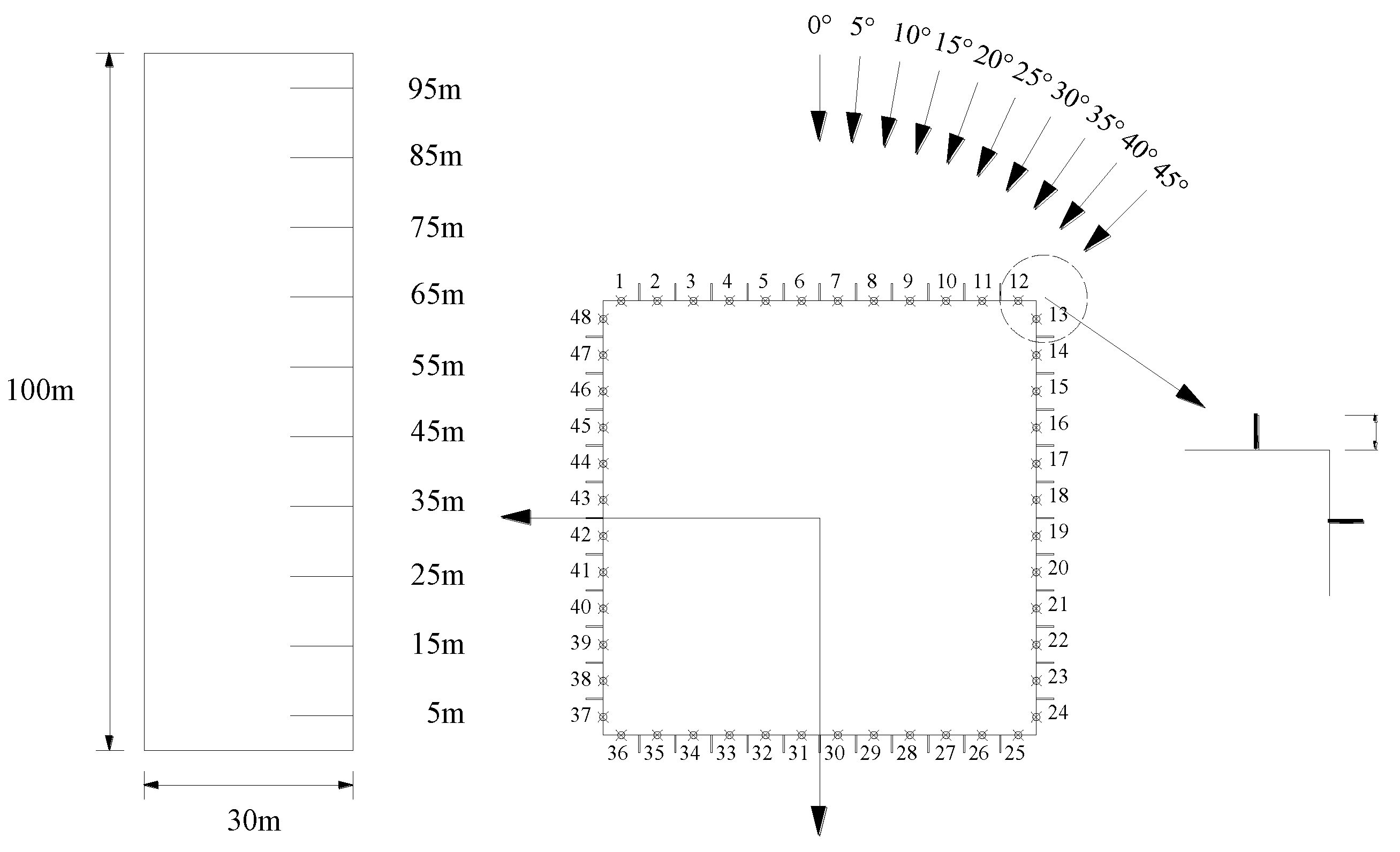
2.2. Wind Tunnel Test

The wind tunnel tests were conducted in the ZD-1 boundary layer wind tunnel at Zhejiang University, which had a test section of 4 m (width) by 3 m (height). The pressure scanners in association with a digital service module (DSM4000, Scanivalve Corporation, Washington, DC, USA) were utilized to record the wind pressures on the model. The fluctuating wind pressures were recorded at a sampling frequency of 312.5 Hz with a duration of 64 s. The wind tunnel tests were carried out in a uniform flow with a wind speed of 11.20 m/s and a turbulence intensity of 0.4%. To eliminate the influence of the near floor viscous layer on the test result, the test models were placed on a large plate that was 30 cm above the ground. The blockage ratios in the tests were less than 3.5%, which ensures that the blockage-caused distortion effects on the flow are negligible [17]. Considering the symmetry of the model, wind incidence angles of 0°–45° with an interval of 5° were tested in the experiments as shown in Figure 3.

2.3. Data Processing

The measured wind pressure at each tap can be expressed as a non-dimensional pressure coefficient Cp in the form of:
C p = P i P 1 2 ρ V 2
where Pi is the measured wind pressure, P is the static pressure at the reference point, V represents the incoming wind velocity equal to 11.2 m/s herein, and ρ represents the air density with a value of 1.25 kg/m3.
Due to the biaxial symmetry in the x and y directions (see Figure 3), only the wind loads in the x-direction are presented herein. The resultant wind force per unit height in the x-direction for the k-th pressure tap layer is denoted as Fx,k, which can be obtained by:
F x , k = i = 1 N 1 2 ρ V 2 C p i , x l i
where N is the total number of pressure taps in the k-th layer, i is the pressure tap number, Cpi,x is the x-component of the pressure coefficient for the i-th pressure tap Cpi, and li is the control length of the pressure tap i.
The non-dimensional resultant layer force coefficient in the x-direction μx can thus be determined by:
μ x = F x 1 2 ρ V 2 B
As shown in Figure 4, the resultant layer force coefficient μx can also be expressed as the superposition of the windward component μx,w and the leeward component μx,l.
The base shear coefficient CFx and the base bending coefficient CMy corresponding to the x-direction (see Figure 4), can be estimated by integrating the layer forces, thus:
C F x = j = 1 M F x , j h j 1 2 ρ V 2 B H
C M y = j = 1 M F x , j h j H j 1 2 ρ V 2 B H 2
where M is the number of the pressure tap layers, hj is the vertical control width of the j-th tap layer, and Hj is the elevation height of the j-th tap layer.

3. Mean Wind Pressure Coefficient at a Typical Wind Incidence Angle (θ = 0°and 45°)

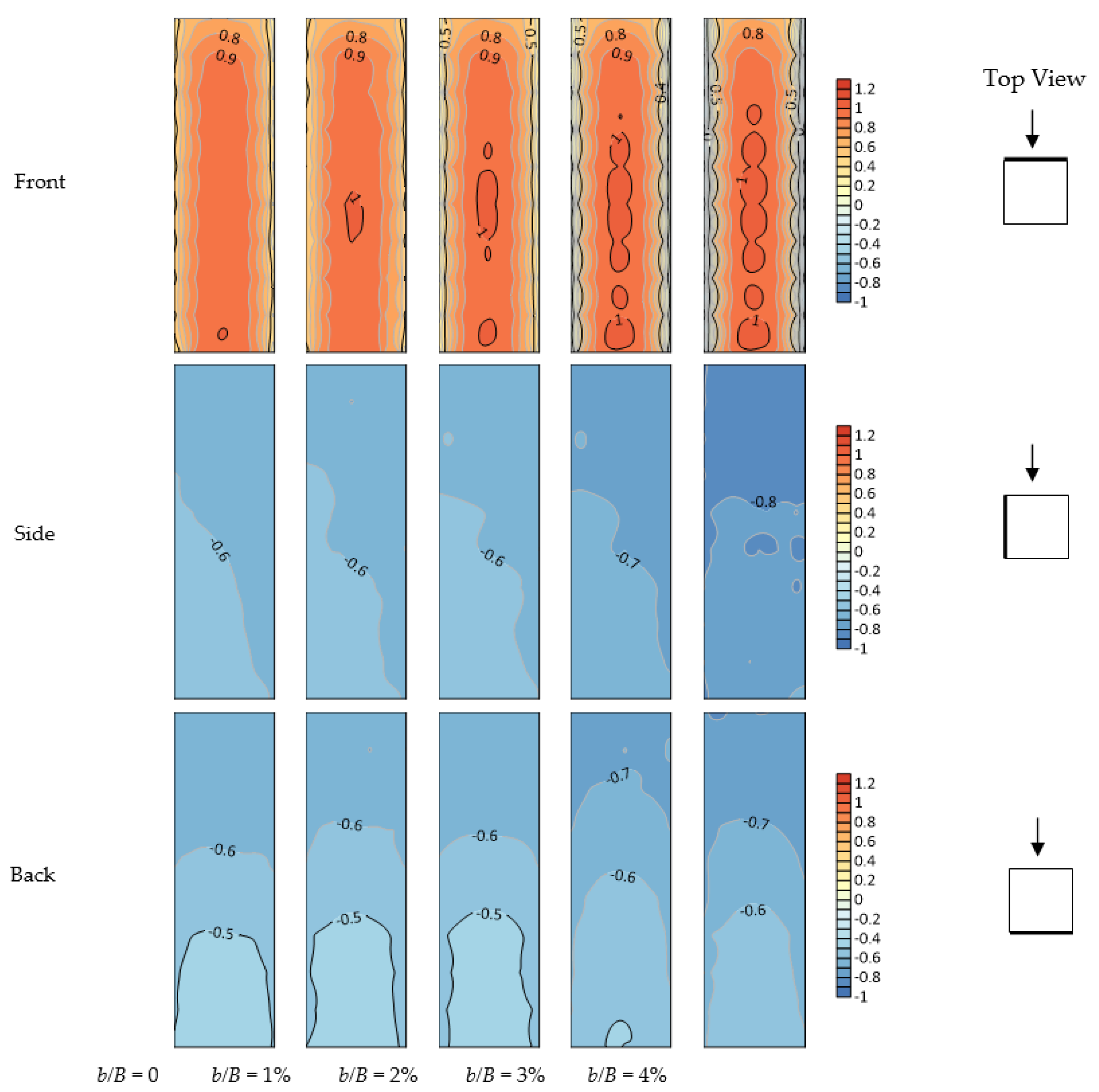
3.1. Mean Wind Pressure Coefficient at a Wind Incidence Angle of 0°

Figure 5 shows the contour plot of wind pressure coefficients Cp on the front, side, and back surfaces of the building with various extensional depths of vertical rib at the wind incidence angle of 0°. It can be observed that the wind pressure near the top of the building shows relatively smaller values compared to that in the other regions due to the three-dimensional flow effect. The maximum wind pressure coefficient of the basic model (i.e., smooth façade) is slightly smaller than that of the other models. This is because the vertical rib behaves like “wind catching” near the middle of the windward surface and keeps the air stationary between the two neighboring ribs, resulting in a larger positive pressure than that without ribs. Compared to the basic model, the negative pressure area on the left and right edges of the front surface shows an increasing trend with the increase in the rib extensional depth. This may result from the local air recirculation at the outermost vertical rib, which enhances the flow separation around the edge of the front surface. The side surface is mainly subjected to negative wind pressure due to the flow separation, and the wind suction on this surface increases slightly with the increase in the rib extensional depth, which may be partially attributed to the superposition of the local air recirculation from the outmost vertical rib and the flow separation at the building corner. Regarding the back face located in the wake zone, the negative wind pressures on the models with b/B = 3% and b/B = 4% are larger than those of the other models.
To compare the difference in the wind pressures between different rib cases in detail, the wind pressure coefficient Cp at the middle height of 55 m is illustrated in Figure 6 for various extensional depths. It shows that Cp in the middle of the front surface is very close for the five tested cases, whereas that near the left and right edges varies from a positive value of 0.4 to a negative value of about −0.8 with the increase in b/B. For the side surface, the negative wind pressure, i.e., wind suction, increases with the rib extensional depth. Under the case of b/B = 4%, the largest increment appears at the windward end of the side surface (i.e., measuring point 13), reaching about 50%, while in the cases of b/B within 2%, the wind suctions are quite similar on the side walls. A similar phenomenon can also be found on the back surface, that is, the models with b/B = 3% and 4% result in much larger negative wind pressures while the other rib cases show an insignificant difference in wind pressure. Therefore, it may be concluded that for test cases, the use of a large extensional depth (e.g., b/B ≥ 3%) of surface-attached vertical rib could significantly affect the wind pressures on the side and back surfaces and the left and right edges of the front surface.

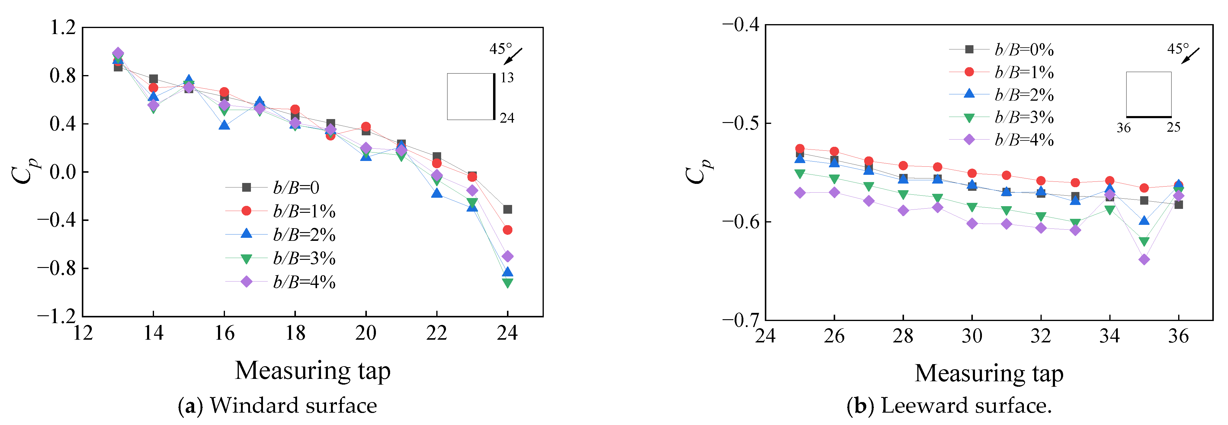
3.2. Mean Wind Pressure Coefficient at a Wind Incidence Angle of 45°

For a typical oblique wind incidence angle of 45°, Figure 7 shows the wind pressure coefficient Cp measured on the windward and leeward surfaces under various rib extensional depths. It can be found that large positive pressures appear on the upwind area of the windward surface, but these decay rapidly and become negative on the downwind area of the windward wall. The negative pressure area enlarges with the increase in the extensional depth. This may be attributed to the contribution of local recirculation caused by the downwind vertical ribs with a large depth, leading to an earlier air separation in the wake area. Figure 7 also indicates that increasing the rib extensional depth has a slight effect on the distribution of the negative wind pressure on the leeward surface.
Similarly, for this oblique wind incidence angle, the wind pressure coefficient Cp at the middle height of 55 m on the windward and leeward faces is shown in Figure 8. It shows that the positive wind pressures on most measuring points of the windward surface are quite similar between different rib cases while a sharp increase in the negative wind pressure was found on the downwind area (e.g., measuring tap 24) as the rib depth increased. Negative wind pressure appeared on an earlier measuring point when using a larger rib depth. This is consistent with the finding of Figure 7. However, on the leeward face, the negative wind pressure shows a moderate increase (e.g., within 10% from the smooth surface to the largest rib depth case) with the increase in the rib extensional depth while that on the model with a b/B ≤ 2% is quite similar.

4. Layer Force Coefficient

The windward, leeward, and resultant drag force coefficients defined in the current codes are equal to the windward (i.e., μx,w), leeward (i.e., μx,l), and resultant (i.e., μx) layer force coefficients under the case of normal approaching wind to the building surface in this study. For the models tested (H = 100 m, D = 30 m, B = 30 m) herein, the corresponding layer force coefficients determined by various codes [20,21,22,23,24,25,26,27] are tabulated in Table 2. It can be observed that the ASCE, AS/NZS, NBCC, and AIJ codes provide the same layer force coefficients while the EN code and HK, China code give the maximum and minimum values, respectively.
For a wind incidence angle of 0°, Figure 9 shows the layer force coefficient on the windward and leeward facades along the height under different rib extensional depths. It can be observed that the windward layer force coefficients (i.e., μx,w) of the model with a smooth facade and b/B = 1% are almost around 0.8, which is consistent with all the codes’ provisions presented herein. The μx,w near the building top is relatively smaller than that in other regions due to the three-dimensional flow effect. As b/B increases from 1% to 4%, μx,w may decrease by about 28%. When it comes to the leeward surface, μx,l for the models with b/B = 1% and 2% is close to that of the smooth facade. However, when the model has a rib extensional depth beyond 2% of the building width, μx,l increases with b/B, which may exacerbate wind suction on the leeward facade by about 17%. It is worth noting that the absolute value of the leeward layer force coefficient increases with the height, whereas that suggested by the codes remains constant along the height, leading to underestimation of the wind suction at the building top.
For a wind incidence angle of 0°, Figure 10 shows the resultant layer force coefficient along the height under different rib cases. It shows that the resultant layer force coefficient along the height presents a shape of “7” and reaches the maximum value at the height of about 0.8 H. The resultant layer force coefficients of all testing cases decrease with the increase in b/B, indicating that the use of surface-attached rib is beneficial to reducing the total layer wind load acting on the building. Compared to the smooth model, the model with the largest rib depth can reduce the layer wind load by about 9% at most. The EN and GB50009 codes provide conservative μx for most cases while the HK, China code may lead to an underestimation of the resultant layer force.

5. Base Shear and Bending Moment Coefficients

To explore the influence of the rib extensional depth on the overall base wind effects, Figure 11 presents the base shear force coefficient CFx and base bending moment coefficient CMy under different wind incidence angles for all tested cases. To accurately compute the base shear force and base bending moment, the measured layer force coefficients are interpolated with the cubic spline algorithm to derive the corresponding values for unmeasured layers. The wind incidence angle ranges from 0° to 90°, where the force coefficients in the angles of 45°~90° are attained symmetrically from those in the y-direction under incidence angles of 0°~45°. Figure 11 shows that the base shear and base bending moment reach their maximum values at the wind incidence angle of 0°. When the wind incidence angle of the minimum value shifts from 75° to 85°, b/B increases from 0% to 4%. The base shear and base bending moment for cases of b/B between 0% and 2% share almost the same variation trend with the wind incidence angles while the models with b/B = 3% and 4% bear larger maximum negative pressures at the wind incidence angle of 80° and 85°, respectively, but smaller maximum positive pressure at the wind incidence angle of 0°. The maximum absolute values of both the base share and base bending moment appear at the incidence angle of 0°, making it the control case for wind-resistant design. In this case, the addition of vertical ribs with a large extensional depth (e.g., 0.04B) will improve the wind-resistant performance of a high-rise building by reducing the base shear and bending moment by 8.8% and 7.4%, respectively.

6. Conclusions

This study employed wind tests to investigate the influence of attached vertical ribs with various moderate extensional depths on the wind pressure of a high-rise building. The wind pressure distribution on different building surfaces, layer force coefficient along the height, and overall base shear coefficient and bending moment coefficient were analyzed and compared between different rib extensional depths. Comparison of the layer force coefficient with that in different code provisions was also conducted. The main conclusions are:
(1)
On the windward face, the negative pressure area increases with the rib extensional depth. This may result from the local recirculation caused by the outmost vertical ribs, which enhances flow separation around the building. The negative wind pressures on the leeward surface show a slight increase with the increase in the rib extensional depth.
(2)
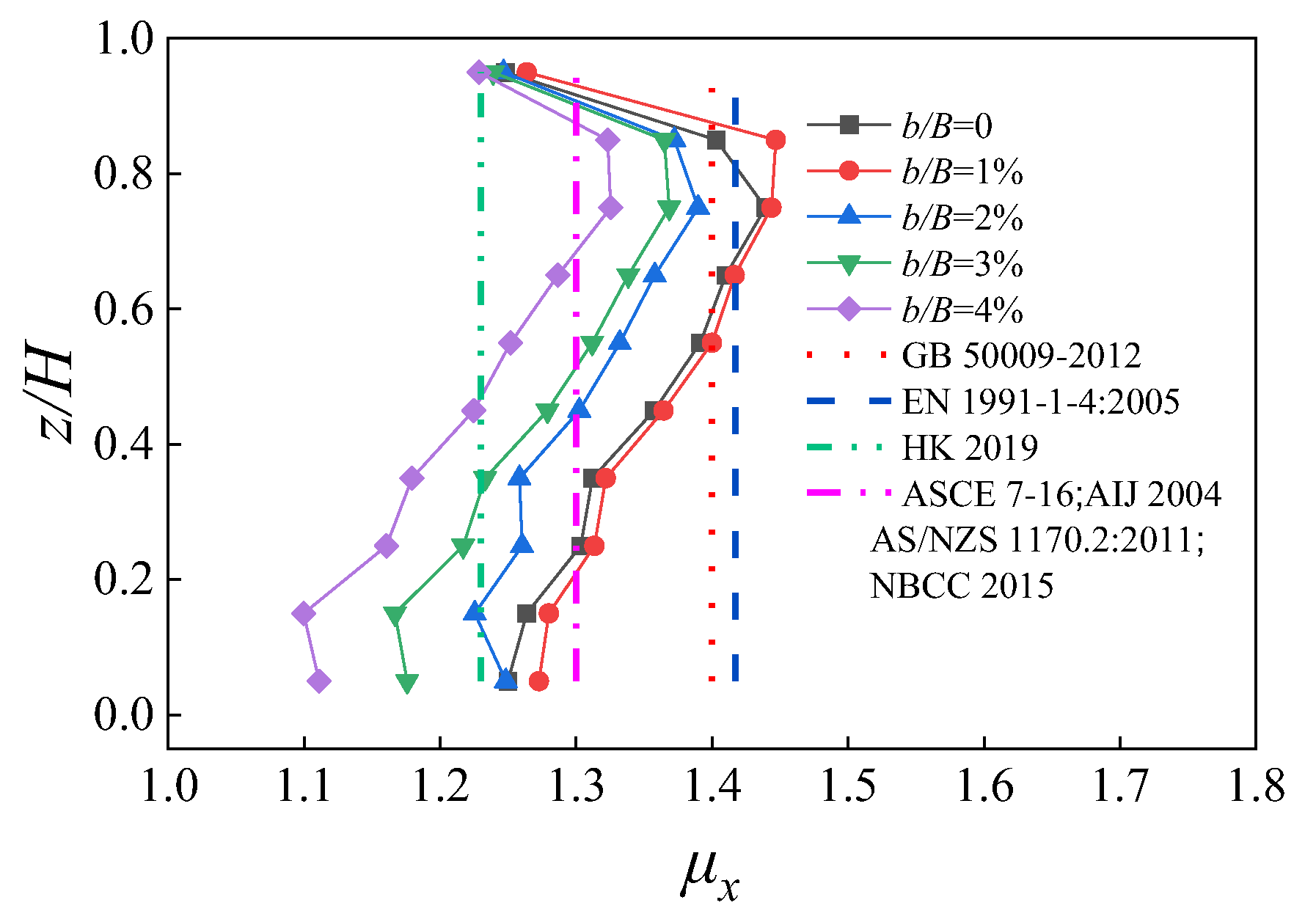
The experimental results show that the resultant layer force coefficient along the height shows a shape of “7” and reaches the maximum value at a height of 0.8 H. Compared to the experimental results, the resultant layer force coefficients provided by EN 1991-1-4:2015 and GB 50009-2012 are conservative for most cases, whereas those provided by the HK, China code lead to an underestimated evaluation. Increasing the rib extensional depth will significantly reduce the positive windward layer force by 28% but moderately increase the negative leeward layer force by 17%. The use of surface-attached ribs is beneficial in reducing the resultant layer wind pressure on the building by a maximum of 9%.
(3)
When b/B is below 2%, the addition of vertical ribs has limited effects on the overall base shear and base bending moment. An increase in the rib extensional depth to 4% of the building width will reduce the maximum base shear and bending moment by 8.8% and 7.4%, respectively, indicating the effectiveness of vertical ribs in improving the wind-resistant performance of a high-rise building.

Author Contributions

Conceptualization, G.S., Y.J. and H.X.; methodology, G.S., Y.J. and S.Y.; investigation, Y.J., G.S., S.Y. and H.X.; writing—original draft preparation, Y.J., G.S. and H.X.; writing—review and editing, G.S. and H.X. All authors have read and agreed to the published version of the manuscript.

Funding

The authors greatly appreciate the support by the National Natural Science Foundation of China (Grant No. 51578505 and 52178511) and Zhejiang Provincial Natural Science Foundation of China (Grant No. LGG21E080009). The opinions and statements do not necessarily represent those of the sponsors.

Institutional Review Board Statement

Not applicable.

Informed Consent Statement

Not applicable.

Data Availability Statement

Data is available upon reasonable request.

Conflicts of Interest

The authors declare that they have no known competing financial interests or personal relationships that could influence the work reported herein.

References

  1. Sheng, R.; Perret, L.; Calmet, I.; Demouge, F.; Guihot, J. Wind tunnel study of wind effects on a high-rise building at a scale of 1:300. J. Wind Eng. Ind. Aerod. 2018, 174, 391–403. [Google Scholar] [CrossRef]
  2. Thordal, M.S.; Bennetsen, J.C.; Capra, S.; Kragh, A.K.; Holger, H. Towards a standard CFD setup for wind load assessment of high-rise buildings: Part 2–Blind test of chamfered and rounded corner high-rise buildings. J. Wind Eng. Ind. Aerod. 2020, 205, 104282. [Google Scholar] [CrossRef]
  3. Elshaer, A.; Bitsuamlak, G.; Damatty, A. Enhancing wind performance of tall buildings using corner aerodynamic optimization. J. Eng. Struct. 2017, 136, 133–148. [Google Scholar] [CrossRef]
  4. Asghari, M.; Kargarmoakhar, R. Aerodynamic mitigation and shape optimization of buildings: Review. J. Build. Eng. 2016, 6, 225–235. [Google Scholar] [CrossRef]
  5. Kim, Y.C.; Tamura, Y.; Tanaka, H.; Ohtake, K.; Bandi, E.K.; Yoshida, A. Wind induced responses of super-tall buildings with various atypical building shapes. J. Wind Eng. Ind. Aerod. 2014, 133, 191–199. [Google Scholar] [CrossRef]
  6. Kim, Y.C.; Kanda, J. Wind pressures on tapered and set-back tall buildings. J. Fluid Struct. 2013, 39, 306–321. [Google Scholar] [CrossRef]
  7. Miyashita, K.; Katagiri, J.; Nakamura, O.; Ohkuma, T.; Tamura, Y.; Itoh, M.; Mimachi, T. Wind-induced response of high-rise buildings effects of corner cuts or openings in square buildings. J. Wind Eng. Ind. Aerod. 1993, 50, 319–328. [Google Scholar] [CrossRef]
  8. Kim, W.S.; Yoshida, A.; Tamura, Y. Wind-induced aerodynamic instability of super-tall buildings with various cross-sectional shapes. Int. J. High-Rise Build. 2019, 8, 303–311. [Google Scholar]
  9. Zhang, Z. Discussion on design wind load of facade decorative fittings for high-rise buildings. J. Build. Struct. 2019, 49, 46–52. (In Chinese) [Google Scholar]
  10. Stathopoulos, T.; Zhu, X. Wind pressures on building with appurtenances. J. Wind Eng. Ind. Aerod. 1988, 31, 265–281. [Google Scholar] [CrossRef]
  11. Shen, G.; Qian, T.; Yang, X.; Fang, H.; Lou, W. Study of wind loads on torsion shaped high-rise building with outer pierced ornament structure. J. Build. Struct. 2013, 34, 68–74. (In Chinese) [Google Scholar]
  12. Hu, G.; Song, J.; Hassanli, S.; Ong, R.; Kwok, K.C.S. The effects of a double-skin façade on the cladding pressure around a tall building. J. Wind Eng. Ind. Aerod. 2019, 191, 239–251. [Google Scholar] [CrossRef]
  13. Zheng, X.; Montazeri, H.; Blocken, B. CFD analysis of the impact of geometrical characteristics of building balconies on near-façade wind flow and face pressure. Build. Environ. 2021, 200, 107904. [Google Scholar] [CrossRef]
  14. Yuan, K.; Hui, Y.; Chen, Z. Effects of facade appurtenances on the local pressure of high-rise building. J. Wind Eng. Ind. Aerod. 2018, 178, 26–37. [Google Scholar] [CrossRef]
  15. Hui, Y.; Yuan, K.; Chen, Z.; Yang, Q. Characteristics of aerodynamic forces on high-rise buildings with various façade appurtenances. J. Wind Eng. Ind. Aerod. 2019, 191, 79–90. [Google Scholar] [CrossRef]
  16. Hui, Y.; Liu, J.; Wang, J.; Yang, Q. Effects of facade rib arrangement on aerodynamic characteristics and flow structure of a square cylinder. Build. Environ. 2022, 214, 108924. [Google Scholar] [CrossRef]
  17. Liu, J.; Hui, Y.; Yang, Q.; Tamura, Y. Flow field investigation for aerodynamic effects of surface mounted ribs on square-sectioned high-rise buildings. J. Wind Eng. Ind. Aerod. 2021, 211, 104551. [Google Scholar] [CrossRef]
  18. Huang, D.; He, S.; Zhu, X.; He, X. Influence of surface roughness on wind load and wind-induced response of super-tall building. J. Hunan Univ. (Nat. Sci.) 2017, 44, 41–51. (In Chinese) [Google Scholar]
  19. Yang, Q.; Liu, Z.; Hui, Y.; Li, Z. Modification of aerodynamic force characteristics on high-rise buildings with arrangement of vertical plates. J. Wind Eng. Ind. Aerod. 2020, 200, 104551. [Google Scholar] [CrossRef]
  20. ASCE Manual No. 49: 2021; Wind Tunnel Testing for Building and Other Structures. ASCE: Reston, VA, USA, 2021.
  21. GB 50009-2012; Load Code for the Design of Building Structures. Architecture and Building Press: Beijing, China, 2012. (In Chinese)
  22. ASCE 7-22; Minimum Design Loads and Associated Criteria for Buildings and Other Structures. ASCE: New York, NY, USA, 2022.
  23. European Standard EN 1991-1-4; Actions on Structures. European Committee for Standardization: Brussels, Belgium, 2004.
  24. AS/NZS 1170.0; Australian/New Zealand Standard. Standards Australia: Sydney, NSW, Australia; Standards New Zealand: Wellington, New Zealand, 2011.
  25. National Building Code of Canada 2015; Canadian Commission on Building and Fire Codes. National Research Council of Canada: Ottawa, ON, Canada, 2015.
  26. RLB-AIJ: 2004; Recommendations for Loads on Buildings. Architectural Institute of Japan: Tokyo, Japan, 2004.
  27. Code of Practice on Wind Effects in Hong Kong; Buildings Department of Hong Kong: Hong Kong, China, 2019.
Figure 1. Smooth façade model in the wind tunnel (b/B = 0).
Applsci 12 09984 g001
Figure 2. Test models with four rib extensional depths.
Applsci 12 09984 g002
Figure 3. Layout of pressure measuring points, test wind incidence angles, and coordinates of the measured wind force.
Applsci 12 09984 g003
Figure 4. Illustration of the base forces, base bending moment, and layer forces of the building.
Applsci 12 09984 g004
Figure 5. Distribution of the mean wind pressure coefficients on the front, side, and back faces (θ = 0°).
Applsci 12 09984 g005
Figure 6. Mean wind pressure coefficients at a height of 55 m on the front, side, and back surfaces (θ = 0°).
Applsci 12 09984 g006
Figure 7. Distribution of the mean wind pressure coefficients on the windward and leeward faces (θ = 45°).
Applsci 12 09984 g007
Figure 8. Distribution of the mean wind pressure coefficients at 55 m on the windward and leeward faces (θ = 45°).
Applsci 12 09984 g008
Figure 9. Layer force coefficients along building height on the windward and leeward surfaces (θ = 0°).
Applsci 12 09984 g009
Figure 10. Resultant layer force coefficients along the building height (θ = 0°).
Applsci 12 09984 g010
Figure 11. Base shear force and bending moment coefficients of a building under θ = 0°–90°.
Applsci 12 09984 g011
Table 1. Parameters of the vertical ribs at full scale.
Model Casesb/mb/B (%)
Smooth facade00
10.31
20.62
30.93
41.24
Table 2. Layer force coefficient regulated in different codes.
Codeμx,wμx,lμx
GB50009-20120.8−0.61.4
ASCE 7-220.8−0.51.3
EN 1991-1-4:20050.8−0.6171.417
AS/NZS 1170.2:20110.8−0.51.3
NBCC 20150.8−0.51.3
AIJ 20040.8−0.51.3
HK, China 2019--1.23
Publisher’s Note: MDPI stays neutral with regard to jurisdictional claims in published maps and institutional affiliations.

