Article

Helmholtz Coils Based WPT Coupling Analysis of Temporal Interference Electrical Stimulation System

1
School of Electrical Engineering, Hebei University of Technology, Tianjin 300401, China
2
State Key Laboratory of Reliability and Intelligence of Electrical Equipment, Hebei University of Technology, Tianjin 300401, China
3
Hebei Key Laboratory of Bioelectromagnetics and Neural Engineering, Hebei University of Technology, Tianjin 300130, China
4
Tianjin Key Laboratory of Bioelectricity and Intelligent Health, Hebei University of Technology, Tianjin 300130, China
*
Author to whom correspondence should be addressed.
Appl. Sci. 2022, 12(19), 9832; https://doi.org/10.3390/app12199832
Submission received: 21 August 2022 / Revised: 19 September 2022 / Accepted: 23 September 2022 / Published: 29 September 2022

Abstract

:
Electrical nerve stimulation (ENS) is clinically important in treating neurological diseases. This paper proposes a novel temporally interfering wireless power transfer (WPT) system, based on Helmholtz coils, to address energy depletion and the miniaturization of wireless power transfer systems for implantable devices. Compared to conventional WPT systems, this paper uses Helmholtz coils with a centrosymmetric structure as the transmitting coils. A more uniform and stable magnetic field was obtained through structural improvements. It also improves the problem that changes in the receiving coil’s position affect the transmission power’s stability. Based on the principle of temporal interference (TI), two transmitting coils with a slight frequency difference generate a superposition of magnetic fields on the receiving coil and then induce a low-frequency electrical signal on it. The electrical stimulation system applies stimulation parameters of a specific intensity and frequency directly to the target nerve with electrodes connected to it. This eliminates the need for the conventional high-frequency signal to low-frequency signal processing circuitry and reduces the device’s size. In this paper, numerical calculations and an experimental verification of the proposed system are carried out. The magnetic field distribution and the receiving coil current waveform of the system were tested to verify the effectiveness and stability of the proposed design. The experimental results showed that the proposed wireless power transfer system can generate electrical signals of the desired waveform in the receiving coil. Its frequency of 10 Hz and amplitude of 42.4 mA meet the requirements for the electrical stimulation of the sciatic nerve.

1. Introduction

Complex regional pain syndrome type I (CRPS–I) is a chronic neuropathic pain syndrome, secondary to limb injury, which occurs in up to 48.8% of patients who have had a stroke or fracture [1]. It mainly presents clinically with symptoms of intractable and variable pain, malnutrition, and functional impairment [2,3]. The clinical treatment of CRPS–I is primarily conservative in terms of medication. However, due to the long treatment period, high dosage, and side effects, the results are not satisfactory. In recent years, interventional therapies have been widely used to treat neuropathic pain. In order to fill the gap in spinal cord electrical stimulation, Buwembo et al. proposed a CRPS–I therapy, using an implantable device to stimulate the sciatic nerve directly, and clinically validated its effectiveness [4]. Compared to spinal cord stimulation (SCS), this method limits the stimulation area to the foot and has no additional impact on the non-working area, enabling an efficient and focused treatment of intractable pain [4]. Currently, it is common for implantable devices to be battery powered [5,6]. Although the power density of batteries is increasing, the limitations of the implantation space leave the batteries facing the dilemma of running out of power [7]. Studies have shown that over 60% of pacemakers need to be replaced for battery reasons within 5–12 years [8]. In addition, the second surgery that accompanies the battery replacement places a double financial and physical burden on the patient, making battery power a significant limitation in the long-term operation of implantable devices. Nevertheless, the wireless power transmission of implantable devices can solve the above problems [9,10]. It enables an indefinite implantation in the body without facing the problem of running out of power [11]. Traditional wireless power transfer (WPT) devices usually have a transmission frequency in the MHz range [12,13]. However, as the frequency of the applied stimulus is mostly in the tens to hundreds of hertz, the device needs to be equipped with a frequency conversion circuit to transform the signal from high to low frequencies [14]. Both this signal processing module and the battery component take up additional volume in the implanted device, hindering the miniaturization of the size of the implantable devices. Therefore, optimizing the implantable stimulation systems, while ensuring effectiveness, is a new research direction for CRPS treatment. This paper uses the principle of magnetic field superposition based on temporal interference (TI), eliminating the need for processing circuits that convert high-frequency signals to low-frequency signals in conventional WPT. This provides a new idea for the miniaturization of implantable devices.
A comparison of the characteristics of the different power supply methods for implantable devices is shown in Table 1.
Different circuit topologies have different transmission characteristics for magnetically coupled resonant wireless power transfer (MCR-WPT) systems. Coupling analysis of the proposed system was necessary to visually analyze and improve the configuration and spatial distribution of the coupling coils and thus stabilize the energy transfer efficiency of the whole system. The main methods for the quantitative analysis of the operating principle of the MCR-WPT were the coupled-mode theory and the circuit theory [15]. However, the coupled-mode theory was too theoretical and not sufficiently intuitive for optimizing the parameters of a system [16]. Therefore, this paper abstracts the system using the circuit model and uses the basic theory of resonant circuits to elaborate and analyze the transmission laws of the system.
According to the Hodgkin–Huxley (HH) theory of neurophysiology and the McIntyre–Richardson–Grill (MRG) model, the excitability of nerve cells results from the different permeability of the cell membrane to sodium, potassium, and oxygen ions [17,18,19]. Externally applied electrical stimulation of a specific intensity can cause a series of morphological and physiological changes in the nerve cells at the site of action. The nerve impulses generated are identical to the action potentials induced by natural excitation, thereby modulating the functional response of the nerve circuits and surrounding areas. As the applied electrical stimulation acts directly on the target neuron, it can activate the target neuron while preventing the accidental excitation of other neurons. It has an excellent temporal and spatial resolution and therapeutic effects. Combined with the properties of the neuron itself, below-threshold electrical stimulation can only cause depolarization of the cell membrane. Therefore, only when the intensity of the electrical stimulation reaches the threshold will an effective action potential be excited and produce a therapeutic effect [20]. At the same time, due to the low-frequency nature and fatigue of nerve cells, only a low-frequency alternating current or direct current can induce the action potentials. Therefore, the frequency range for electrical nerve stimulation is mainly in the tens to hundreds of hertz levels [21].
The implementation of temporally interfering electric fields to apply stimulation directly to the target region requires acquiring an accurate current density and field strength distribution. However, due to the dispersion of human tissues [22], the dielectric constant becomes smaller when the frequency increases. It will result in the actual electric field waveform and injected current density at different locations in the human body being different from that expected. Moreover, due to the specificity of the individual tissues in the human body, it is often difficult to ensure a high spatial accuracy in practical applications, making the scheme much less operable. The above problems can be avoided using electrical stimulation through induced currents generated in the electrodes by a magnetic field. Since the magnetic permeability of biological tissue is close to a vacuum, the magnetic field can penetrate human tissue without attenuation and distortion [23]. The induced current waveform obtained at the electrodes is stable and independent of depth. Both demonstrate the feasibility of a treatment protocol for targeted electrical stimulation with induced currents in the electrodes.
This paper proposes an MCR-WPT electrical stimulation system based on temporal interference in conjunction with the mechanism of action of electrical stimulation signals on nerve cells. In contrast to conventional implantable devices, this system uses temporal interference to generate an envelope-modulated magnetic field at a specific frequency for low-frequency wireless power transfer. The device directly applies electrical stimulation of sufficient intensity to the target nerve using the same frequency current from the electrodes connected to the receiving coil. It eliminates the need for a frequency converter and reduces the implanted device’s size while ensuring the effectiveness of the stimulation. It also eliminates the need for implanted batteries, lowering the threshold for the use of implantable neurostimulation devices and reducing the burden on the body. Given the variable position of the receiving coil, this system uses Helmholtz coils as the transmitters. The stability and uniformity of the magnetic field are ensured to the greatest extent possible, thus ensuring a stable electrical stimulation function of the nerve electrodes.

2. Principles and Methods Analysis

2.1. Magnetically Coupled Resonant Wireless Power Transfer System

Magnetically coupled resonant wireless power transfer technology was first proposed by a Massachusetts Institute of Technology research team in 2007 [24]. This technique uses the concept of near-field coupling and the principle of resonance. The circuit parameters of the transmitter and receiver are set appropriately to have the same resonant frequency. When a current at the resonant frequency is passed, the system will reach a resonant state, thus achieving an efficient energy transfer from the transmitter to the receiver.
The magnetic field signal at the resonant frequency is first obtained through the high-frequency signal generator. Then, it is added to the transmitting coil after the high-frequency power amplifier increases the transmission power. At that point, the transmitting coil is matched to the transmitter circuit through an impedance matching network. The transmitter transmits the energy via magnetic coupling to the receiver, which rectifies and filters the received high-frequency electricity to provide energy for the load. Due to the resonance characteristics, the transmission efficiency of the system is highly selective for frequency. When the operating frequency deviates from the coil’s resonant frequency, the transmission efficiency decreases sharply.
The key to the efficient transmission of MCR-WPT lies in the fact that the whole system works in a resonant state. The system establishes a stable energy transmission channel between the coils through magnetically coupled resonance, thus enabling an efficient wireless transmission of non-radiative energy. Compared to the traditional magnetic inductive coupling WPT system, the MCR-WPT system has the advantages of being highly efficient and having a long transmission range and greater penetration into non-magnetic media. This is why the MCR-WPT system has a broader application prospect in the field of implantation device engineering.

2.2. Wireless Power Transfer System Based on Helmholtz Coils

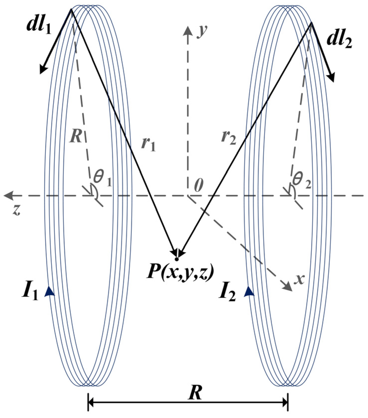
2.2.1. Magnetic Fields Generated by Helmholtz Coils

Research has shown that magnetic field non-uniformity in MCR-WPT systems can lead to resonant frequency splitting phenomena [25]. This leads to an impedance mismatch between the transmitting and receiving coils and system detuning, which in turn affects the energy transmission of the system [26]. Therefore, for the MCR-WPT system, a uniform magnetic field is essential to ensure the stability of the energy transmission efficiency in the operating area. Research has shown that using Helmholtz coils is an adequate solution for obtaining a uniform but time-varying magnetic field over a large area [27,28]. Helmholtz coils are a pair of identical, parallel, and co-axial circular current-carrying coils, with current flowing in the same direction through both coils and a distance between them equal to the coil radius. According to the superposition principle, the spatial magnetic field distribution is the vector sum of the magnetic flux densities produced by the two energized coils [29]. The magnetic field outside the two coils gradually weakens, but a wide range of uniform magnetic fields can be generated near the midpoint of the two axes. The distribution of the magnetic field generated by the Helmholtz coils was analyzed by the following analytical method.
First, assume that the radius of the two identical coils is R , the distance between the coils is equal to the radius, the number of turns is N , and the currents in the two coils are in the same direction with magnitudes I 1 and I 2 , respectively. Next, establish a right-angle coordinate system in space as shown in Figure 1, with the coaxial line of the two coils as the z-axis. The coordinate origin O , x-axes, and y-axes are all located in the plane of symmetry between the centers of the two coils.
Assuming that point P ( x , y , z ) is any point in space, the magnetic flux density B P at point P can be regarded as a vector superposition of the flux densities generated by the two coils individually.
First, calculate the magnetic field generated by a single coil at point P . As shown in Figure 1, the magnetic flux density B , generated by a single n-turn coil at any point in space, is given by the Bio–Savart law as:
B = n μ 0 4 π l I d l × r r 3
According to the principle of vector superposition, the magnetic flux density vector B P of the Helmholtz coils at any point P in space is known to be:
B P = n μ 0 4 π ( l 1 ( I 1 d l 1 × r 1 r 1 3 ) + l 2 I 2 d l 2 × r 2 r 2 3 )
where θ is the angle between the current element I d l and the positive direction of the x-axis. Assuming that the current element I d l is located in the upper side space of the x o y plane, its corresponding spatial location coordinate is: ( R cos θ , R sin θ , 0.5 R ) .
The three components of the x, y, and z directions of the current element I d l are: ( I R sin θ d θ , I R cos θ d θ , 0 ) .
The vector r in space pointing from the current element to the point P is: ( R cos θ x , R sin θ y , 0.5 R z ) .
Therefore:
I d l × r = | i j k I d l x I d l y I d l z r x r y r z | = | i j k I R sin θ d θ I R cos θ d θ 0 R cos θ x R sin θ y 0.5 R z |
From the superposition theorem, the x, y, and z directional components of the magnetic flux density vector B produced by the Helmholtz coil at point P are:
B P X = n μ 0 R 4 π 0 2 π ( ( 0.5 R z ) I 1 r 1 3 + ( 0.5 R z ) I 2 r 2 3 ) cos θ d θ
B P Y = n μ 0 R 4 π 0 2 π ( ( 0.5 R z ) I 1 r 1 3 + ( 0.5 R z ) I 2 r 2 3 ) sin θ d θ
B P Z = n μ 0 R 4 π 0 2 π ( I 1 r 1 3 + I 2 r 2 3 ) ( R + y sin θ + x cos θ ) d θ
Based on the derivation of the above equations, the magnetic field distribution of the Helmholtz coils at each point in space can be calculated by the analytical method.

2.2.2. Circuit Analysis of a WPT System with Helmholtz Coils

The law of electromagnetic induction shows that when the current in the transmitting coil changes, the resulting magnetic chain couples to the receiving coil and generates an induced electric potential in the receiving coil [30]. The free-space energy transfer system is mapped into a circuit model according to electromagnetic correlations. The approach to analyzing the characteristics of magnetically coupled resonant systems from the point of view of circuit principles is universal. The basic idea can be formulated as follows: firstly, a system of Kirchhoff equations for the equivalent circuit is established from the circuit topology, and the mathematical expressions for the transmission efficiency and corresponding parameters are obtained after solving the system of equations. Finally, the transmission characteristics of the MCR-WPT system are theoretically analyzed with practice [16,31]. This is similar to a transformer model, with the difference being that the magnetic circuit is air rather than ferromagnetic material.
An equivalent circuit model of a WPT system, consisting of two transmitting coils with one receiving coil, is shown in Figure 2.
V S is the power supply to the transmitting coil, R S is the internal resistance of the power supply; R 1 and R 2 are the parasitic resistances of transmitting coil 1 and transmitting coil 2 respectively, R 3 is the resistance of the receiving coil, and R L is the load resistance. L 1 and L 2 are the inductances of the transmitting coil, and L 3 is the receiving coil inductance. M 12 is the mutual inductance between the two transmitting coils, while M 13 and M 23 are the mutual inductances between the receiving and transmitting coils. Moreover, because the resonant system works at high frequencies, the parasitic capacitance of the inductor coil cannot be ignored. The coil’s series resonant compensation capacitance and the inductor coil’s parasitic capacitance are equivalent to C 1 , C 2 and C 3 . In addition, let the operating angular frequency of the system be w , and the resonant angular frequencies of the transmitting and receiving coils are the same w 0 .
From Maxwell’s equation, it can be seen that there is magnetic coupling and electrical coupling between the coils. However, due to the large inductance of the coils, the magnetic coupling is much stronger than the electrical coupling. Therefore, the electric field coupling can be ignored in the analysis, and only the magnetic coupling between the coils is considered. In order to simplify the analysis, this paper makes the same simplification, noting that R T = R 1 + R 2 + 2 R S , L T = L 1 + L 2 + 2 M 12 . To simplify the calculation, assume that the currents in the transmitting coils are the same, i.e., I 1 = I 2 . In analogy to a conventional two-coil circuit, the Kirchhoff circuit equation can be written as follows, where I 3 is the current in the receiving coil.
{ [ R T + j ω L T + 1 j ω ( 1 C 1 + 1 C 2 ) ] I 1 + j ω ( M 13 + M 23 ) I 3 = 2 V s j ω ( M 13 + M 23 ) I 1 + ( R 3 + R L + j ω L 3 + 1 j ω C 3 ) I 3 = 0
The calculation formula for the inductance of a circular coil is:
L = μ 0 r N 2 [ ln ( 8 r a ) 2 ]
where μ 0 = 4 π × 10 7 H / m is the magnetic permeability in the vacuum, N is the turn number of the coil, r is the radius of the coil, and a is the wire diameter.
Usually, since the receiving coil is located in the middle of the transmitting coil in a three-coil system, the coupling between the transmitting coils is very weak and can be neglected, i.e., M 12 = 0 . The mutual inductances between the transmitting and receiving coils are:
M 13 = μ 0 N 1 N 3 4 π C 1 C 3 d l 1 × d l 3 r = μ 0 N 1 N 3 4 π 0 2 π 0 2 π r 1 r 3 cos ( θ φ ) d θ d φ R Q N
M 23 = μ 0 N 2 N 3 4 π C 2 C 2 d l 2 × d l 3 r = μ 0 N 2 N 3 4 π 0 2 π 0 2 π r 2 r 3 cos ( θ φ ) d θ d φ R Q N
Among them:
R Q N = ( r 1 cos θ r 3 cos φ ) 2 + ( r 1 sin θ r 3 sin φ ) 2 + h 2
where r 1 and r 3 are the radii of the transmitting and receiving coils, respectively, and h is the distance between the transmitting and receiving coils.
According to the resonance principle, the system reaches resonance when the frequency of the two coils is the self-resonant frequency w 0 . At this point, the imaginary part of the coil loop impedance is 0 , and the energy transfer between resonant objects is the most efficient. Combined with the definition of transfer efficiency, the Helmholtz coils WPT system can be obtained when the resonance of the expression of the transfer efficiency is:
η = I 3 2 R L I 1 2 R T + I 3 2 ( R 3 + R L ) = R L R T ( R 3 + R L ) 2 w 0 2 ( M 13 + M 23 ) 2 + ( R 3 + R L )
when the system is in resonance, the system transmission efficiency reaches a maximum value of η max , and the derivative of the above equation, i.e., let η / R L = 0 , the load at this point is noted as R L t o p η , whose value is:
R L t o p η = R 3 1 + w 0 2 ( M 13 + M 23 ) 2 R T R 3
The corresponding maximum transmission efficiency η max is:
η max = w 0 2 ( M 13 + M 23 ) 2 R L t o p η ( R 3 + R L t o p η ) [ w 0 2 ( M 13 + M 23 ) 2 + R T ( R 3 + R L t o p η ) ]
It can be seen that to obtain the theoretical maximum transmission efficiency, the transmitting and receiving coils need to have matched impedance to obtain the same resonant frequency. However, due to the uncertainty of the receiver position, there is no guarantee that it will be at its intended optimal transmission position during the actual energy transfer process. Furthermore, system detuning will lead to a reduction in the transmission efficiency [32,33]. Therefore, ensuring that the system continues to achieve efficient energy transmission when the receiver’s position fluctuates is necessary. There are two common ways to maintain maximum transmission efficiency: One is the frequency tracking method, which uses the closed-loop nature of the phase-locked loop. The frequency of the output signal of the pulse width modulation (PWM) controller is adjusted by tracking the output current frequency on the transmitter side, thus ensuring that the system’s operating frequency is the same as the circuit’s resonant frequency [34]; the other is the optimal load tracking method. It transmits the impedance value, reflection coefficient, or voltage standing wave ratio (VSWR) of the load side to the central processing unit (CPU) via a sensor. The CPU uses the obtained data to generate the adjustment scheme of the impedance matching network by using internal algorithms, thus dynamically changing the load parameters on the receiving side using the control device [35].
However, both methods are made complicated by communication problems between the transmitter and receiver. Therefore, this paper cuts from the perspective of the selection of resonant transmitting coils and uses Helmholtz coils to constitute a WPT system. The uniformity of the magnetic field between the system’s transmitting coils can be improved by simply increasing the radius of the transmitting coils [36]. Considering that the relationship between the transmission efficiency and coil radius is not a simple linear function [37], it is not advisable to simply increase the coil’s diameter size to obtain a more stable magnetic field. At the same time, it has been shown that Helmholtz coils can produce a more extensive and stable uniform magnetic field without changing the coil structure [38]. This allows the transmission power of a wide range of system energy to remain stable even when the receiver’s position fluctuates to a certain extent. Clearly, using Helmholtz coils to construct a WPT system with a stable transmission is feasible.

2.3. Differential Frequency Electrical Stimulation System Based on Temporal Interference

2.3.1. Temporal Interference Generates Low-Frequency Envelope Modulated Magnetic Fields

The low-frequency envelope modulated magnetic field generated by temporal interference allows for both the low-pass characteristics of nerve cells and the high penetration of the magnetic field in human tissue. Due to the low magnetoresistance of human tissue at high frequencies, the applied high-frequency magnetic field signal easily penetrates human tissue. In the region where no interference occurs, given the low-pass properties of the nerve cell membrane and fatigue, the stimulation signal at the kHz level is outside the range of frequencies that the neuron can receive. It does not cause neurons to release action potentials and generate an effective stimulation response. However, in the area where the interference occurs, there is a low-frequency envelope modulated magnetic field with a frequency of Δ f . The neurons can receive the stimulus signal at that frequency and then respond to it. This also reflects the selective nature of temporal interference electrical stimulation. Activation occurs only in the target area to produce the desired therapeutic effect while avoiding the activation of non-target areas which could cause undesirable side effects. This function was successfully demonstrated in biological experiments. When stimulated with 2 kHz and 2.01 kHz currents by electrodes placed immediately above the mouse head, neuronal activation occurs only in the hippocampus, and there is no significant neural activity in the overlying cortex [39].
Figure 3 shows the principle of generating a low-frequency envelope modulated electromagnetic wave by using temporal interference. Two coils are placed at a fixed distance and angle in space. The high-frequency alternating current of kHz level with frequencies f 1 and f 2 = f 1 + Δ f are then passed through the two independent coils, respectively. According to the principle of electromagnetic induction, electromagnetic waves of the same frequency as the excitation current are generated in space. At the same time, due to the temporally interfering principle of electromagnetic waves, two high-frequency magnetic field signals of different frequencies produce a temporal interference phenomenon in the middle region. The two are modulated to produce a differential frequency magnetic field with a frequency of Δ f (the frequency difference between the excitation signals of the transmitting coils). This low-frequency magnetic field is in the frequency range where the nerve can be activated.
The mathematical expression for two sinusoidal magnetic field signals of different frequencies and amplitudes is as follows, where φ 1 and φ 2 are the initial phases of the two signals B 1 and B 2 , respectively.
B 1 ( t ) = B 1 sin ( 2 π f 1 + φ 1 )
B 2 ( t ) = B 2 sin ( 2 π f 2 + φ 2 )
The magnetic field formed after the interference is:
B ( t ) = B 1 ( t ) + B 2 ( t ) = B 1 sin ( 2 π f 1 t + φ 1 ) + B 2 sin ( 2 π f 2 t + φ 2 ) = B 1 2 + B 2 2 + 2 B 1 B 1 cos [ 2 π Δ f t + ( φ 2 φ 1 ) ] sin [ 2 π ( f 1 + f 2 2 ) t + φ ]
Among them:
φ = φ 1 + arctan B 2 sin [ 2 π Δ f t + ( φ 2 φ 1 ) ] B 1 + B 2 cos [ 2 π Δ f t + ( φ 2 φ 1 ) ]
The above derivation shows that the interference results in a kHz magnetic field signal with a frequency of ( f 1 + f 2 ) / 2 , with an envelope modulation amplitude size of B 1 2 + B 2 2 + 2 B 1 B 2 cos 2 π Δ f t when the initial phase angle of the two signals is the same. Its envelope is pulsed with the frequency difference of Δ f between the two signals. When the two signals have the same phase, the two vectors are superimposed in the same direction. The post-interference envelope has the largest amplitude, with a value of B 1 + B 2 . When the two signals are in opposite phases, the two cancel each other when the vectors are summed. The post-interference envelope has the smallest amplitude, with a value of | B 1 B 2 | . Define the amplitude of the rise of the waveform after interference as the envelope modulation amplitude denoted as | B A M | :
| B A M | = | ( B 1 + B 2 ) ( B 1 B 2 ) | = 2 min { | B 1 | , | B 2 | }
Modulation depth of the envelope m :
m = | B A M | B 1 + B 2
As can be seen from the above equation, the envelope modulation amplitude as a function of spatial location is influenced by the flux density amplitude. It is twice the size of the smaller B 1 and B 2 . When and only when the amplitudes of the two magnetic field signals are equal, i.e., B 1 = B 2 , does the envelope amplitude of the low-frequency envelope modulated magnetic field become maximum, and the modulation depth become 100%. It has been shown that the coil position and the nature of the excitation together determine the location of the maximum amplitude of the envelope formed by temporal interference [40,41]. This point also makes possible a therapeutic method of electrical stimulation deep in the body based on the temporal interference of the magnetic field superposition.

2.3.2. Non-Physical Type Dynamic Adjustment of the Stimulation Location

From the previous analysis, it is clear that the stimulation location for TI action needs to be determined by two mutually independent magnetic fields together. The magnetic field distribution after interference can be changed when the amplitude of the two output signals and the position of the coil are adjusted. In clinical treatment, patient posture changes can lead to a system instability [42]. This can be performed by adjusting the position of the transmitting coils to keep the received power stable, but the convenience of the adjustment is low. It is even faster if the electrical signal of the transmitting coils is adjusted. In addition, the movement of the transmitting coils can easily lead to an angular offset and misdirection between coils [41,43]. The misalignment of this device will exacerbate the non-uniformity of the magnetic field and thus affect the transmission efficiency of the system [43]. Therefore, it is more feasible to keep the transmitting coils’ position constant and achieve a dynamic and timely adjustment of the activation area by adjusting the current amplitude. Considering the attenuation of the electromagnetic waves caused by the body impedance, there is always a position in the body where the two magnetic field amplitudes are equal. This position is the peak position of the envelope modulation amplitude | B A M | .
When the currents in the two coils are equal in amplitude, the peak of the envelope modulation amplitude falls exactly at the center, according to the symmetry. When the current I 1 in coil 1 is constant, and the current in coil 2 is reduced from I 2 to I 2 , its corresponding magnetic field amplitude is reduced from B 2 to B 2 . In this case, the magnetic field B 1 , generated by coil 1, needs to be attenuated to a greater extent over a longer path so that its amplitude is equal to that of the magnetic field B 2 . This is shown by the peak position of | B A M | being shifted from the center to the side of coil 2. Similarly, if the current in coil 2 is increased from I 2 to I 2 , the corresponding magnetic field amplitude also increases from B 2 to B 2 . The peak position of | B A M | is shifted from the center to the side of coil 1. From the above analysis, it is clear that the peak position of | B A M | is always towards the side of the coil with the smaller output value. It has been shown that the magnitude of the envelope modulation amplitude directly determines the stimulus intensity [39], meaning that the peak position of | B A M | represents the location of the activated region. Accordingly, electrical stimulation with a temporal interference can achieve dynamic adjustment of the activation area without moving the coil by varying the current magnitude of the coils.

3. Analysis of Calculation and Experimental Results

Modeling and calculations were carried out to verify the feasibility of a temporal interference electrical stimulation system based on Helmholtz coils. Firstly, with the transmitting coil parallel to the receiving coil, excitations passed through the two transmitting coils according to the conditions for generating temporal interference. The magnetic field distribution of this system in free space was obtained to verify the uniformity of the magnetic field generated by the Helmholtz coils. On this basis, a human tissue model with realistic electromagnetic parameters was constructed to simulate the distribution of the superimposed magnetic field generated by temporal interference in the human body. The possibility of an efficient and stable wireless power transfer between the system and the receiver at a depth of the human body was further validated. Finally, an experimental platform with the same parameters as the calculation was built to investigate the current characteristics of the coil at the receiving coil. This demonstrated the feasibility of the proposed system for the therapeutic electrical stimulation of the sciatic nerve through temporal interference.

3.1. Calculation in Free Space

According to Equations (4)–(6) presented in Section 2.2.1, the strength of the magnetic field generated by Helmholtz coils at any point in space can be calculated by the analytical method. In this section, the electromagnetic model of the proposed system is modeled in the AD/DC module of the finite element analysis software. Then, a numerical calculation is performed to verify the device’s uniformity of magnetic field distribution. Figure 4 shows the electromagnetic model of the proposed system in the calculation software.
In the coordinate system shown, the receiving coil is located at the origin of the coordinate axis. The two transmitting coils are placed parallelly and symmetrically to the receiving coil. The coils are set up with copper material. According to the definition of Helmholtz coils, the distance between the two transmitting coils is h = R = 5 mm. The inductance of the transmitting coils is L 1 = L 2 = 18.12 μH, and the inductance of the receiving coil is L 3 = 19.93 μH in the steady state field calculation. Due to the resonant relationship of the circuit, their corresponding compensation capacitances for resonance at 490 kHz transmission frequency are C 1 = C 2 = 5823 pF and C 3 = 5293 pF, respectively. The parameters of the transmitting and receiving coils in the numerical calculation are shown in Table 2.
The human sciatic nerve stimulation frequencies used in clinical treatment protocols are essentially in the range of 1–20 Hz. The stimulation current amplitude is mostly concentrated in the range of 0.2–0.8 mA, with the actual applied intensity based on patient tolerance [44]. Therefore, this paper uses 10 Hz as the stimulation frequency of the target nerve in the calculation. For the selection of the coil excitation frequency, this paper refers to the application band set by the International Telecommunication Union (ITU) for implantable medical devices [45]. This selection also combines the standards for ultra-low power animal implantable devices (ULP–AID) from the European Telecommunications Standards Institute (ETSI) published for electromagnetic compatibility and the radio spectrum [46]. Therefore, the excitation frequencies of the transmitting coils are set to 490 kHz and 490 kHz + 10 Hz, respectively. In addition, the current size in both coil 1 and coil 2 is set to 1 A. The distribution of the magnetic flux density in the y o z plane in the calculation results is shown in Figure 5. This shows that there is a considerable area near the axis of the Helmholtz coils where the magnetic flux density is very uniform.

3.2. Calculation of a Simplified Multi–Layer Human Tissue Model

A simplified multi–layer human tissue model, as shown in Figure 6, was further developed to simulate the magnetic field distribution induced in the human body by the proposed system. Based on the actual dimensional parameters of the human body, the three tissues of the skin, fat, and muscle were represented by cylinders of 2 mm, 4 mm, and 16 mm thickness, respectively. Considering the dispersion of human tissues, whose electrical characteristics change with frequency, the electromagnetic characteristics parameters of human tissues at experimental frequencies of 490 kHz were introduced into the material. The corresponding model parameters for each tissue are shown in Table 3 [22]. Simulating the actual human tissue structure makes the subsequent calculation of the magnetic field distribution closer to reality.
The system’s magnetic field distribution, after adding human tissue, is shown in Figure 7. The distribution of its magnetic field in the x o y section is shown in Figure 8. It can be seen that, although the human tissue is a lossy medium, the distribution of the magnetic field in the solution domain is essentially undistorted. This further validates the uniformity of the magnetic field of the Helmholtz coils WPT system proposed in this paper. It also offers the possibility of a stable and efficient wireless power transfer between the system and the receiver at the deep tissue level of the body.

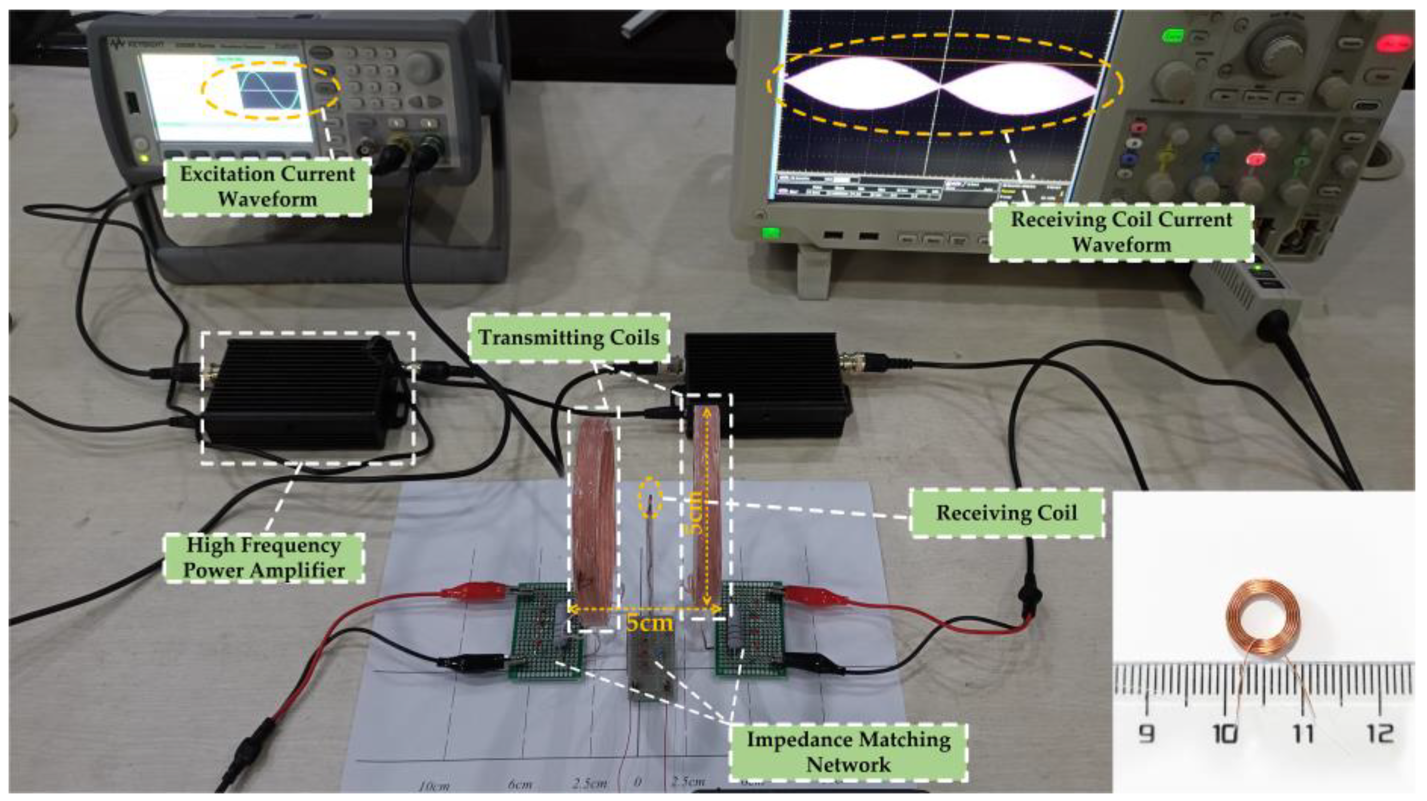
3.3. Experimental Study of the Current at the Receiving Coil

In order to verify whether the proposed WPT system can apply electrical stimulation of a sufficient intensity and suitable frequency to the target through TI, a real experimental platform with the same parameters as in the calculation was built for this paper, as shown in Figure 9. The corresponding schematic block diagram of the experimental prototype is shown in Figure 10. In the experiment, the energy input of the whole system was provided by a high-precision dual-channel signal generator. Since the power of the signal generator cannot reach the power requirement needed by the load, its output signal needed to be processed by a high-frequency power amplifier before it could be used as the excitation of the WPT system. The transmitting and receiving coils shown in the diagram were placed in air and fixed, and the three axes were kept aligned. Due to the hand winding, the actual inductance of transmitting coil 1 was 19 μH and the actual inductance of transmitting coil 2 was 18.94 μH. The resonance compensation capacitors were 5553 pF and 5570 pF, respectively. The parameters of the experimental test platform were set up as shown in Table 4, under the condition that the current amplitude applied to the two transmitting coils was guaranteed to be equal. Then, the oscilloscope’s reference side was connected to the signal generator’s ground side to measure and observe the current on the receiving coil.
The current waveform at the receiving coil displayed in the oscilloscope is shown in Figure 11. It can be seen that when the two transmitting coils are passed through to the differential frequency excitation, an envelope modulated current of 42.4 mA in amplitude and 10 Hz in frequency appears on the receiver side. The current range used for sciatic nerve stimulation is generally 0.2–0.8 mA [44]. The amplitude of the envelope modulated current in the receiving coil far exceeds the current density threshold for causing excitation of the sciatic nerve, which can meet the stimulation intensity of the sciatic nerve. At the same time, the frequency of the envelope modulated current is the frequency difference of the added excitation. Its value falls within the low-frequency range of the excitation of the sciatic nerve, which can induce the expected response of the sciatic nerve. Considering that this system has two transmitting coils, it can be calculated from Equation (12) that the transmitting power of the system is 400.98 mW for an excitation current amplitude of 0.2 A. As the resistance of the receiving coil is 1.09 Ω, the received power of the load resistor can be calculated to be approximately 0.98 mW at this point. Dividing the two powers calculates an efficiency of 0.244% for the load resistance at the system’s receiving end. This paper focuses on methodological and modeling innovations to achieve system size optimization, while ensuring the effective stimulation of the sciatic nerve. Further research will focus more on optimizing the efficiency and control functions. The above experimental results demonstrate the feasibility of the WPT system proposed in this paper to achieve a therapeutic electrical stimulation of the sciatic nerve through temporal interference.

4. Discussion

This paper proposes a novel temporally interfering WPT electrical stimulation system based on Helmholtz coils. After the proposed system’s theoretical derivation and model construction, the magnetic field distribution of the system after interference was obtained by numerical calculation. The results of the calculations proved the uniformity and stability of the magnetic field of the proposed system. The analysis shows that a non-physical dynamic adjustment of the stimulation location can be achieved by varying the magnitude of the emitter current. The current waveform of the receiving coil in the experimental results also verifies the feasibility of the proposed system to achieve effective stimulation of the sciatic nerve.
This system has two main advantages compared to conventional MCR-WPT units [12,13]. One uses the magnetic field superposition principle of temporal interference, which eliminates the need for a signal conversion device in the conventional MCR-WPT. Removing the battery-related components not only reduces the size of the implanted part but also eliminates concerns about the healthy life of the battery [7]. There is also no need to face the secondary trauma and financial burden of battery replacement [9]. The other one uses Helmholtz coils as the system’s transmitting coils. In contrast to the frequency tracking method and the optimal load tracking method [34,35], which are matched by real-time communication, this system can achieve a stable energy transmission without relying on communication between the transmitting and receiving coils by improving the coil structure. This ensures a maximum magnetic field uniformity so that the receiving coil receives a stable and continuous electrical stimulation. In contrast to SCS [4,47], this system concentrates the area of stimulation and has no additional effect on the non-target areas, making it possible to provide an efficient and focused treatment of the lesion. In addition, as this system does not involve the puncture of the spinal canal, it does not lead to several complications, such as cerebrospinal fluid leakage caused by SCS [48].
Calculating the stimulation location of a temporally interfering magnetic field in the human body needs to consider the actual electromagnetic characteristics of the human tissue parameters. However, due to the complexity of the actual human body model, the numerical calculation is computationally intensive. In order to facilitate the calculations, this paper assumes that the conductivity of the various tissues is uniform. This means that the difference between the lateral and longitudinal conductivity of the tissue is ignored, and the calculation is only performed in a cylindrical layered human model. The effectiveness of the electrical stimulation of the sciatic nerve in the treatment of CRPS–I has been clinically validated [4]. Given the devices’ variability, this stimulation method’s applicability in the clinical setting and its ability to achieve similar theoretical results needs to be further validated and explored in electrophysiological and animal experiments. The main idea of this paper is to treat CRPS–I using the electrical stimulation of the sciatic nerve. In fact, due to the similarity of treatment ideas, this system can also be applied to treating other types of neurological disorders. Varying the intensity and type of stimulus to produce the desired response from the target nerve enables the treatment of the disease at its source [49]. This makes it suitable for a wide range of applications.

5. Conclusions

The research of interventional treatment modalities is essential in reducing drug dependence in CRPS–I patients. The effectiveness of the CRPS–I foot pain modality through direct sciatic nerve stimulation has been clinically proven. This paper presents further research on the transmission stimulation system and proposes a novel wireless power transmission electrical stimulation system based on temporal interference. It provides a new solution to the miniaturization of implantable devices, easing the medication burden on patients.
According to the Bio–Savart law, this paper first solves for the magnetic flux density generated by the Helmholtz coils at any point in space. Combined with the MCR-WPT circuit model based on the Helmholtz coils’ structure, the transmission characteristics of the system were investigated by theoretical analysis. Analysis results showed that the Helmholtz transmitting coil could generate a stable magnetic field, and the receiving coil connected to the nerve electrode could obtain a good transmission efficiency. Finally, the uniformity of the magnetic field and the focus of the stimulation location were verified by a finite element analysis. The numerical calculations in free space showed a considerable area near the center of the Helmholtz coil axis where the magnetic flux density is very uniform. The magnetic field distribution remained largely undistorted even in subsequent numerical calculations with the addition of human tissue. The system’s uniform magnetic field in the working area provided the basis for an efficient and stable power transmission. A corresponding experimental platform was built to demonstrate that the proposed system could provide the energy required for electrical stimulation through WPT. The experimental results showed that the receiving coil generated an envelope-modulated current with an amplitude of 42.4 mA and a frequency of 10 Hz. The frequency and amplitude were in the range to cause a physiological response from the sciatic nerve, thus demonstrating the feasibility of the method to apply an effective stimulation to the target nerve. When the amplitude of the excitation current passed through the transmitting coils was 0.2 A, the magnitude of the received power of the system was calculated to be 0.98 mW. In fact, the system was not limited to the above power level. The transmitting coil structure and excitation current could be changed according to the target nerve’s needs to control the current’s intensity on the nerve electrodes, thus enabling a multi-scene electrical stimulation of the sciatic nerve. The peak of the envelope modulation amplitude | B A M | shifts as the amplitude of the two transmitting coil excitation signals changes, indicating that the temporal interference could achieve a non-physical dynamic adjustment of the stimulation location. Compared to conventional implantable electrical stimulation devices, the proposed electrical stimulation system has the advantage of being miniature and efficient. The alternating magnetic field induces a low-frequency current in the receiving coil, which stimulates the target nerve directly with the help of flexible electrodes implanted in the connected target nerve, thus providing a timely response to pain. This ensures a stable electrical stimulation while reducing the physical burden on the patient, making it a more versatile application.

Author Contributions

Conceptualization, X.Y. and P.G.; methodology, C.J.; software, C.J., P.G. and D.J.; validation, C.J. and P.G.; formal analysis, X.Y. and J.S.; resources C.J.; data curation, J.S., P.G. and Z.Y.; writing—original draft preparation, C.J.; writing—review and editing, P.G., Z.Y. and D.J.; visualization, C.J., P.G. and X.Y.; supervision, X.Y.; project administration, C.J., D.J. and J.S.; funding acquisition, X.Y. All authors have read and agreed to the published version of the manuscript.

Funding

This research was funded by the National Natural Science Foundation of China, grant number 52107236, and the Colleges and universities in Hebei province science and technology research project, grant number QN20211043.

Institutional Review Board Statement

Not applicable.

Informed Consent Statement

Not applicable.

Data Availability Statement

Not applicable.

Acknowledgments

All the authors sincerely thank the State Key Laboratory of Reliability and Intelligence of Electrical Equipment for its support.

Conflicts of Interest

The authors declare no conflict of interest.

References

  1. Lawson, E.F.; Castellanos, J.P. Complex Regional Pain Syndrome; Springer: Berlin/Heidelberg, Germany, 2021. [Google Scholar]
  2. Marinus, J.; Moseley, G.L.; Birklein, F.; Baron, R.; Maihöfner, C.; Kingery, W.S.; van Hilten, J.J. Clinical features and pathophysiology of complex regional pain syndrome. Lancet Neurol. 2011, 10, 637–648. [Google Scholar] [CrossRef]
  3. Eldufani, J.; Elahmer, N.; Blaise, G. A medical mystery of complex regional pain syndrome. Heliyon 2020, 6, e03329. [Google Scholar] [CrossRef] [PubMed]
  4. Buwembo, J.; Munson, R.; Rizvi, S.A.; Ijaz, A.; Gupta, S. Direct sciatic nerve electrical stimulation for complex regional pain syndrome Type 1. Neuromodulation Technol. Neural Interface 2021, 24, 1075–1082. [Google Scholar] [CrossRef] [PubMed]
  5. Mond, H.G.; Freitag, G. The cardiac implantable electronic device power source: Evolution and revolution. Pacing Clin. Electrophysiol. 2014, 37, 1728–1745. [Google Scholar] [CrossRef] [PubMed]
  6. Hu, C.; Ye, H.; Jain, G.; Schmidt, C. Remaining useful life assessment of lithium-ion batteries in implantable medical devices. J. Power Sources 2018, 375, 118–130. [Google Scholar] [CrossRef]
  7. Zhang, Y.; Mickle, A.D.; Gutruf, P.; McIlvried, L.A.; Guo, H.; Wu, Y.; Golden, J.P.; Xue, Y.; Grajales-Reyes, J.G.; Wang, X. Battery-free, fully implantable optofluidic cuff system for wireless optogenetic and pharmacological neuromodulation of peripheral nerves. Sci. Adv. 2019, 5, eaaw5296. [Google Scholar] [CrossRef] [PubMed]
  8. Li, N.; Yi, Z.; Ma, Y.; Xie, F.; Huang, Y.; Tian, Y.; Dong, X.; Liu, Y.; Shao, X.; Li, Y. Direct powering a real cardiac pacemaker by natural energy of a heartbeat. ACS Nano 2019, 13, 2822–2830. [Google Scholar] [CrossRef]
  9. Xu, G.; Yang, X.; Yang, Q.; Zhao, J.; Li, Y. Design on magnetic coupling resonance wireless energy transmission and monitoring system for implanted devices. IEEE Trans. Appl. Supercond. 2016, 26, 1–4. [Google Scholar] [CrossRef]
  10. Yang, X.; Zhao, J.; Xu, G.; Li, X.; Li, W.; Li, Y. The Experimental Research on a Small Size Magnetic Coupling Resonance Wireless Energy Transmission System. Trans. China Electrotech. Soc. 2016, 31, 13–17. [Google Scholar]
  11. Wright, J.P.; Mughrabi, I.T.; Wong, J.; Mathew, J.; Jayaprakash, N.; Crosfield, C.; Chang, E.H.; Chavan, S.S.; Tracey, K.J.; Pavlov, V.A. A fully implantable wireless bidirectional neuromodulation system for mice. Biosens. Bioelectron. 2022, 200, 113886. [Google Scholar] [CrossRef]
  12. Yoo, S.; Lee, J.; Joo, H.; Sunwoo, S.H.; Kim, S.; Kim, D.H. Wireless power transfer and telemetry for implantable bioelectronics. Adv. Healthc. Mater. 2021, 10, 2100614. [Google Scholar] [CrossRef] [PubMed]
  13. Haerinia, M.; Shadid, R. Wireless power transfer approaches for medical implants: A Review. Signals 2020, 1, 209–229. [Google Scholar] [CrossRef]
  14. Zhao, J.; Gao, Y. A 13.56 MHz wireless power transfer system with bidirectional data link and closed-loop power control for implantable neuromuscular stimulator. In Proceedings of the 2019 IEEE Asia-Pacific Microwave Conference (APMC), New Delhi, India, 10–13 December 2019; pp. 1002–1004. [Google Scholar]
  15. Zhang, X.; Meng, H.; Wei, B.; Wang, S.; Yang, Q. An improved three-coil wireless power link to increase spacing distance and power for magnetic resonant coupling system. EURASIP J. Wirel. Commun. Netw. 2018, 2018, 1–8. [Google Scholar] [CrossRef]
  16. Qiao, T.; Yang, X.; Lai, X.; Tang, H. Modeling and analysis of multi-coil magnetic resonance wireless power transfer systems. In Proceedings of the 2018 IEEE PELS Workshop on Emerging Technologies: Wireless Power Transfer (Wow), Montréal, QC, Canada, 3–7 June 2018; pp. 1–6. [Google Scholar]
  17. Hodgkin, A.L.; Huxley, A.F. A quantitative description of membrane current and its application to conduction and excitation in nerve. J. Physiol. 1952, 117, 500. [Google Scholar] [CrossRef]
  18. McIntyre, C.C.; Grill, W.M. Extracellular stimulation of central neurons: Influence of stimulus waveform and frequency on neuronal output. J. Neurophysiol. 2002, 88, 1592–1604. [Google Scholar] [CrossRef]
  19. Mortimer, J.T.; Bhadra, N. Fundamentals of electrical stimulation. In Neuromodulation; Elsevier: Amsterdam, The Netherlands, 2018; pp. 71–82. [Google Scholar]
  20. Luan, S.; Williams, I.; Nikolic, K.; Constandinou, T.G. Neuromodulation: Present and emerging methods. Front. Neuroeng. 2014, 7, 27. [Google Scholar] [CrossRef]
  21. Chapman, K.B.; Yousef, T.A.; Foster, A.; Stanton-Hicks, M.D.; van Helmond, N. Mechanisms for the clinical utility of low-frequency stimulation in neuromodulation of the dorsal root ganglion. Neuromodulation Technol. Neural Interface 2021, 24, 738–745. [Google Scholar] [CrossRef]
  22. Gabriel, S.; Lau, R.; Gabriel, C. The dielectric properties of biological tissues: III. Parametric models for the dielectric spectrum of tissues. Phys. Med. Biol. 1996, 41, 2271. [Google Scholar] [CrossRef]
  23. Barnes, F.S.; Greenebaum, B. Handbook of Biological Effects of Electromagnetic Fields-Two Volume Set; CRC Press: Boca Raton, FL, USA, 2018. [Google Scholar]
  24. Kurs, A.; Karalis, A.; Moffatt, R.; Joannopoulos, J.D.; Fisher, P.; Soljacic, M. Wireless power transfer via strongly coupled magnetic resonances. Science 2007, 317, 83–86. [Google Scholar] [CrossRef]
  25. Vinko, D.; Biondić, I.; Bilandžija, D. Impact of receiver power and coupling coefficient on resonant frequency in wireless power transfer system. In Proceedings of the 2019 International Symposium ELMAR, Zadar, Croatia, 23–25 September 2019; pp. 207–210. [Google Scholar]
  26. Zhang, P.; Saeedifard, M.; Onar, O.C.; Yang, Q.; Cai, C. A field enhancement integration design featuring misalignment tolerance for wireless EV charging using LCL topology. IEEE Trans. Power Electron. 2020, 36, 3852–3867. [Google Scholar] [CrossRef]
  27. Restrepo, A.F.; Franco, E.; Cadavid, H.; Pinedo, C.R. A comparative study of the magnetic field homogeneity for circular, square and equilateral triangular helmholtz coils. In Proceedings of the 2017 International Conference on Electrical, Electronics, Communication, Computer, and Optimization Techniques (ICEECCOT), Kunming, China, 8–10 December 2017; pp. 13–20. [Google Scholar]
  28. Bronaugh, E.L. Helmholtz coils for calibration of probes and sensors: Limits of magnetic field accuracy and uniformity. In Proceedings of the International Symposium on Electromagnetic Compatibility, Atlanta, GA, USA, 14–18 August 1995; pp. 72–76. [Google Scholar]
  29. García-Farieta, J.E.; Márquez, A.H. Exploring the magnetic field of Helmholtz and Maxwell coils: A computer-based approach exploiting the superposition principle. Rev. Bras. Ensino Fis. 2020, 42, 226434271. [Google Scholar] [CrossRef]
  30. Zhang, K.; Ren, X.; Liu, Y.; Hui, S.; Song, B. Analytical Solution and Experimental Validation of the Electromagnetic Field in an IPT System. Appl. Sci. 2019, 9, 1323. [Google Scholar] [CrossRef]
  31. Ma, Y.; Mao, Z.; Zhang, K. Optimization Design of Planar Circle Coil for Limited-Size Wireless Power Transfer System. Appl. Sci. 2022, 12, 2286. [Google Scholar] [CrossRef]
  32. Cai, C.; Wang, J.; Zhang, F.; Liu, X.; Zhang, P.; Zhou, Y.-G. A multichannel wireless UAV charging system with compact receivers for improving transmission stability and capacity. IEEE Syst. J. 2021, 16, 997–1008. [Google Scholar] [CrossRef]
  33. Cai, C.; Saeedifard, M.; Wang, J.; Zhang, P.; Zhao, J.; Hong, Y. A cost-effective segmented dynamic wireless charging system with stable efficiency and output power. IEEE Trans. Power Electron. 2022, 37, 8682–8700. [Google Scholar] [CrossRef]
  34. Yu, Z.; Shi-you, Y. Frequency tracking and controlling of wireless power transfer system. Electr. Mach. Control 2020, 24. [Google Scholar]
  35. Gao, X.; Deng, M.; Masaki, K. Tracking operator-based optimal load control for loosely coupled wireless power transfer systems. In Proceedings of the 2017 IEEE International Conference on Systems, Man, and Cybernetics (SMC), Banff, AB, Canada, 5–8 October 2017; pp. 2188–2193. [Google Scholar]
  36. Li, Y.; Jiang, S.; Liu, X.-L.; Li, Q.; Dong, W.-H.; Liu, J.-M.; Ni, X. Influences of coil radius on effective transfer distance in WPT system. IEEE Access 2019, 7, 125960–125968. [Google Scholar] [CrossRef]
  37. Li, K.; Zhao, H.; Lv, L.; Sun, Z.; Shi, Y.; Hua, Y.; Liu, Q. Influence of Coil Radius, Distance and Working Frequency on Efficiency in Two-Coil Magnetically Coupled Resonant Wireless Power Transmission System. In Proceedings of the 2019 IEEE International Conference on Mechatronics and Automation (ICMA), Tianjin, China, 4–7 August 2019; pp. 2121–2125. [Google Scholar]
  38. Qingdong, C.; Junping, W. Simulation and Analysis of Magnetostatic Field based on COMSOL Software. Phys. Exp. Coll. 2018, 31, 88–91. [Google Scholar]
  39. Grossman, N.; Bono, D.; Dedic, N.; Kodandaramaiah, S.B.; Rudenko, A.; Suk, H.-J.; Cassara, A.M.; Neufeld, E.; Kuster, N.; Tsai, L.-H. Noninvasive deep brain stimulation via temporally interfering electric fields. Cell 2017, 169, 1029–1041.e16. [Google Scholar] [CrossRef]
  40. Grossman, N. Modulation without surgical intervention. Science 2018, 361, 461–462. [Google Scholar] [CrossRef]
  41. Sorkhabi, M.M.; Wendt, K.; Denison, T. Temporally interfering TMS: Focal and dynamic stimulation location. In Proceedings of the 2020 42nd Annual International Conference of the IEEE Engineering in Medicine & Biology Society (EMBC), Montréal, QC, Canada, 20–24 July 2020; pp. 3537–3543. [Google Scholar]
  42. Kim, J.; Jeong, J. Range-adaptive wireless power transfer using multiloop and tunable matching techniques. IEEE Trans. Ind. Electron. 2015, 62, 6233–6241. [Google Scholar] [CrossRef]
  43. Truong, B.D.; Andersen, E.; Casados, C.; Roundy, S. Magnetoelectric wireless power transfer for biomedical implants: Effects of non-uniform magnetic field, alignment and orientation. Sens. Actuators A 2020, 316, 112269. [Google Scholar] [CrossRef]
  44. Liu, X.; Liu, Z.; Huang, S. Literature analysis of electroacupuncture stimulation index on the treatment of sciatica. Zhongguo Zhenjiu 2009, 29, 1026–1028. [Google Scholar]
  45. “Technical and Operating Parameters and Spectrum Use for Short-Range Radiocommunication Devices” in International Telecommunication Union. Available online: www.itu.int/pub/R-REP-SM.2153-2-2011 (accessed on 16 May 2022).
  46. ETSI EN 302 536 V2.2.1 European Telecommunications Standards Institute. 2017. Available online: https://www.etsi.org/deliver/etsi_en/302500_302599/302536/02.01.01_60/en_302536v020101p.pdf (accessed on 17 May 2022).
  47. Donas, K.P.; Schulte, S.; Ktenidis, K.; Horsch, S. The role of epidural spinal cord stimulation in the treatment of Buerger’s disease. J. Vasc. Surg. 2005, 41, 830–836. [Google Scholar] [CrossRef] [PubMed]
  48. Bendersky, D.; Yampolsky, C. Is spinal cord stimulation safe? A review of its complications. World Neurosurg. 2014, 82, 1359–1368. [Google Scholar] [CrossRef] [PubMed]
  49. Grill, W.M. Temporal pattern of electrical stimulation is a new dimension of therapeutic innovation. Curr. Opin. Biomed. Eng. 2018, 8, 1–6. [Google Scholar] [CrossRef]
Figure 1. Spatial structure of the Helmholtz coils.
Applsci 12 09832 g001
Figure 2. Equivalent circuit model for Helmholtz coils WPT.
Applsci 12 09832 g002
Figure 3. Waveform of the low-frequency envelope modulated signal produced by temporal interference.
Applsci 12 09832 g003
Figure 4. Helmholtz coils–based model for a temporally interfering WPT system.
Applsci 12 09832 g004
Figure 5. The distribution of the magnetic flux density in free space in the y o z plane.
Applsci 12 09832 g005
Figure 6. Simplified multi-layered human tissue model.
Applsci 12 09832 g006
Figure 7. Magnetic field distribution after the addition of multi–layer human tissue.
Applsci 12 09832 g007
Figure 8. Magnetic field distribution in the x o y plane in a multi–layered human tissue model.
Applsci 12 09832 g008
Figure 9. Experimental platform and receiving coil for Helmholtz coils wireless power transfer system.
Applsci 12 09832 g009
Figure 10. Block diagram of the experimental prototype.
Applsci 12 09832 g010
Figure 11. Current waveform at the receiving coil.
Applsci 12 09832 g011
Table 1. Comparison of the different power supply methods for implantable devices.
Continuity of
Power Supply
Battery
Units
Signal Processing ModulesCoupling Type
Battery PoweredConsumedYesYesNone
Conventional Resonant WPTSustainabilityYesYesMagnetically coupled
Temporal Interference WPTSustainabilityNoneNoneMagnetically coupled
Table 2. The symbols and values of the parameters for the numerical calculation in free space.
CoilsParametersSymbolValue
Transmitting
Coils
Number of turns N 1 , N 2 10
Radius R 1 , R 2 5 cm
Inductance L 1 , L 2 18.12 μH
Capacitances C 1 , C 2 5823 pF
Distance between coils h 5 cm
Receiving
Coil
Wire diameter d 0.2 mm
Outer diameter D O T 10 mm
Inner diameter D I N 6 mm
Inductance L 3 19.93 μH
Capacitances C 3 5393 pF
Table 3. The parameters of the human tissue model in numerical calculations.
SkinFatMuscle
Electrical Conductivity (S/m)0.130.0450.5
Thickness (mm)2416
Table 4. The equipment parameters in experimental tests.
Experimental EquipmentParametersValue
Transmitting Coil 1Current Frequency490 kHz
Current Amplitude0.2 A
Resistances10 Ω
Inductance19 μH
Capacitances5553 pF
Transmitting Coil 2Current Frequency490 kHz + 10 Hz
Current Amplitude0.2 A
Resistances10 Ω
Inductance18.94 μH
Capacitances5570 pF
Receiving CoilResistances1.09 Ω
Current Frequency10 Hz
Current Amplitude42.4 mA
Publisher’s Note: MDPI stays neutral with regard to jurisdictional claims in published maps and institutional affiliations.

