


Experimental Study and Modelling on the Structural Response of Fiber Reinforced Concrete Beams

 ,
,  , , and
Abstract
:1. Introduction
2. Materials and Methods
2.1. Concrete Mix Materials
- Portland cement CEM I 42.5N.
- Sikament® 56, a third generation (polycarboxylate based) superplasticizer admixture. It was used to provide flowability of the mix and dispersion of microparticles. Basic properties: light yellow and highly flowable liquid, density—1.08 ± 0.02 kg/dm3, pH—4.5 ± 1, solid content—37 ± 1%. Recommended dosage: in the range of 0.1–2.0 % by weight of cement.
- Stabilizer AkzoNobel Cembinder 50. A commercial colloidal nano-silica product Cembinder 50 was used. Nano-silica is a new generation of reactive silicon dioxide admixtures. Its high reactivity is explained with chemical purity and extremely high specific surface (>30,000 m2/kg) and particle size <100 nm. The size of the silica fume particle corresponds up to 1000 nano-silica particles and, comparing with the size of cement particles, one cement particle corresponds to approximately one billion of nano-silica particles. This determines high chemical reactivity of the admixture and its accelerated effect on the cement hydration.
- Coarse aggregates. Crushed limestone (fractions 2/6 mm) was used as a coarse aggregate. The shape of the rough aggregate has a significant influence on the workability of a concrete mix, because water quantity depends on the type of aggregate, particle size distribution, the shape and texture of grains and the quantity of fines.
- Fine aggregate Saulkalne. Fine aggregate of three grades was used: washed quartz-based sand, fractions 0/0.4 (fine), 0/1 (medium), and 0.4/1.2 mm (coarse).
- Silica fume or Micro-silica, a very fine pozzolanic material composed of amorphous silica produced by electric arc furnaces as a by-product of production of elemental silicon or ferro silicon alloy. Addition of micro silica to cementitious systems can improve the strength by controlling the structure of C-S-H. Silica fume is high-purity amorphous silicon dioxide with >92% SiO2 content. Silica fume particles are characterized by spherical shape and diameter in the range of 0.05–0.5 µm or 50–500 nm.
- Fly ash. This pozzolanic admixture is produced as a by-product of coal combustion in the power plants, it is usually collected with electrostatic filters. Good quality conventional fly ash offers such advantages as improvement of concrete workability properties, improvement of structural tightness, reduction of hydration heat, increase of resistance to chemical aggression, participation of ash in cement binding reactions, higher resistance of concrete over long period and reduction of production costs of the concrete mixture. Commercially used fly ash with the cumulative content of oxides SiO2 + Al2O3 + Fe2O3 was equal to 84.7% thereof. It was classified as class F fly ash in accordance with ASTM C618 [49].
2.2. Fibers
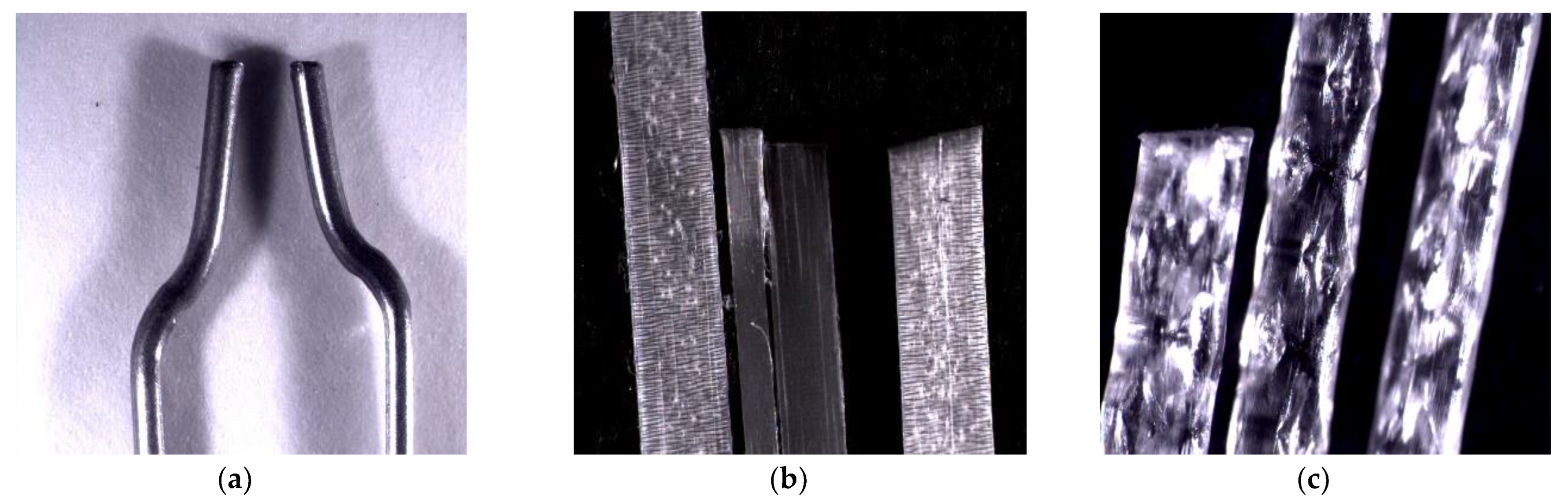
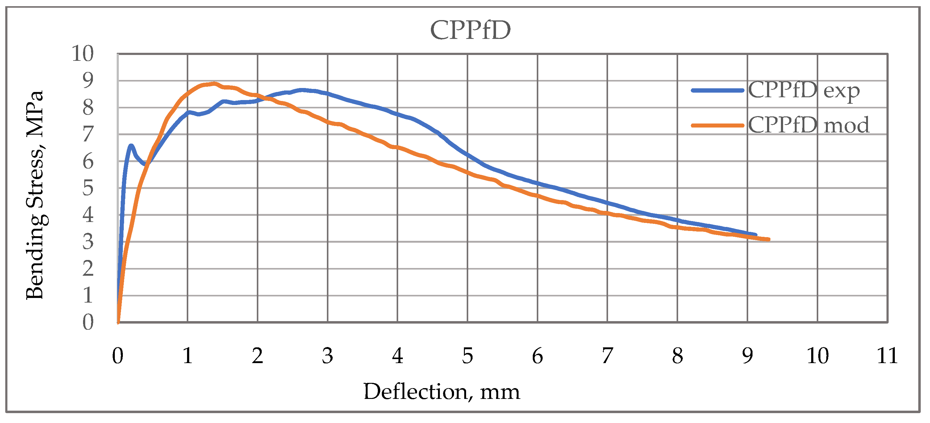
- PP fibers: Durus PP 45 mm long fibers were used in the third FRC group, employing the opportunity to compare the results of the samples with the same type of fiber, but of different fiber length, produced by a different company, and ultimately compare them with the samples made using different types of fiber. Figure 1c and Table 1 provide the illustration and the properties of this fiber, respectively.
2.3. Sample Preparation
2.3.1. Concrete Mixing
2.3.2. Fiber Quantity
2.3.3. Specimen Sizes
2.4. Testing Technological Properties
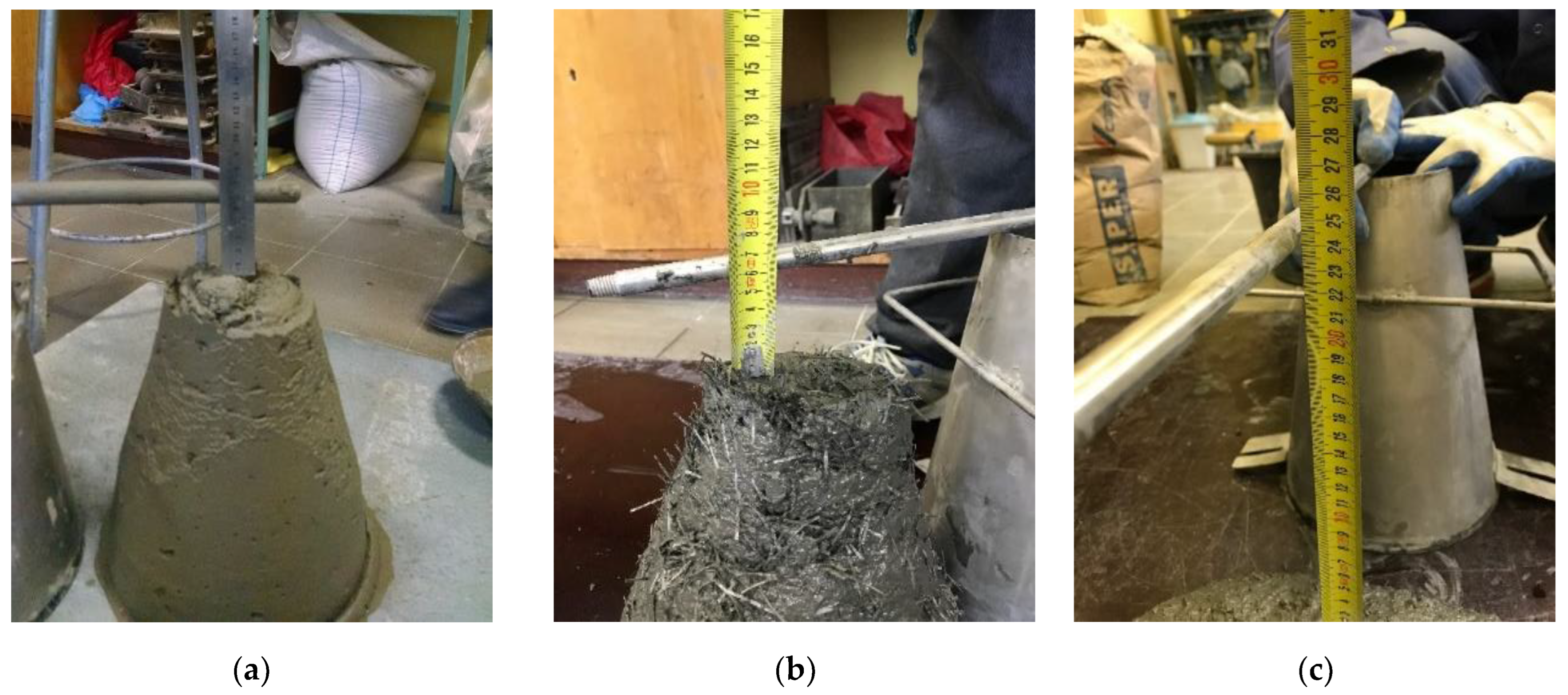
Sieve Segregation Test
2.5. Testing Structural Properties
2.5.1. Compressive Testing Procedure and Strength of Concrete Cube
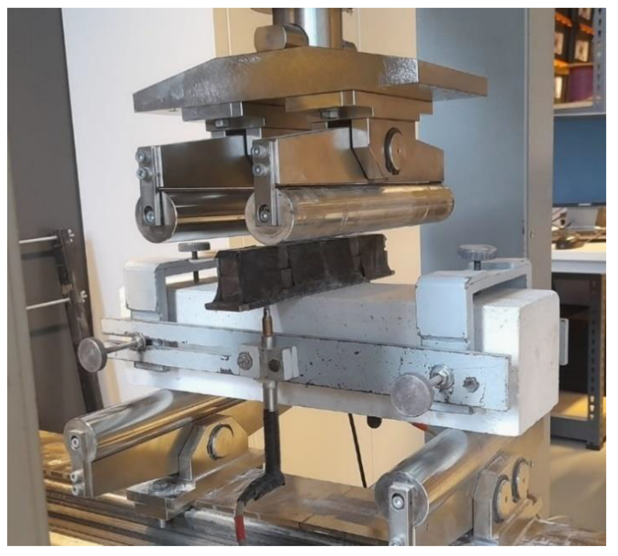
2.5.2. Four Point Bending Testing Procedure
3. Experimental Results and Discussion
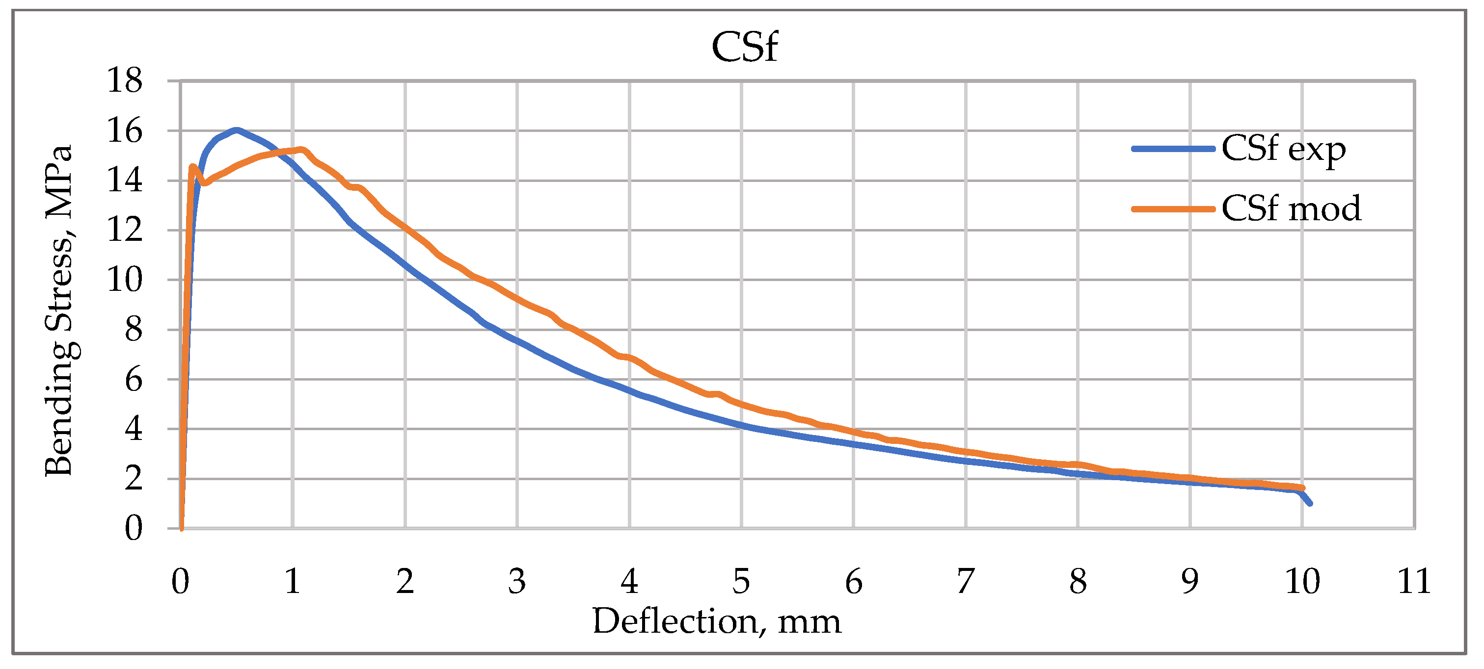
- The phase of linearly elastic deformation of concrete matrix, indicating the linear deformation from 0.02 mm to 0.25 mm with no formation of visible cracks and without significant load in the fibres.
- The phase of critical load, showing the linear deformation of concrete matrix from 0.25 mm to 0.5 mm.
- The phase of fibre pull-out, indicating the formation of macro-cracks with the opening width from 0.1 mm to 0.35 mm. The tension force transfer resulted in the resistance to crack propagation, imparting the strength, i.e., the fibres were bridging the cracks, collecting tension forces at the edges of the cracks. The results obtained correlate with the data from the related research [60,61]. The comparison of experimental data of the steel fibre pull-out test and numerical simulation results was carried out. The third phase corresponds to the growth of delamination along the fibre and matrix interface until full debonding of the fibres (crossing micro-cracks), followed by fibre sliding out of the matrix with friction, and partial plastic deformation of the fibres [62,63].
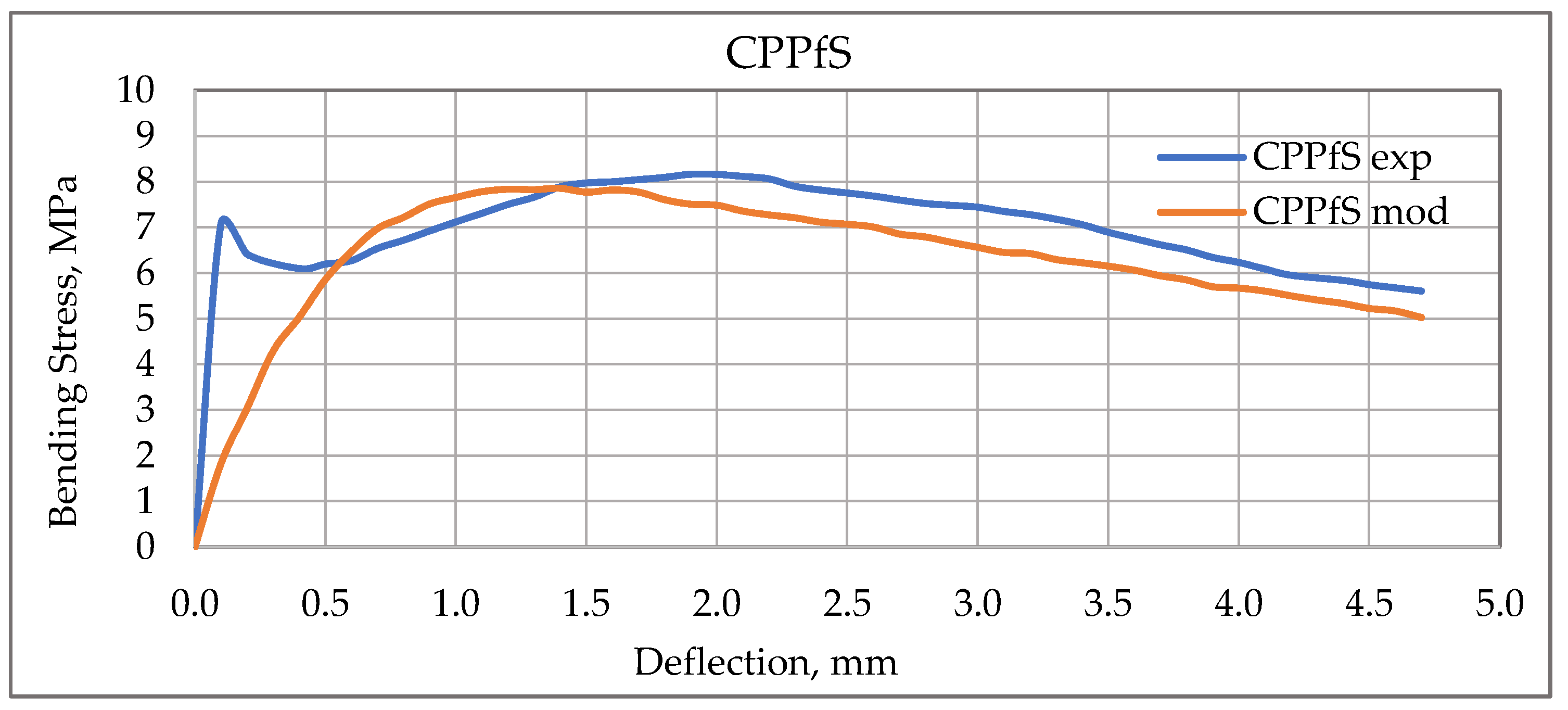
- The phase of linearly elastic deformation indicating the linear deformation from 0.01 mm to 0.15 mm with no formation of visible cracks and without significant load in the fibres.
- The phase of critical load showing the linear deformation from 0.15 mm to 0.2 mm.
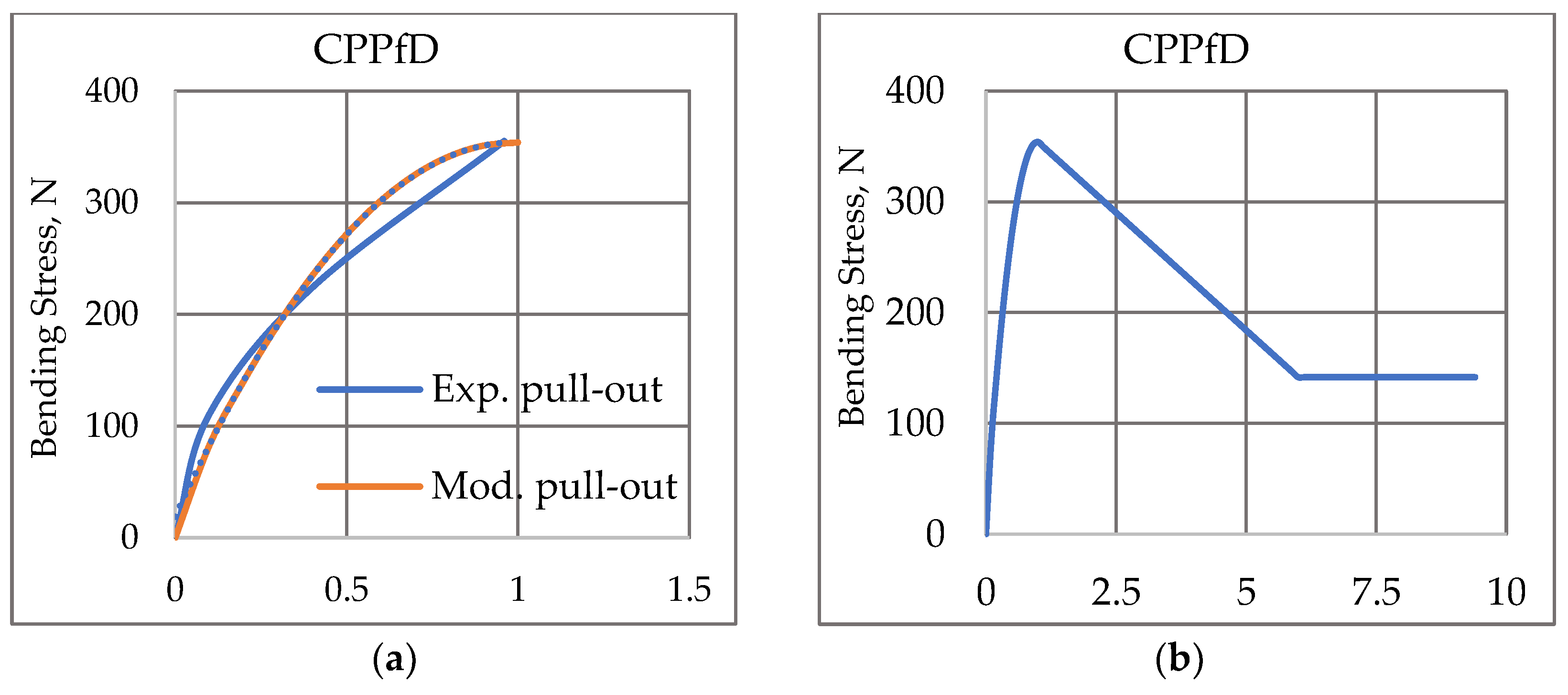
- The phase of elastic deformation provided by the PP fibres, increasing the load bearing capacity of the members and resisting the loads. The change in the deformation from 0.2 mm to 2 mm during the fibre pull-out or change indicating the formation of cracks with the opening width from 0.1 mm to 0.35 mm was recorded. The tension force transfer resulted in the increased resistance to crack propagation, imparting the strength to the prism members.
- It is necessary to take care about the concrete mix during addition of the fibres to make the mix homogeneous, for example, by adding the fibres in layers. Proper finishing of the top layer is necessary, making sure no marks of fibres are left on the sidewalks.
- Fibre pull-out is a process dependant on how far each fibre is pulled out. Some fibres are more effective in the beginning, when deflection of structural elements is small (deformation of the structural member with a more sophisticated geometry), some—at the final stage, when many cracks in the material are formed. Since the PP fibres are smooth and do not have a proper grip to the surfaces in the concrete mix, they propagate all over the mix, which might cause problems due to accumulation of several fibres in some places. This may result in value change. Homogeneous fibre distribution in the material volume is important for the decrease of the scatter of load bearing results.
- The non-corrosive nature is another important benefit of the PP fibres. It is rarely observed in the steel fibres if they are not property coated with resins. Therefore, care must be taken in this regard if it is planned to create longer spans for any construction.
4. Modelling
Modelling Results
5. Conclusions
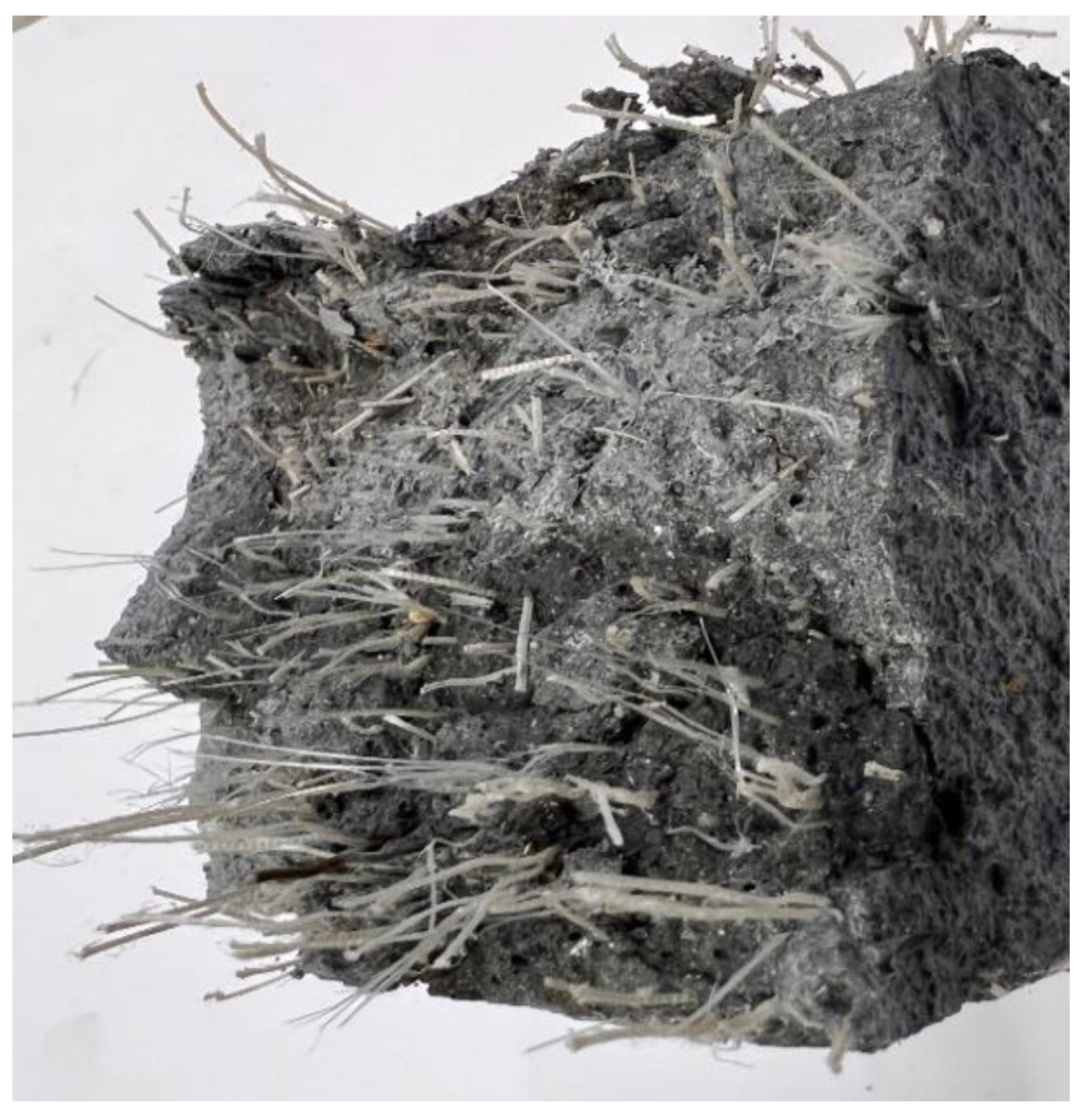
- Macro-crack opening in the concrete with steel fibers is possible to describe by fibers pull-out process. Macro-crack opening in the concrete with polymer (PP) fibers is happening with partial fibers breaking, pulling out of fibers oriented under smaller angles and partial rotation of pulled out fiber part. This not-obvious crack opening mechanism needs additional investigation.
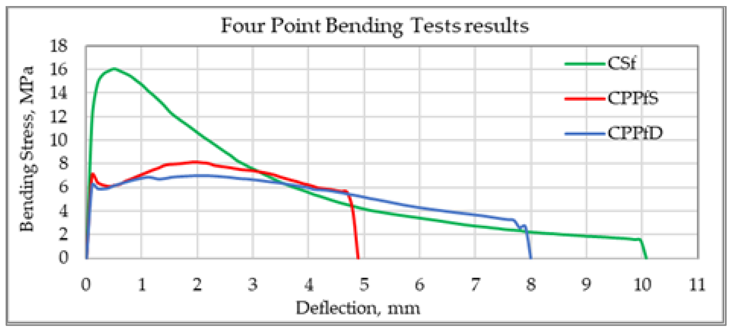
- The four-point bending tests of FRC prisms allow to analyze and predict load bearing potential of the FRC mix at different stages of damage accumulation in the material. Load bearing capacity of FRC is changing during cracking, along with the increase of the value of deflection of the damaged beam. Cracked beams with opened cracks, with polymer fibers start carrying higher load compared to the samples with the steel fibers.
- Hooks (or geometry change) on the ends of steel fibers play an important role in ensuring the bending strength.
- Failure mechanism in FRC with metal and polymer fibres may be different. Comparing them is possible to recognize the micromechanics of processes happening on the stage of crack opening. Steel FRC load bearing on this stage is characterized by intensive fibers, that are bridging the macro-crack, pulling out process. In the situation with FRC having PP fibres Duru’s micromechanics of load bearing is different.
Author Contributions
Funding
Institutional Review Board Statement
Informed Consent Statement
Data Availability Statement
Conflicts of Interest
References
- Gagg, C.R. Cement and concrete as an engineering material: An historic appraisal and case study analysis. Eng. Fail. Anal. 2014. [Google Scholar] [CrossRef]
- Jacobs, J.P. (Ed.) Sustainable Benefits of Concrete Structures; European Concrete Platform ASBL: Brussels, Belgium, 2009; pp. 2–40. [Google Scholar]
- Lasenko, I.; Grauda, D.; Butkauskas, D.; Sanchaniya, J.V.; Viluma-Gudmona, A.; Lusis, V. Testing the Physical and Mechanical Properties of Polyacrylonitrile Nanofibers Reinforced with Succinite and Silicon Dioxide Nanoparticles. Textiles 2022, 2, 9. [Google Scholar] [CrossRef]
- Viluma-Gudmona, A.; Lasenko, I.; Vrajlal Sanchaniya, J.; Abdelhadi, B. The amber nano fibers development prospects to expand the capabilites of textile 3D printing in the general process of fabrication methods. In Proceedings of the International Scientific Conference (Latvia), Engineering for Rural Development, Jelgava, Latvia, 26–28 May 2021; pp. 248–257. [Google Scholar] [CrossRef]
- Grauda, D.; Bumbure, L.; Lyashenko, I.; Katashev, A.; Dekhtyar, Y.; Rashal, I. Amber Particles as Living Plant Cell Markers in Flow Cytometry / Dzintara Daļiņas Kā Dzīvu Augu Šūnu Marķieri Plūsmas Citometrijā. Proc. Latv. Acad. Sci. Sect. B Nat. Exact. Appl. Sci. 2015, 69, 77–81. [Google Scholar] [CrossRef]
- Viluma-Gudmona, A.; Lasenko, I.; Sanchaniya, J.V.; Podgornovs, A. Electro-resistant biotextile development based on fiber reinforcement with nano particles. In Proceedings of the International Scientific Conference (Latvia), Engineering for Rural Development, Jelgava, Latvia, 26–28 May 2021; pp. 804–812. [Google Scholar] [CrossRef]
- Lasenko, I.; Gaidukovs, S.; Rombovska, J. Manufacturing of amber particles suitable for composite fibre melt spinning. Proc. Latv. Acad. Sci. Sect. B Nat. Exact. Appl. Sci. 2016, 70, 51–57. [Google Scholar] [CrossRef]
- Corradi, M. Concrete for the construction industry of tomorrow. In Measuring, Monitoring and Modeling Concrete Properties; Springer: Dordrecht, The Netherlands, 2007. [Google Scholar] [CrossRef]
- Sahmenko, G.; Rucevskis, S.; Lusis, V.; Dembovska, L.; Korjakins, A.; Annamaneni, K.K.; Bajare, D. The study of the combined effect of fly ash, silica fume, colloidal silica and superplasticizer on high performance cement composite applying mix optimization method. Mech. Compos. Mater. 2022, unpublished manuscript. [Google Scholar]
- Birzniece, I.M.; Cizevska, A.; Goljandin, D.; Lusis, V. Comparison of Electrical Conductivity of Cement Composite Materials. In Proceedings of the 7th World Multidisciplinary Civil Engineering-Architecture-Urban Planning Symposium—WMCAUS, Prague, Czech Republic, 5–9 September 2022; pp. 1–10, unpublished work. [Google Scholar]
- Duy, N.P.; Anh, V.N.; Hiep, D.V.; Anh, N.M.T. Strength of concrete columns reinforced with Glass fiber reinforced polymer. Mag. Civ. Eng. 2021, 101, 10108. [Google Scholar] [CrossRef]
- Kulakov, V.L.; Terrasi, G.P.; Arnautov, A.K.; Portnov, G.G.; Kovalov, A.O. Fastening of a High-Strength Composite Rod with a Splitted and Wedged End in a Potted Anchor 2. Finite-Element Analysis. Mech. Compos. Mater. 2014, 50, 39–50. [Google Scholar] [CrossRef]
- Kovalovs, A.; Akishin, P.; Chate, A. Detection Prestress Loss in Prestressed Concrete Slab using Modal Analysis. IOP Conf. Ser. Mater. Sci. Eng. 2019, 471, 102015. [Google Scholar] [CrossRef]
- Ramanathan, S.; Benzecry, V.; Suraneni, P.; Nanni, A. Condition assessment of concrete and glass fiber reinforced polymer (GFRP) rebar after 18 years of service life. Case Stud. Constr. Mater. 2021, 14, e00494. [Google Scholar] [CrossRef]
- Gluhih, S.; Kovalov, A.; Tishkunov, A.; Akishin, P.; Chate, A.; Auzins, E.; Kalnins, M. Identification of the elastic modulus of polymeric materials by using thin-walled cylindrical specimens. Mech. Compos. Mater. 2012, 48, 57–64. [Google Scholar] [CrossRef]
- Lusis, V.; Annamaneni, K.K.; Krasnikovs, A. Concrete Reinforced by Hybrid Mix of Short Fibers under Bending. Fibers 2022, 10, 11. [Google Scholar] [CrossRef]
- Ng, T.S.; Nyan, T.S.H. Structural Application of Steel Fibres Reinforced Concrete with and Without Conventional Reinforcement. New Zeal. Concr. Ind. 2017, 3101. [Google Scholar]
- Abolmaali, A.; Mikhaylova, A.; Wilson, A.; Lundy, J. Performance of steel fiber-reinforced concrete pipes. Transp. Res. Rec. 2012, 1, 168–177. [Google Scholar] [CrossRef]
- Lusis, V.; Harjkova, G.; Macanovskis, A.; Kononova, O.; Krasnikovs, A. Fracture of layered fiberconcrete with non-homogeneous fiber distribution. In Proceedings of the 12th International Scientific Conference on Engineering for Rural Development 2013, Jelgava, Latvia, 23–24 May 2013; pp. 273–277. [Google Scholar]
- Sikarskas, D.; Antonovič, V.; Malaiškienė, J.; Boris, R.; Stonys, R.; Šahmenko, G. Modification of the Structure and Properties of Lightweight Cement Composite with PVA Fibers. Materials 2021, 14, 5983. [Google Scholar] [CrossRef]
- Khabaz, A. Analysis of sliding mechanism of straight steel fibers in concrete and determine the effect of friction. Arch. Civ. Mech. Eng. 2017, 17, 599–608. [Google Scholar] [CrossRef]
- Hussain, I.; Ali, B.; Akhtar, T.; Jameel, M.S.; Raza, S.S. Comparison of mechanical properties of concrete and design thickness of pavement with different types of fiber-reinforcements (steel, glass, and polypropylene). Case Stud. Constr. Mater. 2020, 13, e00429. [Google Scholar] [CrossRef]
- Singhal, K.; Mishra, S.; Kumar, B. A study of curling in rib-knit constructions. J. Text. Inst. 2021, 112, 666–675. [Google Scholar] [CrossRef]
- Macanovskis, A.; Lukasenoks, A.; Krasnikovs, A.; Stonys, R.; Lusis, V. Composite Fibers in Concretes with Various Strengths. ACI Mater. J. 2018, 115, 647–652. [Google Scholar] [CrossRef]
- Sarkar, A.; Hajihosseini, M. The effect of basalt fibre on the mechanical performance of concrete pavement. Road Mater. Pavement Des. 2020, 21, 1726–1737. [Google Scholar] [CrossRef]
- Shanbara, H.K.; Ruddock, F.; Atherton, W. A laboratory study of high-performance cold mix asphalt mixtures reinforced with natural and synthetic fibres. Constr. Build. Mater. 2018, 172, 166–175. [Google Scholar] [CrossRef]
- Ali, B.; Qureshi, L.A.; Kurda, R. Environmental and economic benefits of steel, glass, and polypropylene fiber reinforced cement composite application in jointed plain concrete pavement. Compos. Commun. 2020, 22, 100437. [Google Scholar] [CrossRef]
- Benaoum, F.; Khelil, F.; Benhamena, A. Numerical analysis of reinforced concrete beams pre-cracked reinforced by composite materials. Frat. Integrita Strutt. 2020, 14, 282–296. [Google Scholar] [CrossRef]
- Elbehiry, A.; Elnawawy, O.; Kassem, M.; Zaher, A.; Mostafa, M. FEM evaluation of reinforced concrete beams by hybrid and banana fiber bars (BFB). Case Stud. Constr. Mater. 2021, 14, e00479. [Google Scholar] [CrossRef]
- Bleive, L.L.; Lusis, V. Experimental study and numerical modelling for flexural capacity of FRC structural elements. Environ. Technol. Resour. Proc. Int. Sci. Pract. Conf. 2021, 3, 30–35. [Google Scholar] [CrossRef]
- Krasnikovs, A.; Kononova, O.; Machanovskis, A.; Zaharevskis, V.; Akishins, P.; Ruchevskis, S. Characterization of mechanical properties by inverse technique for composite reinforced by knitted fabric. Part 2. Experimental evaluation of mechanical properties by frequency eigenvalues method. J. Vibroeng. 2012, 14, 691–698. [Google Scholar]
- Blazy, J.; Blazy, R.; Drobiec, Ł. Glass Fiber Reinforced Concrete as a Durable and Enhanced Material for Structural and Architectural Elements in Smart City—A Review. Materials 2022, 15, 2754. [Google Scholar] [CrossRef]
- Lasenko, I. Mechanical properties of nanocomposite reinforced with the PA6 electro spun nanofiber. Multidiscip. Digit. Publ. Inst. 2022, unpublished work. [Google Scholar]
- Monazami, M.; Gupta, R. Influence of Polypropylene, Carbon and Hybrid Coated Fiber on the Interfacial Microstructure Development of Cementitious Composites. Fibers 2021, 9, 65. [Google Scholar] [CrossRef]
- Blazy, J. Case Studies in Construction Materials Polypropylene fiber reinforced concrete and its application in creating architectural forms of public spaces. Case Stud. Constr. Mater. 2021, 14. [Google Scholar] [CrossRef]
- Acosta-Calderon, S.; Gordillo-Silva, P.; García-Troncoso, N.; Bompa, D.V.; Flores-Rada, J. Comparative Evaluation of Sisal and Polypropylene Fiber Reinforced Concrete Properties. Fibers 2022, 10, 31. [Google Scholar] [CrossRef]
- Lesovik, V.; Fediuk, R.; Amran, M.; Alaskhanov, A.; Volodchenko, A.; Murali, G.; Uvarov, V.; Elistratkin, M. 3D-Printed Mortars with Combined Steel and Polypropylene Fibers. Fibers 2021, 9, 79. [Google Scholar] [CrossRef]
- Tawfik, M.; El-said, A.; Deifalla, A.; Awad, A. Mechanical Properties of Hybrid Steel-Polypropylene Fiber Reinforced High Strength Concrete Exposed to Various Temperatures. Fibers 2022, 10, 53. [Google Scholar] [CrossRef]
- Feng, X.; Gong, B.; Tang, C.; Zhao, T. Study on the non-linear deformation and failure characteristics of EPS concrete based on CT-scanned structure modelling and cloud computing. Eng. Fract. Mech. 2022, 261, 108214. [Google Scholar] [CrossRef]
- Watts, M.J.; Amin, A.; Gilbert, R.I. Time-dependent deformation and cracking behaviour of FRC beams. Eng. Struct. 2022, 268, 114741. [Google Scholar] [CrossRef]
- Zhang, P.; Han, S.; Ng, S.; Wang, X.H. Fiber-Reinforced Concrete with Application in Civil Engineering. Adv. Civ. Eng. 2018, 2018. [Google Scholar] [CrossRef]
- Kasu, S.R.; Mitra, N.; Muppireddy, A.R. Influence of polyester microfiber reinforcement on flexural fatigue characteristics of concrete. Road Mater. Pavement Des. 2020, 22, 2866–2882. [Google Scholar] [CrossRef]
- Annamaneni, K.K.; Dobariya, B.V.; Krasnikovs, A. Concrete, reinforced by carbon fibre composite structure, load bearing capacity during cracking. Environ. Technol. Resour. Proc. Int. Sci. Pract. Conf. 2021, 2, 232–237. [Google Scholar] [CrossRef]
- Herrmann, H.; Goidyk, O.; Braunbrück, A. Influence of the Flow of Self-Compacting Steel Fiber Reinforced Concrete on the Fiber Orientations, a Report on Work in Progress. In Part of the Advanced Structured Materials Book Series (STRUCTMAT, Volume 95); Springer: Cham, Switzerland, 2019; pp. 97–110. [Google Scholar] [CrossRef]
- Herrmann, H.; Goidyk, O.; Naar, H.; Tuisk, T.; Braunbrück, A. The influence of fibre orientation in self-compacting concrete on 4-point bending strength. Proc. Est. Acad. Sci. 2019, 68, 337–346. [Google Scholar] [CrossRef]
- Krasnikovs, A.; Zaharevskis, V.; Kononova, O.; Lusis, V.; Galushchak, A.; Zaleskis, E. Fiber concrete properties control by fibers motion investigation in fresh concrete during casting. In Proceedings of the 8th International DAAAM Baltic Conference “Industrial engineering”, Tallinn, Estonia, 19–21 April 2012; pp. 657–662. [Google Scholar]
- Bao, C.; Bi, J.H.; Xu, D.; Guan, J.; Cheng, W.X. Numerical simulation of the distribution and orientation of steel fibres in SCC. Mag. Concr. Res. 2020, 72, 1102–1111. [Google Scholar] [CrossRef]
- Herrmann, H.; Braunbrück, A.; Tuisk, T.; Goidyk, O.; Naar, H. An Initial Report on the Effect of the Fiber Orientation on the Fracture Behavior of Steel Fiber Reinforced Self-Compacting Concrete. Adv. Struct. Mater. 2019, 95, 33–50. [Google Scholar] [CrossRef]
- ASTM C618; Standard Specification for Coal Fly Ash and Raw or Calcined Natural Pozzolan for Use in Concrete. American Society of Testing and Materials: West Conshohocken, PA, USA, 2005. [CrossRef]
- EN 206-1; Concrete-Part 1: Specification, Performance, Production and Conformity. European Committee for Standardization (CEN): Brussel, Belgium, 2000.
- Properties and Applications of Fiber Reinforced Concrete. JKAU Eng. Sci 1410, 2, 49–63.
- Criado, M.; Palomo, A.; Fernández-Jiménez, A. Alkali activation of fly ashes. Part 1: Effect of curing conditions on the carbonation of the reaction products. Fuel 2005, 84, 2048–2054. [Google Scholar] [CrossRef]
- Sahmaran, M.; Yurtseven, A.; Ozgur Yaman, I. Workability of hybrid fiber reinforced self-compacting concrete. Build. Environ. 2005, 40, 1672–1677. [Google Scholar] [CrossRef]
- Sonebi, M. Evaluation of the Segregation Resistance of Fresh Self-Compacting Concrete using different test methods. In Proceedings of the SCC’2005-China—1st International Symposium on Design, Performance and Use of Self-Consolidating Concrete, Changsha, China, 26–28 May 2005; RILEM Publications SARL: Marne la Vallée, France, 2005; pp. 301–308. [Google Scholar] [CrossRef]
- Ogunbayo, B.; Aigbavboa, C. Experimental Investigation of Concrete Block Walls Compressive Strength Using a Non-destructive Test. In Collaboration and Integration in Construction, Engineering, Management and Technology; Springer: Cham, Switzerland, 2021; pp. 393–397. [Google Scholar] [CrossRef]
- Kruschwitz, S.; Oesch, T.; Mielentz, F.; Meinel, D.; Spyridis, P. Non-Destructive Multi-Method Assessment of Steel Fiber Orientation in Concrete. Appl. Sci. 2022, 12, 697. [Google Scholar] [CrossRef]
- Mellios, N.; Oesch, T.; Spyridis, P. Finite element modelling of UHPC under pulsating load using X-ray computed tomography based fiber distributions. Mater. Struct. 2022, 55, 1. [Google Scholar] [CrossRef]
- EN 12390-3:2019; Testing Hardened Concrete–Part 3: Compressive Strength of Test Specimens. European Committee for Standardization: Brussels, Belgium, 2019.
- LVS 156-1:2017; Concrete. Latvian National Annex to the European Standard EN 206:2013 Concrete. Technical Regulations, Execution of Works, Production and Conformity; Cabinet Regulation No 156 “Procedures for the Market Surveillance of Construction Products”. Latvian Standard: Riga, Latvia, 2017.
- Zhang, J.; Stang, H.; Li, V.C. Experimental Study on Crack Bridging in FRC under Uniaxial Fatigue Tension. J. Mater. Civ. Eng. 2000, 12, 66–73. [Google Scholar] [CrossRef]
- Sabuncuoglu, B.; Lomov, S.V. Micro-scale numerical study of fiber/matrix debonding in steel fiber composites. J. Eng. Fibers Fabr. 2020, 15, 1–15. [Google Scholar] [CrossRef]
- Mihai, I.C.; Jefferson, A.D.; Lyons, P. Micromechanics based modelling of fibre reinforced cementitious composites. In Computational Modelling of Concrete Structures; CRC Press: Boca Raton, FL, USA, 2018; pp. 895–901. [Google Scholar] [CrossRef]
- Dehghani, A.; Aslani, F. Effect of 3D, 4D, and 5D hooked-end type and loading rate on the pull-out performance of shape memory alloy fibres embedded in cementitious composites. Constr. Build. Mater. 2021, 273, 121742. [Google Scholar] [CrossRef]
- Kononova, O.; Lusis, V.; Galushchak, A.; Krasnikovs, A.; Macanovskis, A. Numerical modeling of fiber pull-out micromechanics in concrete matrix composites. J. Vibroeng. 2012, 14, 1852–1861. [Google Scholar]
- Lusis, V.; Kononova, O.; Macanovskis, A.; Stonys, R.; Lasenko, I.; Krasnikovs, A. Experimental Investigation and Modelling of the Layered Concrete with Different Concentration of Short Fibers in the Layers. Fibers Spec. Issue Mech. Fiber Reinf. Cem. Compos. 2021, 9, 76. [Google Scholar] [CrossRef]


| Fibres | Steel Fibres DE 35/0.55-E446 (Krampe Harex GmbH & Co. KG, Germany) | PP Fibres Strux (GCP Applied Technologies, USA) | PP Fibres Durus (ADFIL, Belgium) | PP Fibres PB Eurofiber MF 1217 (Baumhueter Extrusion GmbH, Germany) |
|---|---|---|---|---|
| Shape | Hooked ends | Straight | Straight | Straight |
| Cross Section | Round | Rectangular | Non-regular | Round |
| Length, mm | 35.00 | 40.00 | 45.00 | 12.00 |
| Volume fraction, % | 1 | 1 | 1 | 0.1 |
| Diameter | 0.55 mm | 0.43 mm | 0.90 mm | 15.4 µm |
| Aspect ratio | 63 | 90 | 50 | --- |
| Density, kg/m3 | 7900 | 2100 | 905 | 910 |
| Tensile strength, N/mm2 | 1700 | 620 | 465 | 282.1 |
| Modulus of elasticity, N/mm2 | 2 × 10⁵ | 1389 | 3350 | 1000 |
| Quantity of fibers (ref. 1 kg) | 15.319 | 187.000 | 38.600 | ~500 × 106 |
| Composition | Weight, kg/m3 |
|---|---|
| Portland cement CEM I 42.5N (SCHWENK Latvia Ltd., Latvia) | 551.4 |
| Crushed limestone 2/6 mm (Latvia) | 700.0 |
| Quartz Sand 0.4–1.2 mm (Saulkalne, Latvia) | 450.0 |
| Quartz Sand 0–1.0 mm (Saulkalne, Latvia) | 300.0 |
| Quartz Sand 0–0.4 mm (Saulkalne, Latvia) | 100.0 |
| Silica Fume, grade 920D (Elkem, Norway) | 53.2 |
| Fly Ash (SCHWENK Ltd., Kozienice, Poland) | 90.0 |
| Tap water | 200.5 |
| “Cembinder 50” (AkzoNobel, Netherlands) | 10.0 |
| Superplasticizer “Sikament® 56” (Sika Baltic SIA, Latvia) | 9.1 |
| Total | 2464 |
| Fiber Quantity Required, kg | Group CSf | Group CPPfS | Group CPPfD | PB Eurofiber MF 1217 (12 mm), for all Three Groups |
|---|---|---|---|---|
| 3120.00 | 364.00 | 364.00 | 18.20 |
Publisher’s Note: MDPI stays neutral with regard to jurisdictional claims in published maps and institutional affiliations. |
© 2022 by the authors. Licensee MDPI, Basel, Switzerland. This article is an open access article distributed under the terms and conditions of the Creative Commons Attribution (CC BY) license (https://creativecommons.org/licenses/by/4.0/).
Share and Cite
Lusis, V.; Annamaneni, K.K.; Kononova, O.; Korjakins, A.; Lasenko, I.; Karunamoorthy, R.K.; Krasnikovs, A. Experimental Study and Modelling on the Structural Response of Fiber Reinforced Concrete Beams. Appl. Sci. 2022, 12, 9492. https://doi.org/10.3390/app12199492
Lusis V, Annamaneni KK, Kononova O, Korjakins A, Lasenko I, Karunamoorthy RK, Krasnikovs A. Experimental Study and Modelling on the Structural Response of Fiber Reinforced Concrete Beams. Applied Sciences. 2022; 12(19):9492. https://doi.org/10.3390/app12199492
Chicago/Turabian StyleLusis, Vitalijs, Krishna Kiran Annamaneni, Olga Kononova, Aleksandrs Korjakins, Inga Lasenko, Rengasamy Kannathasan Karunamoorthy, and Andrejs Krasnikovs. 2022. "Experimental Study and Modelling on the Structural Response of Fiber Reinforced Concrete Beams" Applied Sciences 12, no. 19: 9492. https://doi.org/10.3390/app12199492