Article

Finite Element Analysis of the Reduction in Stress Concentration Factors in Shrink Fits by Using Contact Rings

1
Department of Mechanical Engineering, University of Salamanca, ETSII, Avda. Fernando Ballesteros, 2, 37700 Béjar (Salamanca), Spain
2
Department of Mechanical Engineering, EPS de Zamora, University of Salamanca, Avda. Cardenal Cisneros, 34, 49029 Zamora, Spain
*
Author to whom correspondence should be addressed.
Appl. Sci. 2022, 12(19), 10037; https://doi.org/10.3390/app121910037
Submission received: 1 September 2022 / Revised: 23 September 2022 / Accepted: 1 October 2022 / Published: 6 October 2022
(This article belongs to the Special Issue Focus on Fatigue and Fracture of Engineering Materials)

Abstract

:
As it is well known, shrink fits exhibit a stress concentration at the hub edges that can cause the failure of such mechanical components. A method for reducing such a stress concentration is placing a contact ring between the hub and the shaft. To achieve the desired effect, the Young Modulus of the material used for the contact ring must be lower than the one used in the hub and the shaft. Unfortunately, there are no design methods for estimating the optimal dimensions or materials of the contact ring. To fill this gap, in this study, diverse numerical simulations by the finite elements method (FEM) were carried out considering different geometries and materials in order to obtain recommendations that allow mechanical designers to significantly reduce the stress concentrations in these components. According to the obtained results, a contact ring of 25% of the hub thickness allows to significantly reduce up to 40% of the stress concentration. In addition, a linear influence of the stress reduction with the Young modulus was found thereby, and the most recommendable material for the contact ring is the one with the lowest Young modulus. On the other hand, according to the obtained results, the influence of the Poisson coefficient can be considered negligible.

1. Introduction

Nowadays, interference fits are widely used in multiple applications within the mechanical engineering field due to their high efficiency and simple manufacturing process. The aim is to transmit torque between the shaft and the hub, a generic name used for representing diverse mechanical components such as gears, bearings, pulleys, etc. An interference fit can be assembled by two different methods: (i) axial, by inserting the shaft into the hub applying an axial force (press fit) [1,2], or radial, by a thermal cycle either heating the hub or cooling the shaft (shrink fit) [3,4,5].
Traditional methods for designing interference fits are based on Lamé equations obtained from the theory of elasticity. These equations estimate a uniform distribution of stress at the interface shaft/hub [6,7]. However, stress concentrations appear at the edges of the hub when the parts joined do not have the same length, as was observed by photoelasticity techniques [8]. This case is very common in mechanical engineering, with the shaft length longer than the hub length. Accordingly, the values obtained using the theoretical equations are not realistic for estimating the contact pressure and the stress that both parts undergo [3,6,9]. This is an issue of major concern since those stress concentrations can limit the service life in adequate conditions of the joint, leading to failure [10,11,12,13]. Under certain conditions, the stress field at the interface during the assembly process can overcome the material yield strength leading to yielding. This way, in the study of Bengeri and Mack [14], the influence of the reduction in the yield strength at high temperatures in contact pressure of a shrink fit was demonstrated. In a similar way, Sen and Aksakal [15] have analyzed the stress distribution for thermally assembled shaft/hubs focusing on the plastic strain zone that appears due to the manufacturing process. To reduce or even eliminate these undesirable stress concentrations, diverse methods were proposed in the past [16,17,18,19], and this way, the service life of the components of a shrink fit is enlarged. One of the aforesaid methods consists of inserting a contact ring of a material with a lower stiffness between the shaft and the hub in the way, shown in Figure 1.
Diverse studies have used finite element method (FEM) simulations with the aim of reaching a complete characterization of the mechanical behavior of the assembled parts [11,20,21,22,23,24,25], in particular of the stress concentration of an interference fit.
The aim of this study consists of revealing the influence on the stress distribution at the interface, on one hand of the width of the contact ring, and on the other hand, of the elastic mechanical properties (Young modulus and Poisson coefficient) of the contact ring. This way, the reduction in the stress concentration factors (SCFs) can be quantified, and the optimal conditions to be used in the design of interference fits with contact rings can be estimated. To achieve these goals, diverse numerical simulations by FEM were carried out using a commercial FEM code (MSC.MARC) considering commonly used interference fits recommended by the ISO standard for fits and tolerances [26].

2. Materials and Methods

The method used for designing interference fits considers the contact pressure, p, uniformly distributed at the interface shaft/hub [6,7]. This pressure can be estimated by means of the following equation when the shaft and hub are composed of different materials:
p = δ r E o R 2 + r 2 R 2 r 2 + ν o + r E i 1 ν i
where δ is the radial interference, r is the radius at the interface shaft/hub, R is the outer radius of the hub, Eo and νo are the Young modulus and Poisson coefficient of the hub, respectively, and Ei and νi are the Young modulus and Poisson coefficient of the shaft, respectively.
When the hub and shaft are composed of the same material, the previous equation can be simplified as follows:
p = δ   E 2   r 1 r 2 R 2
FEM Simulations were carried out with a commercial code (MSC.MARC) considering as a reference case an interference fit of a hard press type named 200H7/s6 according to the ISO standard for fits and tolerances [26]. This fit is recommended by such a standard for cases where a fixed positioning of the shaft and hub during rotation movement is required for transmitting both movement and a torque. On one hand, the dimensions of the interference fit used as a reference case were taken according to the ratios given by previous studies [3,19]. Thus, the shaft dimensions (radius, r and length l) and hub dimensions (radius R and length L), were selected according to the ratios l/L= 4, and R/r = 1.2 [19]. Accordingly, the interference fit taken as a reference case has a shaft length of l = 400 mm, a radius of r = 200 mm, a hub radius of R = 240 mm, and a hub length of L = 100 mm. Taking this into account, the resulting interference closure is δ = 75.5 μm. On the other hand, different cases were considered varying the contact ring thickness (tr) considering for all cases analyzed the same thickness of the hub (including the contact ring) of t = 40 mm. Accordingly, the six cases of study are listed as follows in terms of the dimensionless thickness ratio defined as γ= tr/t: (i) a 2.5% of the total hub thickness (t), γ = 0.025; (ii) a 5% of t, γ = 0.050; (iii) a 12.5% of t, γ = 0.125; (iv) a 17.5% of t, γ = 0.1750; (v) a 25% of t, γ = 0.250; and finally (vi) a half of the total hub thickness, γ = 0.500. Due to the revolute symmetry of both the shaft and hub (including the contact ring), the modeling can be simplified to an axisymmetric case in the way shown in Figure 2.
This way, the transversal symmetry axis #1 in Figure 2 was used for simplifying the geometry to half by imposing a null displacement in the x-axis direction at points placed on such an axis. On the other hand, symmetry axis #2 allows one to reduce to half by imposing null displacements in the y-axis direction to the points placed on such an axis. Considering the aim of the study, the main attention was paid to the interface contact ring/shaft. Thus, the following contact conditions were imposed. On one hand, the contact hub/contact ring was assumed to be perfectly united, and on the other hand, the interference closure at the interface shaft/contact ring corresponding to the selected interference fit was included in the FEM simulations by means of an option available in the FEM code MSC.MARC when the contact type (named “touching”) imposed between the shaft and contact ring is selected. This option allows one to impose a given radial interference causing contact pressure at the interface of the interference fit simulated.
The same material, a commonly used Steel AISI 1085, was selected for both parts, shaft and hub. The mechanical properties are the following: Ei = 200 GPa, σY = 276 MPa and νi = 0.30. On the other hand, the material selected for the contact ring is a commercial Copper–Beryllium alloy with a lower Young modulus (Eo = 124 GPa) and a similar Poisson coefficient (νo = 0.28). The yield strength is notably higher (σY = 965 MPa).
A uniform mesh of 4-node quadrilateral elements was applied for the shaft, hub, and contact ring, as shown in Figure 3a. Diverse meshes were tried, increasing the number of elements in terms of the mesh factor K for each mesh, until the required convergence was reached. The mesh factor K is defined as the ratio between the number of elements of each mesh and the number of elements of the coarsest mesh considered in the mesh convergence. To validate the FEM results, it was considered that far away from the edge of the hub (hub central section, point B in Figure 2), the local effect of stress concentration (point A in Figure 2) disappears, and the stress distribution must be the one predicted by design equation (1) if the shaft and hub are composed of different materials or equation (2) if the shaft and hub are composed of the same material. This way, these cases, i.e., (i) complete hub composed of Cu–Be alloy (the same as the contact ring) and (ii) the complete hub and shaft composed of the same steel (AISI 1085) were simulated considering diverse meshes increasing the number of elements in terms of the mesh factor K. Lately, the radial stress (equal to the contact pressure but opposite in sign) at the middle of the interface shaft/contact ring (point B in Figure 2) was compared with the value given by theoretical expressions (1) and (2) as shown in Figure 4. This way, the mesh convergence test revealed a good agreement between the FEM results and the analytical values obtained from Equations (1) and (2) with a relative error (ε) lower than 5%. As results, a total mesh of 88,000 elements and 88,782 nodes was selected for the FEM simulations. Figure 3b shows a detailed view of the mesh at the contact interface shaft/contact ring where elements of size 0.5 mm were located.

3. Results

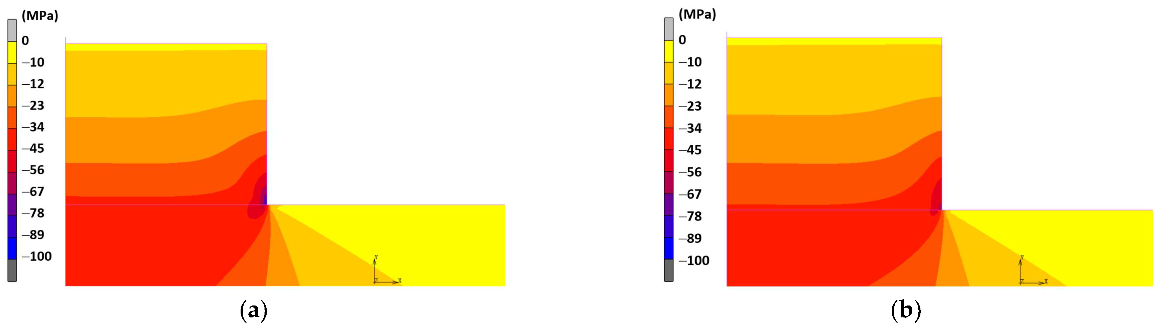
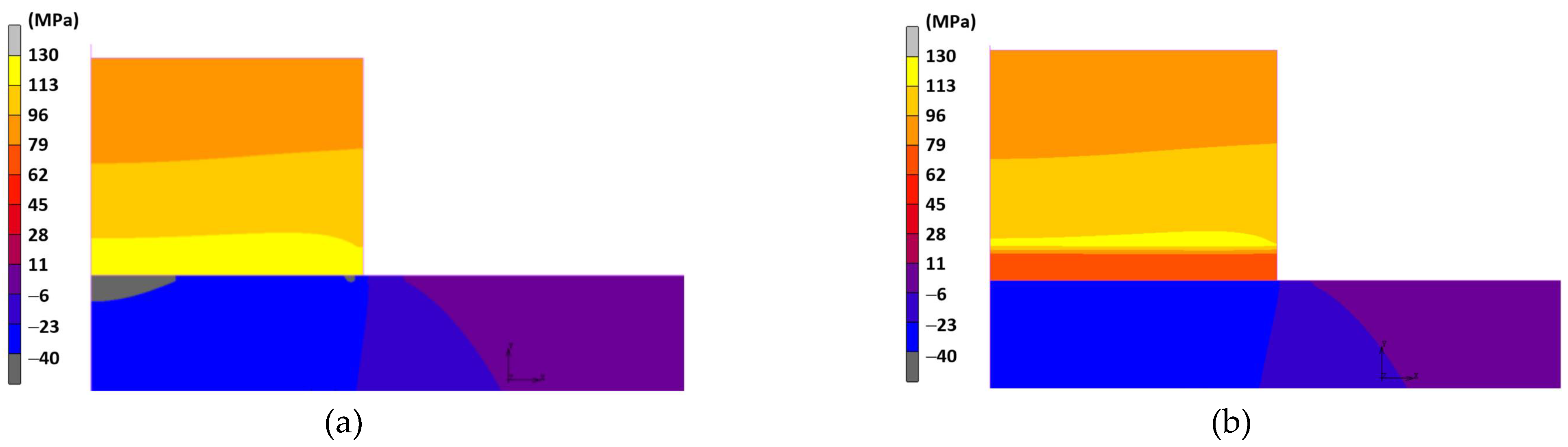
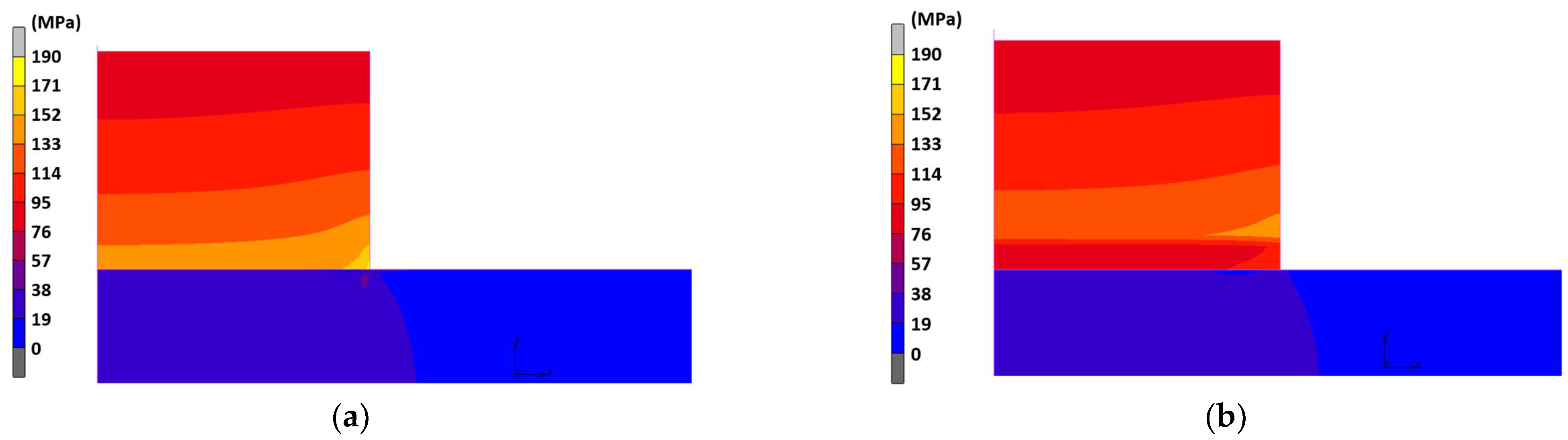
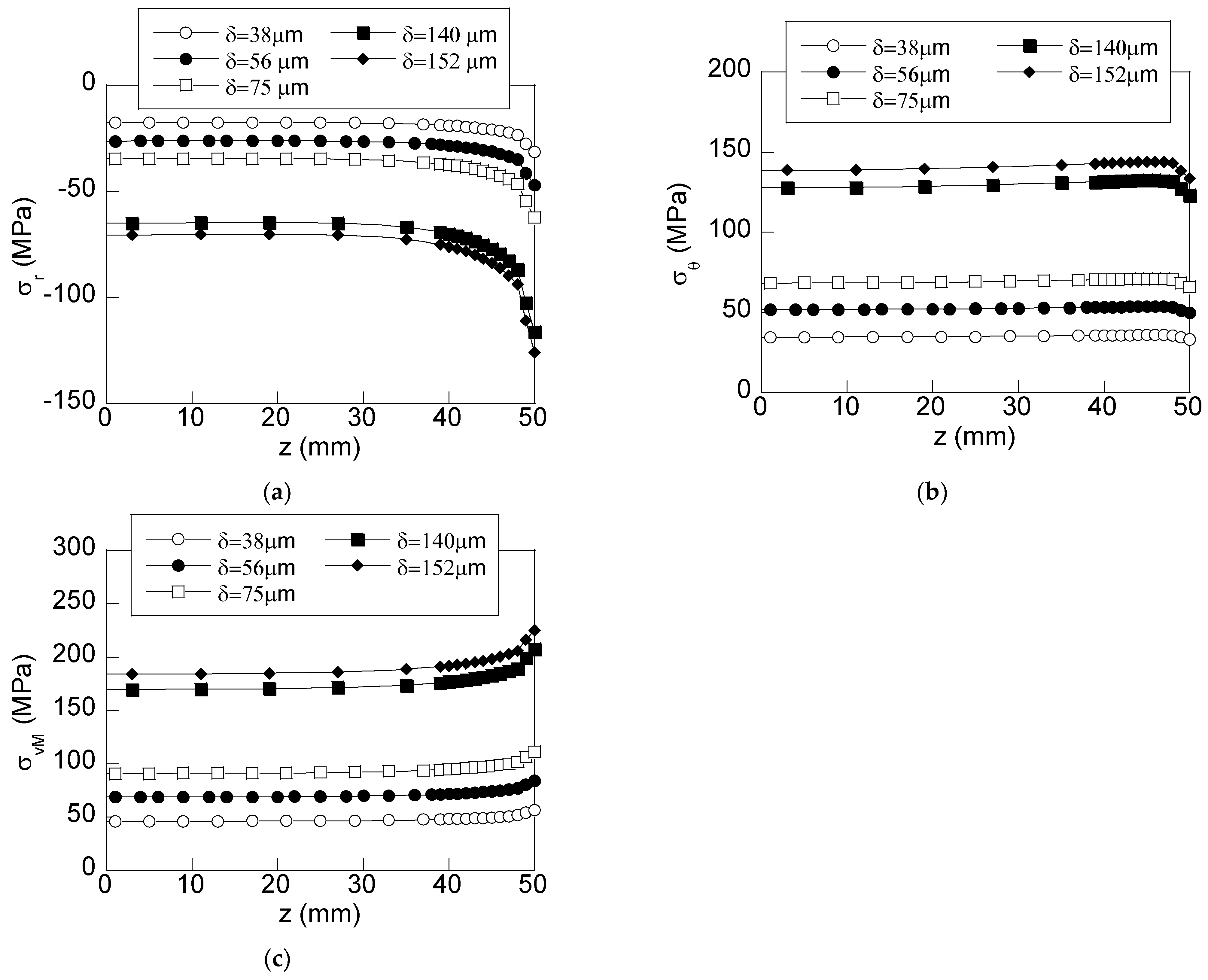
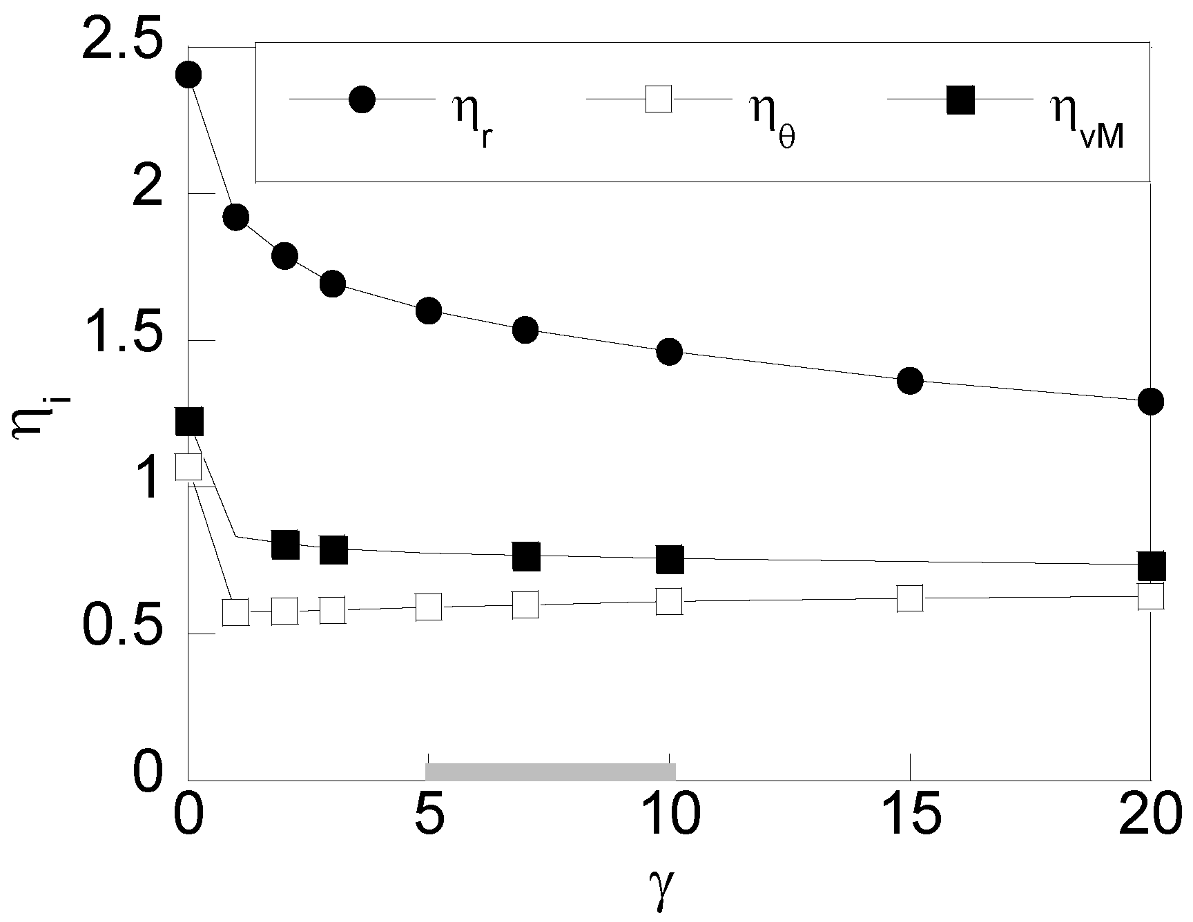
3.1. Influence of the Contact Ring Thickness

To achieve a better understanding of the effect of the contact ring on the stress distribution, the chromatic maps corresponding to the radial, tangential, and von Mises stress distributions are shown in Figure 5, Figure 6 and Figure 7 for a conventional fit (without a contact ring) compared with the ones obtained in a shrink fit with a contact ring of 5% of the total hub thickness, γ = 0.050. These distributions allow one to obtain in a qualitative way the effect of the contact ring on the stress field.
As can be observed, at the interface of the shaft/hub, a high-stress concentration appears (right side of the hub). This concentration is more intense in the radial component at the hub (Figure 5). In a similar way, it is observed that in the tangential stress (Figure 6) and von Mises stress (Figure 7) fields, the maximum values are moved towards the interface of the hub/contact ring. However, the values of the stress undergone in the case of the contact ring are lower than the ones obtained in the case of a fit with a conventional hub (Figure 5, Figure 6 and Figure 7a).
To go deep into the analysis and quantify the effect previously described, in Figure 8, the axial distributions are shown for the radial stress and in a similar way, Figure 9 for the tangential stress and Figure 10 for the von Mises stress for each case of study.
According to the results shown in Figure 8, the radial stress is uniformly distributed throughout the interface up to the vicinity of the hub edge (z > 40 mm). There, a high increment of the radial stress is observed reaching the maximum value at the edge of the hub (z = 50 mm), revealing the well-known huge stress concentration. Regarding the stress distribution in shrink fits using contact rings, the same shape with a stress concentration at the hub edge is obtained, but key changes can be easily observed in those distributions. Firstly, the radial stress at the edge of the hub decreases as the contact ring thickness is increased, reaching a stress reduction of up to half. In addition, it can be observed that the zone of high stress (right side of the plot) is reduced as the contact ring thickness is increased. In a similar way, the radial stress at the central section of the hub (where such stress is uniformly distributed) is reduced with the contact ring thickness, but in a less marked way, being only noticeable for contact ring thicknesses higher than 12.5% of the total thickness. Taking into account the relationship between the maximum transmitted torque and the contact pressure (equal to the radial stress but with the opposite sign), it can be concluded that the contact ring let to reduce, in both magnitude and size, the stress concentration appearing at the edge of the hub without causing significant changes in the maximum transmitted torque (always lower than 10%) since the contact pressure distribution is similar far away to the stress concentrator.
With regard to the axial distribution of the tangential stress shown in Figure 9, such stress is slightly increased from the center section of the hub (z = 0) up to reaching a maximum value nearby the hub edge and afterward is suddenly decreased to reach the minimum value at the hub edge (z = 50 mm). As in the case of the previously discussed for radial stress, the shape of the distributions is similar for the diverse cases of study considering contact rings. However, the following changes are observed: (i) the stress at the hub edge (z = 50 mm) is increased as the contact ring thickness is increased, and (ii) the stress at the inner points (0 < z < 40 mm) is also increased. Thus, it deserves to highlight that the effect of the contact ring on the tangential stress is just the opposite of the effect on the radial stress.
Finally, for the von Mises stress (Figure 10), the stress distribution at the interface is slightly increasing from the hub center section (z = 0 mm) up to z = 45 mm and afterward is suddenly increased, reaching the maximum value at the hub edge (z = 50 mm).
Regarding the effect of the contact ring, it is only noticeable in the high-stress zone nearby the hub edge (z > 40 mm) where the stress is progressively reduced as the contact ring thickness is increased in a similar way as it was observed for the radial stress. For inner points (0 < z < 40 mm) the axial distributions obtained for the diverse contact ring thickness ratios are quite similar and no significant changes are observed.

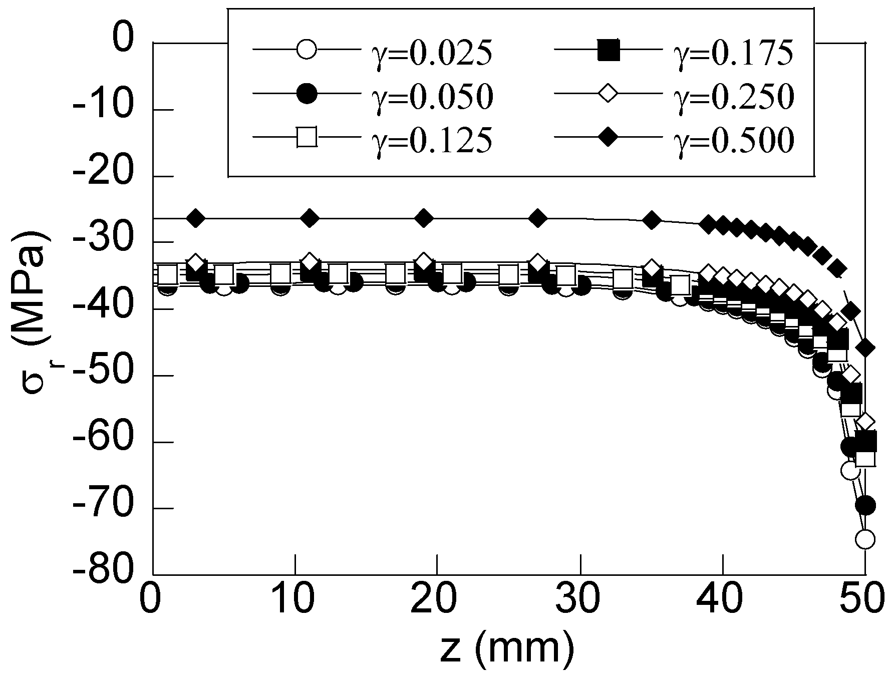
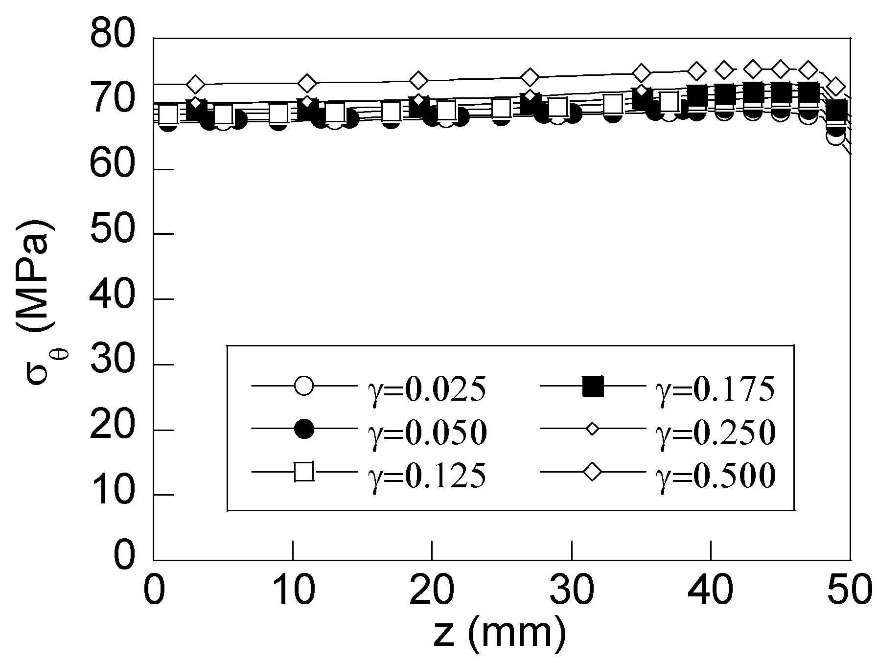
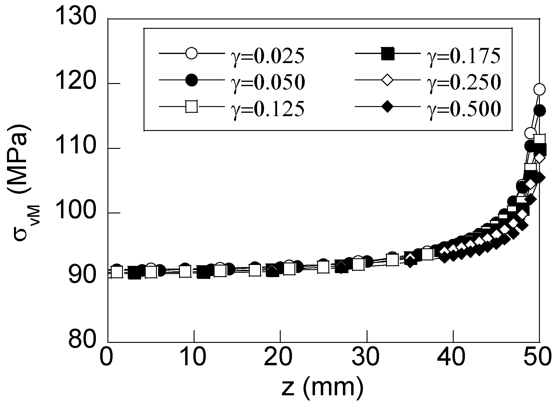
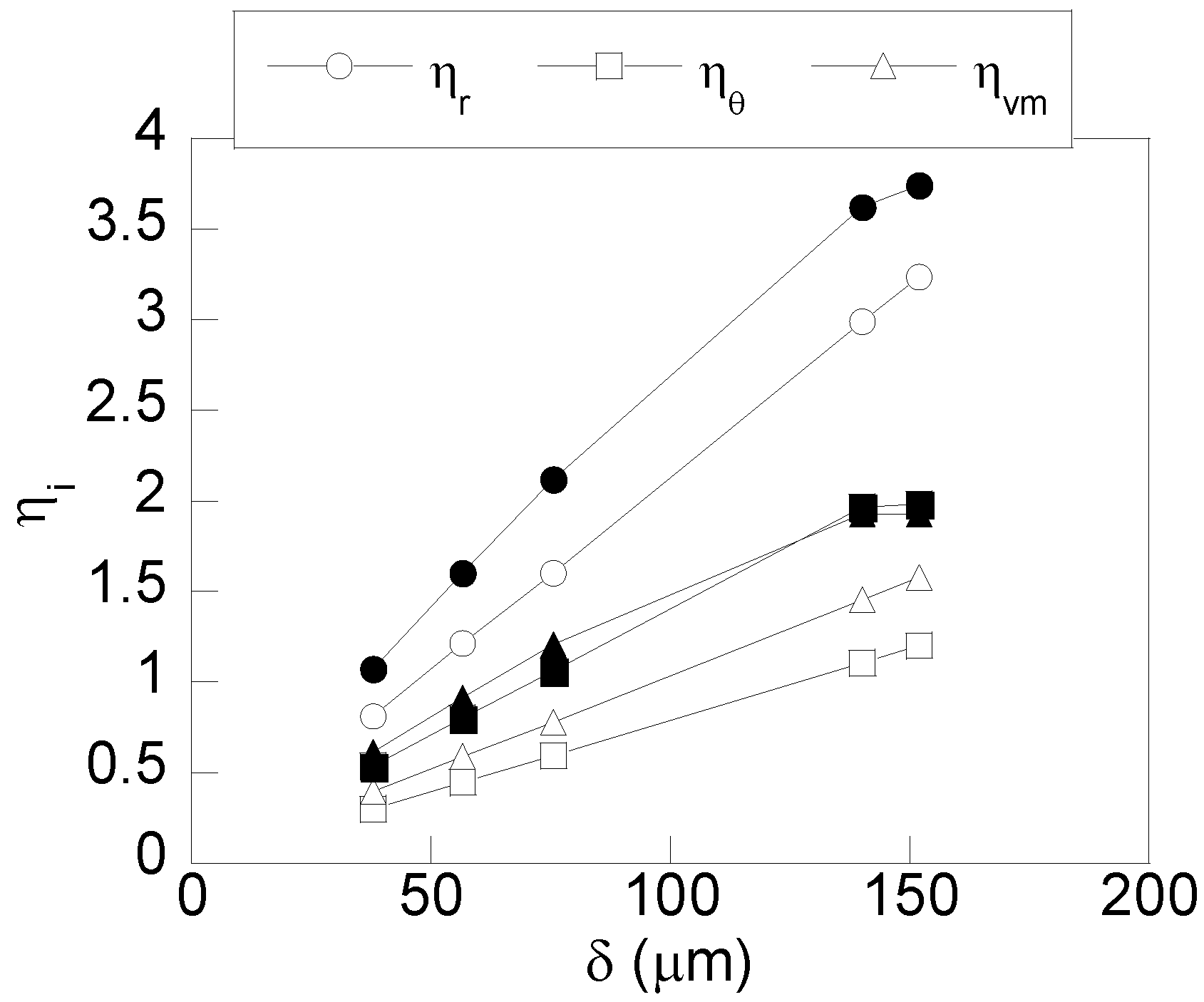
3.2. Influence of the Radial Interference

To quantify the influence of the radial interference (δ) and of the type of interference fit, three different values of the interference closure were selected for the reference interference fit 200H7/s6 (δ = 38 μm, δ = 56 μm, and δ = 75 μm) and, on the other hand, two additional interference fits recommended by the ISO standard for fits and tolerances were chosen causing moderate press (200H7/v6) and severe press (200H7/x6). Previous studies demonstrated that these fits generate different levels of plasticity (local and generalized) in conventional hubs manufactured with a steel AISI 1085 [27]. To reveal the influence, those interferences fit, they were simulated considering two different contact ring thicknesses (γ = 0.125 and γ = 0.250), both included within the recommended range discussed in the previous section. This way, FE simulations reveal the stress state whose axial distributions of radial, tangential, and von Mises stress at the interface are shown in Figure 11 for each case of study.
As can be expected, the stress state is higher as the radial interference (δ) is increased, without causing changes in the shape of the stress distributions. For the case of the moderate press fit (200H7/v6), the stress concentration in a conventional hub (without a contact ring) is so high that it causes a plastic zone at the edge of the hub, as was revealed in previous studies [27]. However, in the case of an interference fit using a contact ring, the reduction in the stress concentration is high enough for making the plastic strains not appear anywhere in the hub, neither at the interface of the shaft/contact ring nor the interference contact of the ring/hub. In the case of the severe fit (200H7/x6), a similar effect can be observed. In this case, generalized plasticity is generated at the interface of the shaft/hub for the conventional hub case [27], whereas, in the case of using a contact ring, again, the reduction in the stress state is high enough to make plastic strains not appear anywhere in the hub since the von Mises stress is always lower than the material yield strength. It must be taken into account that the existence of plastic strains in the interface of the shaft/hub can compromise the effective performance of the fit since this can cause vibrations or modify the contact pressure and hence the maximum transmitted torque.

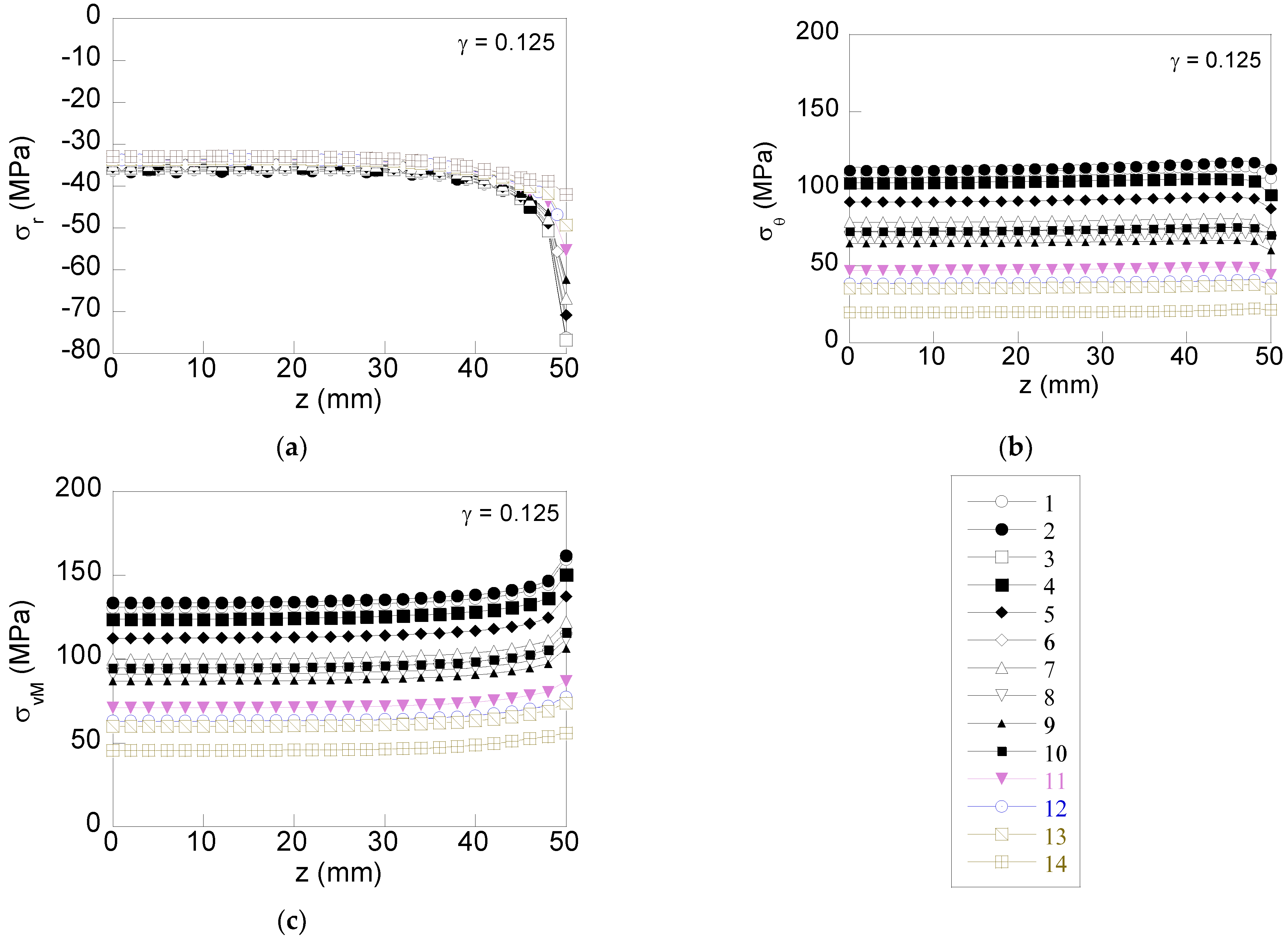
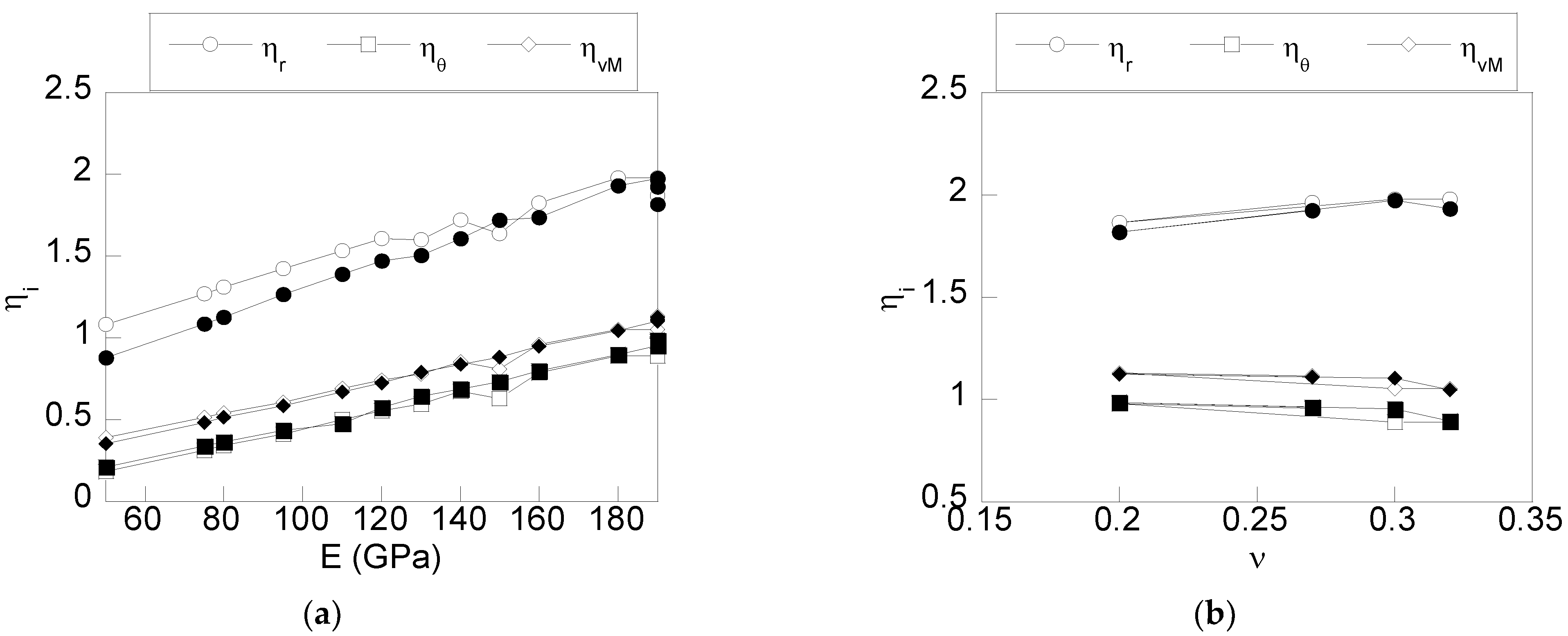
3.3. Influence of the Mechanical Properties of the Material of the Contact Ring

To reveal the influence of the mechanical properties of the contact ring on the stress distribution of an interference fit, diverse shrink fits were modeled and simulated by FEM considering different values of stiffness (varying the material Young modulus) with a similar or higher strength (yield strength) than the material used (steel AISI 1085) in the conventional shrink fit for the shaft and the hub. As was previously discussed, it is well known that this method for reducing the stress at the shaft/hub interface is effective when the material of the contact ring exhibits more flexibility than the one used for the hub, or in other words, the Young modulus of the contact ring must be lower than the one used for the hub. For these reasons, all the materials with a Young modulus higher than AISI 1085 (E = 200 GPa) were excluded. Another requirement was the working temperature since during the manufacturing process, the shrink fit can undergo temperatures higher than 200 °C. Taking into account these requirements, 14 different materials were selected, whose material properties are collected in Table 1. The materials were numbered in such an order decreasing with their Young modulus.
All the cases simulated correspond to the reference shrink fit 200H7/s6. A total of 28 simulations were carried out; 14 of them correspond to a hub with a contact ring thickness ratio of γ = 0.125, manufactured with each one of the 14 materials listed in Table 1, and on the other hand, the remaining 14 simulations correspond to a contact ring thickness ratio of γ = 0.250 in a similar way. The axial distributions of the radial, tangential, and von Mises stresses were obtained at the interface for each case of study (Figure 12).
As was observed in the axial distribution of the radial component (Figure 12a), the stress concentration at the hub edge surroundings (45 mm < z < 50 mm) decreases in a progressive way when materials with a lower Young modulus are used. However, this influence disappears far from the stress concentrator (hub edge) with the stress distribution being very similar for all the materials selected. This supposes that the maximum transmitted torque will undergo slight variations when a contact ring with a lower stiffness were used. In the case of the axial distribution of the tangential stress, the contact ring markedly modifies the magnitude of the stress distribution causing a progressive reduction as the Young modulus is reduced at both the hub edge vicinity and the inner points. As a consequence, the von Mises stress distribution also exhibits similar behavior, decreasing the magnitude throughout the interface as the Young modulus of the contact ring is decreased.

4. Discussion

Differences in the stress state appearing at the interface shaft/hub have been quantified from the dimensionless parameter ηI = σi,modifiedi,theoretical defined as the ratio between the maximum stress of the modified hub considering a contact ring (σi,modified) and the stress given by the theory of pressure cylinders for a conventional interference fit (σi,theoretical), i being the radial, tangential, and von Mises stress components. The variation of these parameters with the contact ring thickness ratio is shown in Figure 13.
According to the results shown in Figure 13, the stress concentration factor obtained using contact rings is lower than the one obtained in a conventional shrink fit (γ = 0). This effect is observed even for low-thickness contact rings. In the case of the parameter radial ηr, the stress concentration is decreased as the contact ring thickness increases. Such a decrease is more marked for low thickness ratios (0 < γ < 0.250) and becomes soft for higher thickness ratios. The variation of the von Mises parameter similarly decreases with the contact ring thickness ratio, whereas the tangential parameter is softly increased with γ. Thus, according to the obtained results for contact rings with thickness ratios within the range 0.125 < γ < 0.250, a reduction in the stress with regard to a conventional fit (without a contact ring) as high as 40% is obtained: radial component (39.1%); tangential (44%); and von Mises (38%). Instead of this, stress reduction increases with the contact ring thickness ratio and, consequently, will be higher for high values of γ; from a practical point of view, it is considered that the contact ring thickness should be notably lower than the total hub thickness. Therefore, according to the obtained results, it is considered that the recommended contact ring thickness must be included within the range 0.125 < γ < 0.250.
From the obtained results, the influence of the contact ring thickness ratio can be derived in terms of the following equations that were obtained by fitting the curves shown in Figure 13 using a quadratic interpolation resulting the following equations for estimating the parameters η radial, tangential, and von Mises, respectively:
η r = 0.00181   γ 2 0.06686   γ + 1.92640 ,         R 2 = 0.9700
η θ = 0.00010   γ 2 + 0.0050 X   γ + 0.57006 ,         R 2 = 0.9983
η v M = 0.00033   γ 2 0.01110   γ + 0.83144 ,         R 2 = 0.9519
According to the results, the correlation coefficient is higher than 0.95, so these equations can be useful for estimating the degree of reduction in terms of the dimensionless contact ring thickness within the interval analyzed.
Regarding the variation of the parameter η with the interference radial, it can be seen that it increases linearly with the radial interference for all the cases considered η (radial, tangential, and von Mises). It must be remarked that for the case of the higher contact ring thickness of γ = 0.250 (blank symbol in Figure 14), the stress concentration is lower.
To complete the analysis and quantify the stress reduction, from the stress distributions of Figure 12, the variation with the Young modulus of the material of the contact ring of the parameter η was obtained for the 28 cases of study (Figure 15a). It deserves to highlight that among the selected materials, four of them had a similar Young modulus (around 190 GPa) and different Poisson coefficients varying within a range of 0.2 and 0.33. This fact allowed us to analyze the influence of the Poisson coefficient on the stress concentration from the results included in Figure 15b.
Results show a linear variation of the η radial, tangential, and von Mises with the Young modulus. In such a way, it can be concluded that the lower the Young modulus of the material of the contact ring, the lower the stress concentration at the edge of the hub. This is valid for radial, tangential, or von Mises stress. Regarding the variation with the contact ring Young modulus for the two values of the thickness ratio γ considered, the same decreasing trend is obtained with minimal variations for the tangential and von Mises components and slight variations for the radial component being higher for low values of the contact ring Young modulus. Finally, according to the results obtained, the variations of the η parameter with the Poisson coefficient (see Figure 15b) for the cases studied are minimal, resulting in an almost plane curve for all the stress components. In addition, the variation with the contact ring thickness ratio γ is minimal, and, therefore, the influence of this parameter can be considered negligible.
Design equations can be derived from the obtained results in terms of the linear interpolation of the curves shown in Figure 15a.
η r E = 0.00598   E + 0.83372 ,         R 2 = 0.9826 ,     γ = 0.125
η r E = 0.00736   E + 0.55252 ,         R 2 = 0.9896 ,         γ = 0.250
η θ E = 0.00542   E 0.09779 ,         R 2 = 0.9920
η v M E = 0.00505   E + 0.13096 ,         R 2 = 0.9925
According to the results, a correlation coefficient higher than 0.98 is obtained, so these equations can be useful for estimating the degree of reduction in terms of the Young modulus of the material used in the contact ring within the interval analyzed.

5. Conclusions

According to the obtained results, the use of contact rings in interference fits allows one to significantly reduce the stress concentration at the hub edge. The contact ring thickness is revealed as a high influencing factor on stress reductions. Although the stress reduction is increased for high contact ring thickness, a redistribution of the radial stress (linked directly with the contact pressure at the interface) appears, causing a reduction in the contact pressure at the interface far from the stress concentrator, leading to a loss of the maximum transmitted torque. This way, the use of contact rings with 0.125 > γ > 0.250 allows one to notably reduce the stress concentration at the edges of the hub (around 40% versus a conventional shrink fit) with a slight decrease in the contact pressure always lower than the 10%. The quadratic dependence of stress reductions on contact ring thickness is expressed in terms of design equations that allow designers to quantify the stress reduction obtained for a given contact ring thickness ratio. In addition, the stress reduction obtained using contact rings with a thickness ratio within the range 0.125 > γ > 0.250 is also useful for moderate and severe interference fits. Thus, high contact pressure can be obtained without generating plastic strains at the interface, improving the performance of the interference fit during its service life. Finally, the results revealed a linear dependence of the stress reduction with the contact ring stiffness. Thus, the lower the Young modulus of the contact ring, the lower stress reduction at the hub edge vicinity without significant changes of the contact pressure, or in other words, without reducing the maximum transmitted torque. This linear dependence is expressed in terms of design equations that allow the designer to quantify the stress reduction for a given contact ring stiffness.

Author Contributions

Conceptualization, M.L.; methodology, M.L., E.I., M.R.-M. and R.G.; software, M.L., E.I., M.R.-M. and R.G.; validation, M.L., E.I., M.R.-M. and R.G.; formal analysis, M.L., E.I., M.R.-M. and R.G.; writing—original draft preparation, M.L., E.I., M.R.-M. and R.G.; writing—review and editing, M.L., E.I., M.R.-M. and R.G.; funding acquisition, M.L. All authors have read and agreed to the published version of the manuscript.

Funding

This research was funded by the Fundación Memoria D. Samuel Solorzano Barruso, grant numbers FS/32-2017 and FS/12-2021.

Institutional Review Board Statement

Not applicable.

Informed Consent Statement

Not applicable.

Data Availability Statement

Not applicable.

Conflicts of Interest

The authors declare no conflict of interest. The funders had no role in the design of the study; in the collection, analyses, or interpretation of data; in the writing of the manuscript; or in the decision to publish the results.

References

  1. Radi, E.; Lanzoni, L.; Strozzi, A.; Bertocchi, E. Shaft-hub press fit subjected to bending couples: Analytical evaluation of the shaft-hub detachment couple. Appl. Math. Model. 2017, 50, 135–160. [Google Scholar] [CrossRef]
  2. Zhang, Y.B.; Lu, L.T.; Zou, L.; Zeng, D.F.; Zhang, J.W. Finite element simulation of the influence of fretting wear on fretting crack initiation in press-fitted shaft under rotating bending. Wear 2018, 400–401, 177–183. [Google Scholar] [CrossRef]
  3. Lorenzo, M.; Pérez-Cerdán, J.C.; Blanco, C. Influence of the thermal assembly process on the stress distributions in shrink fit joints. Key Eng. Mater. 2014, 572, 205–208. [Google Scholar] [CrossRef]
  4. Krol, R.; Siemiatkowski, Z. The analysis of shrink-fit connection the methods of heating and the factor influencing the distribution of residual stresses. Heliyon 2019, 5, e02839. [Google Scholar] [CrossRef]
  5. Apatay, T.; Arslan, E.; Mack, W. Effects of homogeneous and inhomogeneous heating on rotating shrink fits with annular inclusion and functionally graded hub. J. Therm. Stress. 2019, 42, 1458–1479. [Google Scholar] [CrossRef] [Green Version]
  6. Norton, R.L. Machine Design, 5th ed.; Prentice Hall: New York, NY, USA, 2013. [Google Scholar]
  7. Shigley, J.E.; Mischke, C.R. Standard Handbook of Machine Design, 3rd ed.; McGraw-Hill: New York, NY, USA, 2004. [Google Scholar]
  8. Peterson, E.; Wahl, A.M. Fatigue of shafts at fitted members with related photoelastic analysis. J. Appl. Mech. 1935, 57, A1–A11. [Google Scholar] [CrossRef]
  9. Ryazantseva, I.L.; Fedorova, M.A.; Zgonnik, I.P. Contact pressure in interference joint with modified grooves of shallow depth. J. Phys. 2020, 1441, 012111. [Google Scholar] [CrossRef] [Green Version]
  10. Truman, C.E.; Booker, J.D. Analysis of a shrink-fit failure on a gear hub/shaft assembly. Eng. Fail. Anal. 2007, 14, 557–572. [Google Scholar] [CrossRef]
  11. Hao, D.; Wang, D. Finite-element modeling of the failure of interference-fit planet carrier and shaft assembly. Eng. Fail. Anal. 2013, 33, 184–196. [Google Scholar] [CrossRef]
  12. Li, R.; Zhang, C.; Zhan, L.; Cui, Y.; Shen, W. Expanding the applicable duration for shrink fitting of the ultrathin-walled reactor coolant pump rotor-can. Ann. Nucl. Energy 2017, 110, 1217–1223. [Google Scholar] [CrossRef]
  13. Shu, Y.; Yang, G.; Liu, Z. Experimental study on fretting damage in the interference fit area of high-speed train wheels and axles based on specimen. Eng. Fail. Anal. 2022, 141, 106619. [Google Scholar] [CrossRef]
  14. Bengeri, M.; Mack, W. The influence of the temperature dependence of the yield stress on the stress distribution in a thermally assembled elastic-plastic shrink fit. Acta Mech. 1994, 103, 243–257. [Google Scholar] [CrossRef]
  15. Sen, S.; Aksakal, B. Stress analysis of interference fitted shaft-hub system under transient heat transfer conditions. Materials & Design 2004, 25, 407–417. [Google Scholar] [CrossRef]
  16. Reshetov, D.N. Machine Design, 1st ed.; Mir: Moscow, Russia, 1978. [Google Scholar]
  17. Baldanzini, N. A general formulation for designing interference-fit joints with elastic–plastic components. J. Mech. Des. 2004, 126, 737–743. [Google Scholar] [CrossRef]
  18. Arshan, E.; Mack, W. Shrink fit with solid inclusion and functionally graded hub. Compos. Struct. 2015, 121, 217–224. [Google Scholar] [CrossRef]
  19. Lorenzo, M.; Blanco, C.; Moreno, P.; Pérez Cerdán, J.C. Influence of geometry on the stress peaks in interference fits with grooved hub. Dyna 2016, 91, 47–51. [Google Scholar] [CrossRef] [Green Version]
  20. Siva Prasad, N.; Sashikanth, P.; Ramamurti, V. Stress distribution in interference joints. Comput. Struct. 1994, 51, 535–540. [Google Scholar] [CrossRef]
  21. Zhang, Y.; McClain, B.; Fang, X.D. Design of interference fits via finite element method. Int. J. Mech. Sci. 2000, 42, 1835–1850. [Google Scholar] [CrossRef]
  22. Özel, A.; Temiz, Ş.; Demir Aydin, M.; Şen, S. Stress analysis of shrink-fitted joints for various fit forms via finite element method. Mater. Des. 2005, 26, 281–289. [Google Scholar] [CrossRef]
  23. Croccolo, D.; Vincenzi, N. Stress concentration factors in compression-fit couplings. Proc. Inst. Mech. Eng. Part C J. Mech. Eng. Sci. 2010, 224, 1143–1152. [Google Scholar] [CrossRef]
  24. Mohan, A.; Julyes Jaisingh, S.; Babu Aurtherson, P. Fatigue analysis of thermal shrink-fit autofrettage in pressure cylinder using finite element analysis. J. Mater. Res. Technol. 2020, 9, 8606–8617. [Google Scholar] [CrossRef]
  25. Cui, Y.; Zhang, L.; Zhang, C.; Li, R.; Li, F. Stress analysis of shrink fitting process of ultra-thin reactor coolant pump rotor-can. Ann. Nucl. Energy 2021, 162, 108492. [Google Scholar] [CrossRef]
  26. ISO 286-1:2010; Geometrical Product Specifications (GPS)—ISO Code System for Tolerances on Linear Sizes—Part 1: Basis of Tolerances, De-viations and Fits. International Organization for Standardization: Geneve, Switzerland, 2010; p. 38.
  27. Pérez Cerdán, J.C.; Lorenzo, M.; Blanco, C. Effects of plasticity induced by assembly process on contact pressure of shrink fits with grooved hubs. Mech. Mach. Sci. 2014, 17, 393–400. [Google Scholar] [CrossRef]
Figure 1. Scheme of a shrink fit using a contact ring.
Applsci 12 10037 g001
Figure 2. Scheme of the simplified geometry and boundary conditions applied in FEM simulations.
Applsci 12 10037 g002
Figure 3. Mesh used in FEM simulations: (a) general view, (b) detail view at the hub edge where stress concentration appears.
Applsci 12 10037 g003
Figure 4. Mesh convergence validation for contact pressure p and relative error ε in terms of mesh factor K, defined as the ratio between the number of elements of each mesh and the number of elements of the coarsest mesh, corresponding to: (a) a case considering the hub and shaft composed of the same material and (b) a case considering the hub and shaft composed of different materials.
Applsci 12 10037 g004
Figure 5. Distributions of the radial stress in: (a) a conventional shrink fit (without a contact ring) and (b), a modified shrink fit with a contact ring (γ = 0.050).
Applsci 12 10037 g005
Figure 6. Distributions of the tangential stress in: (a) a conventional shrink fit (without a contact ring), and (b) a modified shrink fit with a contact ring (γ = 0.050).
Applsci 12 10037 g006
Figure 7. Distributions of the von Mises stress in: (a) a conventional shrink fit (without a contact ring), and (b) a modified shrink fit with a contact ring (γ = 0.050).
Applsci 12 10037 g007
Figure 8. Axial distributions of the radial stress at the interface contact ring/shaft for diverse values of the thickness ratio.
Applsci 12 10037 g008
Figure 9. Axial distributions of the tangential stress at the interface contact of the ring/shaft for diverse values of the thickness ratio.
Applsci 12 10037 g009
Figure 10. Radial distributions of the von Mises stress at the interface contact of the ring/shaft for diverse values of the thickness ratio.
Applsci 12 10037 g010
Figure 11. Axial distributions at the interface of: (a) radial stress, (b) tangential stress, and (c) von Mises stress for diverse levels of radial interference (γ = 0.125).
Applsci 12 10037 g011
Figure 12. Axial distributions at the interface shaft-hub of: (a) radial stress, (b) tangential stress, and (c) von Mises stress for diverse materials of the contact ring (γ = 0.125).
Applsci 12 10037 g012
Figure 13. Variation of the parameter η radial, tangential, and von Mises as a function of the contact ring thickness ratio.
Applsci 12 10037 g013
Figure 14. Variation of the parameter η radial, tangential, and von Mises as a function of the radial interference (blank symbols, γ = 0.125 and full symbols, γ = 0.250).
Applsci 12 10037 g014
Figure 15. Variation of the parameter η radial, tangential, and von Mises (a) as a function of the material Young modulus of the contact ring, and (b) against the Poisson coefficient of the material of the contact ring (blank symbols, γ = 0.125 and full symbols, γ = 0.250).
Applsci 12 10037 g015
Table 1. Mechanical properties of the materials selected for the contact ring.
Id.MaterialCommercial CodeEo (GPa)νοσY (GPa)
1Stainless steel316L1900.27310
2Cr–Ni50Cr-50Ni1900.20340
3NI–Be4401900.301030
4Ni–Cu (Monel)Monel 4001800.32630
5NI–FeK950S1600.29290
6Cu–NiCuNi2Si1500.34450
7Ni low alloyN032601400.31295
8Cu–BeTH041240.28965
9Cu–AlCuAl101200.34320
10Cu–MnC675001100.34310
11TiTi24Al11Nb950.36581
12ZnZ35841800.32345
13Al–CuA9 2618750.33266
14Mg–AlElectronZC71550.30310
Publisher’s Note: MDPI stays neutral with regard to jurisdictional claims in published maps and institutional affiliations.

