
Anti-Islanding Method Development Based on Reactive Power Variation under Grid Support Environments

Division of Electrical, Electronic and Control Engineering, Regional-Industrial Application Research Institute and Institute of IT Convergence Technology, Kongju National University, Cheonan-si 31080, Korea
Appl. Sci. 2022, 12(18), 9074; https://doi.org/10.3390/app12189074
Submission received: 18 August 2022
/
Revised: 5 September 2022
/
Accepted: 6 September 2022
/
Published: 9 September 2022
(This article belongs to the Special Issue Advances of Energy Efficiency in Electrical Engineering and Electronics)
Abstract
:Featured Application
Grid Connected Inverter.
Abstract
As the proportion of distributed generation (DG), including Photovoltaic (PV) generation, in the power grid system increases, there are dropouts of large-scale distributed power generation sources due to some transient conditions that negatively affect the power grid stability and power quality. Accordingly, the inverter for DG generation is in a transition period, requiring more complex control performance. Anti-islanding function requirements in particular are becoming more strict because sophisticated grid-connection requirements are demanded, such as voltage ride-through, frequency ride-through, rate of change of frequency, and other functions. Thus, highly advanced anti-islanding methods are required to detect the islanding condition quickly and accurately to stop the inverter. This paper presents the improved anti-islanding method based on reactive power variation (RPV) under grid-support environments for single-phase DG inverters. In order to verify the validity of the proposed method, PSIM simulation was conducted. The proposed method meets the requirements of IEEE Std. 1547-2018 and KS C 8564:2021 by preventing islanding within 0.007 s under the newly adopted voltage/frequency trip setting, while the conventional RPV method fails.
1. Introduction
The islanding operation of distributed generation (DG) refers to a phenomenon in which electricity is continuously generated from the DG despite a power outage in the power grid [1]. This islanding operation causes many problems, such as a potential electric shock at the Point of Common Coupling (PCC) that was considered to be inactive, a high inrush current due to reconnection after power recovery, damage to the circuit breaker, an increase in harmonics, and flickering [2,3,4,5]. Therefore, many domestic and foreign standards require the function of the anti-islanding method (AIM) to stop the generation of DGs when the grid is disconnected, with the goal of securing safety [6,7]. As a part of the energy transition, renewable-energy-based DGs, such as Photovoltaic (PV) and wind power, are occupying more and more parts of the power grid worldwide [8,9,10]. For this reason, there is a dropout of large-scale DG sources due to a partial transient state of the power grid, which adversely affects the stability and power quality of the power grid, involving issues such as false tripping of feeders, blinding of protection, and unintentional islanding occurring [11,12,13,14].
In order to respond to this issue, recent power regulations require a function to maintain the connection to the power grid as much as possible, control active power or reactive power, or both in response to variations in voltage and frequency in the power system [15,16,17]. This is called the grid support function of DG resources, and the enactment is being promoted as a grid regulation of each country around the world [18,19,20,21]. However, the grid support function creates a very difficult condition for detecting the islanding phenomenon with the conventional technology. Accordingly, many studies are being conducted to create a new islanding detection technique in response to these challenging problems [22,23,24].
The conventional AIM is divided into a passive method and an active method [1]. The passive method simply monitors the main parameters, such as voltage/frequency/phase of the inverter’s output stage, and when it exceeds the set value, it is determined as islanding operation [25,26,27]. In the passive method, when the generated power and the load power of the DG are balanced, the fluctuation amount of the main parameter is not large, and there is a problem that the islanding cannot be detected. On the other hand, the active method forcibly changes parameters, such as current/frequency/phase/active power/reactive power, and causes a large change in the parameter after islanding operation occurs, so that it is designed to exceed the set value [28,29,30]. As shown in Figure 1, active methods based on the frequency variation include active frequency drift (AFD), active frequency drift with positive feedback (AFDPF), slip mode frequency shift (SMS), and reactive power variation (RPV) methods. The AFD method in particular uses the chopping fraction, cf, as a frequency perturbation parameter, which is defined as the ratio of zero time (tz) to half of the period of voltage waveform (T1/2). Its concept is based on varying the frequency of the inverter output current. If the frequency of the inverter voltage is out of the frequency relay set value after islanding occurs, it is determined to be an islanding operation, and the inverter stops. This technique inherently raises the harmonic component of the current, thereby lowering the power quality. It also has a limitation in that the performance varies depending on the value of the resonance index of the RLC local load. Another representative active method is a technique of periodically changing reactive power causing frequency fluctuations due to fluctuations in reactive power when islanding occurs. This method inherently lowers the value of the displacement power factor, which has a problem of lowering the power quality, and also has a limitation in that the performance varies according to the value of the resonance index of the RLC local load.
In response to the regulation of the wider voltage/frequency relay setting value change for grid support function, this paper presents the improved anti-islanding method based on reactive power variation (RPV) for single-phase DG inverters. Compared with the conventional RPV method, the proposed method has the advantages of the ability to detect islanding under the recent wider voltage/frequency relay threshold conditions with the same perturbed reactive power variations.
This paper is organized as follows: The recent regulation review on wider voltage/frequency relay threshold is presented in Section 2. Section 3 presents the proposed method with the operational principle. Then, simulation verification is provided in Section 4. Finally, Section 5 concludes this paper.
2. Standard Synopsis
IEEE Std. 1547-2018 and KS C 8564:2021 are representative technical standards that include the latest grid support functions domestically and internationally. This section compares and analyzes the change in voltage/frequency regulation related to the prevention of islanding operation in these two technical standards and the non-detection zone for islanding operation. The major difference between the islanding detection requirements in IEEE Std. 1547-2018 and KS C 8564:2021 is that the required islanding prevention times are 2 s and 0.5 s, respectively. This difference comes from the technical specifications, such as the reclosing time to fault current of each country’s power grid. In both standards, the grid code for abnormal voltage magnitude and frequency threshold value has changed as the proportion of DG increases in the power grid.
Table 1 and Table 2 show the clearing time of DG according to the abnormal voltage and frequency, respectively. Clearing time is defined as the time between the start of an abnormal condition and the DG ceasing to energize the connected grid. Table 1 shows the required clearing times for Over Voltage (OV), a voltage larger than the nominal voltage level, and Under Voltage (UV), a voltage smaller than the nominal voltage level. In the case of IEEE Std. 1547-2018, compared to the previous version, there was no change in the setting value of OV trip; only the clearing time was partially changed, and the setting value of UV trip was lowered, so the allowable range of grid connected operation was wider. In the case of KS C 8564, the UV trip setting value was found to be wider in the same trend. Table 2 shows the required clearing times for Over Frequency (OF), frequencies greater than the nominal frequency level, and Under Frequency (UF), lower than the nominal frequency level. In the case of IEEE Std. 1547-2018, the OF trip set value was 1.5 Hz wider, and the UF trip set value was wider by 2.8 Hz, compared to IEEE Std. 1547-2003, and the allowable range of grid-connected operation was wider. In the same trend, in the case of KS C 8564-2021, the OF trip set value was 1 Hz wider and the UF trip set value was 2.3 Hz wider compared to KS C 8564-2015, so the allowable range of grid-connected operation was wider. This is because a wider voltage/frequency setting was required to prevent the nuisance tripping of DGs, which occurs due to transient operations, such as the switching of capacitor banks and starting of motors. According to this trend, it becomes more difficult to prevent islanding operations with most inverter-based anti-islanding technologies, based on OV/UV/OF/UF relays.
Equations (1) and (2) are quantitative analyses of the non-detection zones of islanding operations according to the voltage/frequency relay threshold values and are summarized in Table 3. By adopting the threshold values like Vmax, Vmin, fmax, and fmin in Table 2 into Equations (1) and (2), quantitative non-detection zones are generated, as shown in Table 3. Since the amount of change in effective power for islanding operation detection must be varied up to 393.8% compared to the rated power, the detection technique by effective power fluctuation is not widely used as a type of active method.
Active techniques based on reactive power fluctuation techniques are widely used. In IEEE Std. 1547, they increase from a maximum of 2.4% to 12.8%, and in KS C 8564, they increase from a maximum of 2.4% to 10.8% to enable the detection of islanding operations based on OF/UF. As can be seen from this point, it can be confirmed that the fluctuation range of reactive power for islanding operation detection based on frequency relay is about 5 times larger.
With this amount of fluctuation, the size fluctuation of reactive power may cause the deterioration of power quality. Therefore, in this paper, based on a small level of reactive power fluctuation, the authors propose an improved technique that can detect islanding operation without reaching the threshold value of the frequency relay.
3. The Proposed Method
As analyzed in the previous section, the amount of change in reactive power for detecting islanding operation by the standards should be increased by up to 13% of the rated power of the solar unit inverter. In this paper, the anti-islanding method with small reactive power variations (RPVs) in a grid-supported environment is presented by proposing an islanding detection indicator without depending on OF/UF thresholds. The magnitude of the injected reactive power is proposed as a change in the phase angle defined in the basic concept of power factor in Equation (3). As shown in Equation (4), the phase angle deviation is designed to use the positive feedback according to the frequency deviation for two consecutive periods. While the grid is connected to DG, the frequency fluctuation for two consecutive cycles is not large and has a very small value due to the frequency sensing error. Therefore, only a very small change in reactive power occurs before islanding occurs. However, when islanding occurs, a small amount of reactive power change causes a corresponding frequency change, which needs to be designed to exceed the threshold value of the frequency relays. As introduced in the previous section, since the latest technical standards require a wider set value of the frequency relay, the size of the reactive power that needs to be changed to detect islanding operation is relatively large, which is a problem. Therefore, in this paper, an islanding detection indicator that can detect islanding operation for even minute-long fluctuations in reactive power is presented as the correlation parameters in Equation (5).
where QRPV is the injected reactive power, Pinv is the inverter output effective power, kp is the positive feedback gain, freq[k] is the measured frequency at the time instant k, Cp is the correlation parameter, and kc is the scaling factor.
Before islanding occurs, the frequency of the inverter voltage is maintained robustly by the power grid, so the frequency is determined regardless of the reactive power fluctuations by the proposed method. Thus, the proposed correlation parameter has a value close to 0, even considering the sensing error when the inverter is connected to the grid. On the other hand, after islanding occurs, the frequency changes in the same direction by the variation of the proposed reactive power, which increases the value of the proposed correlation parameter. When the calculated correlation parameter reaches the designed threshold, it is determined as an islanding operation, and the inverter stops. The author has previously proposed an islanding detection technique using a correlation index based on an AFD method rather than reactive power variations. The previously proposed islanding operation detection method using correlation based on the AFD method has a problem of inherently generating harmonic components while the grid frequency changes [22]. However, the proposed method in this paper has an advantage in power quality as it has a structure in which the harmonic component does not change, but the size of the reactive power component changes. In this paper, the main design parameters are the threshold value of Cp to determine islanding and the magnitude of RPV. The magnitude of the reactive power variation is with positive feedback, and the threshold value of the correlation parameter is designed through a trial-and-error by simulation.
4. Discussion
To verify the feasibility of the proposed method, a 3 kW class grid-connected DG inverter system was implemented using PSIM software, as shown in Figure 2. The main circuit design parameters are shown in Table 4.
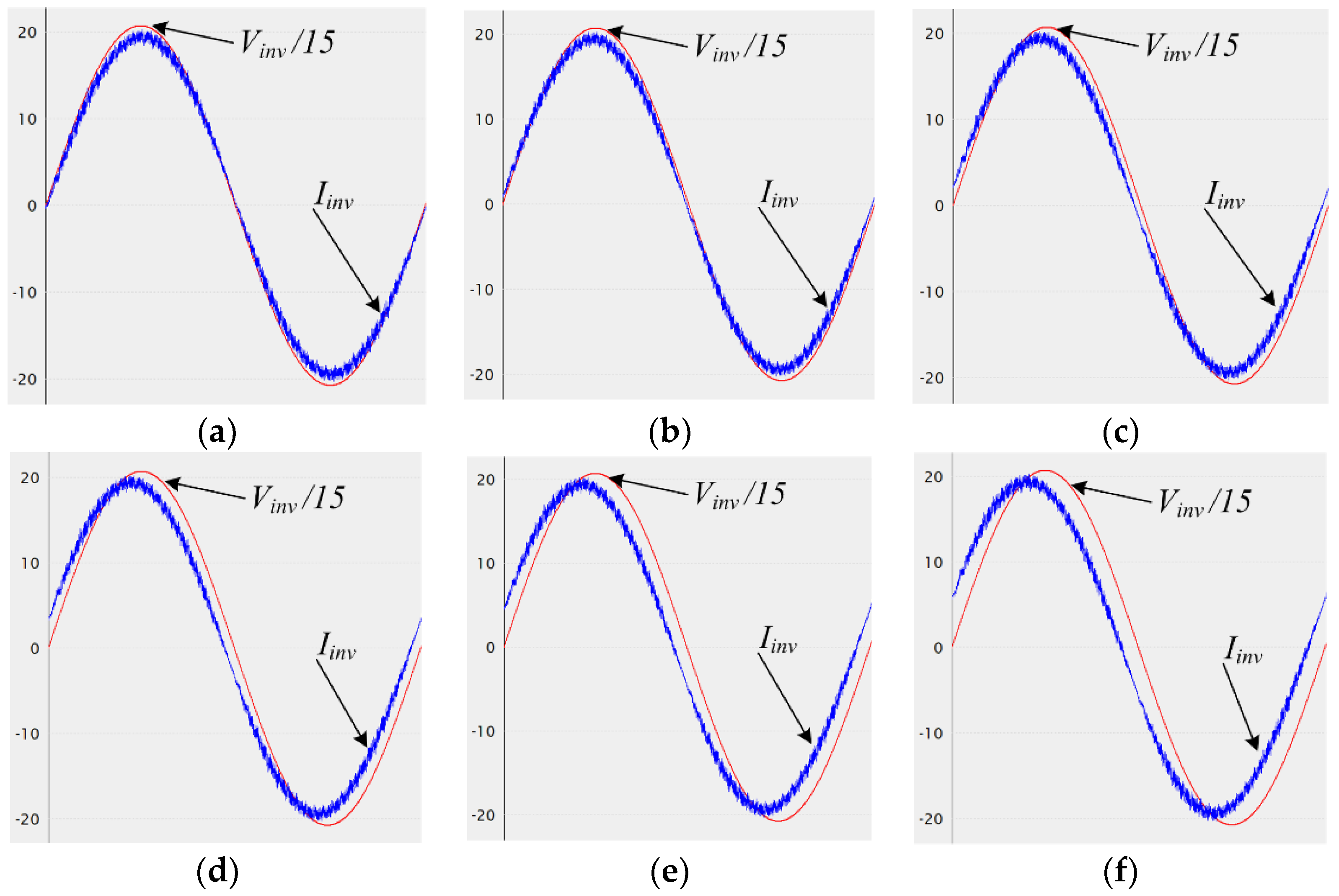
First, the power quality on harmonics was compared and analyzed for the proposed method and the conventional AFD method. Figure 3 shows how the waveform changes as cf, which is the control target of the AFD technique when the grid is connected, and Table 5 shows its Total Harmonic Distortion (THDi) of the current. When the cf value is 0% and there is no disturbance at all, the base THDi is 3.18%, and when the cf value is 5%, the THDi is 5.54%. As cf increases, THDi increases, as the distortion in the fundamental sinusoidal wave increases. Figure 4 shows how the waveform changes as the phase, which is the control target of the proposed method, and Table 5 shows its THDi for the proposed method. It can be seen that the base THDi is 3.18% when the phase disturbance, which is the change in reactive power, is 0%, and the THDi is 3.23% when the phase disturbance is 5%. In other words, it can be seen that even when the phase disturbance increases, there is little change in the THDi because there is no distortion of the fundamental sinusoidal wave component.
As suggested in IEEE Std. 1547-2018 and KS C 8564-2021, the anti-islanding performance evaluation is conducted under the worst test condition, in which the power flows to the grid (∆P, ∆Q) are almost zero since the balance between the DG generation power and the load is made.
Figure 5 shows the inverter output voltage (Vinv), current (Iinv), frequency (Freq), Correlation parameter (Cp), and phase variation (θRPV) for the grid-connected DG inverter when islanding occurs at 0.4 s. In Mode A1 before islanding occurs, the difference in measured frequency between two consecutive periods is very small, up to 0.007, and the phase angle for the proposed reactive power variation is also very small, close to about 0.004, as shown by Equation (4). Therefore, at this time, it can be confirmed that the THDi in Mode A1 is also maintained at the level of 3.18%, as discussed in the previous section. In addition, in Mode A1, the correlation between the frequency difference and the reactive power variation is very low, and the Cp value stays at the maximum level of 0.08. In Mode A2, after islanding occurs, the frequency fluctuations by the proposed method and the corresponding fluctuations in Cp values are shown. By the reactive power variation technique with positive feedback gain Kp of 0.0056, it can be confirmed that the inverter frequency in the steady state stays around 60.55 Hz. Additionally, it can be seen that Cp in Mode A2 has a maximum value of about 7.45. For these frequency fluctuations, it can be confirmed that islanding cannot be detected under the condition of the frequency relay set value in IEEE Std. 1547-2018 and KS C 8564:2021.
Figure 6 shows the waveform that prevents islanding operations by using the proposed technique at about 0.007 s after islanding occurs. Similar to Mode A1, Mode B1 in Figure 6 is the section before islanding operation occurs, and islanding occurs at 0.4 s. When the value of Cp reaches the threshold value of 6 in Mode B2, islanding operation is determined, and in Mode B3, the DG inverter stops. As stated, in IEEE Std. 1547-2018, islanding should be prevented within 2 s under prescribed load conditions, and in KS C 8564, islanding should be prevented within 0.5 s. As described above, the proposed method minimizes the occurrence of harmonics to THD 3.18% in the grid-connected condition and detects the islanding operation in 0.007 s in the worst condition to meet the required technical standards for IEEE Std. 1547-2018 and KS C 8564:2021.
5. Conclusions
This paper presents the improved anti-islanding method based on reactive power variation (RPV) under grid-support environments for single-phase DG inverters. The proposed method meets the requirements of IEEE Std. 1547-2018 and KS C 8564:2021 by preventing islanding within 0.007 s under the newly adopted voltage/frequency trip setting, while the conventional RPV method fails. Since the wider frequency trip range was adopted for grid support environments, the amount of the conventional reactive power variation should be higher. Based on the proposed method, the amount of reactive power for anti-islanding could be minimized by using the proposed correlation parameter. In order to verify the validity of the proposed method, PSIM simulation was conducted. The proposed method could be applied to the reactive power compensation together with an anti-islanding function based on the appropriate reactive power supply profile.
Funding
This work was supported by the National Research Foundation of Korea (NRF) grant funded by the Korea government (MSIT) (No. 2021R1F1A1050199).
Conflicts of Interest
The author declares no conflict of interest.
References
- Hussain, A.; Kim, C.; Mehdi, A. A Comprehensive Review of Intelligent Islanding Schemes and Feature Selection Techniques for Distributed Generation System. IEEE Access 2021, 9, 146603–146624. [Google Scholar] [CrossRef]
- Makwana, Y.; Bhalja, B. Experimental Performance of an Islanding Detection Scheme Based on Modal Components. IEEE Trans. Smart Grid 2019, 10, 1025–1035. [Google Scholar] [CrossRef]
- Pouryekta, A.; Ramachandaramurthy, V.; Mithulananthan, N.; Arulampalam, A. Islanding Detection and Enhancement of Microgrid Performance. IEEE Syst. J. 2018, 12, 3131–3141. [Google Scholar] [CrossRef]
- Murugesan, S.; Murali, V. Disturbance Injection Based Decentralized Identification of Accidental Islanding. IEEE Trans. Ind. Electron. 2020, 67, 3767–3775. [Google Scholar] [CrossRef]
- Ma, J.; Zheng, H.; Zhao, J.; Chen, X.; Zhai, J.; Zhang, C. An Islanding Detection and Prevention Method Based on Path Query of Distribution Network Topology Graph. IEEE Trans. Sustain. Energy 2022, 13, 81–90. [Google Scholar] [CrossRef]
- IEEE Std. 1547-2018; IEEE Standard for Interconnection and Interoperability of Distributed Energy Resources with Associated Electric Power Systems Interfaces. IEEE Standard Association: Piscataway, NJ, USA, 2018.
- KS C 8546:2021; Small Scale Photovoltaic Inverter Testing. Korea Industrial Standards Commission: Daejeon, Korea, 2021.
- Rostami, A.; Jalilian, A.; Zabihi, S.; Olamaei, J.; Pouresmaeil, E. Islanding Detection of Distributed Generation Based on Parallel Inductive Impedance Switching. IEEE Syst. J. 2020, 14, 813–823. [Google Scholar] [CrossRef]
- Chen, G.; Lewis, F.; Feng, E.; Song, Y. Distributed Optimal Active Power Control of Multiple Generation Systems. IEEE Trans. Ind. Electron. 2015, 62, 7079–7090. [Google Scholar] [CrossRef]
- Cady, S.; Dominguez-Garcia, A.; Hadjicostis, C. A Distributed Generation Control Architecture for Islanded AC Microgrids. IEEE Trans. Control Syst. Technol. 2015, 23, 1717–1735. [Google Scholar] [CrossRef]
- Azzaoui, M. An Effective Islanding Detection Method With Wavelet-Based Nuisance Tripping Suppressing. IEEE Trans. Power Electron. 2021, 12, 13792–13801. [Google Scholar]
- Wang, Z.; Xiong, J.; Wang, X. Investigation of Frequency Oscillation Caused False Trips for Biomass Distributed Generation. IEEE Trans. Smart Grid 2019, 10, 6092–6101. [Google Scholar] [CrossRef]
- Faqhruldin, O.; El-Saadany, E.; Zeineldin, H. A Universal Islanding Detection Technique for Distributed Generation Using Pattern Recognition. IEEE Trans. Smart Grid 2014, 5, 1985–1992. [Google Scholar] [CrossRef]
- Kresshan, M.; Fotis, G.; Vita, V.; Ekonomou, L. Distributed Generation Islanding Effect on Distribution Networks and End User Loads Using the Load Sharing Islanding Method. Energies 2016, 9, 956. [Google Scholar] [CrossRef]
- Mukherjee, S.; Chowdhury, R.; Shamsi, P.; Ferdowsi, M. Power-Angle Synchronization for Grid-Connected Converter with Fault Ride-Through Capability for Low-Voltage Grids. IEEE Trans. Energy Convers. 2018, 33, 970–979. [Google Scholar]
- Taul, M.; Wang, X.; Davari, P.; Blaabjerg, F. Robust Fault Ride Through of Converter-Based Generation during Severe Faults With Phase Jumps. IEEE Trans. Ind. Appl. 2020, 56, 570–583. [Google Scholar] [CrossRef]
- Sahoo, A.; Ravishankar, J.; Ciobotaru, M.; Blaabjerg, F. Enhanced Fault Ride-Through of Power Converters Using Hybrid Grid Synchronization. IEEE J. Emerg. Sel. Top. Power Electron. 2022, 10, 2829–2841. [Google Scholar] [CrossRef]
- Johnson, J.; Ablinger, R.; Bruendlinger, R.; Fox, B.; Flicker, J. Interconnection Standard Grid-Support Function Evaluations Using an Automated Hardware-in-the-Loop Testbed. IEEE J. Photovolt. 2018, 8, 565–571. [Google Scholar] [CrossRef]
- Ndirangu, K.; Taft, H.; Fletcher, J.; Konstantinou, G. Impact of Grid Voltage and Grid-Supporting Functions on Efficiency of Single-Phase Photovoltaic Inverters. IEEE J. Photovolt. 2022, 12, 421–428. [Google Scholar] [CrossRef]
- Dong, D.; Agamy, M.; Harfman-Todorovic, M.; Liu, X.; Garces, L.; Zhou, R.; Cioffi, P. A PV Residential Microinverter with Grid-Support Function: Design, Implementation, and Field Testing. IEEE Trans. Ind. Appl. 2018, 54, 469–481. [Google Scholar] [CrossRef]
- Bassey, O.; Butler-Purry, K. Black Start Restoration of Islanded Droop-Controlled Microgrids. Energies 2020, 13, 5996. [Google Scholar] [CrossRef]
- Talha, M.; Raihan, S.; Rhim, N. A Grid-tied PV Inverter with Sag-severity-independent Low-voltage Ride through, Reactive Power Support, and Islanding Protection. J. Mod. Power Syst. Clean Energy 2021, 9, 1300–1311. [Google Scholar] [CrossRef]
- Zamani, R.; Moghaddam, M.; Panai, H.; Sanaye-Pasand, M. Fast Islanding Detection of Nested Grids Including Multiple Resources Based on Phase Criteria. IEEE Trans. Smart Grid 2021, 12, 4962–4970. [Google Scholar] [CrossRef]
- Yu, B. Study on a Correlation-Based Anti-Islanding Method under Wider Frequency Trip Settings for Distributed Generation. Appl. Sci. 2020, 10, 3626. [Google Scholar] [CrossRef]
- Raza, S.; Mokhlis, H.; Arof, H.; Laghari, A.; Mohamad, H. A sensitivity analysis of di_erent power system parameters on islanding detection. IEEE Trans. Sustain. Energy 2016, 7, 461–470. [Google Scholar] [CrossRef]
- Liu, S.; Zhuang, S.; Xu, Q.; Xiao, J. Improved voltage shift islanding detection method for multi-inverter grid-connected photovoltaic systems. IET Gener. Transm. Distrib. 2016, 10, 3163–3169. [Google Scholar] [CrossRef]
- Guha, B.; Haddad, R.J.; Kalaani, Y. Voltage ripple-based passive islanding detection technique for grid-connected photovoltaic inverters. IEEE Power Energy Technol. Syst. J. 2016, 3, 143–154. [Google Scholar] [CrossRef]
- Pourbabak, H.; Kazemi, A. Islanding detection method based on a new approach to voltage phase angle of constant power inverters. IET Gener. Transm. Dis. 2016, 10, 1190–1198. [Google Scholar] [CrossRef]
- Wen, B.; Boroyevich, D.; Burgos, R.; Shen, Z.; Mattavelli, P. Impedance-Based Analysis of Active Frequency Drift Islanding Detection for Grid-Tied Inverter System. IEEE Trans. Ind. Appl. 2016, 52, 332–341. [Google Scholar] [CrossRef]
- Kim, B.; Sul, S. Stability-Oriented Design of Frequency Drift Anti-Islanding and Phase-Locked Loop under Weak Grid. IEEE J. Emerg. Sel. Top. Power Electron. 2017, 5, 760–774. [Google Scholar] [CrossRef]
Figure 1.
Voltage and current waveforms for the typical anti-islanding methods. (a) The AFD method, (b) the RPV method.
Figure 1.
Voltage and current waveforms for the typical anti-islanding methods. (a) The AFD method, (b) the RPV method.

Figure 2.
Simulation circuit for islanding detection test.

Figure 3.
Voltage and current waveforms under AFD method: (a) cf = 0%, (b) cf = 1%, (c) cf = 2%, (d) cf = 3%, (e) cf = 4%, (f) cf = 5%.
Figure 3.
Voltage and current waveforms under AFD method: (a) cf = 0%, (b) cf = 1%, (c) cf = 2%, (d) cf = 3%, (e) cf = 4%, (f) cf = 5%.

Figure 4.
Voltage and current waveforms under RPV method: (a) θRPV = 0%, (b) θRPV = 1%, (c) θRPV = 2%, (d) θRPV = 3%, (e) θRPV = 4%, (f) θRPV = 5%.
Figure 4.
Voltage and current waveforms under RPV method: (a) θRPV = 0%, (b) θRPV = 1%, (c) θRPV = 2%, (d) θRPV = 3%, (e) θRPV = 4%, (f) θRPV = 5%.

Figure 5.
Anti-islanding test results for the proposed method without tripping.

Figure 6.
Anti-islanding test results for the proposed method with tripping.


Table 1.
DG response to abnormal voltage by the standards.
| Standard | OV1 | OV2 | UV1 | UV2 | ||||
|---|---|---|---|---|---|---|---|---|
| p.u. | Clearing Time [s] | p.u. | Clearing Time (s) | p.u. | Clearing Time (s) | p.u. | Clearing Time (s) | |
| IEEE Std. 1547-2003 | 1.1 | 1 | 1.2 | 0.16 | 0.88 | 2 | 0.5 | 0.16 |
| IEEE Std. 1547-2018 | 1.1 | 2 | 1.2 | 0.16 | 0.7 | 2 | 0.45 | 0.16 |
| KS C 8564:2015 | 1.1 | 1 | 1.2 | 0.16 | 0.88 | 2 | 0.5 | 0.16 |
| KS C 8564:2021 | 1.1 | 1 | 1.2 | 0.16 | 0.7 | 2 | 0.5 | 5 |
Table 2.
DG response to abnormal frequency by standards.
| Standard | OF1 | OF2 | UF1 | UF2 | ||||
|---|---|---|---|---|---|---|---|---|
| Value (Hz) | Clearing Time (s) | Value (Hz) | Clearing Time (s) | Value (Hz) | Clearing Time (s) | Value (Hz) | Clearing Time (s) | |
| IEEE Std. 1547-2003 | 60.5 | 0.16 | - | - | 59.3 | 0.16 | - | - |
| IEEE Std. 1547-2018 | 61.2 | 300 | 62.0 | 0.16 | 58.5 | 300 | 56.5 | 0.16 |
| KS C 8564:2015 | 60.5 | 0.16 | - | - | 59.3 | 0.16 | - | - |
| KS C 8564:2021 | 61.5 | 0.16 | - | - | 57.5 | 300 | 57.0 | 0.16 |
Table 3.
Non-detection zone analysis by standards.
| Standard | Non Detection Zone as | Non Detection Zone as |
|---|---|---|
| IEEE Std. 1547-2003 | ||
| IEEE Std.1547-2018 | ||
| KS C 8564:2015 | ||
| KS C 8564:2021 |
Table 4.
Electrical specification of the simulation circuit.
| Parameters | Value |
|---|---|
| Nominal DG inverter effective power, Pinv | 3 [kW] |
| Nominal grid voltage, Vgrid | 220 [V] |
| Nominal grid frequency, fgrid | 60 [Hz] |
| Number of phases | Single |
| Allowable frequency range | 56.5 [Hz] ≤ f ≤ 62 [Hz] |
| Threshold value for Cp | 6 (when N = 4, kc = 100,000, kp = 0.0056) |
| Local load R, L, C | PR = 3 kW, QL = 3 kVar, QC = 3 kVar |
Table 5.
Power quality comparison based on total harmonic distortion (THDi) under the AFD and RPV anti-islanding implementation.
Table 5.
Power quality comparison based on total harmonic distortion (THDi) under the AFD and RPV anti-islanding implementation.
| AFD | cf | 0% | 1% | 2% | 3% | 4% | 5% |
| THDi | 3.18 | 3.19 | 3.53 | 4.10% | 4.79% | 5.54 | |
| RPV | 0% | 1% | 2% | 3% | 4% | 5% | |
| THDi | 3.18% | 3.19% | 3.20% | 3.21% | 3.22% | 3.23% |
Publisher’s Note: MDPI stays neutral with regard to jurisdictional claims in published maps and institutional affiliations. |
© 2022 by the author. Licensee MDPI, Basel, Switzerland. This article is an open access article distributed under the terms and conditions of the Creative Commons Attribution (CC BY) license (https://creativecommons.org/licenses/by/4.0/).
Share and Cite
MDPI and ACS Style
Yu, B. Anti-Islanding Method Development Based on Reactive Power Variation under Grid Support Environments. Appl. Sci. 2022, 12, 9074. https://doi.org/10.3390/app12189074
AMA Style
Yu B. Anti-Islanding Method Development Based on Reactive Power Variation under Grid Support Environments. Applied Sciences. 2022; 12(18):9074. https://doi.org/10.3390/app12189074
Chicago/Turabian StyleYu, Byunggyu. 2022. "Anti-Islanding Method Development Based on Reactive Power Variation under Grid Support Environments" Applied Sciences 12, no. 18: 9074. https://doi.org/10.3390/app12189074
Note that from the first issue of 2016, this journal uses article numbers instead of page numbers. See further details here.