Article

Solid-State Rotary Friction-Welded Tungsten and Mild Steel Joints

by
Beata Skowrońska
1,*,
Mariusz Bober
1,
Paweł Kołodziejczak
1,
Michał Baranowski
1,
Mirosław Kozłowski
2 and
Tomasz Chmielewski
1,*
1
Faculty of Mechanical and Industrial Engineering, Institute of Manufacturing Technologies, Warsaw University of Technology, Narbutta 85 Str., 02-524 Warsaw, Poland
2
Łukasiewicz Research Network, Tele and Radio Research Institute, 03-450 Warsaw, Poland
*
Authors to whom correspondence should be addressed.
Appl. Sci. 2022, 12(18), 9034; https://doi.org/10.3390/app12189034
Submission received: 13 August 2022 / Revised: 3 September 2022 / Accepted: 5 September 2022 / Published: 8 September 2022
(This article belongs to the Special Issue Advanced Diagnosis/Monitoring of Jointed Structures)

Abstract

:
This paper is a study of the microstructure and other selected properties of solid-state, high-speed, rotary friction-welded tungsten and mild steel (S355) joints. Due to the high affinity of tungsten for oxygen, the welding process was carried out in a chamber with an argon protective atmosphere. Joints of suitable quality were obtained without any macroscopic defects and discontinuities. Scanning electron microscopy (SEM) was used to investigate the phase transformations taking place during the friction welding process. Chemical compositions in the interfaces of the welded joints were determined by using energy dispersive spectroscopy (EDS). The microstructure of friction welds consisted of a few zones, fine equiaxed grains (formed due to dynamic recrystallization) and ultrafine grains in the region on the steel side. A plastic deformation in the direction of the flash was visible mainly on the steel side. EDS-SEM scan line analyses across the interface did not confirm the diffusion of tungsten to iron. The nature of the friction welding dissimilar joint is non-equilibrium based on deep plastic deformation without visible diffusive processes in the interface zone. The absence of intermetallic phases was found in the weld interface during SEM observations. Mechanical properties of the friction-welded joint were defined using the Vickers hardness test and the instrumented indentation test (IIT). The results are presented in the form of a distribution in the longitudinal plane of the welded joint. The fracture during strength tests occurred mainly through the cleavage planes at the interface of the tungsten grain close to the friction surface.

1. Introduction

Tungsten and its heavy alloys [1] have applications in several strategic industrial fields, especially due to the fact that these materials show a favorable combination of mechanical and thermal properties [2]. Tungsten is often used in aerospace, automotive, metalworking processes (tungsten inert gas [3,4] or plasma-transferred arc welding [5]) and military [6] and nuclear technologies [7]. Tungsten is also considered a plasma-facing material [8]. The range of tungsten applications is wide, including, e.g., ballistic applications specialized as kinetic energy penetrators [9] replacing conventional depleted uranium (DU) KEP, which is an extremely environmentally hazardous material [10]. Another crucial application of tungsten in joints is related to thermonuclear reactors, being the next step in the development of a commercial thermonuclear reactor [11]. The concepts of the blanket and the helium-cooled divertor require a connection between the reduced activation steel and tungsten [8].
Welds of tungsten–steel joints, being dissimilar materials with significantly different properties, are increasingly needed [12,13,14]. Direct welded joints between tungsten and steel are difficult to achieve due to the important differences in their physical properties, particularly the coefficient of linear thermal expansion (CTE)—(10.5–12.3) × 10−6 K−1 for steel and (4.3–6.0) × 10−6 K−1 for tungsten [13]—which can lead to large residual stresses during cooling of the joints after the joining process, and, consequently, a high risk of cracks in the joint [14]. One of the most used process for joining materials with disparate CTE values is diffusion bonding [15], in which materials with an intermediate CTE value (V, Ta, Cu, ceramics, etc.), or functionally graded interlayers [16,17], are used to reduce the residual stress level. In common opinion, the transient liquid phase bonding process [18] (also known as diffusion brazing [19]) is preferable because of its relative simplicity. The described methods, however, are based on heating up the entire volume of the joined objects, which, regardless of the physical properties of the joined materials, results in a high level of residual stress, which in the tungsten–steel configuration should be avoided by all possible means. Limiting the level of residual stress can be achieved by local heating with various methods only in a narrow area of the joint formation [20]. From this point of view, the friction welding process could be considered as preferable because of its advantages such as local heating [21,22], a narrow heat-affected zone (HAZ) [23], short operating time [24] and the real possibility of precise control [25] of the amount of heat introduced into welded materials [26,27]. Friction welding methods are often used to obtain joints of dissimilar materials [28,29]. Therefore, in this research, rotary friction welding (RFW) was used to weld tungsten with mild steel for advanced industrial applications.

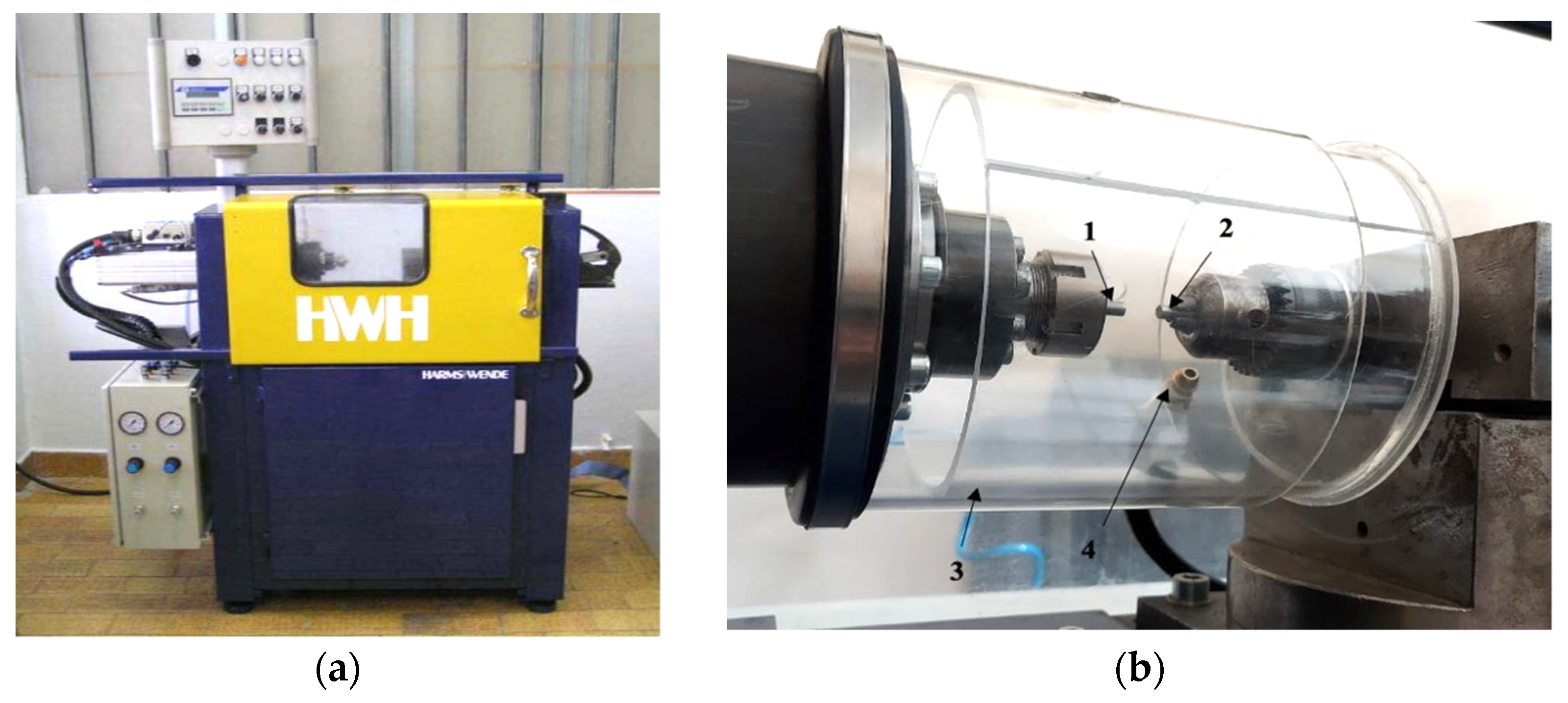
2. Materials and Methods

Rotary friction welding was performed on bars made of technically pure tungsten (ø5 mm) and S355 steel (ø5 on a length of 20 mm). The chemical composition of S355 steel, in accordance with the EN 10204, is presented in Table 1.
A high-speed RSM210 friction welding machine by Harms & Wende GmbH (Hamburg, Germany) was used for processing the friction-welded joints of tungsten and S355 steel (Figure 1a). The machine consists of a few main components, including a precise control system equipped with a welding cycle parameter recorder and a high-speed rotation spindle with a pneumatic piston for creating pressure in the friction phase and the upsetting (forge) phase of the joint formation cycle. The main advantages of the welding machine include the wide operating range of the parameters that can be set—special attention should be paid to achieving a rotational speed above 20,000 RPM—and the ability to set the friction time in milliseconds, which is significantly supported by the efficient braking system.
Figure 1b shows the assembly of the friction welding rods. The rod in the spindle (tungsten) (1) rotates in relation to a common axis with the fixed rod (355 steel) mounted in a vice with a handle (2). The whole friction system of the specimens is enclosed by a shielding gas chamber (3), which enables friction welding in an argon shielding atmosphere (<10 ppm of O2). Table 2 presents a set of high-speed friction welding parameters as results of multi-stage tests of welding and, finally, optimization according to the criterion of interface strength. Cracks of the welded joints during tensile strength tests were located in the tungsten specimen not far (100–300 µm) from the interface. The welding parameters were set according to the criterion of the minimum friction (heating) time, which in turn leads to a large temperature gradient in the narrow zone of the joint formation. The narrow window of parameters was set at a level close to the limit of the possibility of dynamic torsion of a tungsten rod.
Characterization of the microstructure of the friction joint was performed using an optical (OM) and a scanning (SEM) microscope on the cross-section (along the rod axis). The metallographic observations were made under the optical microscope Olympus BX51M coupled with a digital camera and a computer with Olympus Stream Essentials software, with magnification from 50× to 1000×.
SEM studies were carried out on a JEOL JSM-7600F scanning electron microscope equipped with a Schottky emission gun (FEG). Measurements of the hardness distribution across the friction-welded joint in two characteristic areas were carried out using the Vickers method on a LEITZ MINILOAD 8375 hardness tester with a load of 100 g and a test period of 15 s. The sample, after inclusion in epoxy resin, was wet-ground with discs with grain size from 80 to 2500 until the axis of the bars was reached and polished on a polishing cloth with Al2O3 suspension. Finally, the samples were etched with Nital 5%, and in a second step, by Murakami reagent. Hardness measurements were also performed on the sample prepared in this way. For this joint, the instrumented indentation test (IIT) was conducted using Hysitron Ti 950 TriboIndenter with Berkovich tip. Load–depth curves were obtained for points across the friction-welded joint. Indentation hardness (HIT), reduced modulus of the indentation contact (Er) and the elastic part of the indentation work (ηIT) were determined based on the calculations in accordance with ISO 14577-1. A maximum load of 10 mN was used.

3. Results and Discussion

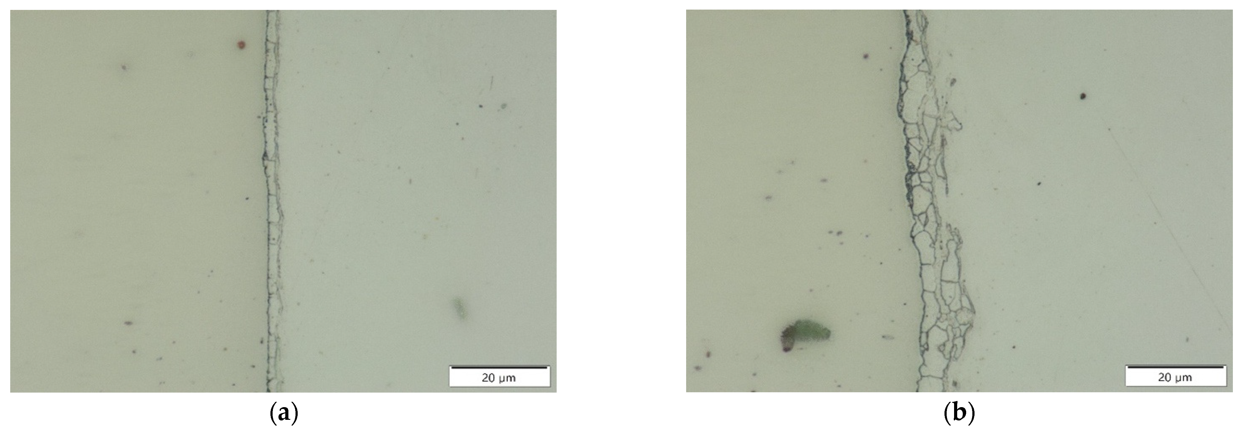
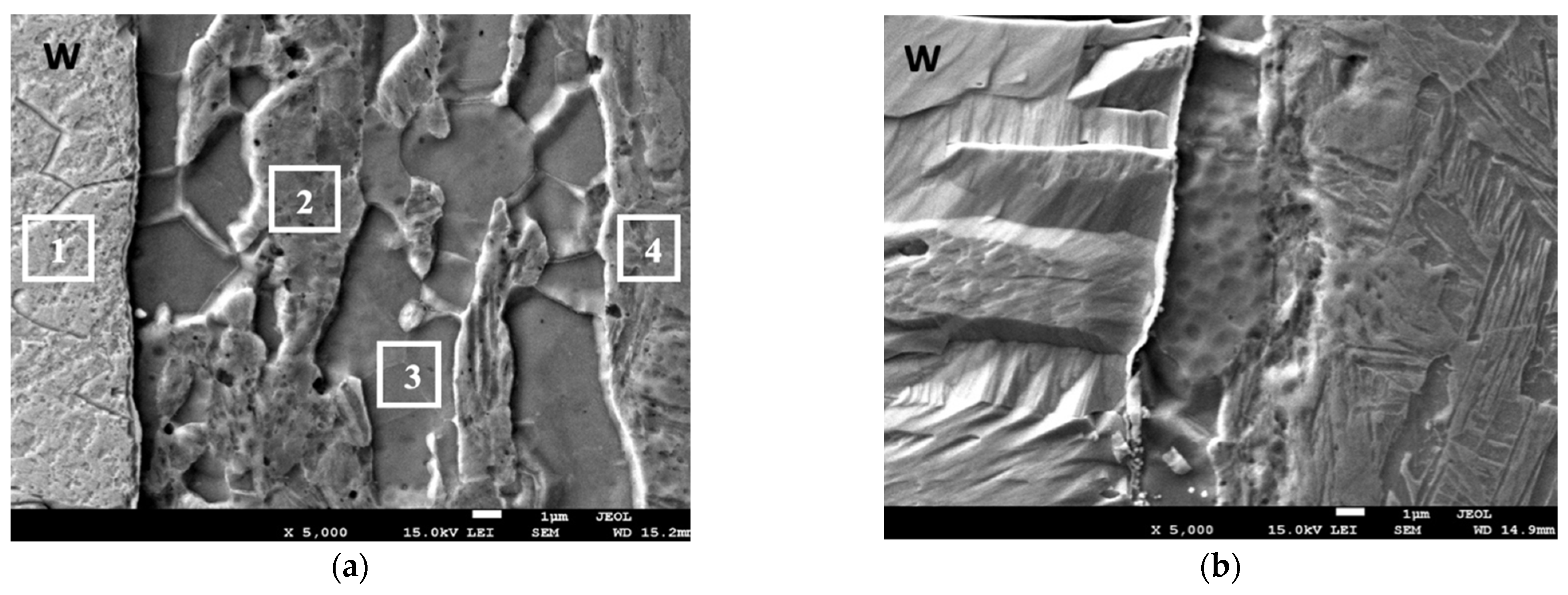
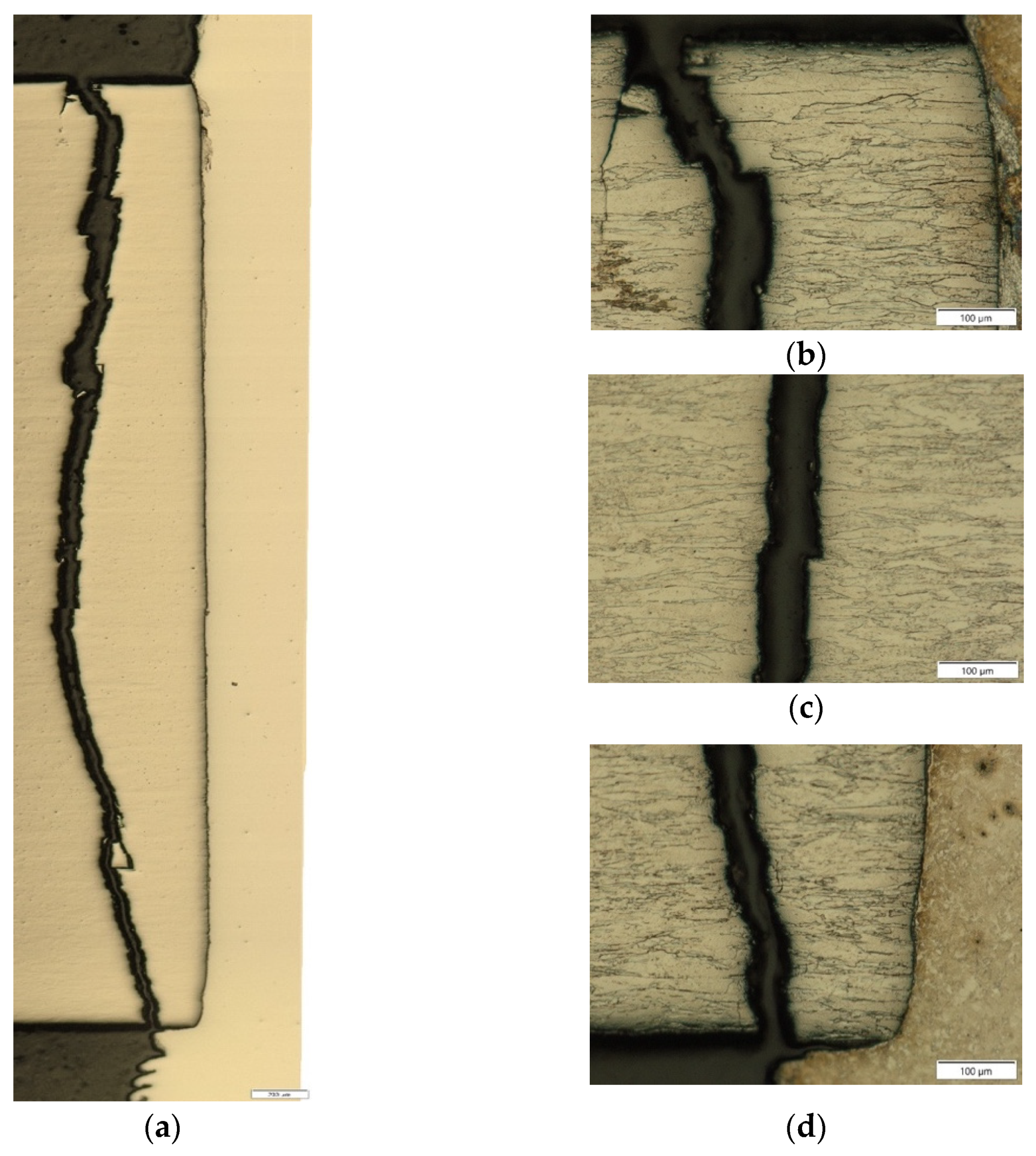
3.1. Observations of the Joint’s Microstructure

Figure 2a shows the welded tungsten–steel S355 joint. A clearly shaped asymmetrical flash is visible on the side of the steel rod. Figure 2a shows the microstructure of the joints in two characteristic areas near the surface of the welded bars (radius ~2 mm), where the linear velocity is the highest and where the most heat is released, and in the second area close to the sample rotation axis, where heating is limited to conduction from neighboring areas, because the linear velocity is close to 0. Figure 3 shows an image of the microstructure obtained without etching for two characteristic areas near the external surface of the bars and near the axis of the joint. A continuous interface is visible between the pair of welded materials. No incompatibilities in the form of voids, cracks or lack of connection were observed at this interface. On the other hand, the transition zone between the tungsten and the steel varies in width along the entire joint. In the axis of the welded bars, this zone is relatively narrow (Figure 3b), while wider in the radius about 2 mm from the axis (Figure 3). These characteristic areas were subjected to detailed microscopic analysis.
Microscopic examinations carried out at a higher magnification revealed the specific microstructure of the tungsten–steel transition zone (Figure 4). It is particularly visible in the area beyond the weld axis, i.e., at the radius where this zone is clearly wider. The microstructure of the tungsten–steel transition zone is two-phase and clearly banded (Figure 4a). The grains of first phase are visible as dark, uniformly colored and irregular, and between them is a second phase with a color and morphology similar to the welded steel.
The surface distributions of W and Fe in these two areas (radius close to the external surface and in the axis of the bars) of the joint (Figure 5 and Figure 6) confirm the dominant share of iron in the transition zone, but with a significant presence of tungsten. Figure 7 and Figure 8 show the linear distribution of elements along a perpendicular line to the W–steel interface. These studies document the participation of tungsten in dark, uniformly colored, irregular grains in the transition zone (Figure 7). The second phase is rich in Fe. The morphology state may be the result of mechanical (plastic) mixing of defragmented grains (on friction surface) of both welded materials and probably combined with the simultaneous occurrence of the phenomenon of diffusion through the interphase boundary in the solid state. Iron dominates in the transition zone. In the weld axis in the transition zone (Figure 8) and in the side part of the joint from the tungsten side (Figure 7), a gentle slope of the concentration profile of both W and Fe was observed. This could be indirect evidence of the interaction of tungsten with iron during the formation of joints.
Figure 9 shows the qualitative analysis of the EDS element share recorded in the characteristic areas of the transition zone marked in Figure 4a. The quantitative share of elements from these areas is presented in Table 3. The obtained results suggest the formation of a new phase in the transition zone at the boundary between tungsten and steel (area 3 in Figure 4a).
Most likely, it is a Fe-based α solid solution. During the friction welding process, in the zone outside of the axis of the joint, this phase defragmentation and ultrafine grains were mixed with grains of plasticized steel. The insignificant proportion of tungsten in area 2 in Figure 4a is a suitable justification of the above statement. On the other hand, in the middle zone (close to the axis), where the linear velocity is the lowest, the formed Fe-based phase is continuous and has not disintegrated (Figure 4b and Figure 8).

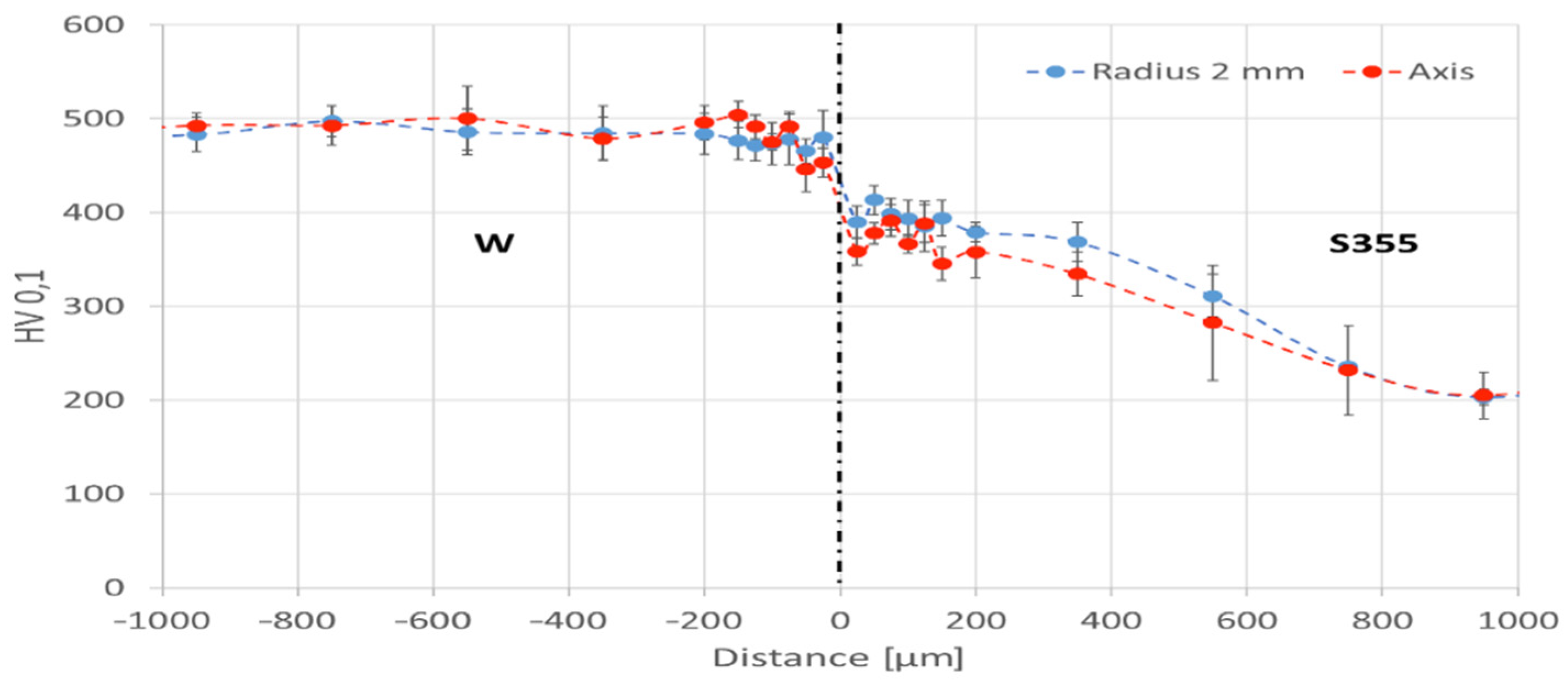
3.2. Hardness Distribution

The hardness HV0.1 measurement was conducted for two areas of the tungsten–S355 steel joint: the zone with ~2 mm radius and the center of the bars’ joint in the axis. For both zones, the microhardness distribution was determined along four measurement lines, from which mean values were calculated. The measurement results as a function of the distance from the W–steel interface are shown in Figure 10.
The average hardness of tungsten in the area out of the joint is about 500 HV0.1. Then, the hardness decreases; the lowest values for the joint on the tungsten side were recorded for the points closest to the interface. The values in this area are from approximately 450 HV0.1 for the axis of the joint to 465 HV0.1 for the edge zone (radius 2 mm). For the initial state of S355 steel, the hardness remains above 200 HV0.1. The value of hardness from the steel side starts to increase from a distance of 600 µm in the interface direction. The highest values of about 400 HV for the S355 steel were recorded at a distance of 25–75 µm from the interface. On the steel side, the grains were strengthened as an effect of plastic deformation and grain defragmentation in the area of the friction plane, while on the tungsten side close to the interface, a decrease in hardness was noted. Although there have been significant changes in the transition zone, the gentle course of the changes in hardness between physically different metals could have a positive stress-mitigating effect.

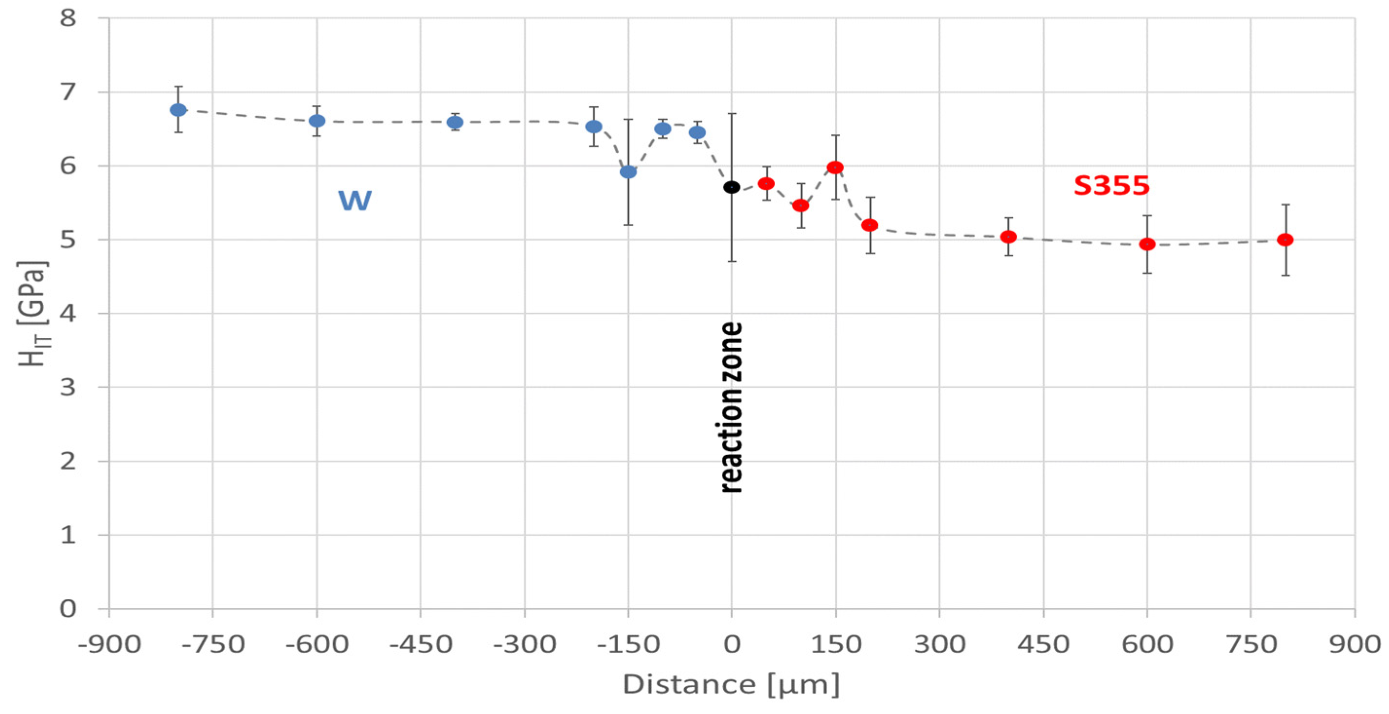
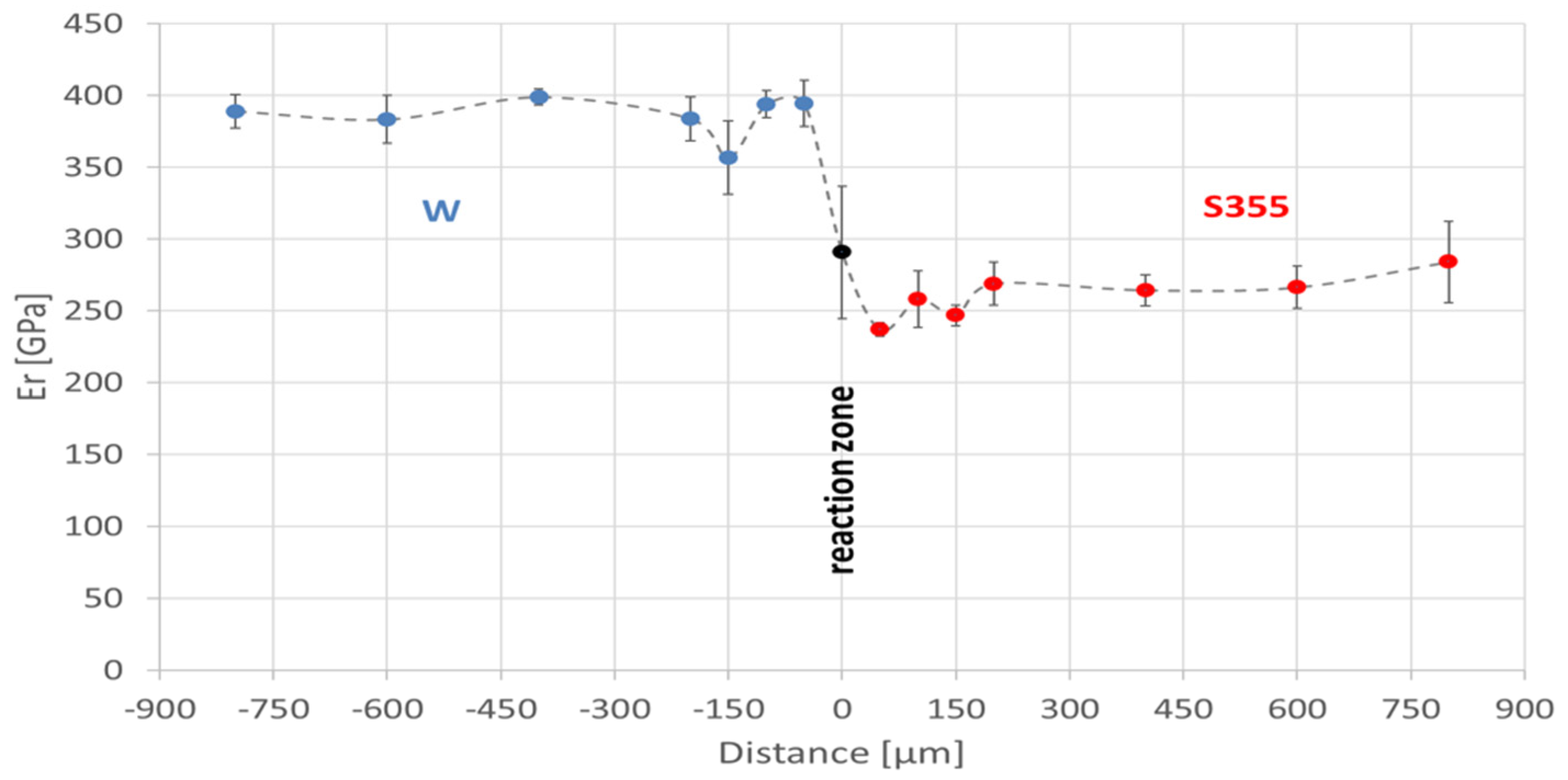
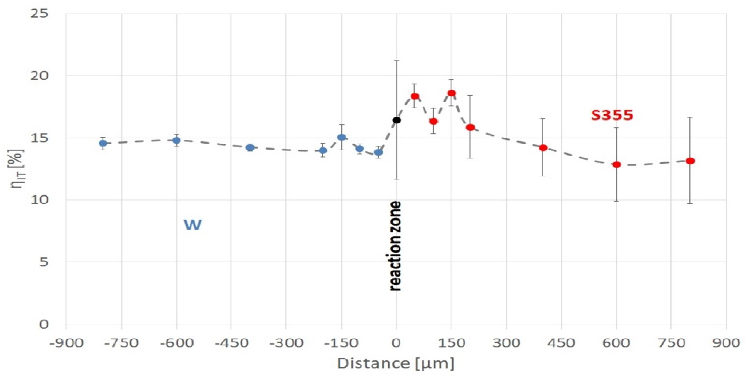
3.3. Instrumented Indentation Test

The HV0.1 hardness distribution revealed changes in the properties of the friction-welded joint. However, due to the size of the indentation and the transition zone, its properties have not been determined precisely enough. Therefore, to determine the properties of the transition zone, the IIT method with a lower test force was used. The results for the “0” area characterize the properties of the reaction zone. Additionally, this method made it possible to obtain values describing the elastic deformation coefficients: Er and the elastic part of the indentation ηIT.
The measurements were conducted in the area containing the transition zone in the axis of the friction-welded bars (Figure 3a). The distribution of mechanical properties was determined along four measurement lines, from which mean values were calculated. The measurement results as a function of the distance from the W–S355 interface are shown in Figure 11, Figure 12 and Figure 13. The depths of the indenter imprints were recorded from 162 to 303 nm. The hardness change tendency in the area near the W–S355 interface was confirmed. The average indentation hardness value of the transition zone was at the same level of steel on the section up to 150 µm from the border with tungsten. This value was ~5.7 GPa. At a distance of 200 µm from the interface, the indentation hardness value of the steel drops to about 5 GPa. The values for tungsten ranged from 6.5 to 6.8 GPa. The exception was the area 150 µm away from the interface, for which a value of ~5.9 GPa was recorded.
Er values for tungsten were 390 GPa. The area 150 µm away from the interface is an exception, for which a value of just over 350 GPa was recorded. For S355, the reduced modulus values ranged from 237 for the area 50 µm away from the interface to 284 GPa for the 800 µm distance. By contrast, Er for the reaction zone was 291 GPa.
While making imprints in the friction-welded sample, the plastic deformation work (Wplastic) was dominant. For tungsten, ηIT was about 14–15%, while for steel, it was about 13%. In the reaction zone, the Welastic part was 16%. It remained at an elevated level (14–18%) in the friction-welded zone at 400 µm from the interface on the S355 side.
The reaction zone was formed from the combination of W–S355 materials and is characterized by intermediate properties between them. Compared to W, lower indentation hardness, reduced modulus and a greater part of plastic deformation work during the indentation process were recorded. However, in relation to steel, higher values of HIT, Er and ηIT were registered. This tendency was also present farther away from the W–S355 interface. The gradual changes in the measured properties (HV0.1, HIT, Er and ηIT) are visible at the following distances from the interface: 550 µm for steel, and 150 µm for tungsten. It was also observed that the results for the reaction zone showed the greatest dispersion. This proves that the dynamic joining process caused greater heterogeneity in this area in relation to the base materials.

3.4. Tensile Strength of Welded Joints

The ultimate tensile strength of the W–steel welded specimens was measured in a calibrated universal tensile testing machine with a capacity of 40 tons, a type ZD-40 machine (Germany), at a rate of 1.5 mm/min ram speed. The asymmetrical flash of friction-welded joints on the side of the steel was not removed before tensile tests. Figure 14 shows the test specimen with crack localization on the tungsten side of the joints close to the interface.
The range of recorded UTS values for the population of 20 samples was relatively wide, from 150 to 330 MPa. In each case, the cracks were on the tungsten side close to the interface. The average strength value of the joint was significantly lower than the nominal values characteristic for tungsten. In the structure of the joint on the tungsten side, no instances of changes that could be responsible for this weakening were observed. The reason may be the high level of residual stresses [30] inherent in tungsten and steel joints.

4. Conclusions

The microstructure, hardness and tensile strength of joints between tungsten and S355 mild steel after high-speed rotary friction welding were investigated, with a focus on changes in physical properties, phase and chemical compositions at the interface. The following main results were obtained:
  • Friction welding of tungsten to S355 steel was successfully carried out directly and without any heat treatment under a shielding gas atmosphere. The maximum friction-welded joint strength of 330 MPa is about 30% of the tungsten base material. The average value of the strength of the joint was significantly lower than the nominal values characteristic for tungsten.
  • In the structure of the joint on the tungsten side, no instances of changes that could be responsible for this weakening were observed. The reason may be the high level of residual stresses inherent in tungsten and iron alloy joints.
  • The microstructure of friction welds consisted of fine equiaxed grains due to dynamic recrystallization. Moreover, plastic deformation in the direction of the flash is visible mainly on the steel side.
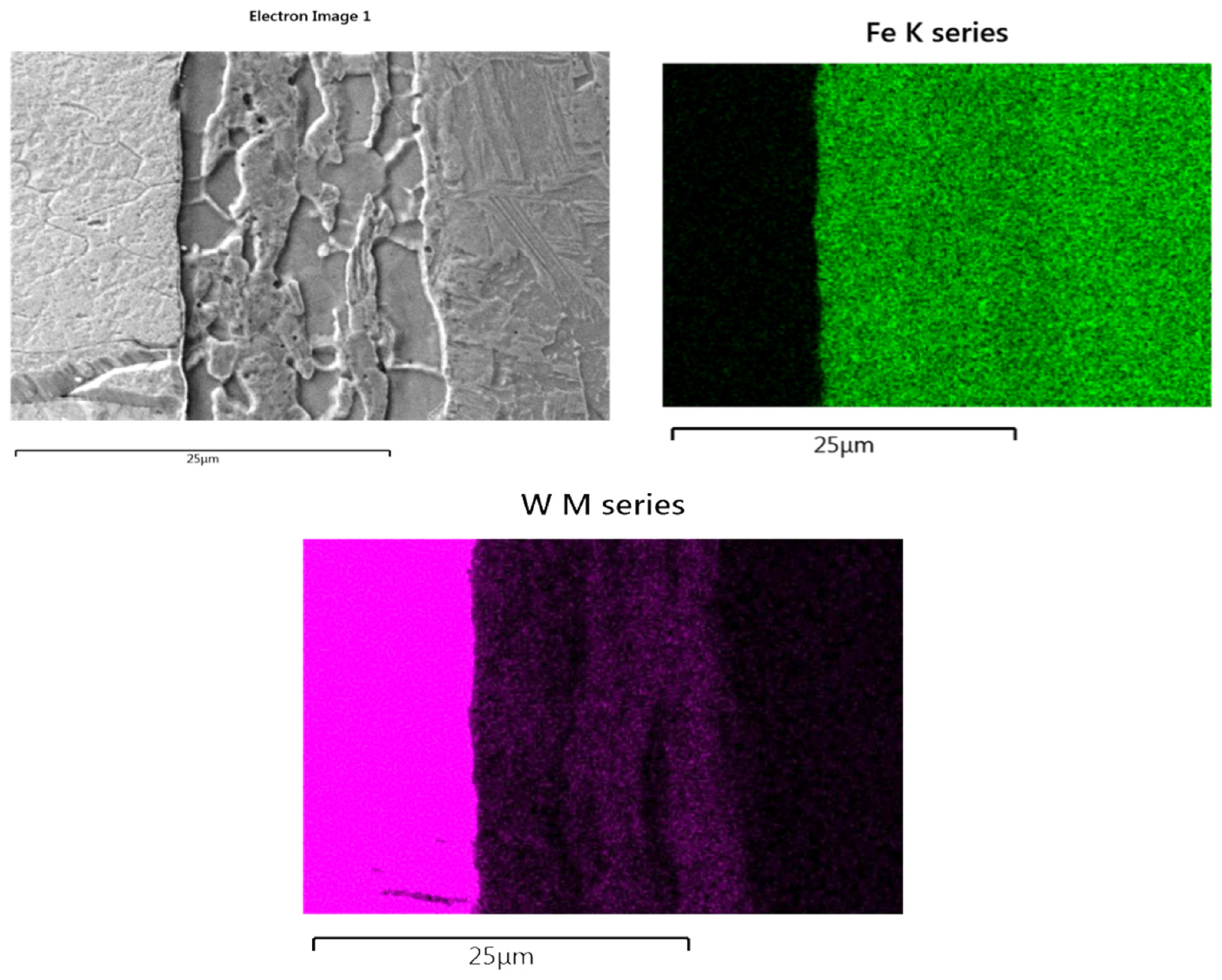
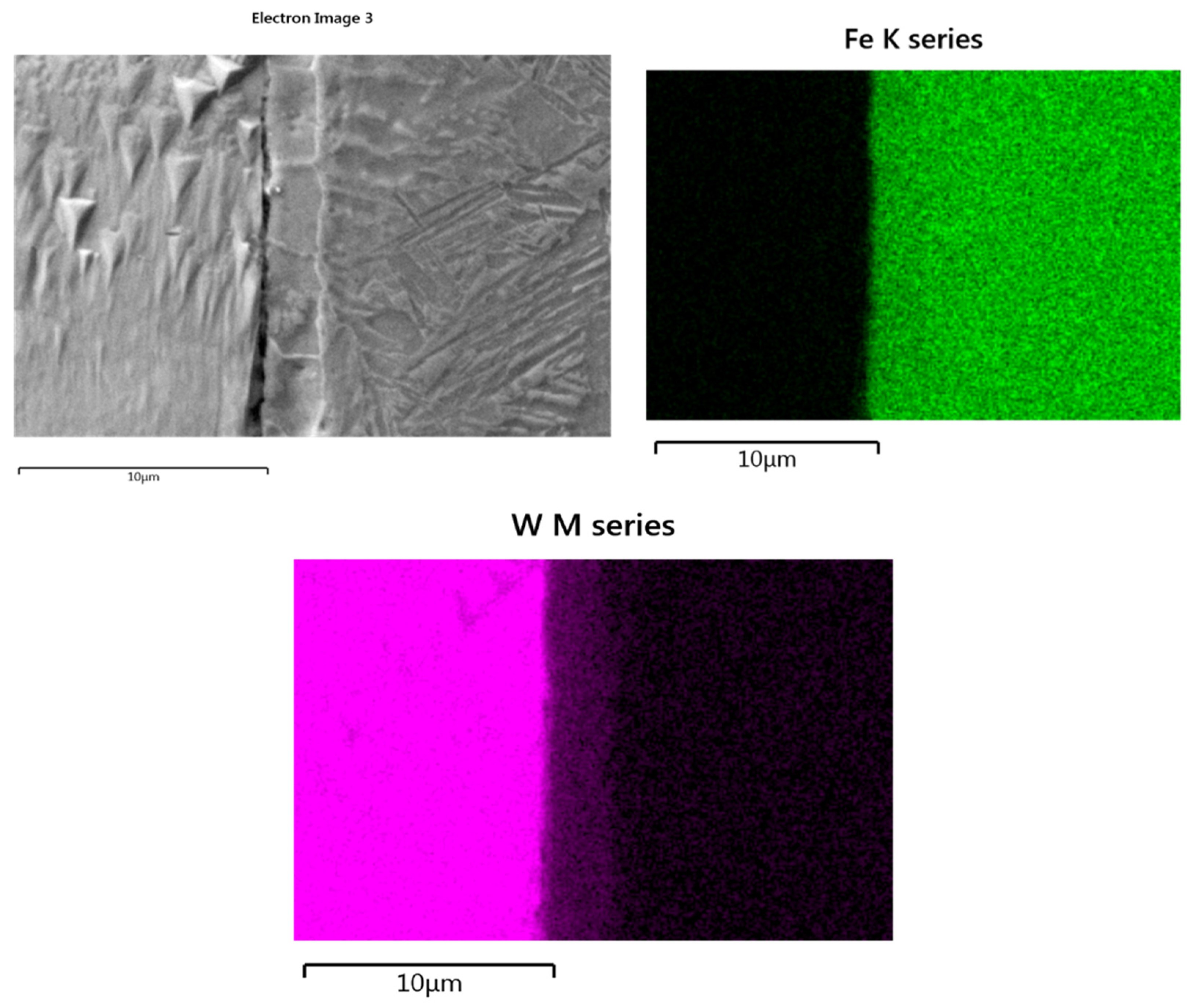
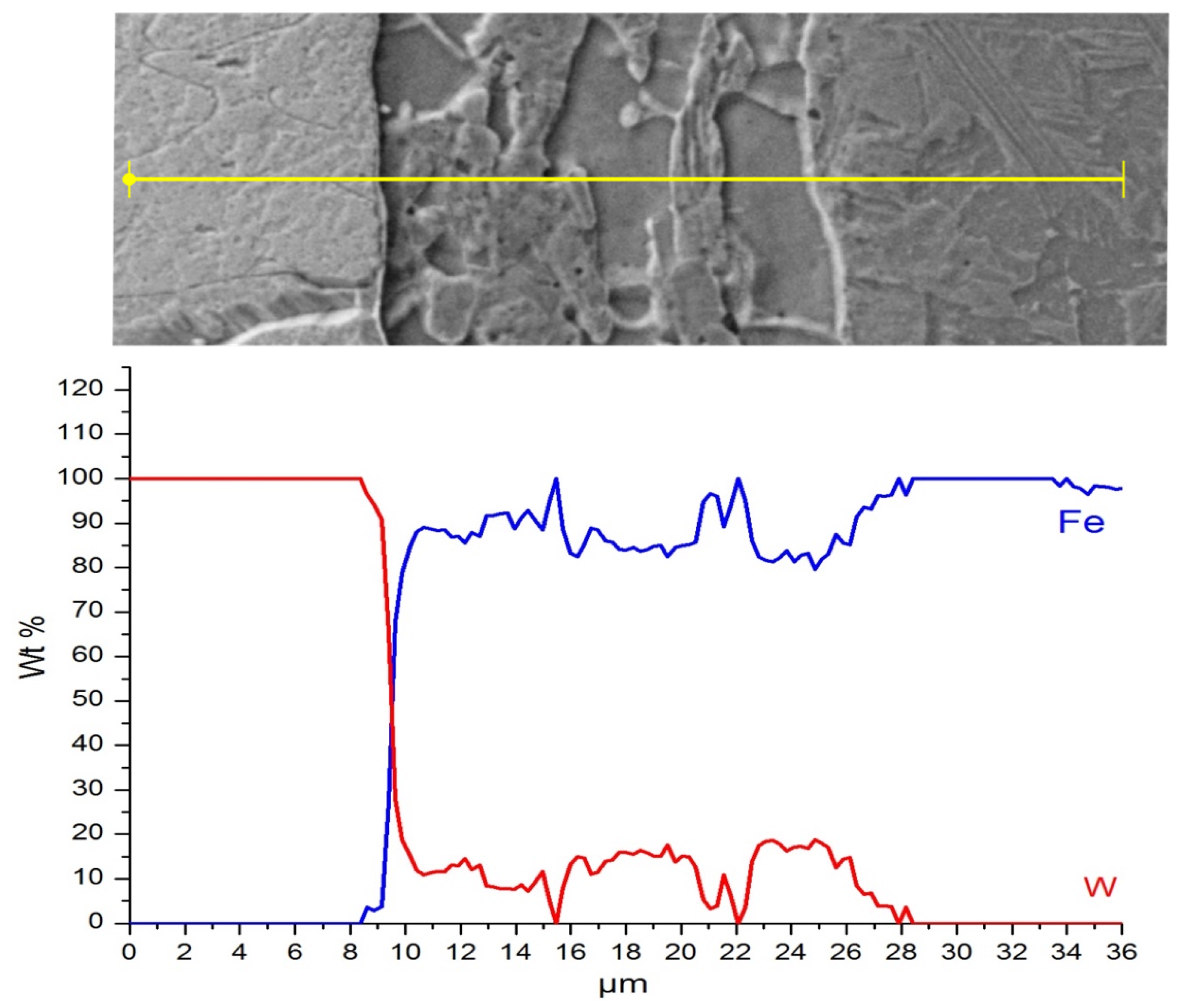
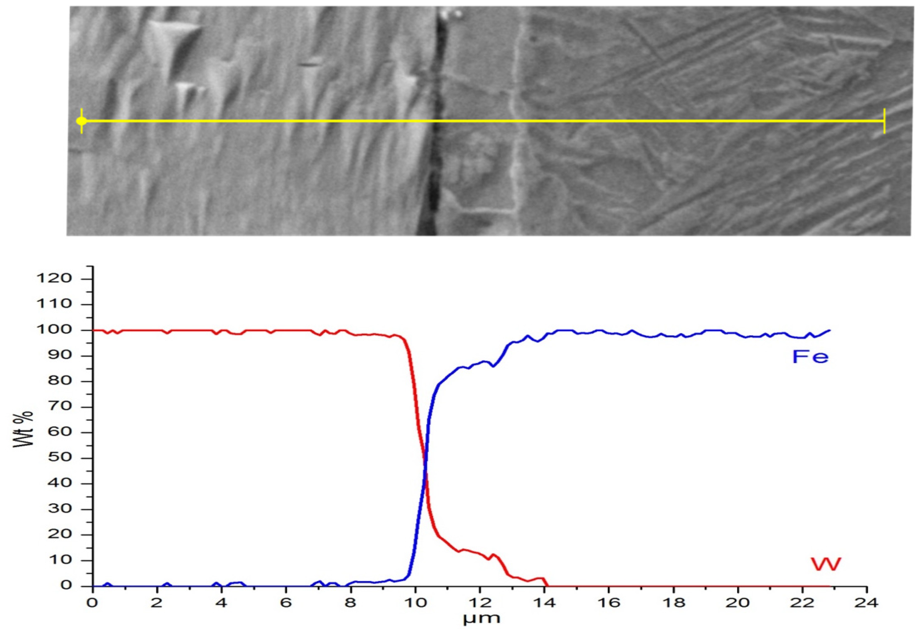
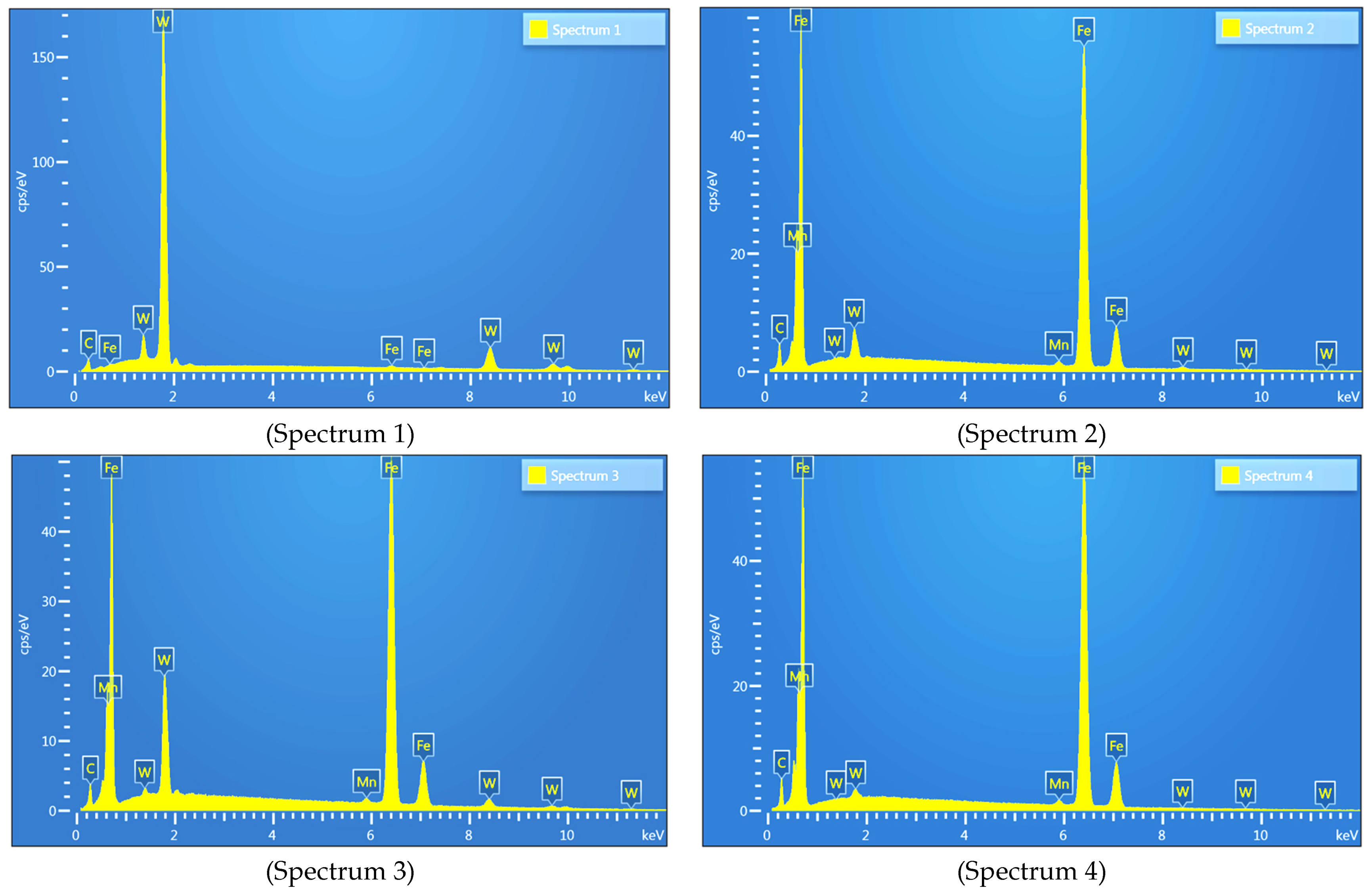
  • EDS-SEM maps and scan line analyses across the interface did not confirm the diffusion of tungsten to the iron alloy side. However, the EDS-SEM point analysis indicated a slight amount of tungsten in the Fe matrix close to the interface.
  • On the basis of EDS and fracture observation, it can be concluded that the nature of friction welding of dissimilar joint is non-equilibrium based on deep plastic deformation without visible diffusive processes in the interface zone.
  • The phase boundary of W–steel is not the weakest element of the joint; fractures during the tensile test propagated through tungsten grains close to the interface.
  • The tungsten was weakened by the welding process close to the W–steel interface.

Author Contributions

Conceptualization, B.S. and T.C.; methodology, T.C.; software, M.B. (Mariusz Bober); validation, M.B. (Mariusz Bober), P.K. and M.B. (Michał Baranowski); formal analysis, B.S.; investigation, T.C. and M.K.; resources, P.K.; data curation, M.B. (Michał Baranowski); writing—original draft preparation, T.C., B.S. and M.K.; writing—review and editing, T.C. and M.K.; supervision, T.C. All authors have read and agreed to the published version of the manuscript.

Funding

This research received no external funding.

Conflicts of Interest

The authors declare no conflict of interest.

References

  1. Tzeng, C.J.; Yang, Y.K.; Hsieh, M.H.; Jeng, M.C. Optimization of Wire Electrical Discharge Machining of Pure Tungsten Using Neural Network and Response Surface Methodologyg. Proc. Inst. Mech. Eng. Part B J. Eng. Manuf. 2011, 225, 841. [Google Scholar] [CrossRef]
  2. Gulbinowicz, Z.; Swiercz, R.; Oniszczuk-Swiercz, D. Influence of Electrical Parameters in Electro Discharge Machining of Tungsten Heavy Alloys on Surface Texture Properties. AIP Conf. Proc. 2018, 2017, 020007. [Google Scholar]
  3. Jamrozik, W.; Górka, J.; Kik, T. Temperature-Based Prediction of Joint Hardness in TIG Welding of Inconel 600, 625 and 718 Nickel Superalloys. Materials 2021, 14, 442. [Google Scholar] [CrossRef] [PubMed]
  4. Giri, A.; Pandey, C.; Mahapatra, M.M. Achieving Optimized Tungsten Inert Gas Butt Welding Conditions of Thin Cold Rolled Steel Sheets by Response Surface Methodology and Artificial Neural Networks. Proc. Inst. Mech. Eng. Part E J. Process Mech. Eng. 2018, 232, 459–470. [Google Scholar] [CrossRef]
  5. Skowrońska, B.; Szulc, J.; Bober, M.; Baranowski, M.; Chmielewski, T. Selected Properties of RAMOR 500 Steel Welded Joints by Hybrid PTA-MAG. J. Adv. Join. Process. 2022, 5, 100111. [Google Scholar] [CrossRef]
  6. Skoczylas, P.; Goroch, O.; Gulbinowicz, Z.; Penkul, A. The Effect of Cold Swaging of Tungsten Heavy Alloy with the Composition W91-6Ni-3Co on the Mechanical Properties. Materials 2021, 14, 7300. [Google Scholar] [CrossRef]
  7. Bachurina, D.; Suchkov, A.; Kalin, B.; Sevriukov, O.; Fedotov, I.; Dzhumaev, P.; Ivannikov, A.; Leont’eva-Smirnova, M.; Mozhanov, E. Joining of Tungsten with Low-Activation Ferritic–Martensitic Steel and Vanadium Alloys for Demo Reactor. Nucl. Mater. Energy 2018, 15, 135–142. [Google Scholar] [CrossRef]
  8. Bachurina, D.; Vorkel, V.; Suchkov, A.; Gurova, J.; Ivannikov, A.; Penyaz, M.; Fedotov, I.; Sevryukov, O.; Kalin, B. Overview of the Mechanical Properties of Tungsten/Steel Brazed Joints for the Demo Fusion Reactor. Metals 2021, 11, 209. [Google Scholar] [CrossRef]
  9. Winiczenko, R.; Goroch, O.; Krzyńska, A.; Kaczorowski, M. Friction Welding of Tungsten Heavy Alloy with Aluminium Alloy. J. Mater. Process. Technol. 2017, 246, 42–45. [Google Scholar] [CrossRef]
  10. Scapin, M. Mechanical Characterization and Modeling of the Heavy Tungsten Alloy IT180. Int. J. Refract. Met. Hard Mater. 2015, 50, 258–268. [Google Scholar] [CrossRef]
  11. Kruszewski, M.J.; Ciupiński, Ł.; Rosiński, M.; Michalski, A.; Kurzydłowski, K.J. Pulse Plasma Sintering of a Tungsten/Steel Divertor Module. Fusion Eng. Des. 2013, 88, 2573–2576. [Google Scholar] [CrossRef]
  12. Bachurina, D.; Suchkov, A.; Filimonov, A.; Fedotov, I.; Savelyev, M.; Sevryukov, O.; Kalin, B. High-Temperature Brazing of Tungsten with Steel by Cu-Based Ribbon Brazing Alloys for DEMO. Fusion Eng. Des. 2019, 146, 1343–1346. [Google Scholar] [CrossRef]
  13. Ambroziak, A. Friction Welding of Titanium-Tungsten Pseudoalloy Joints. J. Alloys Compd. 2010, 506, 761–765. [Google Scholar] [CrossRef]
  14. Włosiński, W.K. The Joining of Advanced Materials; Oficyna Wydawnicza Politechniki Warszawskiej: Murzasichle, Poland, 1999. [Google Scholar]
  15. Krajewski, A. Joining of Si3N4 to Wear-Resistant Steel by Direct Diffusion Bonding. J. Mater. Processing Technol. 1995, 54, 103–108. [Google Scholar] [CrossRef]
  16. Senkara, J.; Włosinski, W.K. Surface Phenomena at the Interfaces of the Tungsten-Liquid Cu-Sb Alloy System. J. Mater. Sci. 1985, 20, 3597–3604. [Google Scholar] [CrossRef]
  17. Golański, D.A.; Grześ, J. The Numerical Analysis of Residual Stresses in Surface Layers Deposited by Brush-Plating Method. Proc. Inst. Mech. Eng. Part B J. Eng. Manuf. 2006, 220, 429–437. [Google Scholar] [CrossRef]
  18. Mirski, Z.; Piwowarczyk, T. Analysis of Adhesive Properties of B2 Hardmetal Surface. Arch. Civ. Mech. Eng. 2009, 9, 93–104. [Google Scholar] [CrossRef]
  19. Mirski, Z.; Rózański, M. Diffusion Brazing of Titanium Aluminide Alloy Based on TiAl (γ). Arch. Civ. Mech. Eng. 2013, 13, 415–421. [Google Scholar] [CrossRef]
  20. Krajewski, A.; Klekot, G.; Cybulak, M.; Kołodziejczak, P. A Novel Method of Supporting the Laser Welding Process with Mechanical Acoustic Vibrations. Materials 2020, 13, 4179. [Google Scholar] [CrossRef]
  21. Janeczek, A.; Tomków, J.; Fydrych, D. The Influence of Tool Shape and Process Parameters on the Mechanical Properties of Aw-3004 Aluminium Alloy Friction Stir Welded Joints. Materials 2021, 14, 3244. [Google Scholar] [CrossRef]
  22. Khan, N.Z.; Siddiquee, A.N.; Khan, Z.A.; Badruddin, I.A.; Kamangar, S.; Maqbool, A. Improvement in Joint Efficiency with High Productivity and Narrow Weld Formation in Friction Stir Welding. Proc. Inst. Mech. Eng. Part E J. Process Mech. Eng. 2022, 236, 383–393. [Google Scholar] [CrossRef]
  23. Nu, H.T.M.; Loc, N.H.; Minh, L.P. Influence of the Rotary Friction Welding Parameters on the Microhardness and Joint Strength of Ti6Al4V Alloys. Proc. Inst. Mech. Eng. Part B J. Eng. Manuf. 2021, 235, 795–805. [Google Scholar] [CrossRef]
  24. Skowrońska, B.; Chmielewski, T.; Kulczyk, M.; Skiba, J.; Przybysz, S. Microstructural Investigation of a Friction-Welded 316l Stainless Steel with Ultrafine-Grained Structure Obtained by Hydrostatic Extrusion. Materials 2021, 14, 1537. [Google Scholar] [CrossRef] [PubMed]
  25. Winkler, M.; Gawert, C.; Bähr, R.; Jüttner, S.; Trommer, F. Investigation of the Friction Weldability of an AlSi10MnMg-Alloy Reinforced with 30 Vol.-% Silicon Carbide Particles with the Adequate Monolithic Material. J. Adv. Join. Processes 2022, 5, 100101. [Google Scholar] [CrossRef]
  26. Skowrońska, B.; Chmielewski, T.; Pachla, W.; Kulczyk, M.; Skiba, J.; Presz, W. Friction Weldability of UFG 316L Stainless Steel. Arch. Metall. Mater. 2019, 64, 1051–1058. [Google Scholar] [CrossRef]
  27. Iwaszko, J.; Kudła, K. Effect of Friction Stir Processing (FSP) on Microstructure and Hardness of AlMg10/SiC Composite. Bull. Pol. Acad. Sci. Tech. Sci. 2019, 67, 185–192. [Google Scholar] [CrossRef]
  28. Takeoka, N.; Tsuchida, T.; Matsuda, T.; Ogura, T.; Ohashi, R.; Hirose, A. Analysis of Mechanical Properties of Dissimilar Material Joint Using Scrubbing Refill Friction Stir Spot Welding. J. Adv. Join. Process. 2022, 5, 100112. [Google Scholar] [CrossRef]
  29. Ou, Y.; Deng, Y.; Zhang, W.; Zhao, Y.; Zeng, J. Effect of Friction Time on Heat Distribution, Material Flow, and Microstructure of Friction Welding of Dissimilar Steels. Proc. Inst. Mech. Eng. Part L J. Mater. Des. Appl. 2022, 14644207221117671. [Google Scholar] [CrossRef]
  30. Cai, Q.; Liu, W.; Ma, Y.; Liu, H. Microstructure, Residual Stresses and Mechanical Properties of Diffusion Bonded Tungsten-Steel Joint Using a V/Cu Composite Barrier Interlayer. Int. J. Refract. Met. Hard Mater. 2015, 48, 312–317. [Google Scholar] [CrossRef]
Figure 1. High-speed welding machine. (a) General view. (b) Assembly of samples to be welded in special argonium atmosphere chamber: (1) rotating sample, (2) stationary sample, (3) atmosphere chamber, (4) shielding gas supply nozzle.
Applsci 12 09034 g001
Figure 2. Microstructure of a friction-welded joint (tungsten + S355) (a); in two characteristic areas, (b) near the surface of the welded bars (~2 mm radius), (c) close to the sample rotation axis.
Applsci 12 09034 g002
Figure 3. OM microstructure of tungsten–S355 steel friction-welded joint in longitudinal section: (a) in the axis of the welded bars, (b) at ~2 mm radius of the welded bars sample (not etched).
Applsci 12 09034 g003
Figure 4. SEM microstructure of friction-welded W with S355 steel bars: (a) zone in ~2 mm radius of specimens; (b) in the axis of the bars’ rotation.
Applsci 12 09034 g004
Figure 5. Surface distribution of elements at the interface in the zone with ~2 mm radius of bars of W–steel welded joints.
Applsci 12 09034 g005
Figure 6. Surface distribution of elements at the interface in the axis of W–steel welded joints.
Applsci 12 09034 g006
Figure 7. Linear distribution of Fe and W in cross-section of the interface of the joints, outside of the bars’ rotary axis.
Applsci 12 09034 g007
Figure 8. Linear distribution of Fe and W in cross-section of the interface of the joints, in the welded bars’ rotary axis.
Applsci 12 09034 g008
Figure 9. EDS spectrum recorded in the characteristic areas of the W–steel transition zone indicated in Figure 4.
Applsci 12 09034 g009
Figure 10. The hardness distribution as a function of the distance from the tungsten–S355 steel interface.
Applsci 12 09034 g010
Figure 11. The indentation hardness distribution as a function of the distance from the tungsten–S355 steel interface.
Applsci 12 09034 g011
Figure 12. The distribution of reduced modulus of the indentation contacts as a function of the distance from the tungsten–S355 steel interface.
Applsci 12 09034 g012
Figure 13. The distribution of the elastic part of the indentation work as a function of the distance from the tungsten–S355 steel interface.
Applsci 12 09034 g013
Figure 14. Macrograph in fracture area of (a) the friction-welded joint (tungsten + S355), non-etched; (b,d) micrograph of the fracture at the edge and axis (c) of the bars with higher magnification.
Applsci 12 09034 g014
Table 1. Chemical composition (wt %) of S355 steel based on manufacturer specification—3.2 type quality certificate according to EN 10204.
C.SiMnPSCrNiMoAlVCuTiFe
0.1710.2471.0050.0260.00590.0380.0200.0030.0320.0030.0100.0026rest
Table 2. Process parameters of high-speed friction welding of tungsten + S355 steel.
Process ParameterValue
Spindle rotational speed (in the friction phase) [RPM]10,000
Friction phase duration [ms]900
Forge phase duration [ms]2000
Pressure on the front of the specimens in the friction phase [MPa]110
Pressure on joint surface of the samples in the forge (upset) phase [MPa]137.5
Shielding gas flow argonium [l/min]18
Table 3. The quantitative share of elements in the areas of the reaction zone marked in Figure 4a.
Spectrum LabelSpectrum 1Spectrum 2Spectrum 3Spectrum 4
Mn-1.100.881.09
Fe1.0293.7081.7197.91
W98.985.1917.401
Total100100100100
Publisher’s Note: MDPI stays neutral with regard to jurisdictional claims in published maps and institutional affiliations.

