1. Introduction
The importance of remote collaboration has increased as we experienced the COVID-19 pandemic. Remote collaboration is the ability to engage as a team from anywhere without a physical meeting. Remote collaboration has now become a standard in many industries. Especially remote collaborative teamwork is vital to any organization’s growth and progress in the Architecture, Engineering, and Construction (AEC) industry. Since the AEC industry is mainly operated on-site in a team unit, remote collaboration is even more necessary. Learning more about remote collaboration can lead to increased productivity.
Building Information Modeling (BIM) is fundamentally changing the paradigm of methodologies for managing design data in the AEC industry [
1]. BIM as a digital information system, n-dimensional design with attribute information of each design member, is used to efficiently share, utilize, and manage this information by various participants in a construction project [
2,
3]. Based on these benefits, BIM as a data hub provides a potential for remote collaboration among participants in a construction project through all stages, including design, construction, and maintenance divisions. BIM has the potential to assist collaboration by sharing building element information between different applications and users throughout the lifecycle of the facility [
4]. Two-dimensional drawings are usually used, and the participants of each division modify and use them for their own purposes in the AEC industry. As a result, communication among participants from different divisions was limited, and data compatibility was not guaranteed. BIM also gives us on-monitor 3D models but does not meet the demand for scaling to real-world scales [
5].
Extended reality (XR) technology provides a solution to overcome these limitations of BIM. XR is a generic term for immersive technologies, including virtual reality (VR), augmented reality (AR), and Mixed Reality (MR) technologies. According to the degree of experience that blurs the boundary between the real and virtual world, it is classified into VR, AR, and MR. This study focuses on MR, where physical and digital objects are presented together, which has tremendous potential to improve AEC efficiency and productivity [
6]. MR-based design reviews can effectively communicate information to the client compared with 2D media.
This study challenges to increase communication effectiveness and efficiency between a field operator and office manager on a construction site by employing BIM and MR. As mentioned above, higher productivity improvement can be expected through effective remote collaboration on a construction site. Since experts from various fields, such as structural engineers, constructors, electrical engineers, and mechanical engineers, work together for a construction project, it is important to communicate properly among them. This is because, in many cases, it is difficult to understand the other person, no matter how well they express it in words. In other words, if the field operator sees the artifacts of the site and the BIM object to be checked by the office manager are displayed on the same display simultaneously, communication efficiency will be greatly increased.
This study aims to develop an MR-based remote collaboration system that can interactively move BIM objects. This system works in the Internet environment and supports communication between field managers and office managers. This system allows the office manager to see the field operator’s view with the virtual BIM objects superimposed on it. The field operator can also move BIM objects around with finger-pointing cues. Through this, the communication effectiveness and efficiency of the two collaborators can be improved. This system consists of (1) Field Operator System (FOS), (2) Communication Server, and (3) Office Manager System (OMS). FOS is a system for the field operator who inspects the construction site while walking around the site and is composed of an HMD and a mobile application. The Communication Server serves as a connector between the FOS and OMS. Finally, the OMS is a system for a manager at a remote office.
2. Literature Review
Mixed Reality is a term proposed by Milgram and Kishino in 1994 [
7]. They introduced the concept of Mixed Reality by proposing a reality–virtual continuum. Assuming that the left extreme is the real environment and the right extreme is the virtual environment, AR is defined as augmented virtual objects in the real environment, and Augmented Virtuality is defined as augmented real objects in the virtual environment. Mixed Reality means mixing AR and Augmented Virtuality (AV) technologies.
MR provides users with close-to-reality visualization by superimposing 3D virtual objects in the real world. MR technology has been mainly used to visualize BIM content for communication among project stakeholders in the AEC industry. Chalhoub and Ayer (2018) conducted a quasi-experiment that compared the performance of electrical construction personnel using traditional paper versus MR and concluded that MR enabled a significantly higher productivity rate, reduced the time required to understand the design, and led to fewer errors during the assembly process [
6]. Carrasco and Chen (2021) evaluated the design review based on MR and 2D drawings by conducting a comparison experiment and found that MR-based design review can improve participants’ level of understanding by 15% compared to 2D drawing verification [
8]. Prabhakaran et al. (2020) proposed a method for the application of MR in design coordination and presented a prototypical model [
9]. They found that MR improves design productivity and quality. Naticchia et al. (2020) proposed a framework that supports on-site operations during the facility management stage using BIM, MR, and a cloud-based system [
10]. Fonnet et al. (2017) presented a framework for an MR application to improve building inspector work for historical and cultural buildings [
11]. Wang et al. (2014) presented the rationales for the on-site information system for construction site activities and combined the methods of configuring BIM and AR prototypes [
12]. They concluded that this solution could address low productivity in retrieving information, the tendency to commit an assembly error, and low communication efficiency. Nguyen et al. (2022) developed a BIM-based MR application to inspect bridges and confirmed that bridge inspection work could be improved [
13]. Raimbaud et al. (2019) proposed an MR application based on BIM data and drone videos for off-site construction supervision [
14]. Regarding construction education, MR was effectively used in construction education [
15,
16].
Remote collaboration begins when physically distant people share the same visual or auditory information. Various MR applications have been proposed for remote collaboration because MR provides excellent visual effects. Most remote collaboration studies are summarized as an effort to evaluate the effectiveness of communication cues such as point, sketch, and hand gestures. Teo et al. (2019) developed a hybrid prototype of 360-degree live video and 3D virtual reconstruction for remote collaboration and found that participants performed significantly better on collaborative search tasks in a 360-degree live video [
17]. Bai et al. (2020) presented an MR remote collaboration system that enables a worker to share a live 3D panorama of the surroundings with a remote expert [
18]. They found that combining gaze and gesture cues provided a stronger sense of co-presence than when using gaze cues alone. Kim et al. (2020) evaluated the effects of several visual communication cues (e.g., pointer, sketch, and hand gesture) through a user study and found that the hand gesture cue is the main visual communication cue, and the sketch cue helps hand gesture cue [
19]. Yang et al. (2020) presented an MR remote collaboration system that shares spatial auditory and visual cues [
20]. They found that the spatialized remote expert’s voice and auditory beacons enabled local workers to find small occluded objects with significantly stronger spatial perception.
On the other hand, few studies on remote collaboration using MR in the AEC industry have been studied. Ammari and Hammad (2019) presented the MR remote collaboration development framework for facilities management and developed a prototype system [
4]. They confirmed that the task efficiency was improved through an applicability test. Wang and Dunston (2011) tested the capabilities of the MR systems in a realistic environment and collaborative tasks against prevalent methods [
21]. They found that the MR system significantly reduced the performance time for the collaborative design error detection task.
Remote collaboration technology in the AEC industry is relatively underdeveloped compared to the manufacturing industry. The reason may be that 3D BIM design has become common only recently. It is not easy to communicate enough with 2D design drawings. What is encouraging is that 3D BIM design is becoming more common in recent years. This study aims to develop a remote collaboration system based on BIM and MR, which can contribute to remote collaboration, an area still not sufficiently studied in the AEC industry.
3. System Design and Development
3.1. Overall System Architecture
The developed system in this study, the Mixed Reality-based Remote Collaboration System (MR2CS), consists of three unit systems: (1) Field Operator System (FOS), (2) Communication Server, and (3) Office Manager System (OMS).
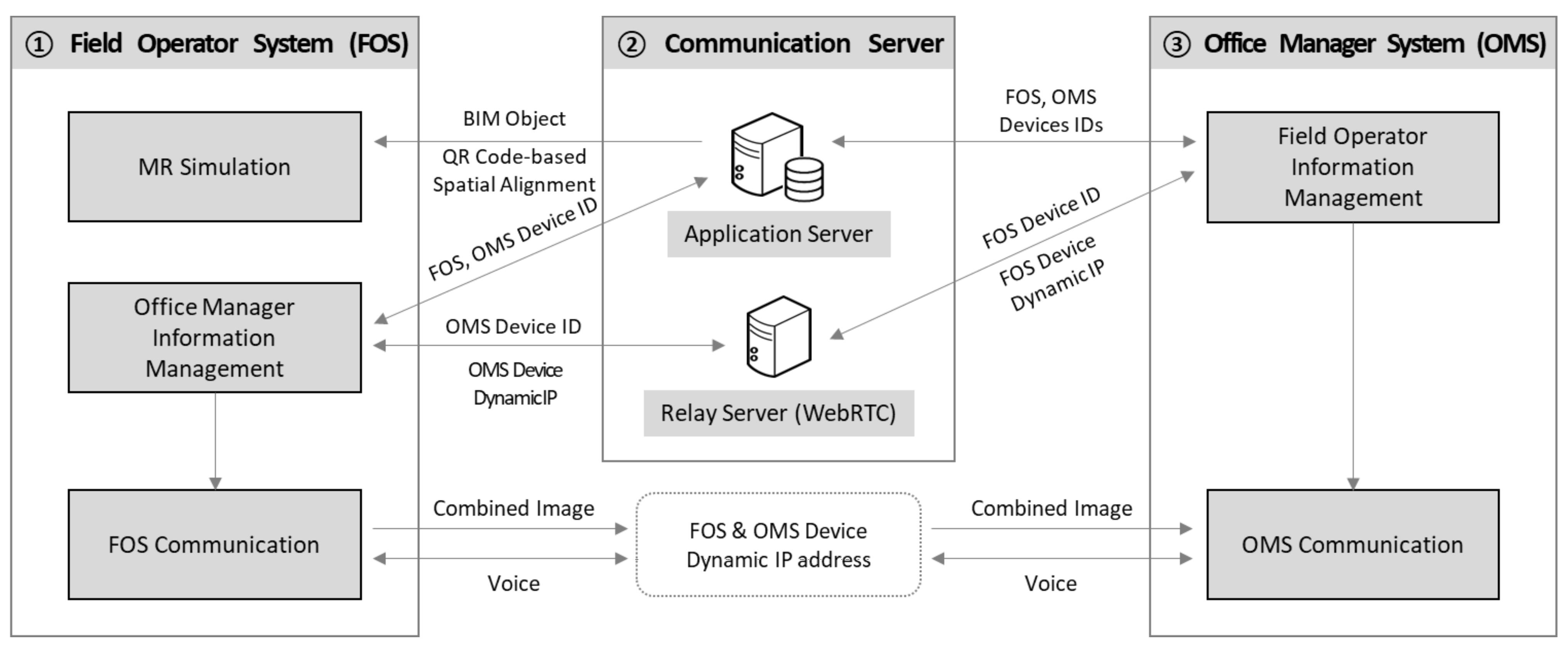
Figure 1 shows the overall architecture of MR2CS. First, FOS has been developed based on HoloLens 2, MR smart glasses developed by Microsoft (Redmond, WA, USA). A field operator on a construction site wears this head-mounted display (HMD) on his or her head and walks around the site to view the existing artifacts with BIM elements superimposed in the MR. The FOS user can receive instructions from a manager in the office. FOS sends Mixed Reality Capture (MRC), the combined image of real-world images of existing artifacts in the site and overlaid Virtual BIM elements, to OMS through Communication Server. Second, the Communication Server was built on WebRTC, a technology to find dynamic IP addresses of mobile devices, and helps information communication between FOS and OMS. Third, OMS displays MRC video in real time and communicates with a FOS user by a desktop or tablet PC in the office. An office manager can give instructions to a field operator by voice through OMS.
The development environment of each unit system is shown in
Table 1. FOS was developed in Visual Studio 2019. The communication server consists of an Application Server and a Relay Server. The Relay Server uses WebRTC to help transmit data without interruption of the dynamic Internet Protocol (IP) addresses of FOS and enables direct communication between FOS and OMS without the Relay Server. If direct data transmit channels of FOS and OMS are secured through WebRTC, MRC images can be shared more quickly and stably. The office manager can access OMS through any web browser and give instructions to FOS users by voice.
3.2. Field Operator System
As shown in
Table 2, FOS consists of three modules: (1) Mixed Reality (MR) Simulation module, (2) Office Manager Information Management module, and (3) FOS Communication module. First, the MR Simulation module spatially aligns the virtual BIM elements on the real-world image in MR. This module also assists the user in moving the BIM object through the user’s finger-pointing cue. The Office Manager Information Management module tracks the IDs of FOS and OMS devices and controls the dynamic IP address of OMS devices to connect them directly. Finally, the FOS Communication module creates MRC, the combined image of the real-world image of the field and the BIM virtual image, and sends it to the OMS. Furthermore, this module supports voice communication.
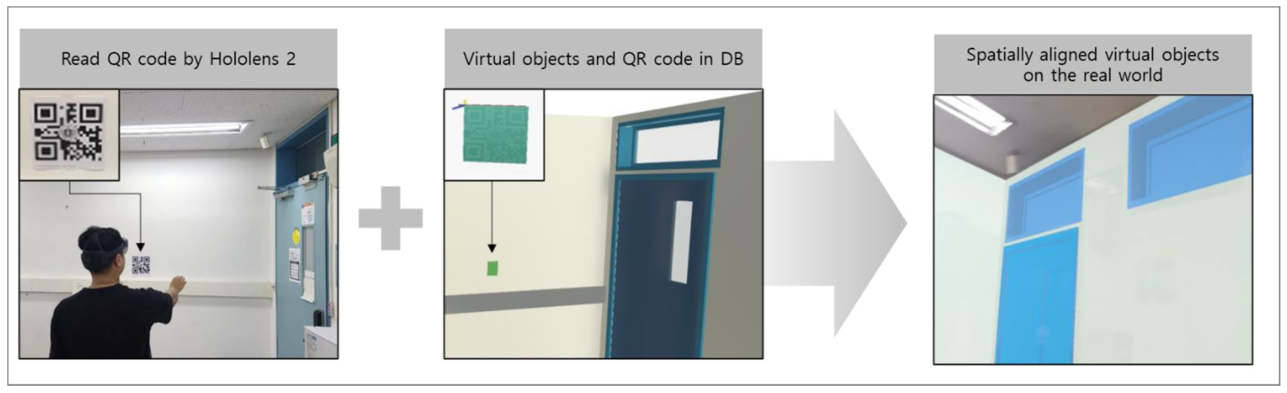
To use FOS, BIM objects first need to be superimposed into the MR environment. For this, we used the spatial alignment method using QR codes. Virtual BIM objects are spatially aligned by matching the QR code images obtained from the real world by the HMD camera and retrieved from the database in the Communication Server, as shown in
Figure 2.
FOS is designed for users to manipulate virtual BIM objects with finger-pointing cues. This function uses the right-hand model of Mixed Reality Toolkit Foundation v2.8.0 provided by Microsoft (
Figure 3a). This model identifies the ‘Grab’ gesture by tracking the thumb tip and index fingertip (
Figure 3b). The user can move the BIM object from the grab state to the desired position. The grabbed object is released and positioned there when the user gestures to release the thumb and index finger, as shown in
Figure 3c. However, when a user moves the BIM object, it is difficult to position it to the desired location. Thus, a function was created to move the virtual object along the surface to solve this problem. For example, a window on a wall moves along the wall surface.
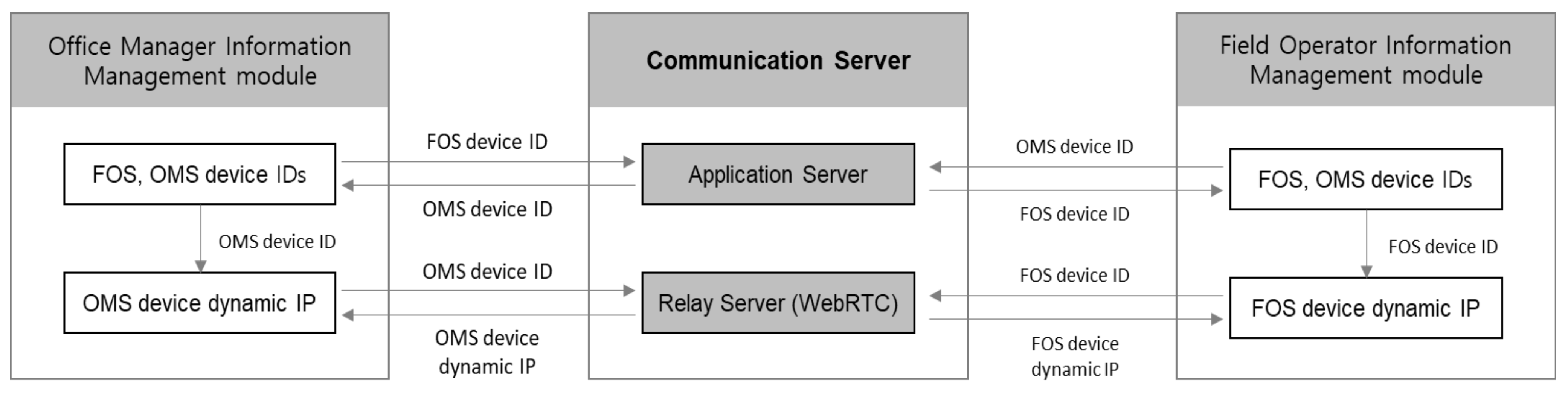
Figure 4 shows relationships between the Office Manager Information Management module, Communication Server, and Field Operator Information Management module. The Office Manager Information Management module is developed to prevent disconnection even if the IP address of the OMS device is changed. For this purpose, the Application Server and Relay Server of the Communication Server have been designed to manage FOS and OMS device IDs and the dynamic IP address of the OMS device. Usually, this communication device works only in the Wi-Fi zone; Thus, it has a spatial limitation because the IP address varies depending on the connection location. This study overcomes this limitation by applying WebRTC technology. WebRTC is a technology to find dynamic IP addresses.
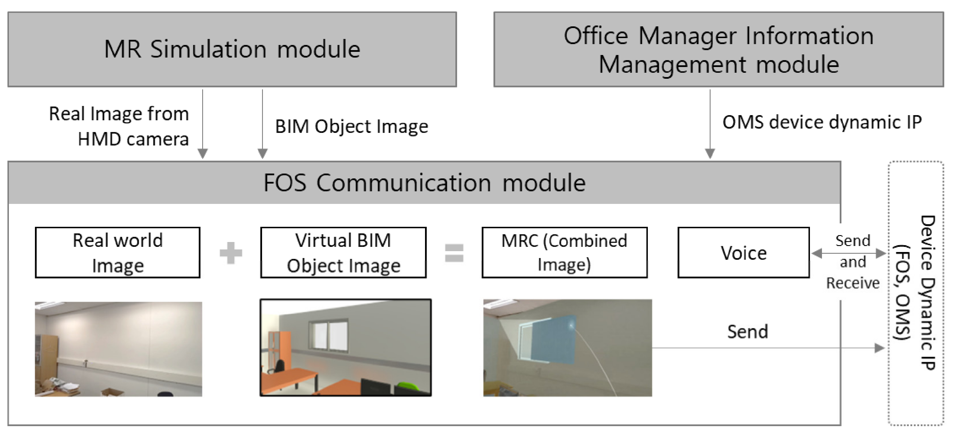
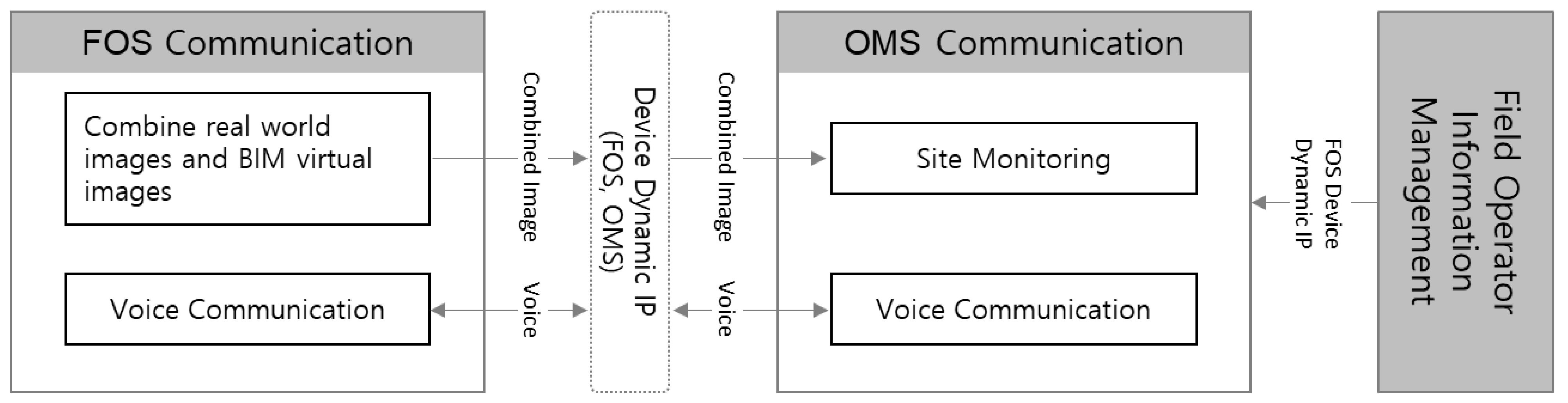
Figure 5 shows the functions of FOS modules. The FOS Communication module creates MRC, the combined image of the real-world image obtained from the HMD camera and the BIM object image retrieved from the Communication Server, and sends it to OMS. The resolution of the MRC is 960 × 540, which is transmitted in real-time at 30 FPS to OMS. Furthermore, this module assists both users of FOS and OMS in communicating by voice. Information communication with OMS is implemented through the dynamic IP addresses of OMS and FOS devices of the Office Manager Information Management module.
3.3. Communication Server
Table 3 shows the component servers and their descriptions of the Communication Server. The Communication Server consists of an Application Server and Relay Server. The Application Server manages and provides information necessary for system operation. This server stores information on BIM virtual objects, QR codes for spatial alignment, IDs of FOS and OMS devices, and provides information requested by clients through the web. The Relay server enables direct communication between FOS and OMS based on Web Real-Time Communication (WebRTC). WebRTC is a technology for communication between devices to which dynamic IP addresses are assigned. In general, mobile devices use dynamic IP addresses, and for remote collaboration, a connection must be maintained even when the IP addresses of FOS and OMS devices changes frequently. To this end, this study built a WebRTC-based Relay Server for devices that can track IP using ICE and STUN provided by Google (
stun.l.google.com:19302 (accessed on 17 May 2022)) [
23].
3.4. Office Manager System
The OMS is a web program consisting of the Field Operator Information Management module and the OMS Communication module. The Field Operator Information Management module was developed to prevent disconnection even if the FOS device IP address changes. For this purpose, the OMS was designed to manage its own ID and the ID and IP address of the FOS device through the Application Server and Relay Server of the Communication Server. The OMS runs on a desktop or tablet PC equipped with any web browser.
The OMS communication module shows the MRC video sent by the FOS Communication module in real-time on a web browser, as shown in
Figure 6. Office managers can monitor the site by watching this video. Furthermore, the manager can verbally communicate with a field operator through the OMS Communication module. Data are directly transferred between the OMS and FOS through the dynamic IP address of the FOS and the OMS devices.
4. System Usability Test
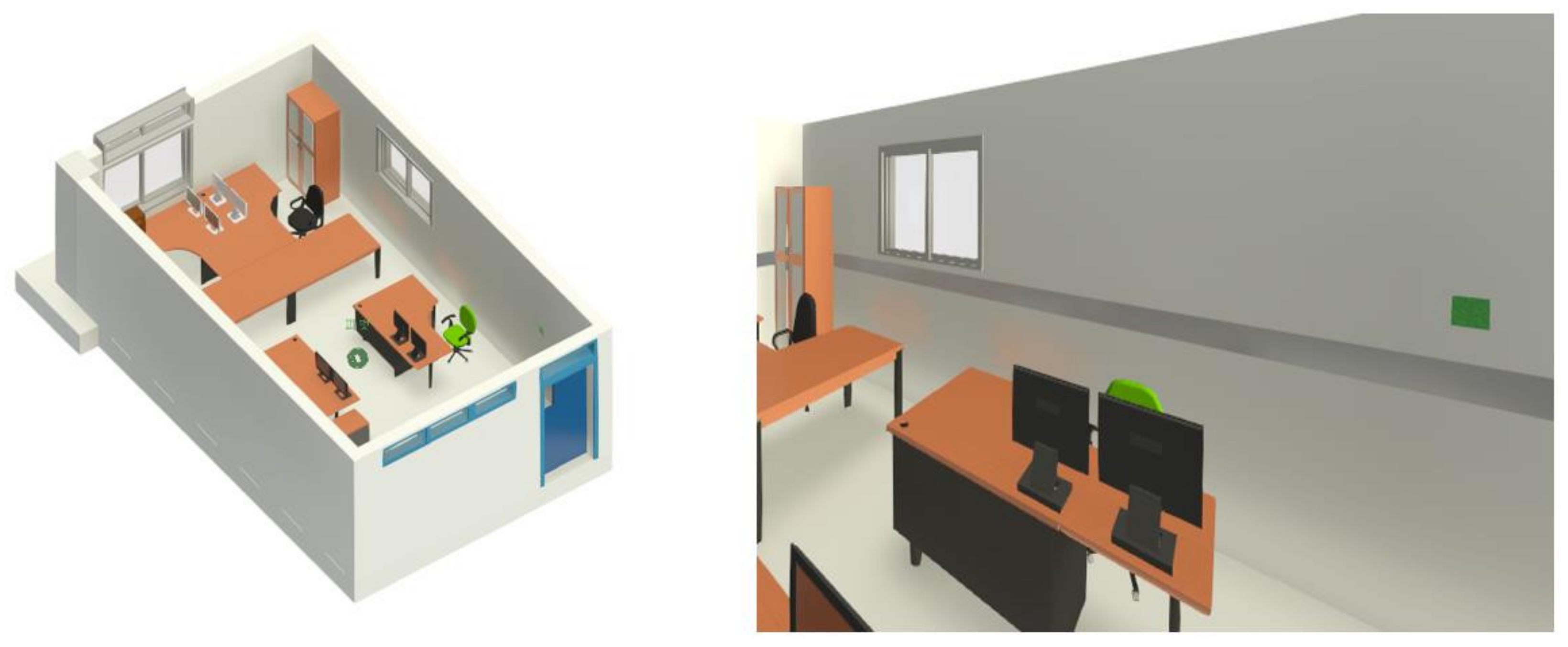
A user study was conducted to evaluate the usability of the developed system. We selected a laboratory as a test site and created BIM drawings of the laboratory, as shown in
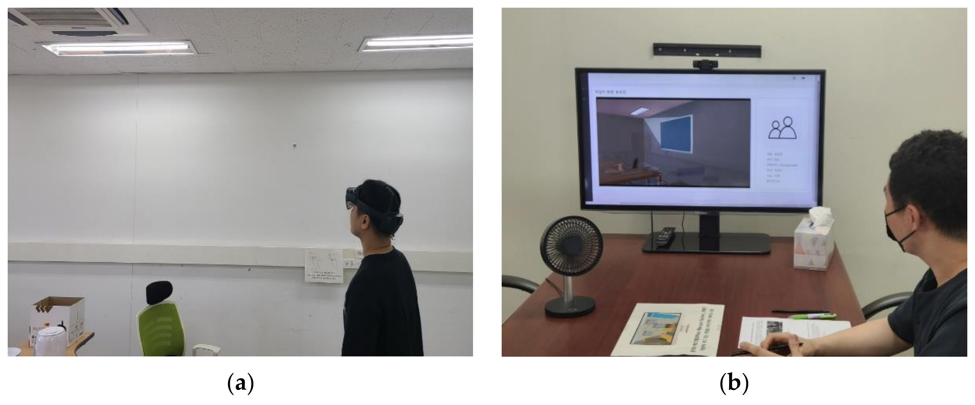
Figure 7. The test is conducted in a group of two remotely separated persons. One tester uses FOS in the laboratory (
Figure 8a), and the other uses OMS in a remote office to communicate. The OMS user can simultaneously see the FOS user’s view through a desktop PC (
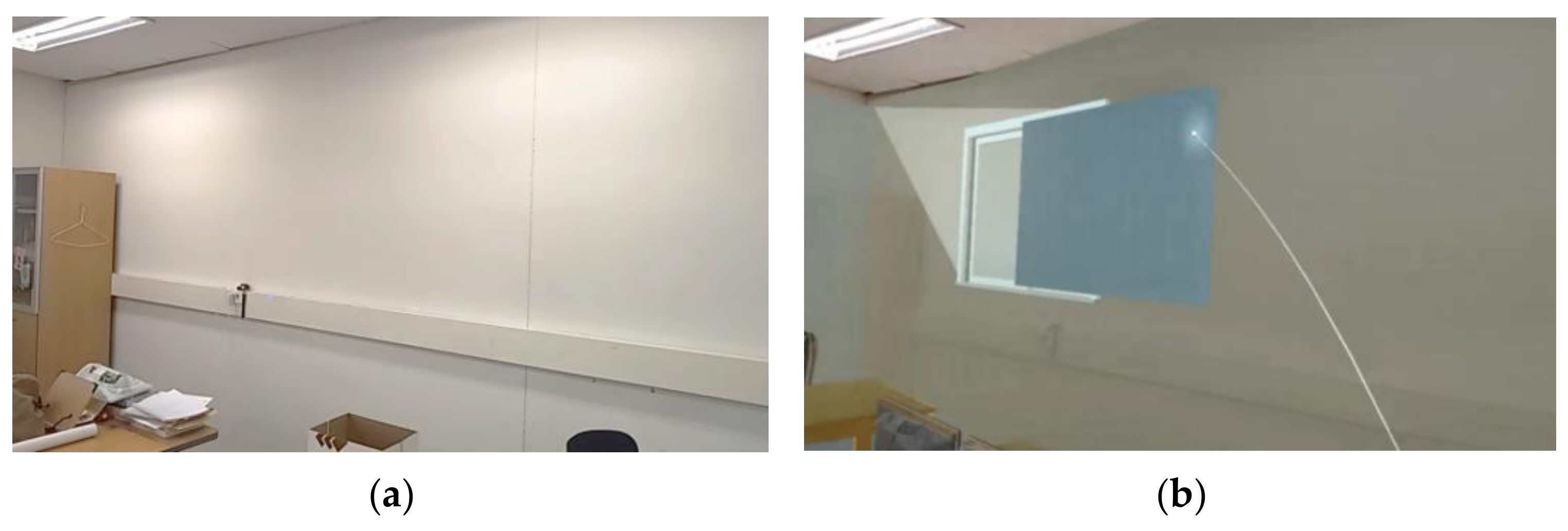
Figure 8b). The OMS user instructs the FOS user to move the virtual window object to the desired location. The FOS user wearing HoloLens 2 in the laboratory moves a virtual window object with a finger-pointing cue under the instruction of the OMS user (
Figure 9). The two can verbally communicate, sharing the same view. Through this test, we evaluated how helpful this system is for communication between a field operator and an office manager.
Ten testers participated in the experiment. They communicated using FOS and OMS to complete the mission in a pair of two. After one round of testing, they switched roles and tested again. The participants consisted of six females and four males, four undergraduate and one graduate student in the Department of Civil and Environmental Engineering, and two undergraduate and two graduate students in the Department of Architecture. Most of the students were new to MR devices.
After the test, testers responded to the following questions on a 5-point Likert scale (1: Strongly disagree, 2: Disagree, 3: Neutral, 4: Agree, 5: Strongly agree). As a result of the test, it was found that most of the participants had a positive evaluation of the developed system (
Table 4).
The FOS View helped identify the location of the virtual object.
The FOS user could move the virtual object to the desired location.
The FOS user could communicate effectively with OMS users.
The OMS user could understand the laboratory situation that the FOS user saw.
The OMS user could communicate effectively with the FOS user.
This system can be effectively used for remote collaboration at the construction site.
5. Discussion
This study contributes to remote collaboration in the AEC industry by combining the potential of BIM and MR for remote collaboration. Remote collaboration in the construction industry is not sufficiently pioneered, thus challenging. We can find the reason in the unique characteristics of the construction project. In the case of the manufacturing industry, many of the same products are manufactured in a structured environment, such as a factory; however, construction products are unique and attached to the surface of the earth. Therefore, the environment around the site, which is usually unstructured, is very important in a construction project. Therefore, communicating the unstructured field situation is important for successful remote collaboration. This study used BIM and MR to communicate the on-site situation and confirmed the applicability of the developed remote collaboration system.
As mentioned previously, remote collaboration research has not been sufficiently conducted in the AEC industry because construction products are attached to the land. Therefore, the spatial alignment of BIM elements is essential for remote collaboration in a construction project. On the other hand, spatial alignment is not very important in the manufacturing industry because manufacturing is product-oriented and not heavily influenced by the surrounding environment. This study showed that the combination of BIM and MR could resolve this issue.
As a result of the usability test of the developed system, testers’ positive responses were obtained, but some challenging comments were also received. The FOS users have pointed out low sound and image quality. Furthermore, a few testers indicated that the sharpness of the object hologram is low, and the viewing angle is narrow. However, these issues will be resolved as hardware and software develop. We found that the field of view was narrow in the feedback of OMS users. The testers think it is not easy to grasp and understand the overall situation of the field because the field of view is narrow. Furthermore, comments were received that it would be desirable for an OMS user to manipulate the virtual BIM object directly.
The proposed system can be used where remote collaboration is needed in the AEC industry. Especially it can be effectively used when the office manager monitors the construction site during the construction phase. The field operator can check whether the construction is proceeding as planned by wearing the FOS with receiving remote support from the office manager. The office manager can see the real-world image of the site and BIM objects superimposed without having to visit the site. For example, a project engineer at the site can monitor the artifacts such as steels and forms for quality control, while a senior manager or engineer can see the project engineer is viewing and giving instructions. This system also can be effectively utilized even in the design phase for a remodeling project. Since FOS users can manipulate virtual objects and share the MRC with remote office managers, it can be very helpful in decision-making.
6. Conclusions
This study developed a remote collaboration system based on MR. This system consists of three-unit systems: (1) Field Operator System, (2) Communication Server, and (3) Office Manager System. FOS was developed based on HoloLens 2 and consists of an MR Simulation module, Office Manager Information Management module, and FOS Communication module. Communication Server consists of Application Server and Relay Server and transmits and manages information between FOS and OMS. Finally, OMS for an office manager consists of a Field Operator Information Management module and an OMS Communication module. This paper confirmed the applicability of BIM and MR-based remote collaboration system.
The limitations of this study are as follows. First, in the current system, auditory and visual information is transmitted from FOS to OMS, but only auditory information can be transmitted from OMS to FOS, which limits two-way communication. Additional methods need to be developed to enable an office manager to give instructions in a way that includes visual information. As demonstrated in several studies, the effects of visual communication cues improve remote collaboration efficiency [
18,
19]. For example, if the text or annotation input by the office manager is displayed on the FOS view, the efficiency of remote collaboration will increase. Second, only FOS users can manipulate BIM virtual objects in MR2CS. OMS users only give instructions and cannot move or rotate the BIM objects. However, if OMS users can manipulate BIM objects, more effective communication will be possible. That way, remote collaborators can manipulate the same virtual object simultaneously. Lastly, a method to quantitatively evaluate the effectiveness and efficiency of the system needs to be presented. In this study, we received surveys from the testers for qualitative evaluations; however, a quantitative evaluation method should be introduced in further studies.


