Article

The Bearing Capacity of Dam Body Structure with Cemented and Weathered Materials: A Constitutive Model

1
State Key Laboratory of Simulation and Regulation of Water Cycle in River Basin, China Institute of Water Resources and Hydropower Research (IWHR), Beijing 100038, China
2
School of Civil Engineering, Tianjin University, Tianjin 300350, China
*
Author to whom correspondence should be addressed.
Appl. Sci. 2022, 12(17), 8572; https://doi.org/10.3390/app12178572
Submission received: 5 August 2022 / Revised: 22 August 2022 / Accepted: 23 August 2022 / Published: 27 August 2022

Abstract

:
The Cemented Sand, Gravel, and Rock (CSGR) dam of Xijiang is the world’s first dam to use weathered material. As mechanical tests have shown significant low-strength and nonlinear characteristics in the constitutive curve of CSGR with weathered materials, a more rigorous approach is required in calculation and analysis. Based on the project, a constitutive model of CSGR with weathered material is constructed in the research. Then, the bearing capacity of the dam is studied by using the strength-reduction method and the overload method on the basis of the constitutive model. In order to further obtain the real bearing capacity of the dam, this paper also considers the hydraulic fracturing factor and analyzes its influence at the same time. Conclusions drawn are then applied to the Xijiang project, where the effect is promising.

1. Introduction

The CSGR dam [1,2,3] is a new type of dam that has developed rapidly in recent years, but its constitutive model is still in discussion. Some scholars have established corresponding constitutive model of CSGR based on test results. In recently published articles, Jiang et al. [4] established the double yield surface constitutive model, Guo et al. [5] and Wu et al. [6] put forward the binary parallel model based on the assumption of consistent strain, Sun [7] considered the rigid elastic model of material softening after reaching the peak stress, and Yang et al. [8] proposed a new model for the dilatancy of CSGR. Though the elastic stage of the constitutive curve is important to the engineering design of CSGR dams, the above constitutive models pay only limited attention to it. The linear elastic constitutive model by Hirose [9] and Fujisawa [10] from Japan supposed the cemented sand gravel (CSG) as linear elastic material and proposed to take the elastic ultimate strength as designing strength. Despite being widely used in CSGR dam structural calculation and analysis in China, as the strength of weathered material is weaker than traditional sand, gravel, and stone material, the stress-strain test curve of it presents significant nonlinear elasticity, resulting in distortion of the material’s characteristics with the linear elastic constitutive model. Therefore, it is necessary to consider the nonlinear elasticity in the constitutive model. The six-parameter nonlinear elastic constitutive model put forward by Liu et al. [11] exhibits better suitability for the nonlinear elastic behavior of materials; however, the complication of its parameters makes it difficult to apply in engineering practice. Few constitutive models of weathered materials in dam-building have been put forward so far. Moreover, different kinds of additives, such as Laila et al. [12,13], will also have a great impact on the mechanical properties of dam materials. This research improves the Saenz constitutive relation [14] by introducing equivalent strain, so that the model would accommodate both cemented sand, gravel, and weathered materials for the Xijiang project.
Due to some special requirements for critical conditions such as floods and earthquakes, along with the characteristics of weathered material showing large dispersion, low strength, and unevenly distributed mud and water containment, the mechanical properties of CSGR with weathered material can present great diversity, which calls for the bearing capacity of dam structure to be studied to ensure the safety of the dam. At present, the methods available for measuring the bearing capacity of CSGR dam are mainly the overload method and the strength-reduction method. Regarding Shou Koubao CSGR dams, Yang [15] used a plastic damage model and bulk density overload method to analyze the bearing capacity to compare the results with the RCC gravity dam of the same height and found that the comprehensive bearing capacity of the dam structure was higher than that of the RCC gravity dam. However, he did not conclude the difference of failure modes and vertical stress on the foundation between the two dam types. Sun et al. [16] also applied the overload method and the strength-reduction method to calculate and analyze the bearing capacity of the Hei Shuihe reservoir but lacks comprehensiveness. Xiong et al. [17] claimed that the failure mode of the hard-fill dam is tensile fracture in an upstream area and dam heel. Arefian et al. [18] revealed that the strength of the CSG dam’s building material is low, but its safety under earthquake load is consistent with that of the gravity dam. Though the differences between the CSG dam, the hard-fill dam, and the CSGR dam cannot be simply dismissed, they are fundamentally similar. Based on the proposed model and relevant literature, it is important to study the dam body’s bearing capacity using the strength-reduction method and overload method.
Nowadays, hydraulic fracturing is mainly studied in high arch dams, high concrete gravity dams, and high earth-rock dams but is yet to be introduced to dams of CSGR. A more realistic bearing capacity of the dam body may be obtained when considering hydraulic fracturing. Hydraulic fracturing [19] happens when the maximum principal stress in the dam body reaches the tensile strength of the material. Since the mechanical properties of the CSGR material are weaker than those of concrete, the dam body is more susceptible to hydraulic fracturing under abnormal water pressure, thereby reducing its bearing capacity. Jin et al. [20] divided the bearing capacity of the Xiaowan Arch Dam into four limit states for evaluation but without considering the factor of hydraulic fracturing, resulting in all four safety factors being so high that the fourth state safety factor could hardly be met. While using the extended finite element method, Pan et al. [21] studied the impact of cracks on the overload coefficient in gravity dam and revealed brittleness and unreliable characteristics, and the reduction in the dam’s overload capacity of hydraulic fracturing failure. Gan et al. [22] analyzed the effects that different water pressure forms, initial elevations and depths of cracks have on the bearing capacity and stability against the sliding of gravity dams. The study of the influence of hydraulic fracturing on the bearing capacity of the dam has theoretical and practical significance for understanding the real bearing capacity of the cemented dam.

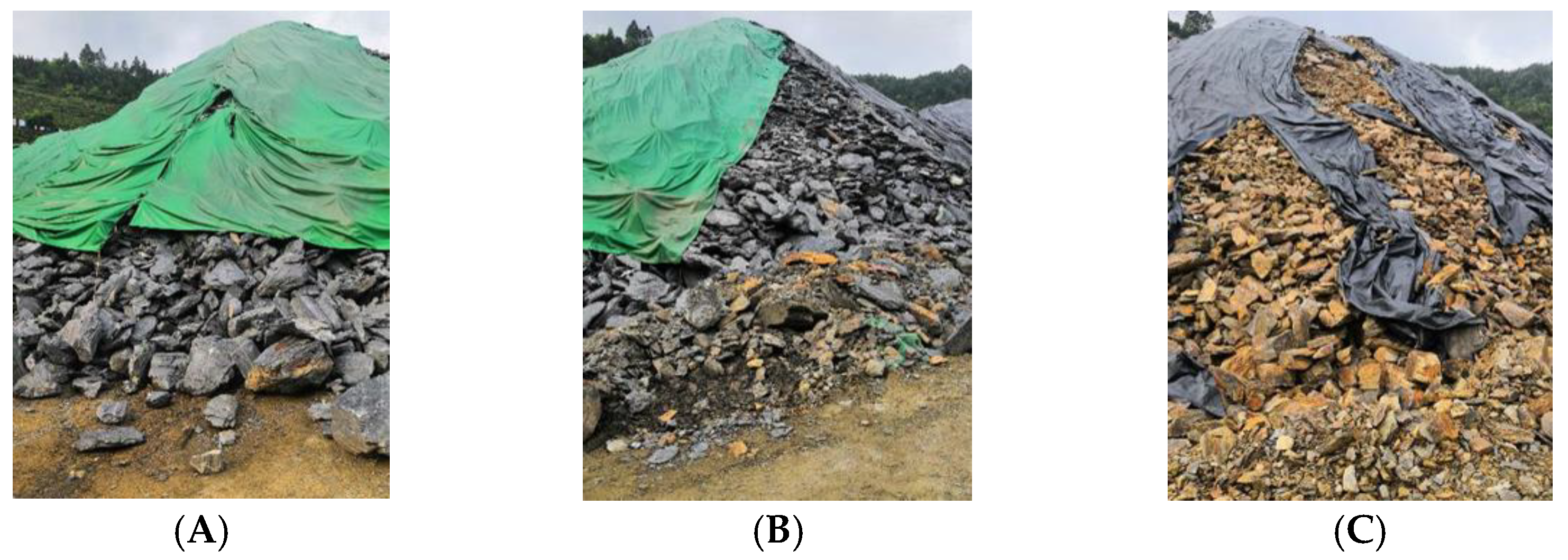
2. The Constitutive Model of Weathered Material

2.1. Improvement of Saenz’s Constitutive Model

The linear elastic constitutive [23] relationship can be expressed as
σ = λ e + 2 G ε
where σ stands for stress tensor, ε stands for strain tensor, λ and G stand for the Lame constants, and e stands for the volumetric strain with e = ε11 + ε22 + ε33.
The relationship among Lame constants, the elastic modulus, and Poisson’s ratio can be expressed as
λ = E t ν ( 1 + ν ) ( 1 2 ν )
G = E t 2 ( 1 + ν )
In the above equations, Et is the changing tangent elastic modulus, so Equation (1) can show the nonlinear change of stress and strain.
The Jacobian matrix can be obtained by taking the partial derivative of the stress tensor to the strain tensor in Equation (1), which can be expressed as
[ J ] = σ ε = [ λ + 2 G λ λ 0 0 0 λ λ + 2 G λ 0 0 0 λ λ λ + 2 G 0 0 0 0 0 0 G 0 0 0 0 0 0 G 0 0 0 0 0 0 G ]
where λ and G are both variables, the Jacobian matrix is different in each incremental step.
The strain (with 6 strain components) state of the deformed body is equivalent to one-dimensional axial strain, and the equivalent strain εe can be expressed as
ε e = 2 9 [ ( ε x ε y ) 2 + ( ε y ε z ) 2 + ( ε x ε z ) 2 + 6 ( γ x y 2 + γ x z 2 + γ y z 2 ) ]
Under the multi-directional stress state, Darwin and Pecknold [24] put forward an orthotropic stress-strain relationship matrix. They think that after offsetting the influence of Poisson’s ratio, the equivalent stress-strain relationship can still be presented with Saenz’s equation. However, it is necessary to carry out stress-strain tests in each direction, which greatly increases the test frequency and cost. Considering that no tensile stress [25] exists for CSGR dam in design conditions, the whole dam body is in elastic state under compression, which can be treated as an isotropic constitutive relation in the elastic stage calculation of the dam body to reduce test frequency and cost. The introduction of equivalent strain that can transform the complex multiaxial strain state into a simple uniaxial strain state is a computational scalar instead of the real strain of CSGR dams. By improving Saenz’s constitutive relation [14] with equivalent strain εe, the original axial strain ε is updated to the equivalent strain εe, where E0 is the initial tangent modulus, Ec is the secant modulus at the peak stress σc, and εc is the peak strain. Thus, the Saenz’s constitutive equation suitable for CSGR with weathered materials is established, which can be expressed as
σ = E 0 ε e 1 + ( E 0 E c 2 ) ε e ε c + ( ε e ε c ) 2
Differentiating (6), the tangent elastic modulus (Et) of Equation (6) can be expressed as
E t = σ ε e = E 0 ( 1 ( ε e ε c ) 2 ) [ 1 + ( E 0 E c 2 ) ε e ε c + ( ε e ε c ) 2 ] 2

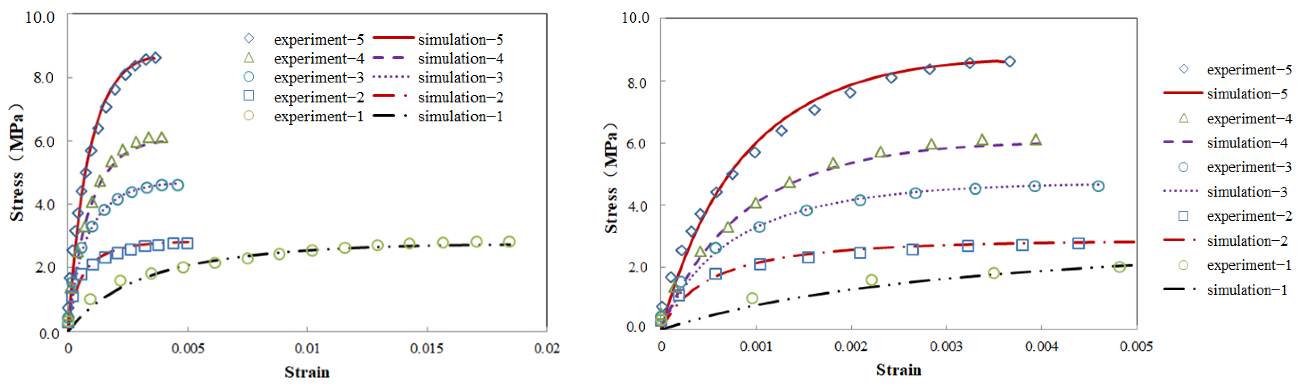
2.2. Validity Analysis of Constitutive Model

The aggregate on the construction site is classified into material A (slightly weathered material), material B (weakly weathered material), and material C (strongly weathered material) depending on the material source conditions, as shown in Figure 1. The mix proportion of material B and C with other relevant cementitious materials is shown in Table 1. Weathered gravel materials with different mechanical properties are prepared by adjusting the water-binder ratio. According to the specification [26] for testing the mechanical properties of CSGR, a standard cube specimen with a curing age of 180 days and a side length of 150 mm is built, and the compression test is carried out on the platform of the uniaxial compression testing machine to obtain the test stress-strain curves of different strength grades. The calculation parameters used in Saenz’s constitutive model can be obtained from this curve, as shown in Table 2. It can be seen from Table 3 that in the elastic stage of the test curve, the maximum proportion of linear elastic segment is 55.4%, indicating prominent nonlinear elastic characteristics, which should be focused on in the structural calculation. The maximum error between the simulation curve calculated by Saenz’s constitutive model and the test curve is 10.93%, as shown in Figure 2, which indicates that Saenz’s model can well match the elastic stage in the test curve and can be used in the structural calculation of CSGR dams.

3. Engineering Overview and Model Establishment

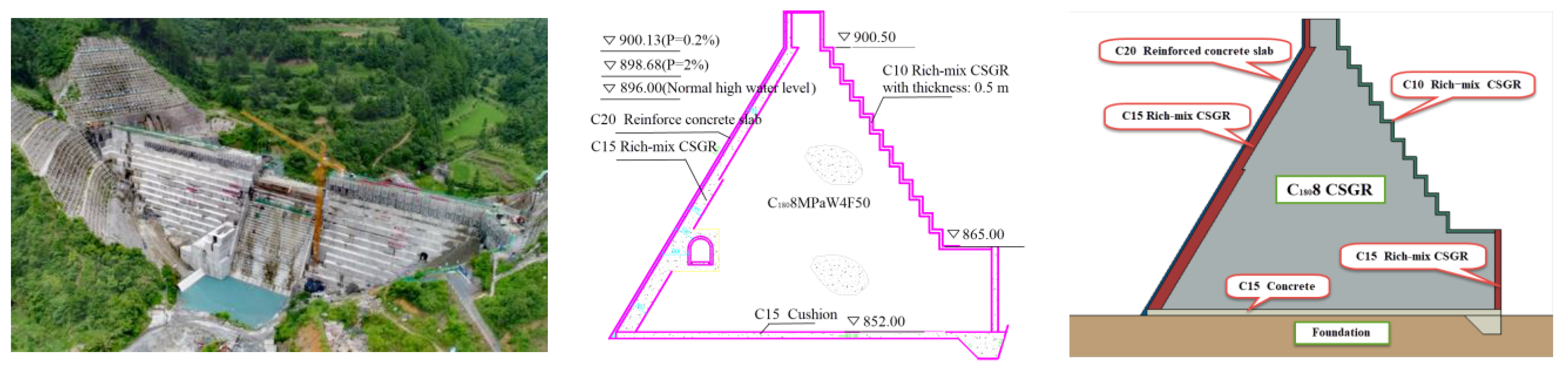
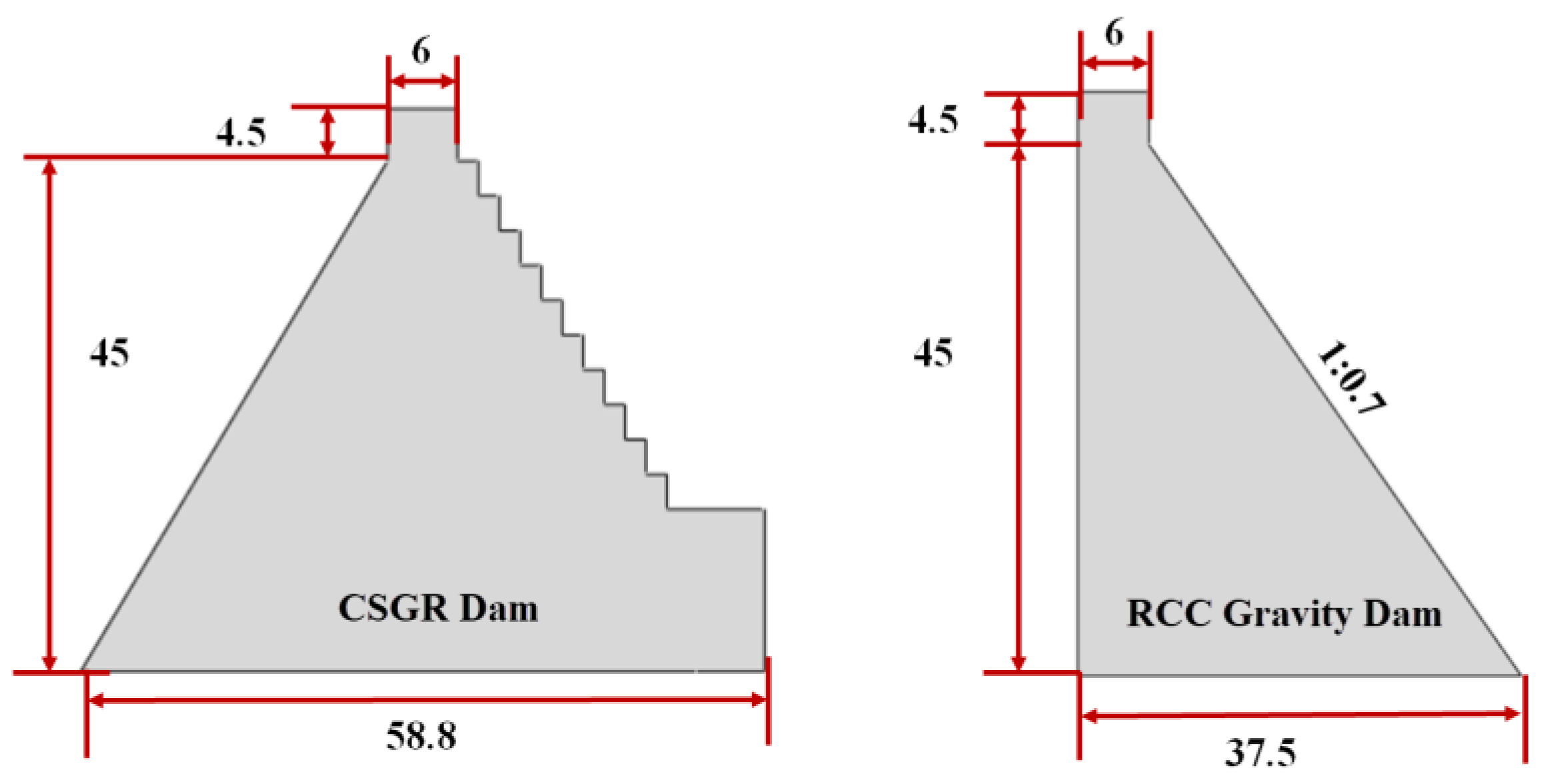
3.1. Basic Engineering Information

The CSGR dam of Xijiang in Leishan County, Guizhou is situated 1.5 km upstream from where thousands of Miao villages settle, which demands stringent safety and liability. Specifications of the dam are as follows: maximum height 49.5 m, crest width 6 m, bottom width 58.8 m, elevation of foundation 851 m, upstream slope ratio 1:0.6, average ratio of downstream stepped slope 1:0.6, and anti-seepage curtain of foundation about 3 m wide. A rich-mix CSGR of C15 and a rich-mix CSGR of C10 are, respectively, employed in upstream and downstream protection layers, the dam body adopts CSGR of C1808, with C20 reinforced concrete anti-seepage panel equipped upstream and C15 concrete cushion used in dam base, all of which can be seen in cross-section details of Figure 3. The dam features: (1) the structural separation of protection and material partition; (2) the extensive usage of local weathered materials; (3) low requirements for foundation, where construction on soft and non-rock foundation is feasible [15]; and (4) a large section size.

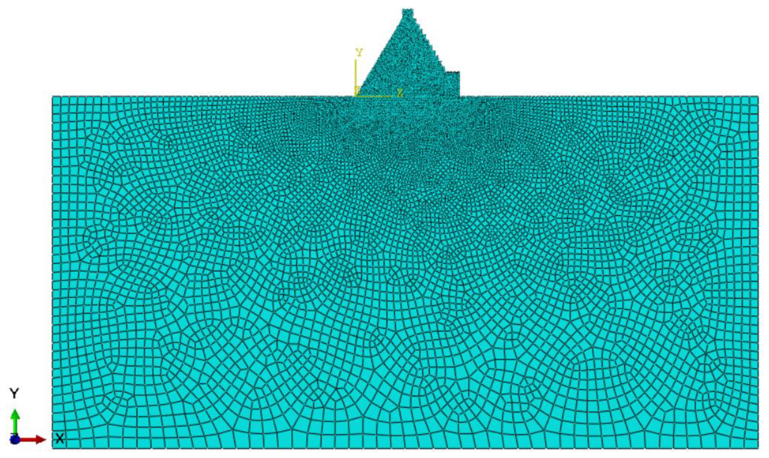
3.2. Mechanical Calculation Model and Its Parameters of Dam Structure

Based on the section geometric model and material partitions, the calculation model whose foundation is three times the size [27] of the dam model employs fully constrained displacement and left and right constrained displacement along the river in the bottom, with 11,595 quadrilateral elements and 11,419 nodes in the finite element model, as shown in Figure 4. The calculation parameters of the foundation are determined by the geological survey and design report of the Xijiang reservoir, and those of concrete material are from the specification [28] in Table 4. See Table 5 for the calculation conditions of the mechanical behavior of the dam structure.

3.3. Calculation Model and Parameters of Bearing Capacity of Dam Body

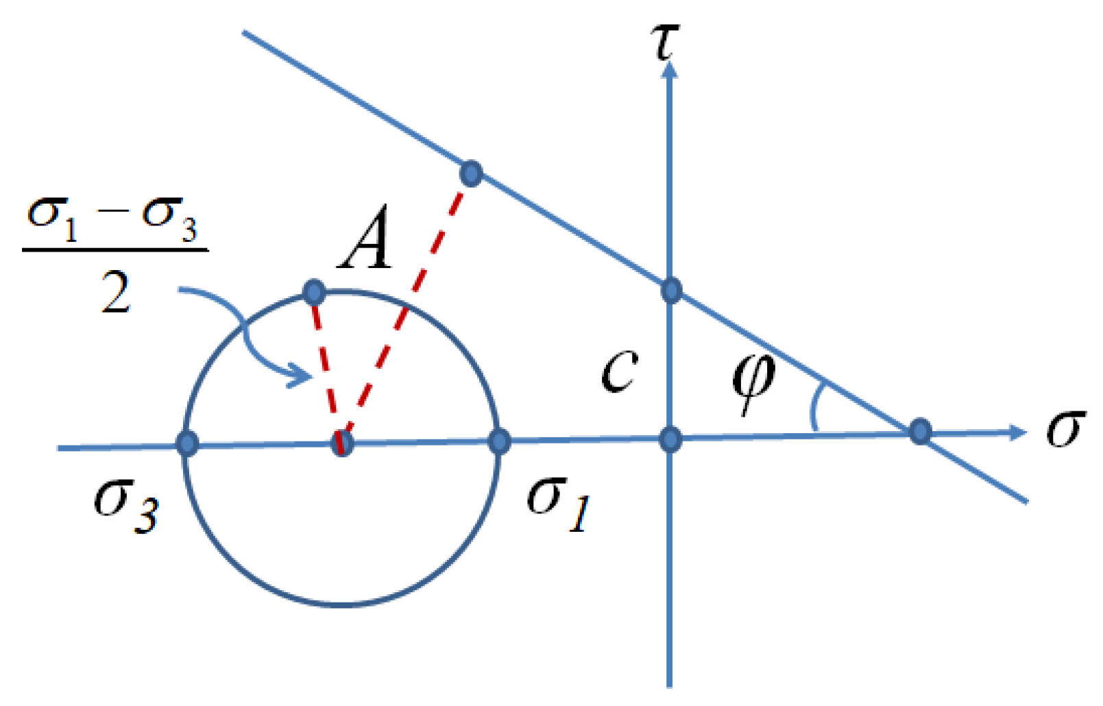
3.3.1. Yield Criteria

According to the Mohr–Coulomb yield criterion [29], the material yields when the stress state reaches the following limits:
| τ | = c σ t g φ
A = ( c t g φ σ 1 + σ 1 σ 3 2 ) sin φ > σ 1 σ 3 2
If the above Equation (9) holds, it means that the point has not yielded; otherwise, the point has yielded already, as shown in Figure 5. The strength failure limit equation can be obtained as follows:
σ 1 σ 3 = 2 c cos φ ( σ 1 + σ 3 ) sin φ
Based on Saenz’s model, the above Mohr–Coulomb yield criterion is added to calculate the bearing capacity of the dam body, namely, the strength-reduction method and the overload method.

3.3.2. Model and Parameters

The RCC gravity dam [30], which has the same height as the CSGR dam of Xijiang, is selected for comparison; the downstream slope ratio of the dam section is 1:0.7, and the upstream surface is upright. The section model information of the two types of dams is shown in Figure 6. The dam body and its foundation are consistent with those in Section 3.2. Both types of dams consider loads from the maximum water level of the upstream surface, the upstream reservoir water pressure, the maximum water level of the downstream surface, the downstream reservoir water pressure, and the weight of the dam body, and both adopt the head overload calculation method. The calculation parameters of the dam body and the foundation are shown in Table 6, among which the shear parameters of the CSGR dam (weathered material) come from the field material test [31], and those of CSGR dam (unweathered material) and RCC gravity dam are referred to in the literature [15].

3.4. Calculation Model and Its Parameters of Dam Structure with Hydraulic Fracturing

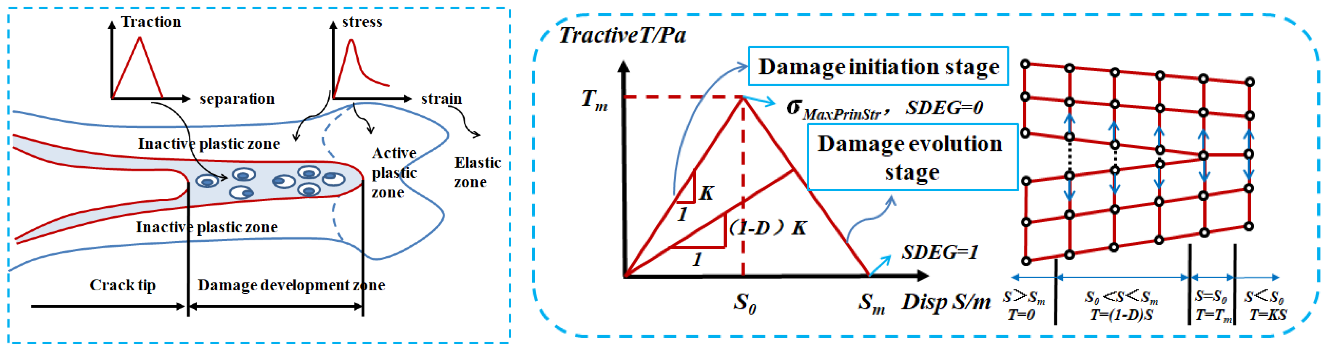
3.4.1. Failure Criterion

Crack propagation is determined based on the traction separation criterion [23] of the cohesive zone model in damage mechanics. When the crack begins to pass through the element at the crack tip after reaching the failure condition, a cohesive crack is formed. As the load increases, the stiffness of the crack tip element decreases continuously, with damage value gradually accumulating. After the damage value of the crack tip element reaches the critical value, the cohesive cracks begin to expand into the macroscopic cracks, as shown in Figure 7. The maximum principal stress criterion (Equation (11)) is selected to determine whether the damage of the element has begun, and it is considered that the compressive stress will not cause damage of the element. Weather the crack has been formed is determined with failure displacement, with the crack propagation direction orthogonal to the maximum principal stress direction. The tensile strength of the material is used as the maximum principal stress parameter of the model. The failure displacement can be calculated as the product of the plastic strain in the material stress-strain curve and the element length in the finite element. Taking the parameter mat-5 as an example, the tensile strength is 0.86 MPa, the plastic strain is 0.0026, and the element length is 1 m; as a result, the maximum principal stress is 0.86 MPa, and the failure displacement is 0.0026 m. Based on Saenz’s model, the hydraulic fracturing of the dam body is carried out by adding the traction separation criterion mentioned above.
f = { < σ max > σ max 0 } , < σ max > = { 0 , σ max < 0 σ max , σ max > 0 }

3.4.2. Model and Parameters

Having established the assumption where cracks exist only at 0, 2, 5, 7, and 9 m above the foundation on the upstream surface of the CSGR material, with the seepage effect of water in the crack dismissed, the calculation can be carried out, respectively, at crack depths of 2, 4, 6, 8, 10, and 12 m, based on the extended finite element principle using the head overload method, whose load and constraint is consistent with Section 3.2. The result can be coupled with full-head uniform pressure on the inner surface of cracks to evaluate the propagation condition. The calculation parameters of the foundation are taken from the geological survey and the design report of Xijiang reservoir, and the data in parameter mat-5 is used in CSGR, as shown in Table 7.

4. Analysis of the Results

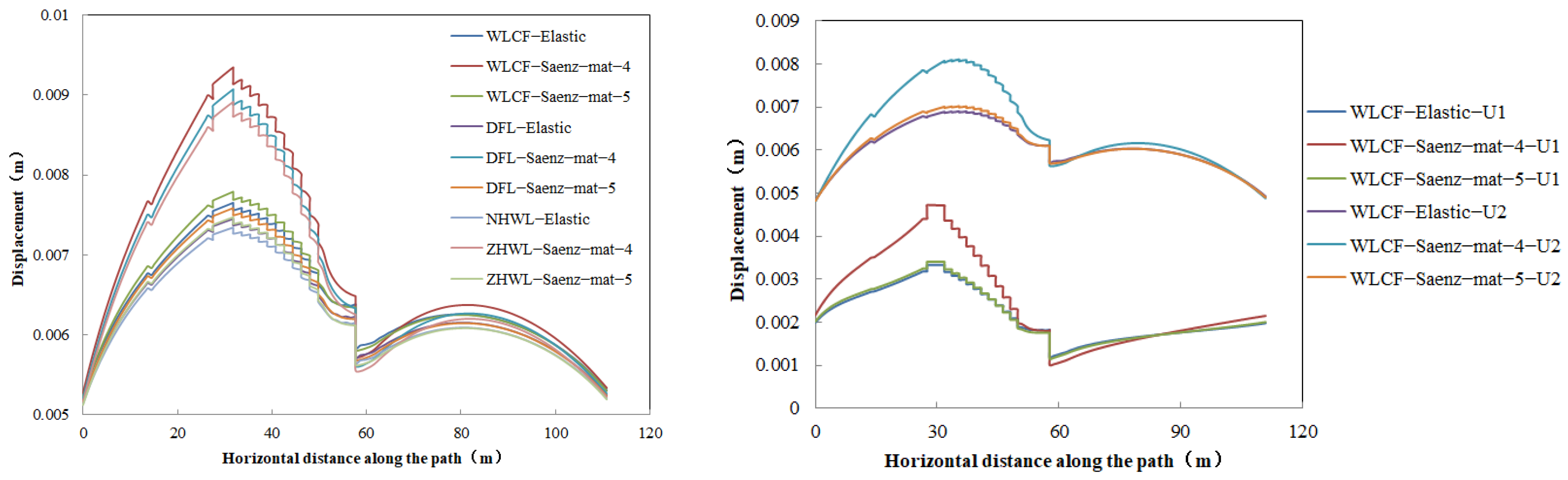
4.1. Mechanical Behavior of Dam Structure with Different Constitutive Models

The stress and displacement of the results calculated by the two constitutive models are shown in Table 8. Due to the weak stiffness and low strength of CSGR with weathered material, under the same external loads, the displacement of the dam body is considerably larger, with a maximum of 9.371 mm; the compressive stress at dam heel is smaller, with a minimum of 0.674 MPa; and the compressive stress at dam toe is larger, with a maximum of 2.328 MPa. The maximum principal tensile stress of the dam body has increased by 39.8% to 0.1595 MPa, which manages to remain within the tensile strength of C15 rich-mix CSGR, but it is still recommended to thicken the layer material or improve its tensile strength index. The minimum principal compressive stress of the dam body is almost identical, occurring in the toe area of the dam. It can be seen from Table 9 that the contour of dam displacement distribution is similar, but the contours of stress distribution are slightly different. Compared with the corresponding stress of the dam body in Table 3 of Section 2.2, this shows that mat-5 material is still in the linear elastic stage, while mat-4 has transitioned into the nonlinear elastic stage.
To further illustrate the similarities and differences between the mechanical characteristics of the dam structure of the two constitutive models, it is necessary to arrange different analysis paths within the dam body, shown in Table 10. As is seen in Figure 8, the maximum displacement variation of the upper and lower dam body close to the foundation is 2%, while that of the dam crest is 18%, which indicates that CSGR with weathered material has little impact on the foundation but a significant impact on the upper part of the dam, especially on the dam crest. This further justifies the load-bearing function of CSGR, and the thickness of C15 cushion suffices the requirements. From Figure 9, fluctuation can be noticed in the maximum principal stress of the downstream stepped structure and is intensified with weathered material, ranging 0.122 MPa~−0.523 MPa. Figure 10 shows that with the distance between the dam heel and the upstream surface being 3~13 m or 32~48 m, though the shear stress of CSGR with weathered material appears to be higher, it is still rather small in magnitude (0.042 MPa), for which the influence of weathered material of CSGR on the joint surface between the C20-reinforced concrete panel and the C15 rich-mix CSGR can be safely ignored, regarding the anti-seepage and protection function of the upstream surface. However, when the distance from the dam heel is 0~10 m, as shown in Figure 11, the shear stress of the CSGR with the weathered material increases by 54.4% to 0.185 MPa, while that of 30~42 m range is slightly larger but can be ignored, which indicates that an investigation is needed to establish the impact of CSGR with weathered material on the joint surface between C15 rich-mix CSGR and internal CSGR in construction.

4.2. Analysis on Bearing Capacity of Dam Structure

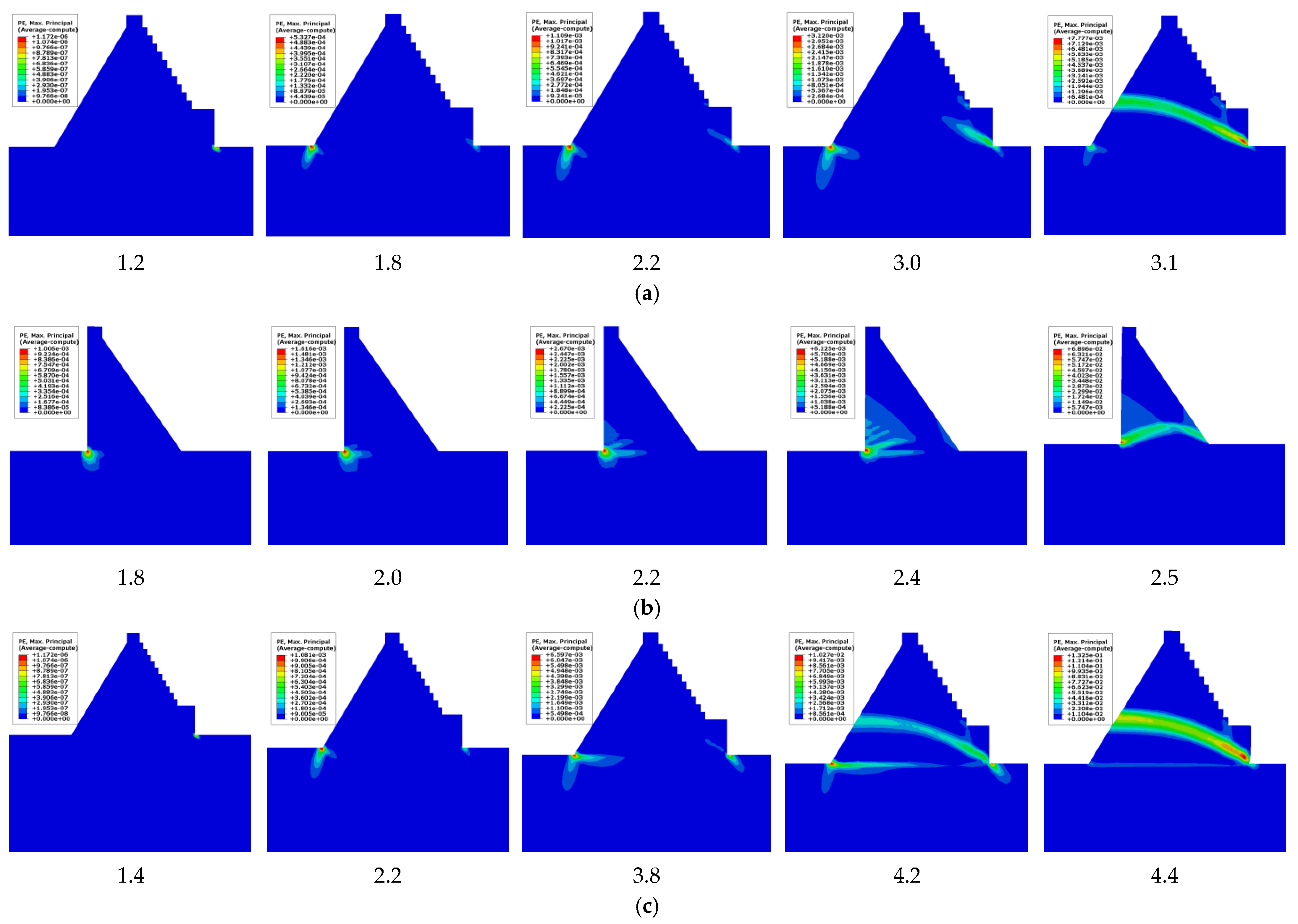
4.2.1. Calculation of Overload Capacity of Dam Body by Overload Method

The bearing capacity of the CSGR dam of Xijiang is analyzed by comparing different types of dams and the shear strength parameters of dam bodies that are of the same type. The evaluation indexes selected are the dam crest displacement along the river, the overload failure modes of the dam body, and the vertical stress on the foundation. Drawn from the displacement of the dam crest along the river in Figure 12, with the overload safety factors of the RCC gravity dam, the CSGR dam (with weathered material) and CSGR dam (without weathered material) are, respectively, 2.4, 3.1, and 4.2; the comprehensive overload capacity of the CSGR dams, either with or without the weathered material, triumphs over that of the RCC gravity dam, while the safety factor of the CSGR dam with weathered material is 26.2% smaller than that without the weathered material. The mechanism of the plastic failure mode of the CSGR dams can be seen in Figure 13, which starts with the plastic zone in the dam toe and ends with the dam heel. After expanding through both the dam toe and the heel area, at some point the plastic zone is developed into plastic failure in the dam heel, which shall spread upstream until a buckling failure is formed as a result of plastic penetrating slippage. For the CSGR dam with the weathered material, when the overload coefficient is from 1.2 to 1.8, the plastic zone appears at the dam toe first and then at the dam heel. When the overload coefficient is 2.2, the plastic zone at the dam toe begins to develop toward the upstream, and the dam body is unstable until 3.1. The entire plastic penetrating slippage line of the CSGR dams appears at a height of 13~20 m on the upstream surface or 0–3 m on the downstream surface; its plastic zone grows upstream at an angle of 13~22°. For the CSGR dam without weathered material, when the overload coefficient is from 1.4 to 2.2, the plastic zone appears at the dam toe first and then at the dam heel. When the overload coefficient is 3.8, the plastic zone at the dam toe begins to develop towards the upstream, and at the dam heel it continues to develop towards the depth of the foundation and the foundation surface. When the overload coefficient is 4.2, the sliding line of the dam body is basically formed, and the plastic zone on the foundation surface expands rapidly. Until the overload coefficient is 4.4, the dam body is unstable. The plastic failure mode of the RCC gravity dam is different from that of the CSGR dam mentioned above as the plastic zone appears in the dam heel and keeps expanding inwardly until the plastic failure is developed, which spreads downstream and eventually causes plastic penetrating slippage. When the overload coefficient is from 1.8 to 2.4, the plastic zone occurs in the dam heel area and continues to expand until the overload coefficient is 2.5, and the dam body forms a plastic through slip line and loses stability. Compared with other dam types, the overload process of CSGR has a greater impact on the foundation. The state of vertical stress on the foundation of Figure 14 shows that as the overload coefficient increases, CSGR dams have never featured the tensile stress zone, and the fluctuation of compressive stress mostly appears in dam heel. As for the RCC gravity dam, whose vertical stress on the foundation shifts violently, the tensile stress appears and keeps spreading in the dam heel when the overload coefficient reaches 1.8, and the compressive stress zone of the dam toe is continuously tightened with the growth of the stress value.

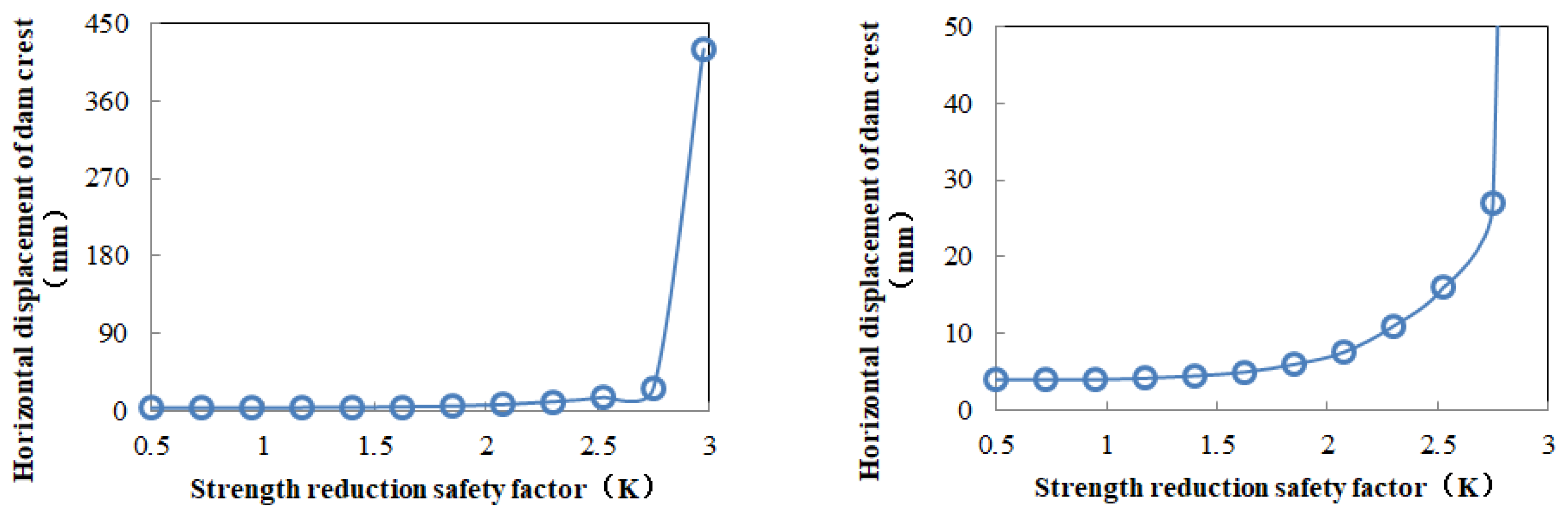
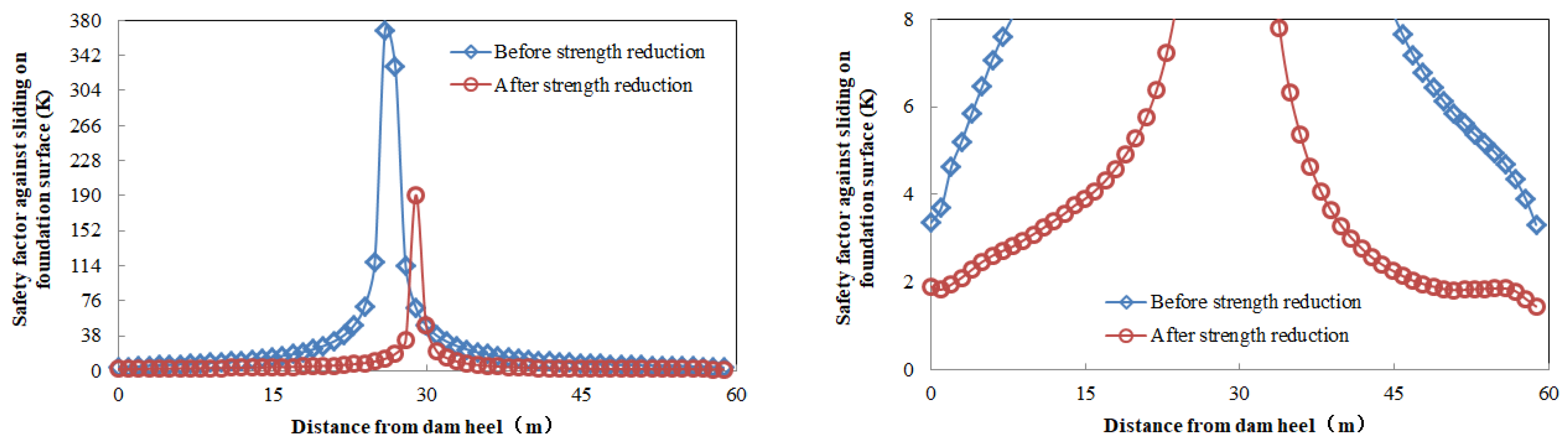
4.2.2. Calculation of Dam Body Safety Margin by Strength-Reduction Method

Considering that the strength of CSGR with weathered material is key to the scale of the dam’s bearing capacity, the strength-reduction method is adopted to analyze the safety margin of the CSGR dam (with weathered material), which requires the plastic model for the dam and the foundation, with calculation parameters shown in Table 6. The solution consists of a division of shear parameters of each group by a strength safety factor and nonlinear calculation with program non-convergence as the calculation criterion. With displacement along the river value in Figure 15, the strength reduction safety factor of the dam body, or in other words, the safety margin, can be calculated 2.75. The finite element equivalent stress method [32] and shear-break strength formula are used to calculate and analyze the stability against the sliding of each point on the dam foundation, whose results are shown in Figure 16. Being smallest in the dam heel at 3.35 and the dam toe at 3.31 but biggest in the middle, the safety coefficients of stability against the sliding figures above have been reduced by 43.3% and 56.5% to 1.9 and 1.44 with strength reduction, respectively, which justifies the great influence of the strength reduction process of the dam body on the stability against the sliding of the foundation.

4.3. Bearing Capacity of Dam Body with Hydraulic Fracturing

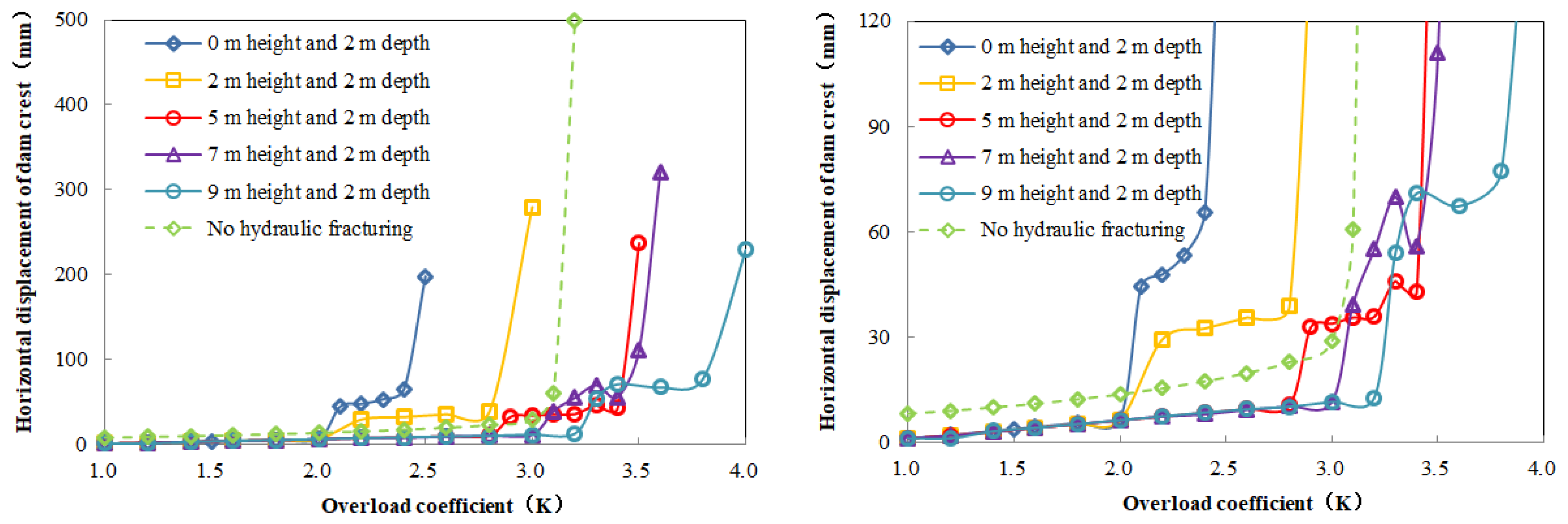
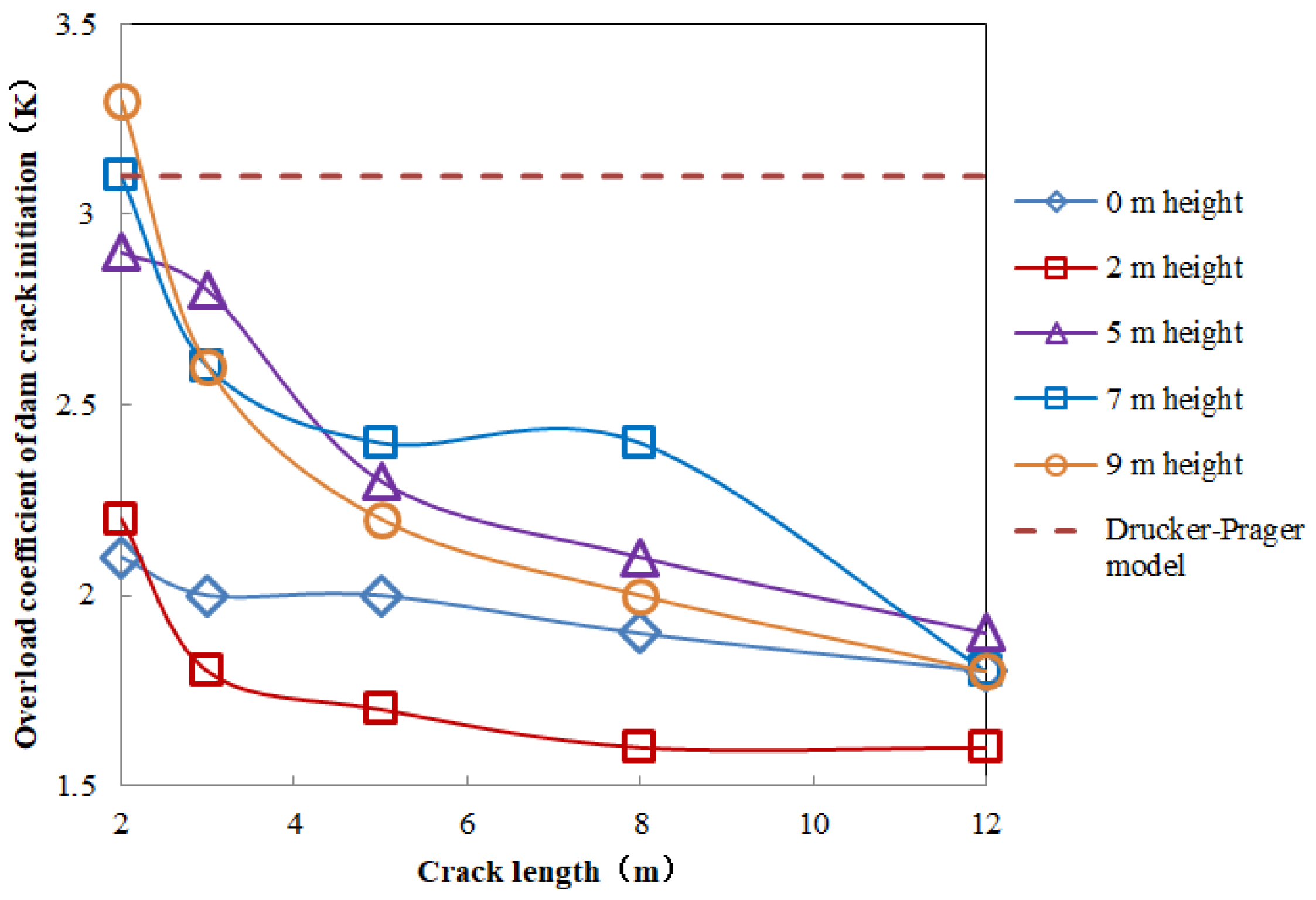
4.3.1. Overloading Capacity of Dam Body with Hydraulic Fracturing

Due to the brittleness and variability of the crack propagation [21] in the dam, the displacement curve along the river exhibits great fluctuation. At a crack depth of 2 m, the overload safety factors at heights of 0 m and 2 m from the foundation are 2.4 and 2.8, respectively, as opposed to the ones not considering hydraulic fracturing whose overload safety factors are both 3.1, as shown in Figure 17, resulting in the difference of the dam’s overload capacity of 22.6 % and 9.7 % and closer to the reality. It is more beneficial to determine the failure mode of the dam body by the overload coefficient of the crack initiation. It can be seen in Figure 18 that if the overload coefficient of crack initiation is greater than that of the plastic model in Section 3.1, plastic failure would appear superior to hydraulic fracturing failure, making the dam features a plastic failure, as shown by the cracks that are 2 m deep, 7 m deep, or 9 m deep relative to the foundation. If the overload coefficients of initiation are less than those of the plastic model in Section 3.1, this indicates that the hydraulic fracturing failure takes precedence over the plastic failure, and the dam will undergo hydraulic fracturing failure.

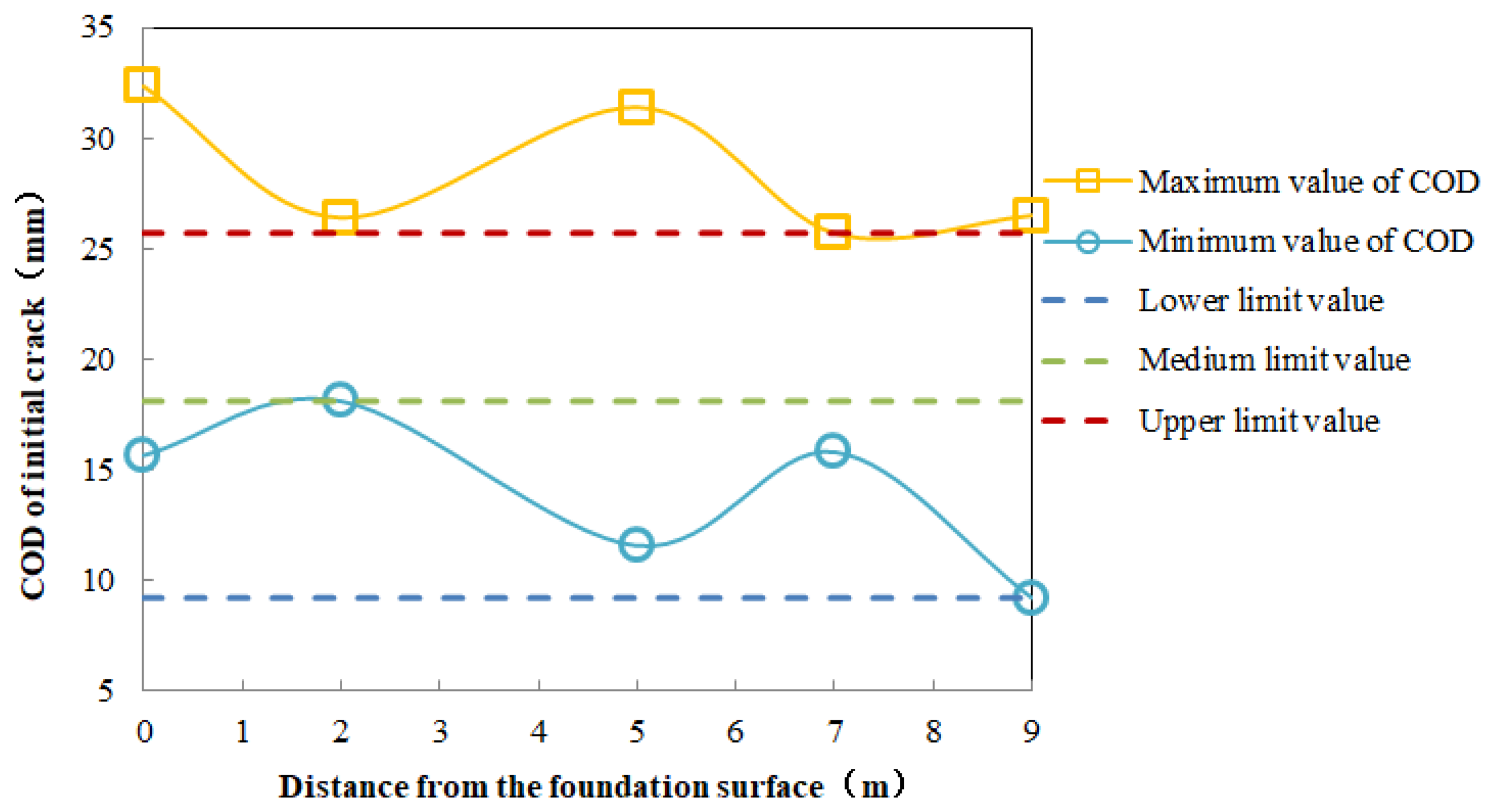
4.3.2. Suggestions on Dam Crack Propagation Treatment

The crack opening displacement (COD) is crucial to suggestions on the treatment of dam cracks. As can be seen from Figure 19, the two curves, respectively, denote the set of minimums and maximums of the COD of the dam body at different elevations. One minimum (25.7 mm) is selected from the maximum value curve as the upper limit line, one maximum (18.1 mm) is selected from the minimum value curve as the middle limit line, and one minimum (9.2 mm) is selected as the lower limit line from the minimum value curve. If the COD is less than the lower limit line (9.2 mm), the risk of crack propagation in the dam body is low, and there is no need to worry about dam damage; when the COD is between the lower limit line and the middle limit line (18.1 mm), careful observation and appropriate repair is indicated as the crack has a great risk of expansion; when the COD is between the middle limit line and the upper limit line (25.7 mm), this reveals that the risk of dam instability is increasing as a result of the continuous expansion of the cracks, with actions needed to lower the water level for reduced water pressure and to repair the cracks as soon as possible; once the COD exceeds the upper limit line, the dam body has the highest risk of instability, which urges evacuation in the downstream area.

5. Summary and Conclusions

Based on the CSGR dam of Xijiang, this research studies the constitutive model-bearing capacity of the dam body and the influence of hydraulic fracturing on structural safety and shows that the obtained bearing capacity of the dam body conforms to the actual situation. Meanwhile, the safety factor of the weathered material on the CSGR dam obtained is of theoretical and practical significance to ensure safe construction of the dam, which can be used as a reference for similar projects. The main conclusions are summarized as follows:
(1)
The improved Saenz’s model can be used as a constitutive model in the structural calculation of CSGR with weathered material, and the dam stress may enter the nonlinear elastic stage.
(2)
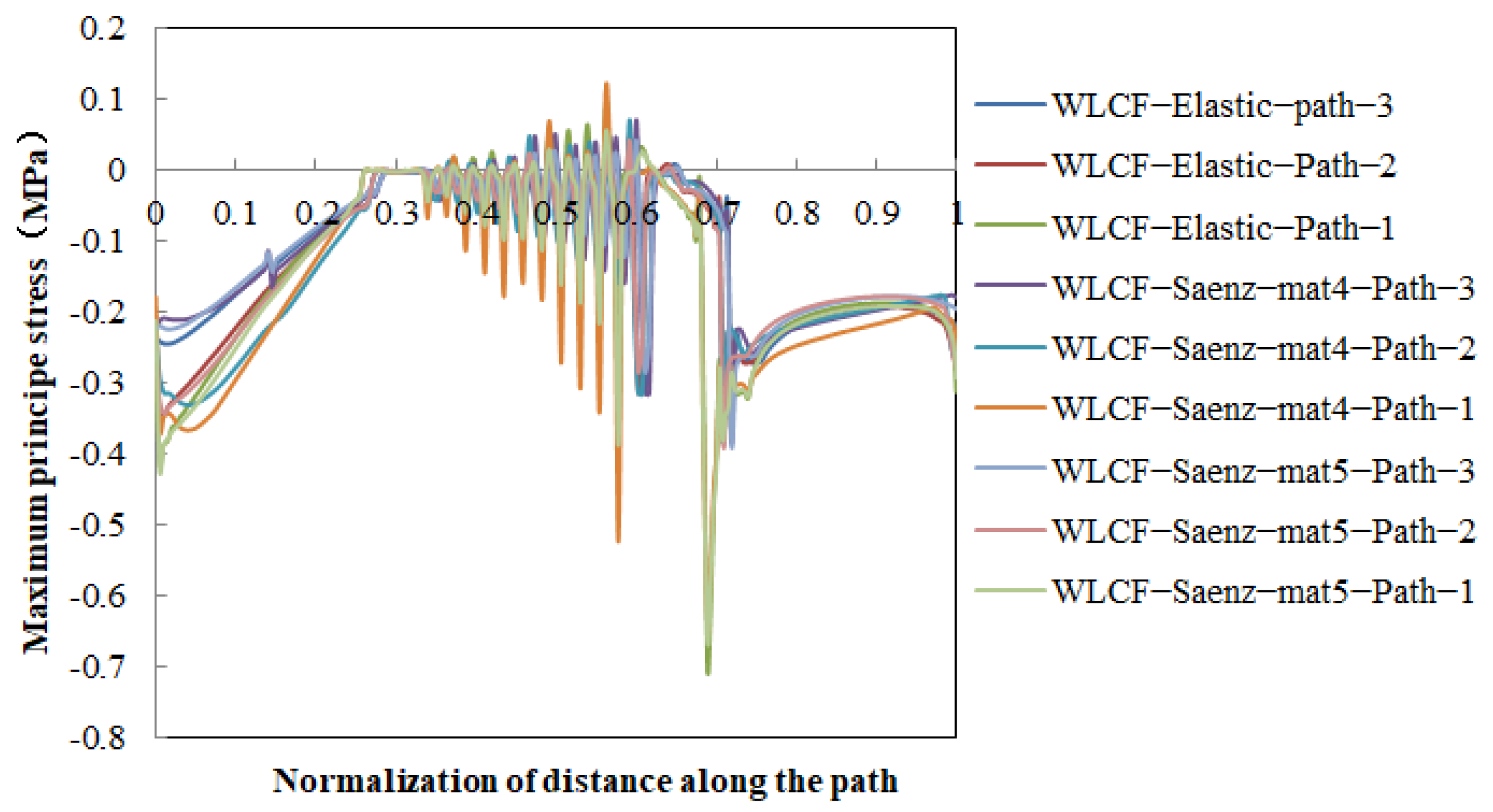
The CSGR with weathered material features larger displacement of the dam body and slightly changed distribution of the stress contour, despite increased maximum principal stress on the downstream surface and intensified fluctuation. It is recommended to increase the material strength and structural thickness of the stepped protective layer on the downstream surface.
(3)
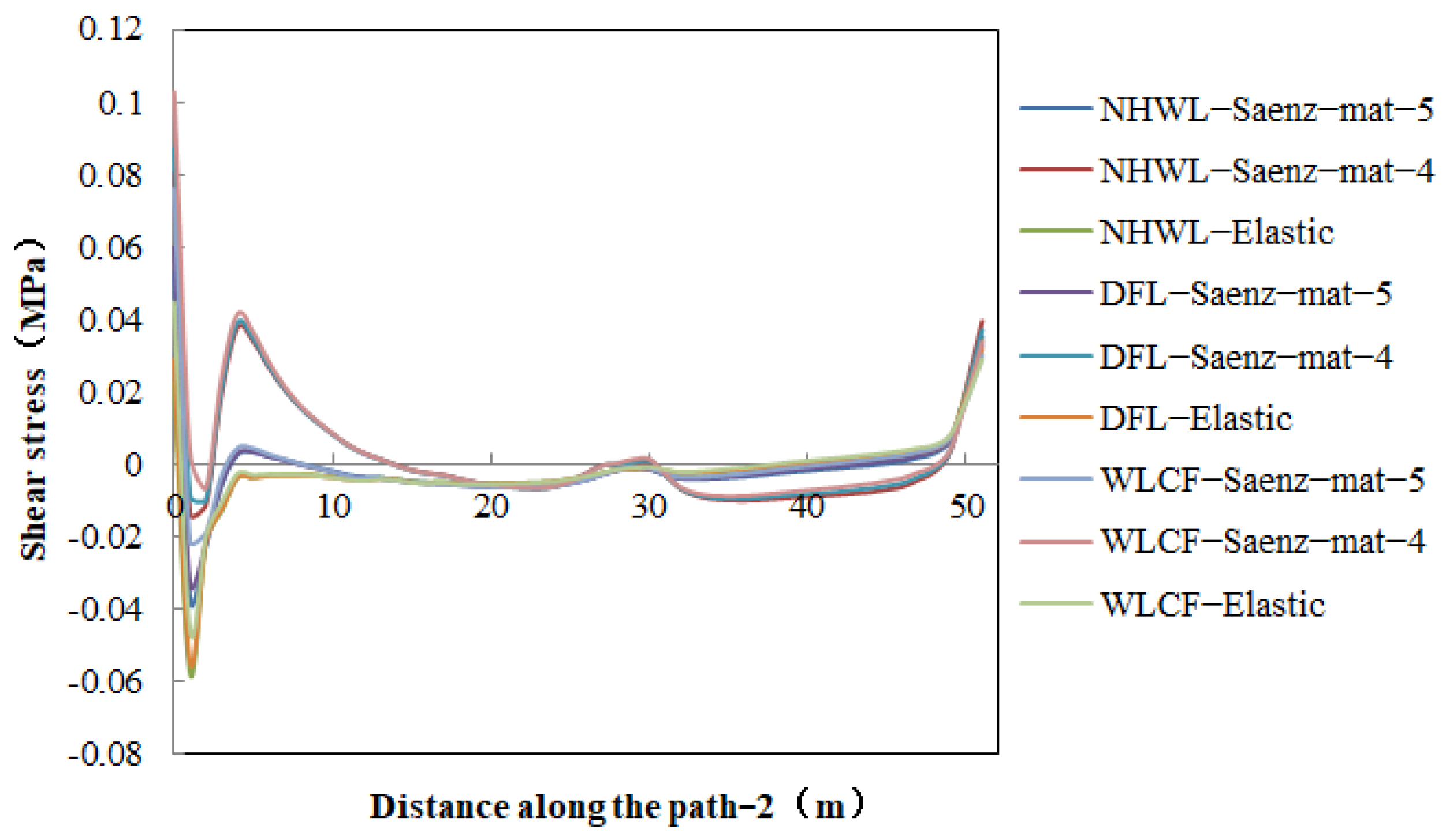
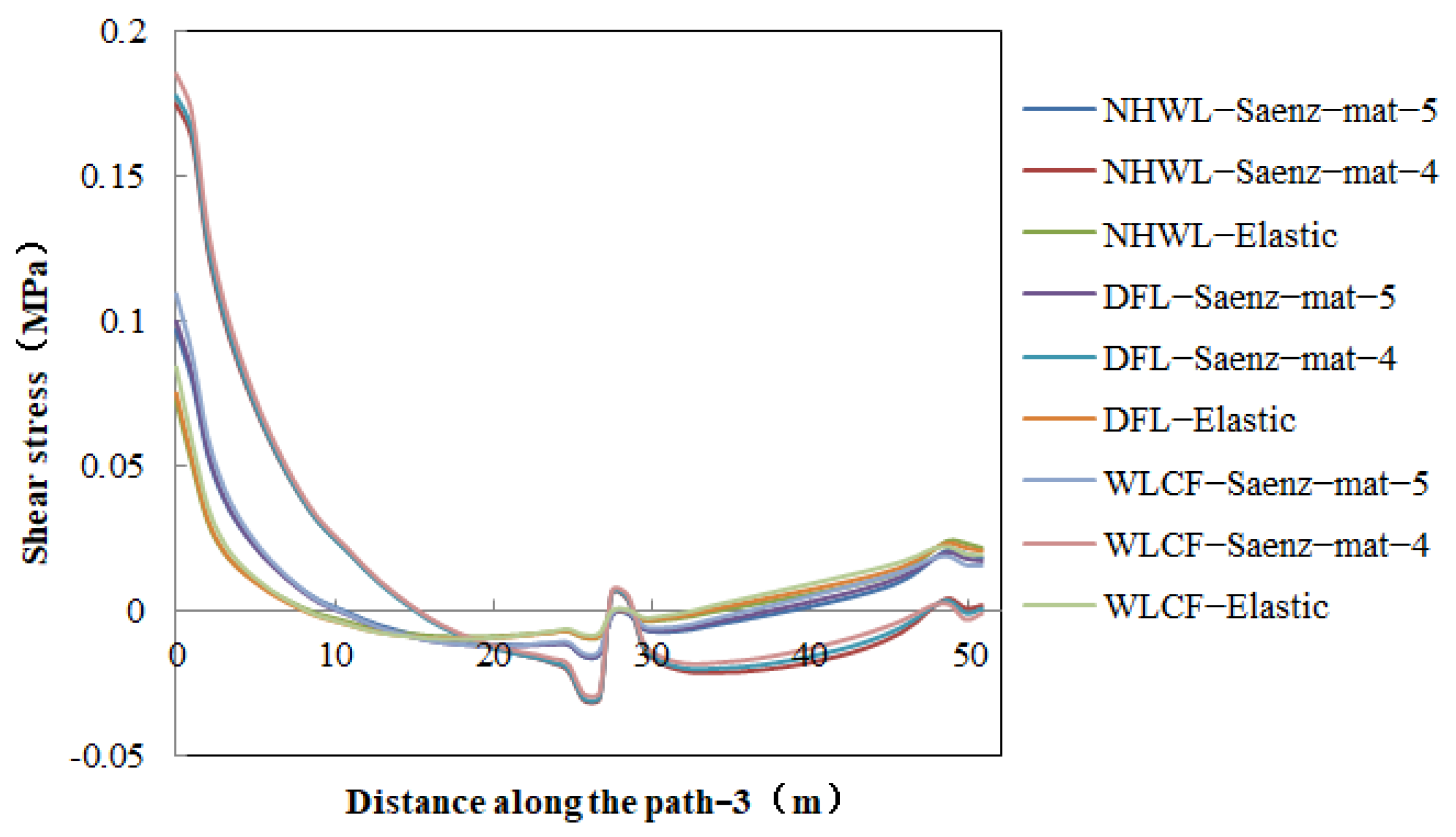
On the upstream surface, the influence of CSGR with weathered material on the seepage prevention and protection function can be ignored. However, the shear stress on the joint surface between C15 rich-mix CSGR and internal CSGR increases significantly and should be closely monitored during construction.
(4)
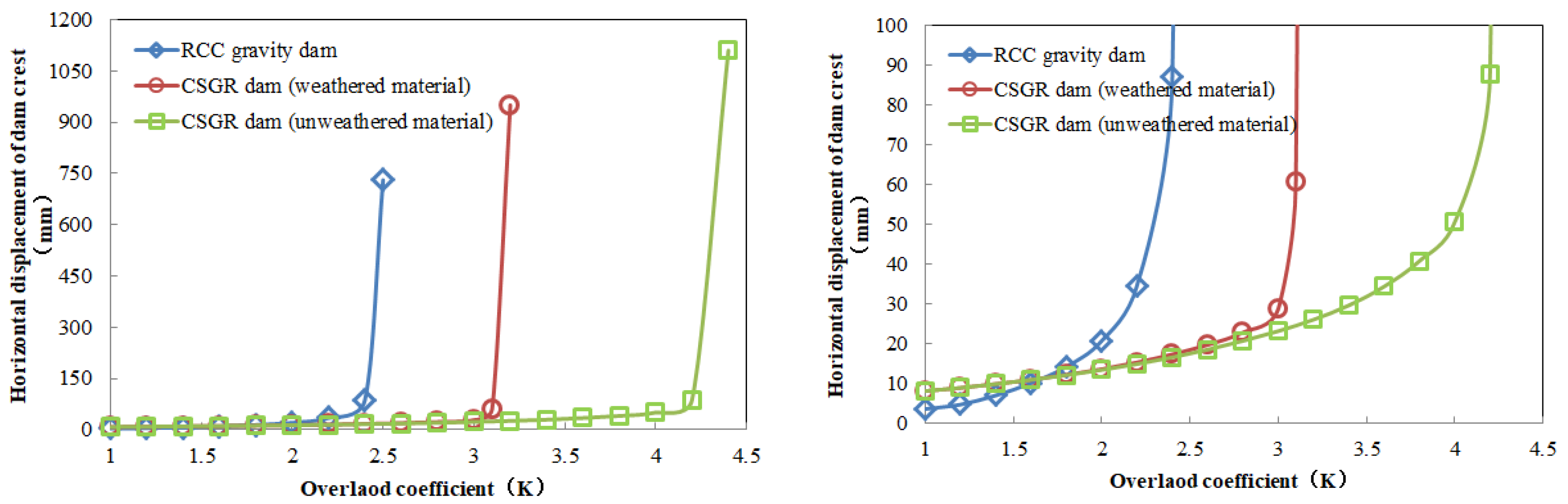
With the overload safety factor being 2.4, the comprehensive overload capacity of the CSGR dam with weathered material is stronger than that of the RCC gravity dam, while the overload safety factor of the CSGR dam without weathered material is 26.2% higher than that of CSGR dam with weathered material. The safety margin of the dam is 2.75.
(5)
According to results on the influence of cracks with different depths and heights, hydraulic fracturing will significantly undermine the safety of the dam body and ensure greater safety. Suggestions on the treatment of dam cracks are given with the COD.

Author Contributions

Conceptualization, L.Z., J.J. and C.Z.; Data curation, L.Z. and Y.W.; Formal analysis, L.Z.; Funding acquisition, J.J. and C.Z.; Investigation, L.Z., J.J. and Y.W.; Methodology, L.Z.; Project administration, J.J.; Resources, J.J. and C.Z.; Software, L.Z.; Supervision, J.J. and C.Z.; Validation, L.Z.; Visualization, L.Z., J.J. and Y.W.; Writing—original draft, L.Z.; Writing—review & editing, L.Z., J.J. and C.Z. All authors have read and agreed to the published version of the manuscript.

Funding

This research is financially supported by the National Key Research and Development Plan of China under Grant No. 2018YFC0406800.

Conflicts of Interest

The authors declare no conflict of interest.

References

  1. Jia, J.S.; Liu, N.; Zheng, C.Y.; Ma, F.L.; Du, Z.K.; Wang, Y. Studies on cemented material dams and its application. J. Hydraul. Eng. 2016, 3, 315–323. [Google Scholar]
  2. Jia, J.S.; Lino, M.; Jin, F.; Zheng, C.Y. The Cemented Material Dam: A New, Environmentally Friendly Type of Dam. Engineering 2016, 4, 490–497. [Google Scholar] [CrossRef]
  3. Jia, J.S.; Zheng, C.Y.; Wang, Y.; Feng, W.; Wang, S. Theoretical discussion and practical progress of cemented material dam construction. Sci. Sin. Tech. 2018, 10, 1049–1056. [Google Scholar] [CrossRef]
  4. Jiang, M.M.; Li, W.W.; Xiang, X.; Guo, X.W.; Cai, X. Elastoplastic constitutive model with the double-yield surface of cement-sand-gravel material. Water Resour. Hydropower Eng. 2022, 53, 73–87. [Google Scholar]
  5. Guo, L.; Li, M.R.; Guo, L.X.; Zhang, F.F.; Wang, L.Y. Study on constitutive model of cement sand and gravel material. Yangtze River 2022, 53, 165–168. [Google Scholar]
  6. Wu, M.X.; Du, B.; Yao, Y.C.; He, X.F. Triaxial tests and a new constitutive model of hardfill material. Rock Soil Mech. 2011, 32, 2241–2250. [Google Scholar]
  7. Sun, M.Q.; Yang, S.F.; Zhang, J.J. Study on constitutive model for over lean cemented material. Adv. Sci. Technol. Water Resour. 2007, 3, 35–37. [Google Scholar]
  8. Yang, A.Y.; Zuo, B.J.; Wang, W.Q.; Cao, S.Y.; Zheng, F.; Wang, L.L.; Lin, X. Study on dilatancy equation of cement-sand-gravel materials. Yellow River 2022, 44, 121–124. [Google Scholar]
  9. Hirose, T. Design Criteria for Trapezoid-Shaped CSG Dams. In Proceedings of the 69th ICOLD Annual Meeting, Dresden, Germany, 3–6 August 2001. [Google Scholar]
  10. Fujisawa, T.; Nakamura, A.; Kawasaki, H.; Hirayama, D.; Yamaguchi, Y.; Sasaki, T. Material Properties of CSG for the Seismic Design of Trapezoid-Shaped CSG dam. In Proceedings of the 13th World Conference on Earthquake Engineering, Vancouver, BC, Canada, 1–6 August 2001. [Google Scholar]
  11. Liu, J.L.; He, Y.L.; Xiong, K. Study on nonlinear elasticity constitutive model of Hardfill material. J. Hydraul. Eng. 2013, 44, 451–461. [Google Scholar]
  12. Lija, R.L.; Beulah, G.A.G.; Krishanu, R.; James, B.P.L. Effect of super absorbent polymer on microstructural and mechanical properties of concrete blends using granite pulver. Struct. Concr. 2020, 22 (Suppl. S1), 898–915. [Google Scholar]
  13. Lija, R.L.; Beulah, G.A.G.; Krishanu, R.; James, B.P.L. Influence of super absorbent polymer on mechanical, rheological, durability, and microstructural properties of self-compacting concrete using non-biodegradable granite pulver. Struct. Concr. 2020, 22 (Suppl. S1), 1093–1116. [Google Scholar]
  14. Jiang, J.J.; Liu, X.Z. Finite Element Analysis of Concrete Structures; Tsinghua University Press: Beijing, China, 2013. [Google Scholar]
  15. Yang, H.C. Structural Design Research on Cemented Sand and Gravel Dam and Engineering Application; China Institute of Water Resources and Hydropower Research: Beijing, China, 2013. [Google Scholar]
  16. Sun, M.Q.; Yue, P.Z.; Zheng, C.Y. Mechanical characteristics and overload capacity of cement-sand-gravel dam. J. N. China Univ. Water Resour. Electr. Power (Nat. Sci. Ed.) 2012, 33, 56–58. [Google Scholar]
  17. Xiong, K.; Weng, Y.H.; He, Y.L. Seismic failure modes and seismic safety of Hardfill dam. Water Sci. Eng. 2013, 2, 199–214. [Google Scholar]
  18. Arefian, A.; Noorzad, A.; Ghaemian, M.; Hosseini, A. Seismic evaluation of cemented material dams–A case study of Tobetsu dam in Japan. J. Earthq. Struct. 2016, 10, 717–733. [Google Scholar] [CrossRef]
  19. Sun, Y.P. Study on Hydraulic Fracturing Mechanism; Tsinghua University: Beijing, China, 1985. [Google Scholar]
  20. Jin, F.; Hu, W.; Zhang, C.H.; Wang, J.T. Analogical project comparative study of safety evaluation for xiaowan arch dam. Chin. J. Rock Mech. Eng. 2008, 203, 2027–2033. [Google Scholar]
  21. Pan, J.W.; Zhang, C.H.; Jin, F. Failure analysis of gravity dams with existing cracks based on extended finite element method. J. Hydroelectr. Eng. 2011, 30, 138–144. [Google Scholar]
  22. Gan, L.; Wu, J.; Ma, Z.K. Analysis of hydraulic fracturing characteristics of cracks in a high concrete gravity dam heel. Adv. Sci. Technol. Water Resour. 2020, 40, 23–27. [Google Scholar]
  23. ABAQUS 6.14 Documentation; Dassault Systèmes Simulia Corp.: Providence, RI, USA, 2014.
  24. Darwin, D.; Pecknold, A. Nonlinear biaxial stress-strain law for concrete. ASCE J. Eng. Mech. 1977, 103 (EM2), 229–241. [Google Scholar] [CrossRef]
  25. SL 678-2014; Technical Guideline for Cemented Granular Material Dams; China Water & Power Press: Beijing, China, 2014.
  26. T/CHINCOLD 002-2021; Specifications for Test Methods for Mechanical Properties of Cemented Sand Gravel and Rock; China Water & Power Press: Beijing, China, 2021.
  27. Wang, S. Quality Control and Reliability Analysis of Cemented Sand, Gravel, and Rock (CSGR) Dam; China Institute of Water Resources and Hydropower Research: Beijing, China, 2019. [Google Scholar]
  28. GB 50010-2010; Code for Design of Concrete Structures; China Architecture & Building Press: Beijing, China, 2015.
  29. Zhu, B.F. The Finite Element Method Theory and Application; China Water & Power Press: Beijing, China, 1998. [Google Scholar]
  30. SL319-2018; Design Specification for Concrete Gravity Dams; China Water & Power Press: Beijing, China, 2018.
  31. Jia, B.Z.; Jia, J.S.; Zheng, C.Y.; Li, S.G.; Ding, L.Y. Experimental study of in-situ shear of cemented sand and gravel rocks layers. J. China Inst. Water Resour. Hydropower Res. 2021, 19, 1–7. [Google Scholar]
  32. Yang, H.C.; Jia, J.S.; Zheng, C.Y. Study and application of the improved finite element equivalent stress method to analyze the strength of gravity dams. J. China Inst. Water Resour. Hydropower Res. 2013, 11, 112–116. [Google Scholar]
Figure 1. Classification of aggregate in engineering site. (A) slightly weathered material; (B) weakly weathered material; (C) strongly weathered material.
Applsci 12 08572 g001
Figure 2. Comparison between test curve and simulation curve (magnification on the right).
Applsci 12 08572 g002
Figure 3. Construction process (left), design section (middle, unit: m), and calculation model (right).
Applsci 12 08572 g003
Figure 4. Finite element model of CSGR.
Applsci 12 08572 g004
Figure 5. General view of yield criterion.
Applsci 12 08572 g005
Figure 6. Two types of dam sections (unit: m).
Applsci 12 08572 g006
Figure 7. General view of fracture criterion.
Applsci 12 08572 g007
Figure 8. Displacement curve of dam structure along path-3.
Applsci 12 08572 g008
Figure 9. Maximum principal stress curve of dam structure along different paths with water level of check flood.
Applsci 12 08572 g009
Figure 10. Shear stress curve of dam structure along path-2 within upstream surface.
Applsci 12 08572 g010
Figure 11. Shear stress curve of dam structure along path-3 within upstream surface.
Applsci 12 08572 g011
Figure 12. Displacement of two dam types.
Applsci 12 08572 g012
Figure 13. Failure modes of two dam types. (a) CSRG dam (with weathered material) in overload state. (b) RCC gravity dam in overload state. (c) CSGR dam (without weathered material) in overload state.
Applsci 12 08572 g013
Figure 14. Vertical stress on foundation of two dam types. Note: CSGR-*.*-S22 for CSGR (with weathered material), CSGR-*.*-S22-Well for CSGR (without weathered material), RCC-*.*-S22 for RCC gravity dam.
Applsci 12 08572 g014
Figure 15. Strength reduction safety factor of dam body.
Applsci 12 08572 g015
Figure 16. Safety coefficient of stability against sliding on the foundation.
Applsci 12 08572 g016
Figure 17. Dam crest displacement along the river with different crack heights (enlargement on the right).
Applsci 12 08572 g017
Figure 18. Overload coefficient of dam crack initiation with different crack lengths.
Applsci 12 08572 g018
Figure 19. COD of dam body at different crack heights.
Applsci 12 08572 g019
Table 1. List of mixing proportion of test pieces for CSGR.
NumbersProportion of Weathered
Material
CementFly AshTotal AmountsWaterSand Percentage
%
Water Reducer
%
Water-
Binder Ratio
kg/m3
mat-1B50% + C50%6060120200350.71.67
mat-2B50% + C50%6060120160350.71.33
mat-3B50% + C50%6060120140350.71.17
mat-4B50% + C50%6060120120350.71.0
mat-5B50% + C50%6060120108350.70.9
Table 2. Calculation parameters of uniaxial compression simulation.
NumbersE0 (Pa)Ec (Pa)εcνError with Test Curve
mat-1938,205,008131,327,7780.0184450.213.5%
mat-25,761,383,766496,744,182.30.005003920.24.79%
mat-36,911,107,832906,005,363.90.004602220.210.47%
mat-47,273,588,2651,361,842,1390.003948210.23.29%
mat-513,758,971,7222,126,195,5560.003676160.210.93%
Table 3. List of characteristic parameters of test curve.
NumbersLinear Elastic Limit (MPa)Elastic Limit (MPa)Peak Stress (MPa)Peak Strain
mat-10.831.972.820.018445
mat-21.071.932.750.00500392
mat-31.223.224.60.00460222
mat-41.454.276.10.00394821
mat-52.696.028.60.00367616
Table 4. List of parameters of dam structure calculation.
RegionDensity (kg/m3)E (GPa)ν
CSGR2400Saenz’s model
Linear elastic model is 15
0.2
Foundation2690100.25
C20 Concrete240025.50.2
C15 Concrete2400220.2
C15 rich-mix CSGR2400220.25
C10 rich-mix CSGR240017.50.25
Table 5. Calculation conditions of mechanical behavior of dam structure.
Calculation ConditionsContent
Normal high water level (NHWL)Dam weight + upstream water level (44 m) + downstream water level (0 m) + uplift pressure
Design flood level (DFL)Dam weight + upstream water level (45.39 m) + downstream water level (7.33 m) + uplift pressure
Water level of check flood (WLCF)Dam weight + upstream water level (47.28 m) + downstream water level (9.58 m) + uplift pressure
Table 6. List of the overload calculation parameters.
TypeRegionDensity (kg/m3)E (GPa)νFriction CoefficientCohesion (MPa)
CSGR (weathered material)Dam body2400mat-50.20.750.8
Foundation2690100.250.870.6
CSGR (unweathered material)Dam body2400mat-50.21.00.9
Foundation2690100.250.870.6
RCC gravity damDam body2400280.1671.31.2
Foundation2400200.21.00.9
Table 7. Calculation parameters of crack propagation.
TypeRegionDensity (kg/m3)E (GPa)νMaximum Principle Stress (MPa)Failure Displacement (m)
CSGRDam body2400mat-50.20.860.0026
Foundation2690100.250.70.0023
Table 8. Results of stress and displacement of dam structure under various working conditions.
Calculation ConditionsConstitutive ModelDisplacement (mm)Dam Heel Stress (MPa)Dam Toe Stress (MPa)Maximum Principal Stress (MPa)PositionMinimum Principal Stress (MPa)Position
Normal high water levelElastic7.352−0.852−1.720.089C10 rich-mix CSGR for the first step downstream−2.376C15 rich-mix CSGR at dam toe
Saenz-mat-57.482−0.802−1.9210.0564−2.285
Saenz-mat-48.937−0.716−2.2140.1442−2.304
Design flood levelElastic7.462−0.849−1.7710.0919−2.4
Saenz-mat-57.596−0.798−1.9730.054−2.306
Saenz-mat-49.205−0.704−2.2580.1517−2.343
Water level of check floodElastic7.663−0.828−1.8310.096−2.472
Saenz-mat-57.803−0.777−2.0370.0569−2.374
Saenz-mat-49.371−0.674−2.3280.1595−2.413
− for compressive stress.
Table 9. Contour of stress and displacement of dam structure with normal high water level.
Constitutive ModelDisplacement ContourVertical Stress ContourMaximum Principal Stress ContourMinimum Principal Stress Contour
Elastic Applsci 12 08572 i001 Applsci 12 08572 i002 Applsci 12 08572 i003 Applsci 12 08572 i004
Saenz-mat-5 Applsci 12 08572 i005 Applsci 12 08572 i006 Applsci 12 08572 i007 Applsci 12 08572 i008
Saenz-mat-4 Applsci 12 08572 i009 Applsci 12 08572 i010 Applsci 12 08572 i011 Applsci 12 08572 i012
Table 10. List of analysis paths within dam structure.
NumbersContent
Path-1Outside upstream + dam crest + outside downstream + outside cushion
Path-2Joint surface between C20 reinforced concrete panel and C15 rich-mix CSGR + dam crest+ joint surface between C10 rich-mix CSGR and internal CSGR + joint surface between cushion and internal CSGR
Path-3Joint surface between C15 rich-mix CSGR and internal CSGR + dam crest + joint surface between C10 rich-mix CSGR and internal CSGR + joint surface between cushion and internal CSGR
Publisher’s Note: MDPI stays neutral with regard to jurisdictional claims in published maps and institutional affiliations.

