Article

Visual Servo Control of the Macro/Micro Manipulator with Base Vibration Suppression and Backlash Compensation

State Key Laboratory of Robotics and System, Harbin Institute of Technology, Harbin 150001, China
*
Author to whom correspondence should be addressed.
Appl. Sci. 2022, 12(16), 8386; https://doi.org/10.3390/app12168386
Submission received: 26 June 2022 / Revised: 12 August 2022 / Accepted: 19 August 2022 / Published: 22 August 2022

Abstract

:
This study investigates the visual servo control of the space station macro/micro manipulator system. The proposed approach is based on the position-based eye-in-hand visual servo (PBVS) and takes advantage of the hardware sensors to overcome the macro manipulator’s base flexibility and joint backlash. First, a vibration suppression approach based on the reaction force feedback control is proposed, the deflection forces are measured by the six-axis force/torque sensor at the base of the micro-manipulator, and damping is injected into the flexible base in the closed-loop control to suppress the base vibration. Second, the small changes of joint backlash are compensated based on the macro manipulator joint angles sensor and converted to the desired motion of the payloads. Finally, PBVS with the lag correction is proposed, which is adequate for the precise positioning of large payloads with significant low-frequency oscillations. Ground micro-gravity experiment implementation is discussed, simulations and experiments are carried out based on the equivalent 3-DOF flexible base manipulator system and the macro/micro manipulator ground facilities, and results demonstrate the effectiveness of the proposed control algorithm.

1. Introduction

Manipulator is the most widely used automation equipment in the robot and has been widely applied to industrial production, surgical operation, humanoid robot, underwater search and rescue, and space stations. The space station manipulators perform a number of tasks on orbit, including cargo handling, equipment installation and maintenance, space vehicle rendezvous and assisted docking, and support for astronauts in extravehicular activities (EVA) [1].
The China Space Station will be built gradually, the core module arm (CMM, 10 m length) and experimental module arm (EMM, 5 m length) are currently in orbital service [2]. For some working conditions, the manipulator not only requires an extensive range of motion but also needs to ensure the accuracy of the local operation, a relative rigid robot (EMM) mounted serially on the tip of a long, flexible robot (CMM) is often used to increase reach capability, shown in Figure 1. It is a well-known macro/micro manipulator system (MMMS), which is a kind of flexible base manipulator system (FBMS), and is often used to perform tasks that are dangerous or may be incapable for astronauts [3]. Similar applications were in the International Space Station (ISS), such as the SSRMS-SPDM provided by CSA and JEMRMS provided by JAEA [4,5].
Flexibility and backlash are two crucial factors concerning the performance of FBMS. The large scale of CMM makes the manipulator flexible, and the planetary gear reducer of CMM causes backlash and extra flexibility [6]. The dynamic coupling between the manipulator and flexible base complicates the control problem. The reaction forces and moments caused by the motion of EMM will excite the joints sliding within the backlash, thus leading to offsets at the end-effector EEF. As deflection forces increase, the flexible modes excite vibration, leading to EEF tracking errors and performance deterioration.
The tip position sensing cannot be obtained from the forward kinematics due to the imperceptible nature of flexural link displacements. One feasible solution to improve the positioning accuracy is the usage of a camera mounted at the EEF of the manipulator, which is a kind of eye-in-hand (end-point closed loop) servo system [7]. Visual servo (VS) is classified into a position-based visual servo (PBVS) and image-based visual servo (IBVS) [8]. In IBVS, the visual information is direct feedback for control to minimize the image plane error by extracting image features; in PBVS, the relative pos between the end-effector and the target is estimated, which can be controlled in the unified architecture in Cartesian space. PBVS is designed in our system, and markers are configured on the grapple fixtures outside the space station [9], the obtained full pose information (6D) helps to assist the maneuvring of the operators.
The basic PBVS control structures have been discussed by Wilson in [10,11]. For better load capacities and high precision of the EEF, the flexible states sensing and vibration control are introduced, making the control law much more complex. Various strategies have been developed to cope with a flexible base. The trajectory planning based on the input shaping [12,13] is feedforward control, which is insufficient for the system with an initial excitation. To overcome this problem, the feedback controller combined with input shaping is proposed by Cannon in [14]. However, it depends on the joint space tracking and is not suitable for eye-in-hand VS. The passive analysis with large payload [15,16] has been addressed and PD+ control is applied with the desired rigid system feedforward and tracking errors feedback. Similar PID control with a feedforward term is applied in the precise positioning of payloads by flexible space robot systems [17], however, it is an eye-to-hand IBVS.
Most commonly, the vibration damping term introduced by the micro manipulator is a feedback. Wayne J. Book studied many different ways to damp the vibration, such as active damping control in [18] and inertial vibration damping control in [19], which is usually combined with the two-time scale control in [20]. It is assumed that the tracking control and base vibrations are separated in the frequency domain, and the dynamic model is decoupled into two-time scale based on the singular perturbation theory. This concept has been widely applied in the IBVS control [21,22,23,24,25,26], where the slow control torque vanishes the image feature error and fast control torque sufficiently dampen the vibrations of the elastic mechanical structure. However, the tracking errors affected by the base vibration damping and the controller may become deficient due to modeling errors.
The base vibrations should be suppressed during the visual servo task of EEF; it is a kind of dual-task control. Torres et al. [27] firstly propose the pseudo-passive energy dissipation, the idea is to choose the PD gains in the joint controllers to transfer the energy from base to manipulator actuators. For the redundant manipulator, the reaction null-space control framework proposed by Nenchev et al. in [28] is based on the coupling momentum. In an alternative way, the resolved solution based on the null-space of the redundant manipulator is studied by the author in [29], the damping term is added in the closed-loop by the successive null space projection. Recently, augmented projections based on coordinate transformation is proposed by Dongjun Lee in [30]. Different coordinate transformation methods are proposed by Gianluca Garofalo et al. in [31,32], where the dynamic consistency is satisfied with the decoupling of joint space and operation space.
The macro/micro manipulator is difficult to model. The joint of the EMM is flexible with backlash, and the joint stiffness in and out of the backlash differ. The dynamic model-based control, as mentioned before, is inadequate for this situation. However, the sensors of the manipulators will make it possible for precise deformation measurement. The six-axis force/torque sensor (FTS) is designed in [33], which can measure the three orthogonal forces and torques between EMM and CMM. The base force/torque sensing are discussed for different applications [34,35,36], but with a lack of macro/micro manipulator vibration suppression control.
The contribution of this paper is to deal with the vibration problem of the MMMS with PBVS, the requirements of the control strategy are related to the robot’s high speed and high precision operations with large payload. Firstly, the PBVS is performed effectively in cooperation with eye-in-hand camera and other types of sensors due to the multi-sensor data fusion. Secondly, the vibration control of the FBMS is studied by the FTS damping control and backlash compensation.
This paper is organized as follows. Section 2 discusses the measurement of the manipulator payload motion. In Section 3, an implementation of a visual servo is given, including base vibration and backlash compensation. In Section 4, simulation results are discussed for the macro-micro manipulator systems. In Section 5, experimental implementation and evaluation of a laboratory’s flexible base manipulator system is discussed. The paper ends with concluding remarks in Section 6.

2. Vision-Based Measurement System

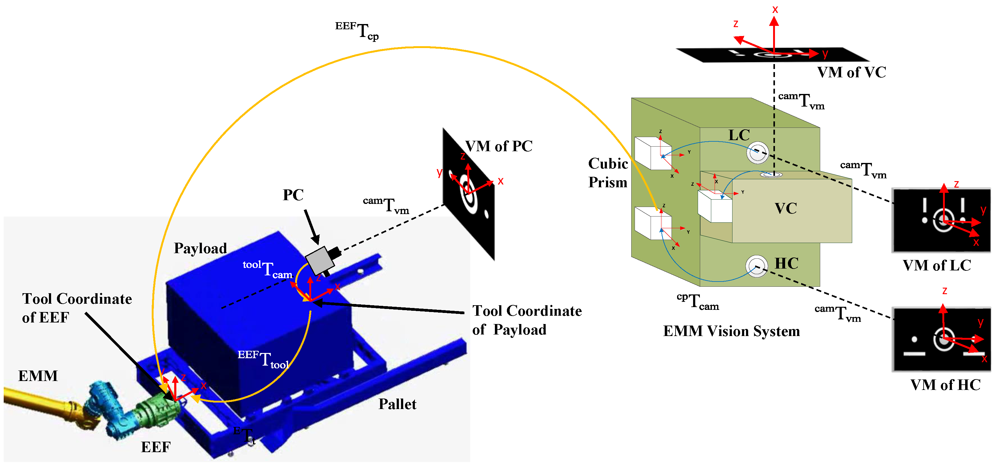
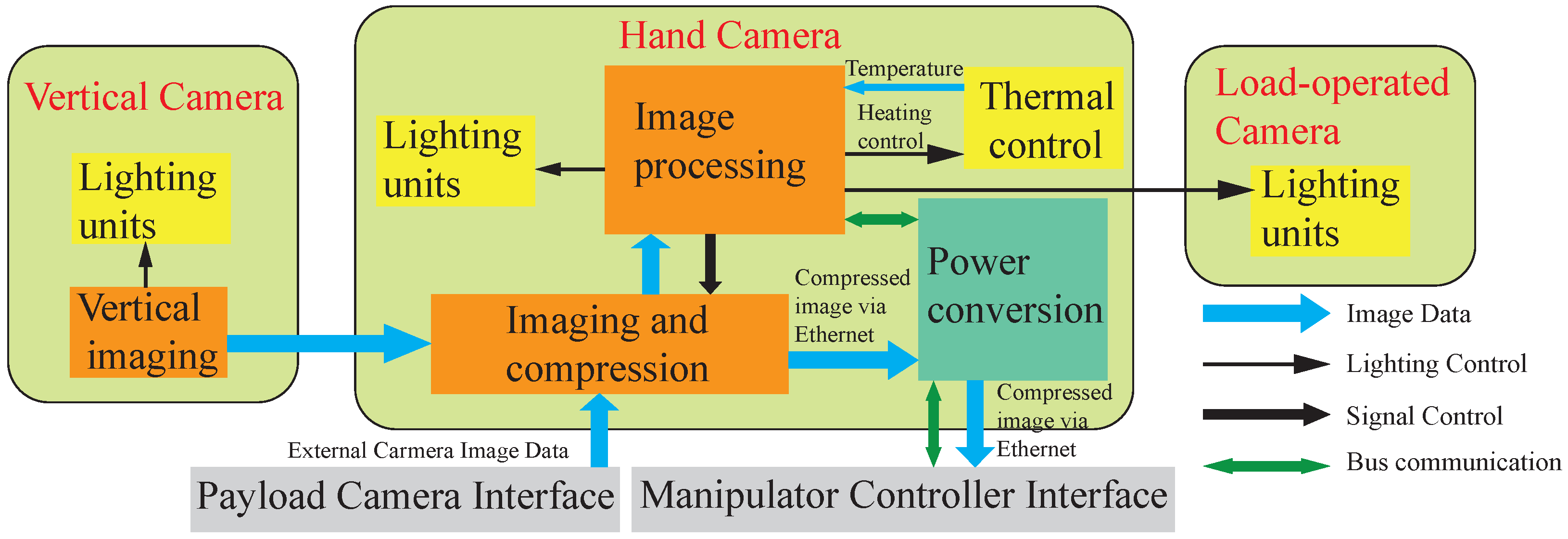
2.1. EMM Vision System

The EMM is a redundant seven-degree-of-freedom manipulator symmetrical about the elbow joint [37], with an identical EEF at each end, one of which acts as a base and can be connected to the module alone or to the CMM in a macro-micro way, while the other end is used to operate the payload. Each EEF is equipped with a vision system (short for EVS) primarily used to measure the attitude of the cooperative target and provide live image data. The EVS includes three separate optical systems called hand camera (HC), load-operated camera (LC), and vertical camera (VC). HC is located at the bottom for VS when the EFF is unloaded; LC is located at the top for the VS of small or medium-sized payloads when the hand camera is obscured; VC is mounted in a direction orthogonal to the other two cameras for VS of lateral payloads on the exposed platform. In addition, when the manipulator operates large payloads, such as pallets, a payload camera (PC) is mounted at the front of the pallet, as shown in Figure 2. The LC and VC use the same visual marker (VM), the others have different visual markers for the corresponding camera due to the working distance.
The architecture of the EVS is shown in Figure 3 with redundant backup for each unit. The HC is the interface and control centre of the vision system, the external camera image data interface with PC and compressed image data interface with the manipulator controller are implemented here. Each of the cameras has an independent lighting system but they share one processing and compression unit. The imaging of HC and LC share the same image processing unit. The VC and PC have the independent imaging units which are located in their own camera. The image processing item in Figure 3 is to perform a measure function to recognize the marker and calculate the relative pose. In addition, the image processor has an internal 1553B bus function that allows it to receive and forward various control commands from the central control; the information received includes image data, temperature data, and control signal, such as lighting control and heating control. The interaction of the camera information with the manipulator controller via an internal 1553B bus at a rate of 8 Hz, through which the manipulator controller sends commands to the EVS and receives the measurements. The camera imaging and process are based on FPGA. Image compression is based on DSP and transmission via the Ethernet at 25 frames per second.

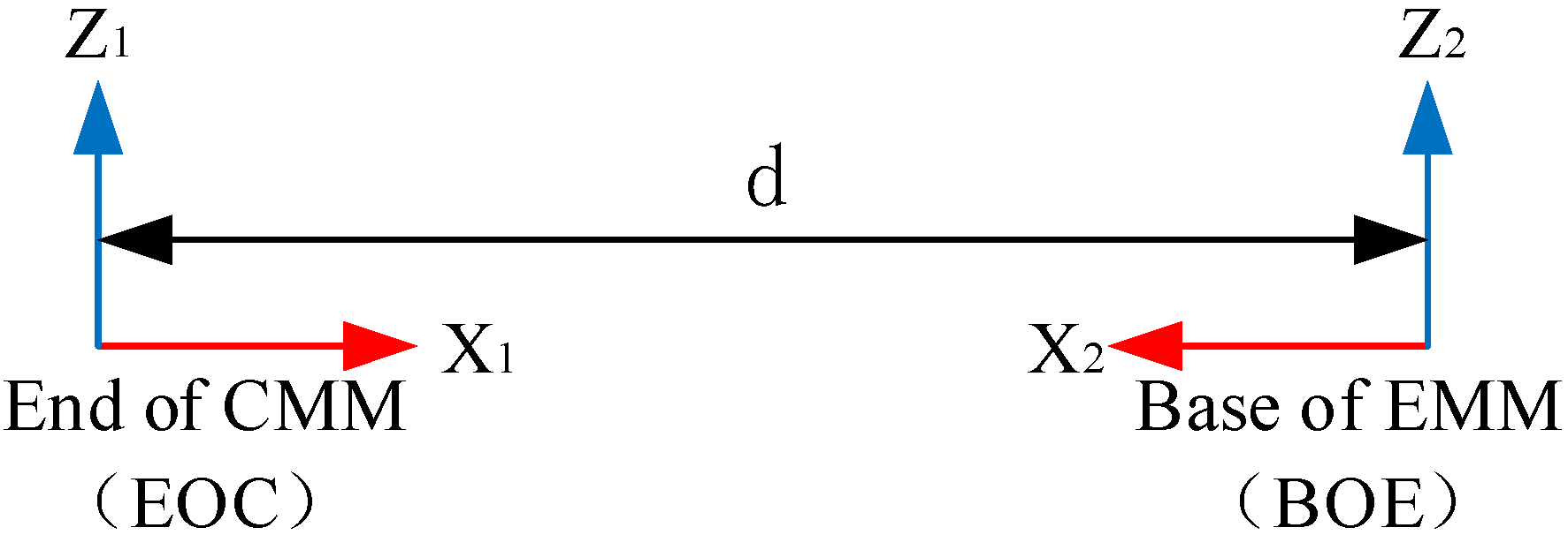
2.2. Measurement of Position and Orientation

The relative position and orientation from different targets to cameras are unified by the well-known intrinsic and extrinsic parameters. The intrinsic parameters matrix K satisfies:
Z c u ¯ v ¯ 1 = a x 0 u 0 0 a y u 0 0 0 1 X c Y c Z c = K P c
which is Z c P x = K P c , where a x = f c / d x , a y = f c / d y , and X c , Y c , Z c are the coordinates of three dimensional points in space; u ¯ , v ¯ are the coordinates of the ideal imaging point on the image plane in the image coordinate system; f c is the focal length; and a x , a y is the equivalent focal length of the camera in the x,y direction.
The position and orientation measured from the vision marker to the camera are expressed by transformation matrix cam T vm . The cubic prism is fixed on the EVS and used for the calibration from camera to cubic prism, which is represented as cp T cam . The EVS fixed on the EEF and matrices EEF T cp are calibrated from the cubic prism to the EEF tool coordinate. The pose information relative to the tool coordinate can be expressed as:
tool T vm = EEF T tool 1 · EEF T cp · cp T cam · cam T vm
where EEF T cam = EEF T cp · cp T cam is the extrinsic parameters, which are measured accurately “before” flight and do not change significantly “during” the flight. The control is proposed to move the payload to the desired position, tool d T vm is given as the desired berthing position relative to the visual marker coordinate, which is listed in the central controller through external command. Then, the servo error can be estimated in Equation (3):
tool d T tool = tool d T vm · tool T vm 1 = R e e p 0 1
The servo controller that minimizes the tracking errors is defined as e = e p T , e o T T 6 , where e p and e o are the position and orientation errors, respectively, where e o = θ a is computed by angle/axis parameterization for the rotation, which gives the minimum travel distance from the initial to the berth orientation and keep the marker at the center of the camera field of view.

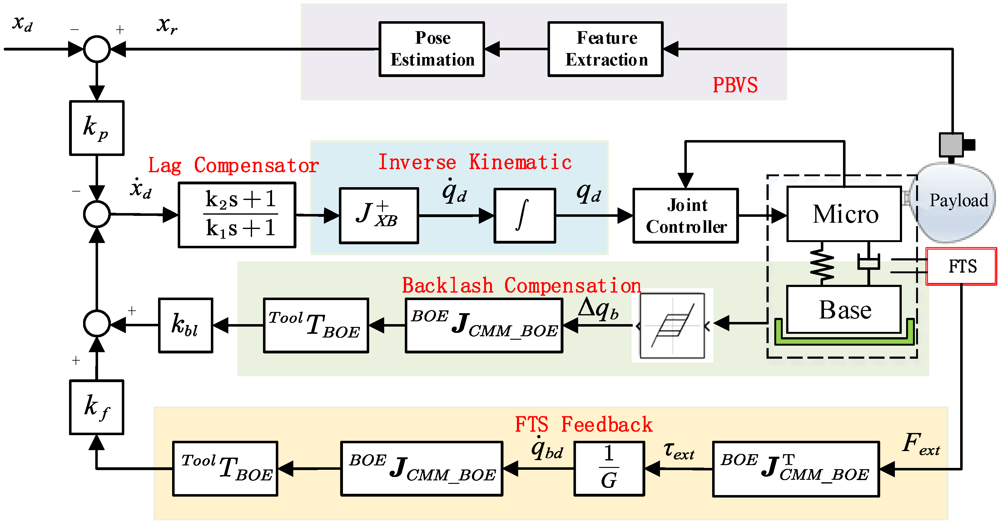
3. Integration of Visual Servo Control

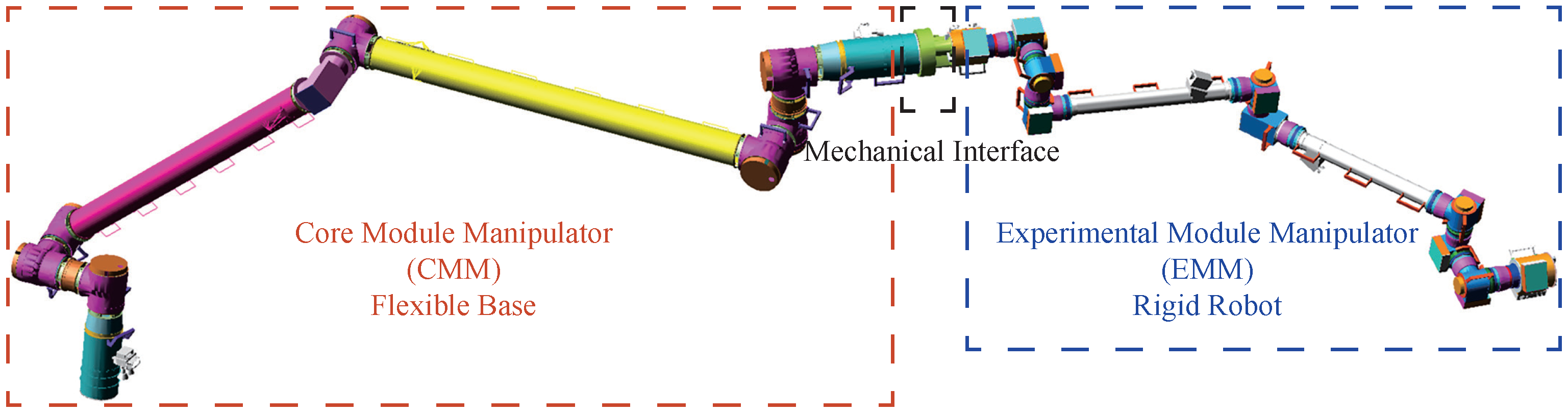
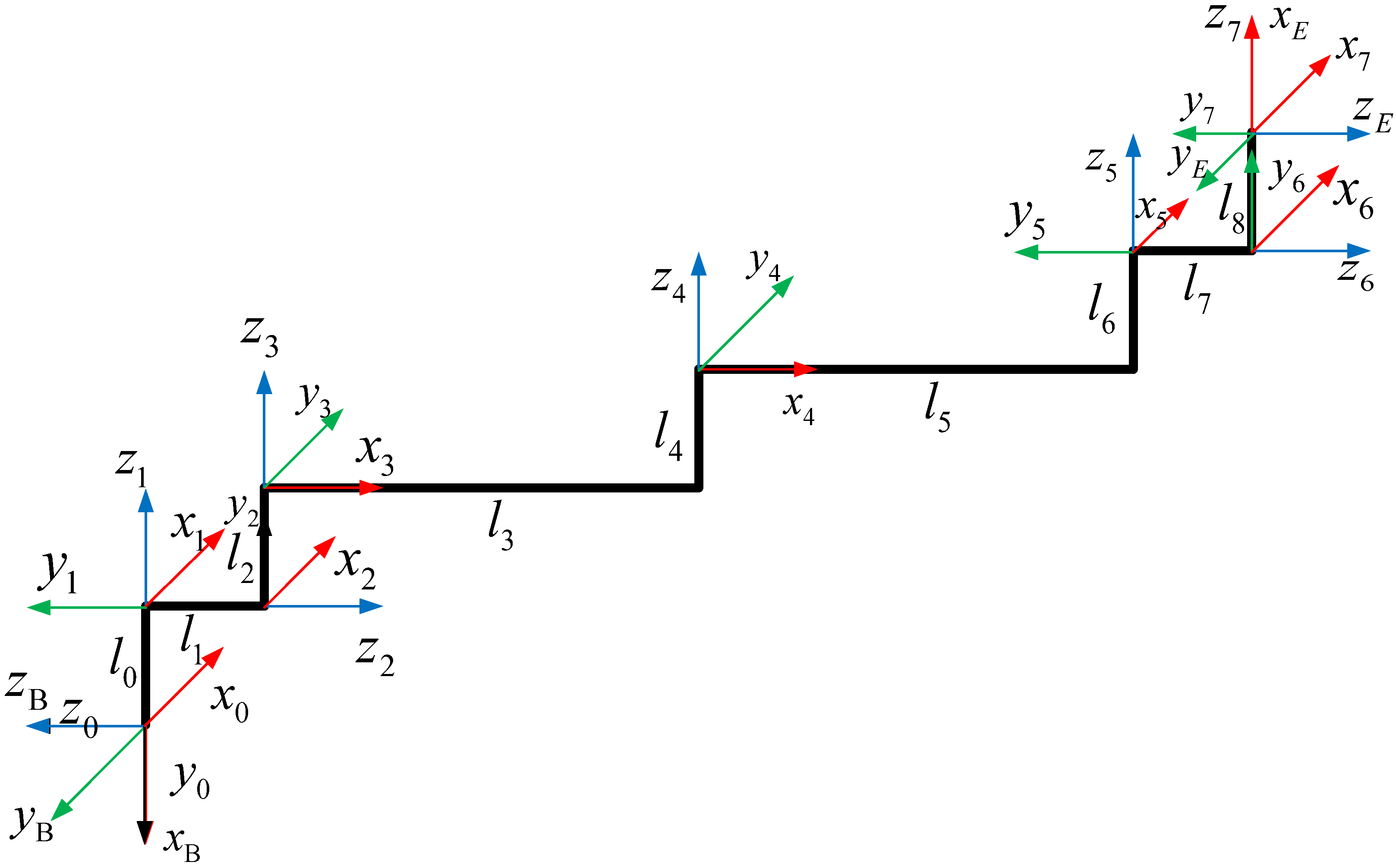
3.1. Model of Macro-Micro Manipulator

When the macro-micro manipulators are in series, the flexibility of the macro-manipulator is more important. Considering that the micro manipulator is stiff, the dynamic model is set up by the Lagrange equation with the generalized coordinates of the joints, as shown in Formulas (4) and ().
H b q ¨ b + H b m q ¨ m + C b + D b q ˙ b + K b Δ q b = 0
H b m T q ¨ b + H m q ¨ m + C m + D m q ˙ m = τ
where q b n b denotes the local coordinates of the macro-manipulator, q m n m stands for the joint coordinates of the micro-manipulator. The states of Δ q b are the current angles minus initial states. n b and n m are the DOF of the micro/macro manipulator, respectively. H b q b , q m n b × n b , D b n b × n b , and K b n b × n b denote base inertia, damping, and stiffness, respectively. H m q m n m × n m is the inertia matrix of the arm. H b m q b , q m n b × n m denotes the so-called inertia coupling matrix. C b q b , q ˙ b , q m , q ˙ m n b and C m q b , q ˙ b , q m , q ˙ m n m are velocity-dependent nonlinear terms, D m n m × n m denotes arm joint damping and torques, τ n m are considered the control inputs. It can be seen that no external forces are present, and this assumption holds throughout the paper.
The stiffness of the base joint K b is non-constant due to the gear backlash, as shown in Figure 4. The stiffness is not zero in the backlash due to the friction and lubrication. Outside the backlash, the stiffness is much more significant due to the flexibility of the gear reducer.
The working condition of the manipulator in orbit is complicated, the dynamic model given above is an ideal model, in order to specify the dynamic characteristic, the following two essential assumptions are needed.
Assumption 1.
No constrained motions are considered, which means the manipulator is under free space.
Assumption 2.
The joint friction is not considered, which means the deflection of the macro-manipulator will oscillate around zeros.

3.2. Reaction Force/Torque Feedback Control

The internal forces measured by the force/torque sensor F S is described in the installation coordinate and transformed to the EEF by:
F B = B R S 0 × B P S B R S B R S · F S
where P and R are the position and rotation matrix expressed in the reference frame sensor to EEF, F B represents the interaction force and torque from the manipulator motion. The forward direction is defined from joint to EFF.
A special mechanical interface (MI) between CMM and EMM combined the macro and micro manipulator in series. It consists of two different grapple fixtures for each manipulator. Each end of the mechanical interface corresponds to the end-effector of the CMM and EMM, respectively. The coordinate frame defined for the End of CMM (EOC) and Base of EMM (BOE) is shown in Figure 5.
The relation expressed in the transfer matrix is:
T MI = 1 0 0 d 0 1 0 0 0 0 1 0 0 0 0 1
The Jacobian of the CMM form BOE to the base of the macro-micro manipulator (BMM) is:
B M M J C M M _ B O E = I 3 B M M R C M M · P M I × B M M R C M M T 0 3 I 3 · B M M J C M M
where B M M J CMM and R CMM are expressed in the base coordinate frame of CMM. The calculation method regards the mechanical interface as the tool of the CMM. The deflection torque of the joints due to the reaction force is:
τ e x t = B O E J C M M _ B O E T · F B
where B O E J C M M _ B O E is the Jacobian of CMM with the mechanical interface and expressed in the coordinate of BOE.
B O E J C M M _ B O E = B O E R B M M 0 0 B O E R B M M · B M M J C M M _ B O E
It is essential to study the manipulator with a stationary initial state. Ignoring the force sensor’s elasticity in the model and treating it as an ideal force sensing element, from the dynamic Equation (4), the deflection dynamic can be striped as:
H b q ¨ b + K b Δ q b + C b = τ e x t
We can see from the base deflection dynamics that the base forces, which are measured by the FTS, reflect the motion of the base. The deflection forces depend on the robot’s state and the control input while performing the visual servo task. The desired closed-loop base deflection dynamic is:
H b q ¨ b + ( D b + G ) q ˙ b + K b Δ q b = 0
The base reaction forces are feedback to achieve the desired closed-loop dynamic, where a positive definite damping term G is added to damp out the base deflection:
q ˙ b d = τ e x t / G
Due to the slow deflection of the flexible base, the dynamic inertial forces of the macro manipulator can be neglected, the contribution of the joint deflection in the coordinate of BOE denoted by the FTS is:
B O E v B O E _ d = B O E J C M M _ B O E · q ˙ b d = B O E J C M M _ B O E · G 1 · B O E J C M M _ B O E T · F B
Then, the base deflection can be converted to the EEF by:
T o o l v f = T o o l T B O E · B O E v B O E _ d
where T o o l T B O E is the velocity convert matrix from the tool of the EMM to the BOE.
T o o l T B O E = B O E R T o o l T B O E R T o o l T · P t o o l × 0 B O E R T o o l T
The application process of base FTS is needed. Firstly, the macro-micro model is detected compared to the single-arm mode. Then, the FTS is enabled to the low-pass filter. The static judgment is needed to ensure there is no movement of the manipulator system at the initial states. Due to the zero-point drift of the FTS, the sensor is needed to reach zero for some conditions. Besides, a threshold is set due to the sensitivity limitation and noises. Finally, the visual servo control is carried out based on the base FTS feedback.

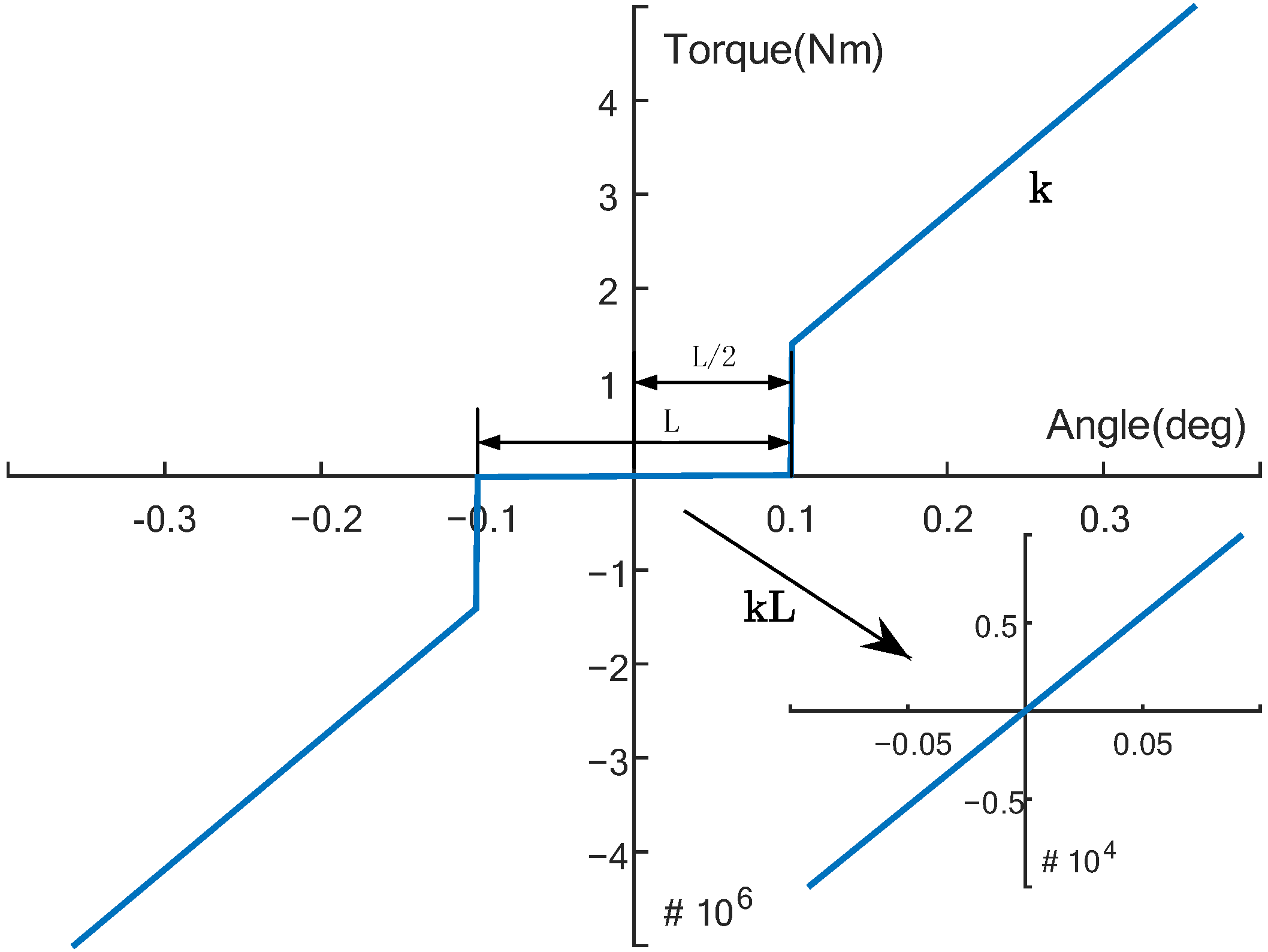
3.3. Base Backlash Compensation

Due to the low stiffness of the gear backlash, the joint deflection is much more sensitive to the reaction force/torque, and the backlash is not to be ignored. However, the force/torque sensor at the base of the EMM is inoperative for the minor response. Considering the working mode is the motor of the macro manipulator is fixed, the perception of the backlash can be executed by the fusion angle of the joint. The effect of backlash to the EFF can be calculated by:
T o o l e b l = T o o l T B O E · B O E J C M M _ B O E · Δ q b l
where Δ q b l is the angular difference by the initial joint angle minus the real joint angle.
It should be noted that the joint deflection feedback through FTS or directly through the joint angle are two different methods for different purposes. The FTS reveals the dynamic motion of the manipulator, it works when there is a wide range of disturbance due to the limited sensing accuracy, which is effective for the period of acceleration saltation. However, the backlash is a small deflection, and the compensation works when there is a small range of oscillation, this is essential for the period of residual oscillation when the visual errors approach zeros.

3.4. Integration of a Visual Servo

The visual servo control based on the base vibration suppression and base backlash compensation is introduced based on Equations (15) and (17).
T o o l v d = k p e + k f T o o l v f + k b l T o o l e b l
where the gain values k p , k f , and k b l are positive defined. k p is the coefficient that converges the tracking errors in the way of exponential convergent, k f and k b l are the coefficients that control the compensation errors in the task space. Then, the desired trajectory of the joints is resolved by the inverse kinematics of the EMM. Besides, the desired velocity T o o l v d expressed in the task space should be converted into the coordinates of BOE or use the Jacobian of T o o l J E M M .
Due to the low stiffness of the flexible base and large payload-to-manipulator mass radio, the low-frequency property is significant and the phase margin is meager. A lag compensator with time constants k 1 , k 2 is defined as k 2 s + 1 k 1 s + 1 to improve the closed-loop performance. The control block is shown in Figure 6.

3.5. Stability Analysis

The closed-loop visual servo system based on the proposed method can be written as:
e ˙ = k p e + k ¯ f Δ q ˙ b + k ¯ b l Δ q b
which:
k ¯ f = k f · T o o l T B O E · B O E J C M M _ B O E · G 1
k ¯ b l = k b · T o o l T B O E · B O E J C M M _ B O E
Assuming that the configuration of the manipulator is non-singular and the inverse kinetic solution of the redundant manipulator is closed-form without self-motion, which means e = 0 is the only solution of q m q d . When the EEF reaches the desired berth position, the base deflection should be damped to zero. The steady state convergence value of the visual error is e = e 0 exp k p t + ( k ¯ f Δ q ˙ b + k ¯ b l Δ q b ) / k p , in which it can be seen that the errors are exponential decay and the steady-states are affected by the base deflections. The final states of Δ q b are influenced by motion of the manipulator under the Assumptions of A1 and A2. The isolated equilibrium of the closed-loop system is Δ q b T Δ q ˙ b T e T T = 0 0 0 T . The configuration of the manipulators does not vary quickly compared with the elastic vibration, it is reasonable to treat the matrices as constant. Then, the closed-loop system can be described by the flowing state-space form:
Δ q ˙ b Δ q ¨ b e ˙ = 0 I 0 H b 1 K b H b 1 D b + G 0 k ¯ b l k ¯ f k p Δ q b Δ q ˙ b e
The stability of the overall system can be analyzed by investigating the poles of the closed-loop system, the eigenvalues are determined by the roots of the characteristic polynomial:
p λ = λ + k p λ 2 + H b 1 D b + G λ + H b 1 K b
It is sufficient to validate that all roots are contained in the left open complex half-plane when G is positive definite, it is globally asymptotically stable in the equilibrium.

4. Simulation Results

4.1. Simulation Model

This section presents the simulation results for the proposed control laws via the MMMS model. The kinematic models of the CMM and EMM are the same but with different link length parameters. The frames of the 7-DOF offset manipulator are shown in Figure 7, which are based on the modified D-H parameters in Table 1 where the subscripts B and E are the base and end of the manipulator, respectively. The CMM and EMM are connected in series by the MI shown in Figure 5. Due to the symmetry of the architecture, both manipulators can crawl on the space station, and the base or end of the manipulator can be reversed. Link 1 is physically formed by the combination of joint 3, lower arm boom, and joint 4. Link 2 is physically formed by the combination of the elbow joint, upper arm boom, and joint 5. We only consider the flexible booms of the CMM, and the link of EMM, and payload are approximated by rigid bodies. The viscous damping and joint torsional springs are included in all joints, which are modularized designed. The joint backlash of CMM is considered as Figure 4, where the backlash is L = 0.2 deg and stiffness and damping are listed in Table 2. The flexible boom is modeled as a hollow rod, with an elastic modulus of 90 GPa and a shear modulus of 34.6 GPa. The simulation model is built by ITI-SimulationX, where the inertial parameters and payload are listed in Table 3.
The visual servo simulation of the MMMS with a payload is performed, where the pallet camera is in front of the payload, as shown in Figure 2. The task is to move the payload out of the cargo spaceship and away from the pallet with the support of the EVS. We assume that the light condition is ideal and the Assumption of A1 is considered, which means there is no external contact force. The desired berth place is 3.5 m away in the X-direction. The initial configurations of the CMM is q b = ( 151 , 20 , 29 , 37 , 77 , 72 , 11 ) T deg and EMM is q m = ( 160 , 86.096 , 56.871 , 89.166 , 71.999 , 87.643 , 167.113 ) T deg with the joint order from base to end. The sampling time of the central controller and visual measure is 100 ms, the joint controller is 2 ms. Furthermore, an inherent time delay exists in the posture measuring and posture transferring due to the performance limitation of the EVS. A delay of 0.5 s is added in the visual feedback to simulate the time delay of the real physical system.
The velocity and acceleration limitations are imposed to avoid the sharp movement when the pose error is large at the beginning due to the fixed gain coefficient of k p . The max planned velocity and acceleration of the visual servo is (0.02 m/s, 1 deg/s) and (0.002 m/s 2 , 0.1 deg/s 2 ), respectively. The lag compensator is s + 1 8 s + 1 for the large payload, and the gain matrices were set as follows:
k p = 0.05 e y e ( 6 )
k f = 1 e y e ( 6 )
k b l = 0.2 e y e ( 6 )
G = 1 e 5 e y e ( 7 )

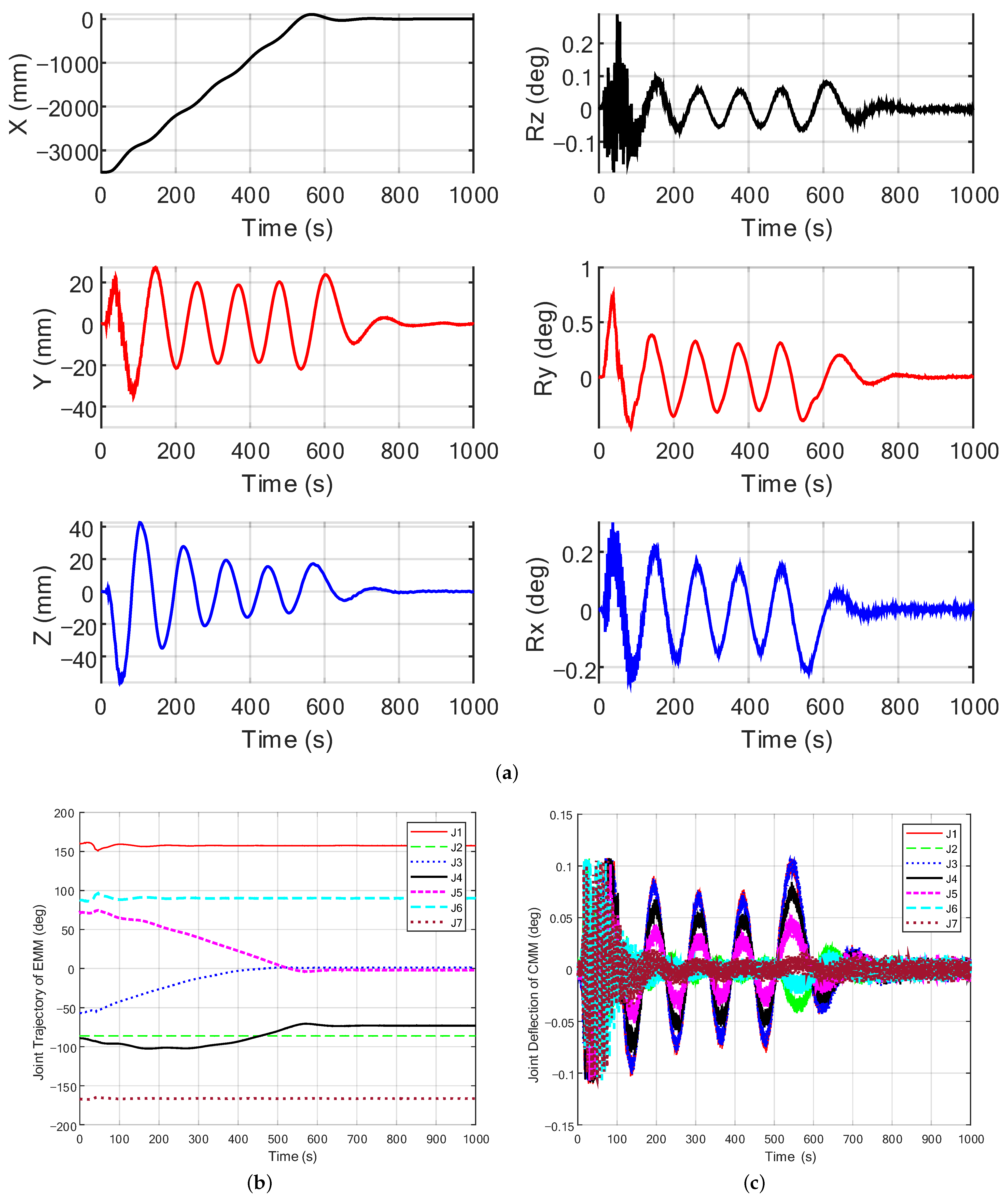
4.2. Simulation Results

The results from the simulation are shown in Figure 8, Figure 9 and Figure 10. In Figure 8a, we denote the relative position and orientation of the visual servo. (b) Denotes the joint angles of CMM and (c) denotes the joint deflections of CMM. Figure 9 denotes the deflection of the end of the CMM, which is described in the frame of the base of the MMMS. Assuming that the orientation of the EEF and object frames slowly vary with respect to time, we use the ZYX Euler angle to represent the orientations. From Figure 8a, it is seen that, under the visual servo control, the tracking errors are reduced at a relatively steady velocity in the long-range motion and converge to zeros when reaching the desired berth position within one vibration cycle. A low-frequency vibration appeared in the manipulator system due to the rather low natural frequency (0.007 Hz). As shown in Figure 8c, the joint of the CMM mostly moves within ± 0 . 1 , which is the boundary of the backlash. The joint motion of the CMM will reverse at the backlash boundaries due to a higher stiffness, which will work beyond the backlash. Even though the backlash is small, the deflection of the CMM is nonnegligible, which can be seen in Figure 10. However, with the backlash compensation, the deflection of the CMM converges to zeros when the EEF reaches the desired target. One can see that, acceleration during the start-up period and deceleration near the target period will stimulate the deflection in the backlash. From Figure 9, it can be seen that, at the beginning of the acceleration period, the motion of the EMM inevitably causes a disturbance to the base, leading to the joint oscillation of the CMM in the backlash, the base vibration based on the FTS works at this period due to the dead zone limitation of the FTS. The joint trajectory of EMM is performed with the joint two fixed inverse kinematics, as shown in Figure 8b.

5. Experimental Results

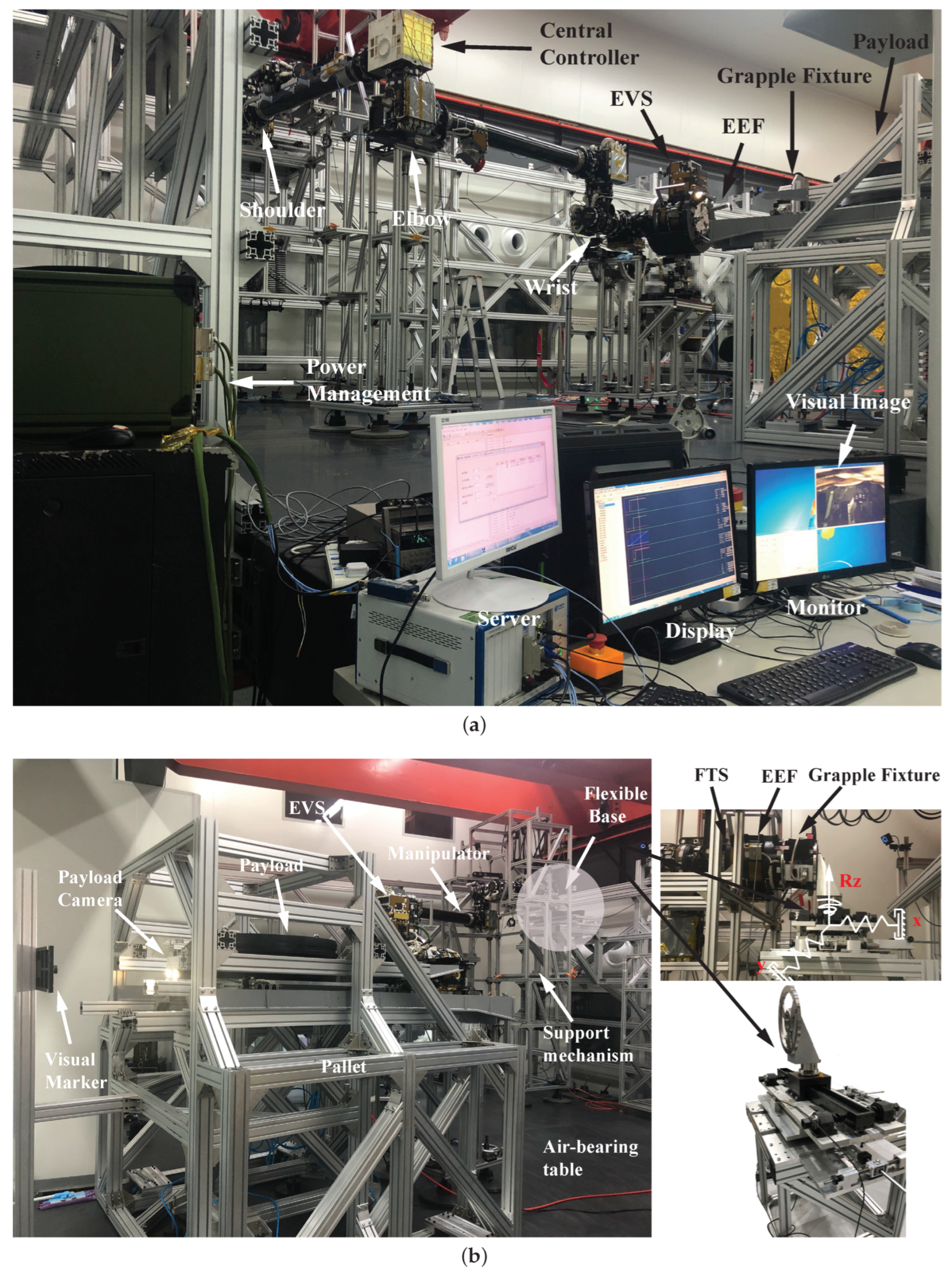
5.1. The Experimental Facility

In this section, the test-bed used in this research is described in detail. Considering the high experimental cost of the MMMS, a tunable planar flexible base with three degrees of freedom is designed, which includes a two-dimensional motion platform carrying the linear variable stiffness module (containing X and Y directions) and one rotation (Rz direction) variable stiffness module, as shown in the right picture of Figure 11b. The stiffness can be adjusted corresponding to different configurations of macro manipulators. An inherent slight backlash is added in the three directions due to the mechanical structure, but the real-time base backlash compensation is not included.
A prototypical manipulator of EMM is connected with the flexible base and is supported on the air-bearing table. The manipulator is constrained to move in the horizontal plane, only the three parallel joints of the manipulator can rotate, which is equivalent to a three-link manipulator. The configuration from 1 to 7 is [ 90 , 90 , w r i s t , e l b o w , s h o u l d e r , 90 , 90 ] T deg, as shown in the sub-figure of Figure 11a. The joints are supported by the micro-gravity compensation system, the EEF (including FTS) near joint 7 (shown in left top picture of Figure 11b) is connected with the flexible base. The detail of the FTS used in the experiment has been exhibited in [33]. The EEF near joint 1 can be connected with the payload. Figure 11a shows the scenario of the empty load visual servo, where the payload is fixed on the ground. A grapple figure is mounted in the back of the payload, the VM of the HC is installed on the grapple fixture, which is shown in [9]. The left picture of Figure 11b shows the scenario of the 1500 kg load visual servo, where the EEF connected with the grapple fixture. HC is obscured by the large payload and the PC will work.
The software of the manipulator system includes communication, imaging, visual measurement, active thermal control, motion, power management, fault detection and handling, software maintenance and update, and task list management. The control system of the manipulator is distributed, where the central controller is fixed on the elbow joint, as shown in Figure 11a. Controllers of the joints and central controller are all based on the BM3803 and FPGA. The console, consisting of a server, display, and monitor, is connected based on Ethernet. The primary task processing process is that the central controller parses the control commands and control parameters on the manipulator’s dedicated 1553B bus, as well as the real-time calculation results, and controls the joints, effectors (including FTS), and end cameras, respectively, via the arm’s internal 1553B bus to complete the specified arm system tasks. After the task is completed, the arm software system returns to a non-working state or a safe or standby mode state, as required, pending the next task.
Interpolation is required between the camera, central controller, and joints due to the different performance of the processors. The frequency of the posture measurement, central controller, and joint controller is 8 Hz, 10 Hz, and 500 Hz, respectively. The posture measurements obtained from EVS are widened to 10 Hz. The desired joint angles calculated in the central controller are interpolated in the joint controller every 50 times. The joint controllers are PD-based motor control with a steady closed-loop control accuracy of better than 0.025 deg. The sensors’ data are stored in the server at a frequency of 10 Hz for the fast telemetry.
Two cases of experiments have been performed based on the flexible base manipulator testbed. First is the no-load visual servo based on the HC; second is the large payload visual servo based on the PC. Here, we assume no contact between payload and pallet. The visual marker is ahead of the camera, and two desired berth positions are planned to reach the final target. The manipulator approaches the target and moves away from it to demonstrate the in-orbitobit task, which is divided into four trajectories in different directions. As shown in the results, the green vertical dotted line is the beginning time, and the black one is the stop time. The visual measures and base FTS are monitored. The visual measure accuracy of HC is (0.5 mm, 0.3 deg) to (1.5 mm, 0.5 deg), and PC is (2 mm, 0.5 deg) to (5 mm, 1 deg), which is related to the working distance. The resolution of the cameras is (0.1 mm, 0.1 deg), the threshold of sensitivity of the FTS is (2 N, 2 N, 2 Nm). A comparison results of the two cases are listed in Table 4.

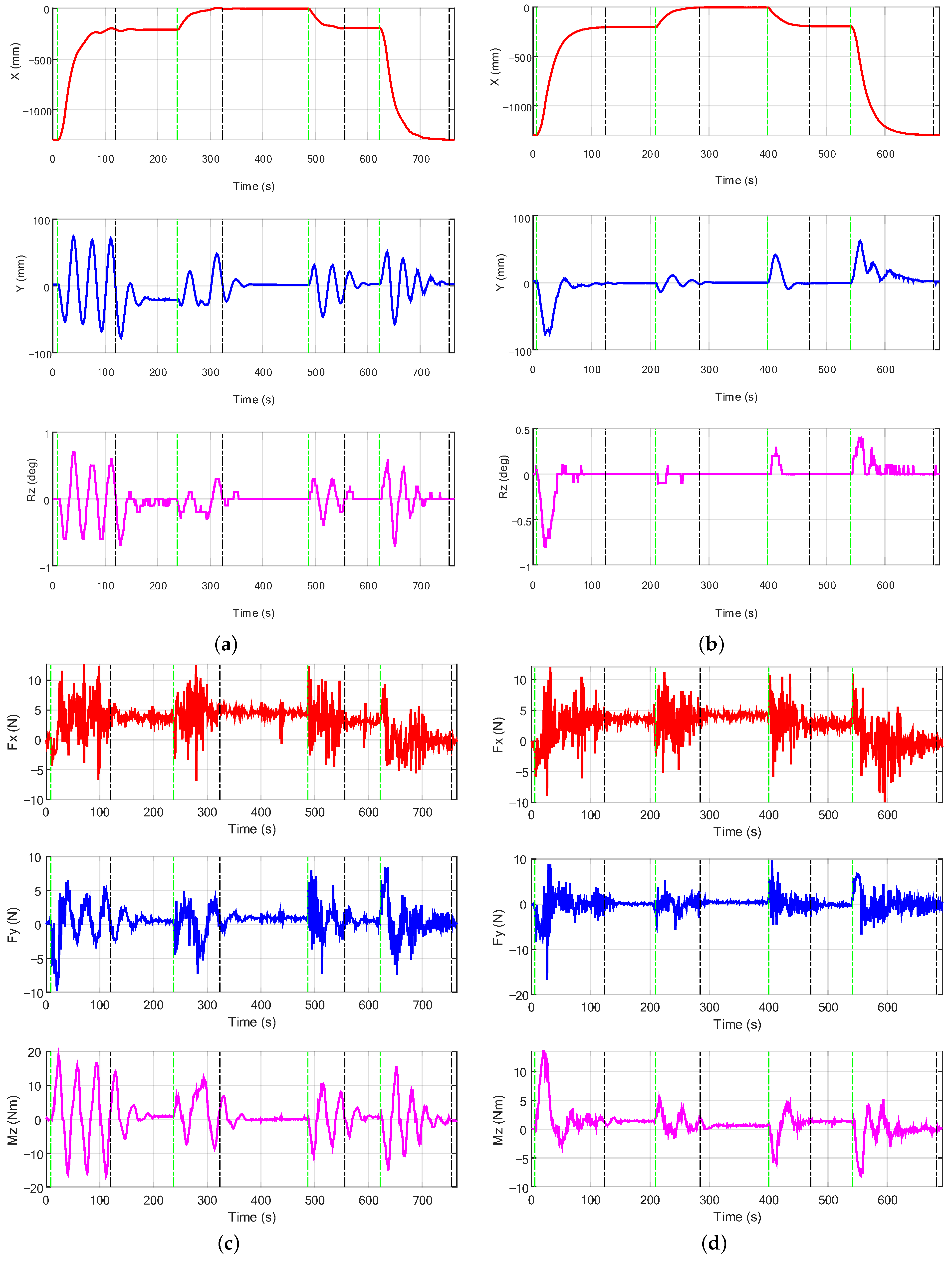
5.2. Visual Servo Control without Payload

Case 1 is the visual servo without a payload mounted on the EEF. The stiffness in X, Y, and RZ of the flexible base is 1.6375 N/mm, 8.158 N/mm, 529 Nm/deg, respectively. The control gains are Kp = (0.032, 0.048, 0.05) and G = 17,000. The max planned velocity and acceleration of the visual servo are (0.02 m/s, 1 deg/s) and (0.001 m/s 2 , 0.05 deg/s 2 ). No extra lag compensator is needed due to the small disturbance to the flexible base. The initial distance in the X-direction is 1000 mm, and the intermediate berth is 120 mm. The initial configuration of the wrist, elbow, and shoulder is (39, −96, −100) deg. The visual servo control will finish when the tracking errors in X, Y, and Rz are less than (3 mm, 3 mm, 0.3 deg), showing that the manipulator reaches the desired berth position.
The experimental results for case 1 are given in Figure 12, in Figure 12a,c there is no vibration suppression algorithm, while the right Figure 12b,d is based on FTS feedback. Figure 12a,b show the position error (x-axis and y-axis) and orientation error (Euler angles representation), respectively, with respect to the desired relative position to the HC markers. The visual measure results show that the EEF’s motion speeds up and then slows down exponentially, and the visual control is finished normally in each trajectory. The visual errors shown in Table 4 are similar due to the measurement accuracy and resolution limitation. The difference of the trajectory in the x-axis is not obvious because the motion of the EEF is slanted to the y-axis (expressed in the coordinate of BOE). As the stiffness of the base in the y-axis is larger than the x-axis, the higher fundamental frequency is as expected without payload, which means the vibration control does not promote the tracking accuracy under the higher fundamental frequency; the dominant factor is the measurement accuracy and resolution limitation.
One can notice that the visual error of the y-axis is significantly suppressed, and the time of the oscillation during each motion is shortened from the initial 8 cycles to about 1 cycle. Similar results of contrast are shown in Figure 12c,d, where the forces (x-axis and y-axis) and torque (Mz) of the base FTS, which is represented in the coordinate of BOE. From the comparison of Mz, it can be seen that the base vibration is quickly suppressed after one period of vibration, the FTS-based suppression works very well. One can notice, the reaction torque of Mz is relevant to the visual tracking errors of the y-axis, the base vibration suppression algorithm can effectively suppress the base disturbance and reduce the measured oscillation period of the EEF. Furthermore, we compare the total VS time under the zero payload condition, as shown in Table 4. It should be mentioned that the total servo time of the four trajectories is not necessarily related to whether or not the vibration control is used. When the servo control stability is guaranteed, the exponential convergence method of the tracking errors is the major contributors to the servo time.

5.3. Visual Servo Control with Large Payload

Case 2 is the large payload visual servo comparison with and without vibration suppression. In order to verify that the control effect is more significant and robust to different stiffness, the manipulator carries a 1500 kg load at a maximum planning speed of 50 mm/s in free space. A new stiffness in X, Y, and RZ of the flexible base is 1.046 N/mm, 2.3155 N/mm, and 120.91 Nm/deg, respectively. The frequency of the system in the configuration of (−155, 0, −90) deg is (0.0875, 0.035) in the X and Y directions, which is expressed in the coordinate of BOE. The control gains are Kp = (0.05, 0.05, 0.05) and G = 17,000. The max planned velocity and acceleration of the visual servo is (0.05 m/s, 0.5 deg/s) and (0.003 m/s 2 , 0.05 deg/s 2 ). The extra lag compensator is needed, which is s + 1 4 s + 1 . The camera of HC is sheltered and the PC is needed, which is mounted in front of the payload. The initial distance in the X direction is 1100 mm, and the intermediate berth is 200 mm. The initial configuration of the wrist, elbow, and shoulder is (−55, −102, −89) deg. The visual servo exit threshold is set to (5 mm, 5 mm, 0.3 deg) due to the different accuracy of the cameras.
The experimental results for case 2 are given in Figure 13, the left Figure 13a,c has no vibration suppression algorithm, the right Figure 13b,d is based on FTS feedback. Figure 13a,b show the position error (x-axis and y-axis) and error (Euler angles representation), respectively, with respect to the desired relative position of the tool coordinates of payload to the VM of PC. The vibration reflected in the visual errors in Figure 13a is obvious compared to the empty load condition in Figure 12a, due to the lower fundamental frequency and higher motion speed. One can notice in the first trajectory, in the time from 7 s to 118 s, the servo control stopped abnormally after three swing periods, causing the visual measure errors to fluctuate until 190 s; it is obvious that the VS without vibration control will take a long time to wait for the vibration to fade away, as shown in Table 4. The total servo time of the four trajectories is much longer if there is no vibration suppression. It can be seen that the visual servo without vibration suppression has a large end oscillation at high speed and is difficult to attenuate, which may cause the camera to lose the target, leading to the termination of the visual servo motion, causing unnecessary disturbances, as shown in Table 4. The servo errors in the x-axis are 12 mm beyond the target, as a comparison, the overshoot in the X direction is avoided with the suppression algorithm, and dampen the non-forward direction (y-axis and Rz); thus, the vibration period basically decays from 4 to 1. Naturally, the time cost is lower, for example, it takes only 120 s to finish the first trajectory, reduced by 37%.
The vibration suppression-based visual servo algorithm reduces the disturbance torque on the base (Figure 13d) from 18 Nm to 13.5 Nm, decreases the swing frequency of the load, and reduces the magnitude of the lateral swing to a certain extent to ensure that the target is within the field of view of the camera and improves the reliability of the visual servo tracking algorithm. One can notice that the visual error of the y-axis is significantly suppressed and the x-direction is smooth in Figure 13b. It should be noted that the deflection of the visual errors in the first half period of vibration is inevitable, even though the vibration will be damped rapidly, as shown in the Y-axis and Rz-axis. A reasonable interpretation is that the system’s natural frequency is low, and the response bandwidth of the manipulator is not enough to instantly compensate for the visual errors, even though the manipulator has one redundant DOF for compensating for different directions of motion. In general, it can be seen that the swing period, which is reduced, enables the flexible base manipulator system to stabilize faster when the visual servo enters the exit domain and switches to standby mode, improving the positioning accuracy of servo control.

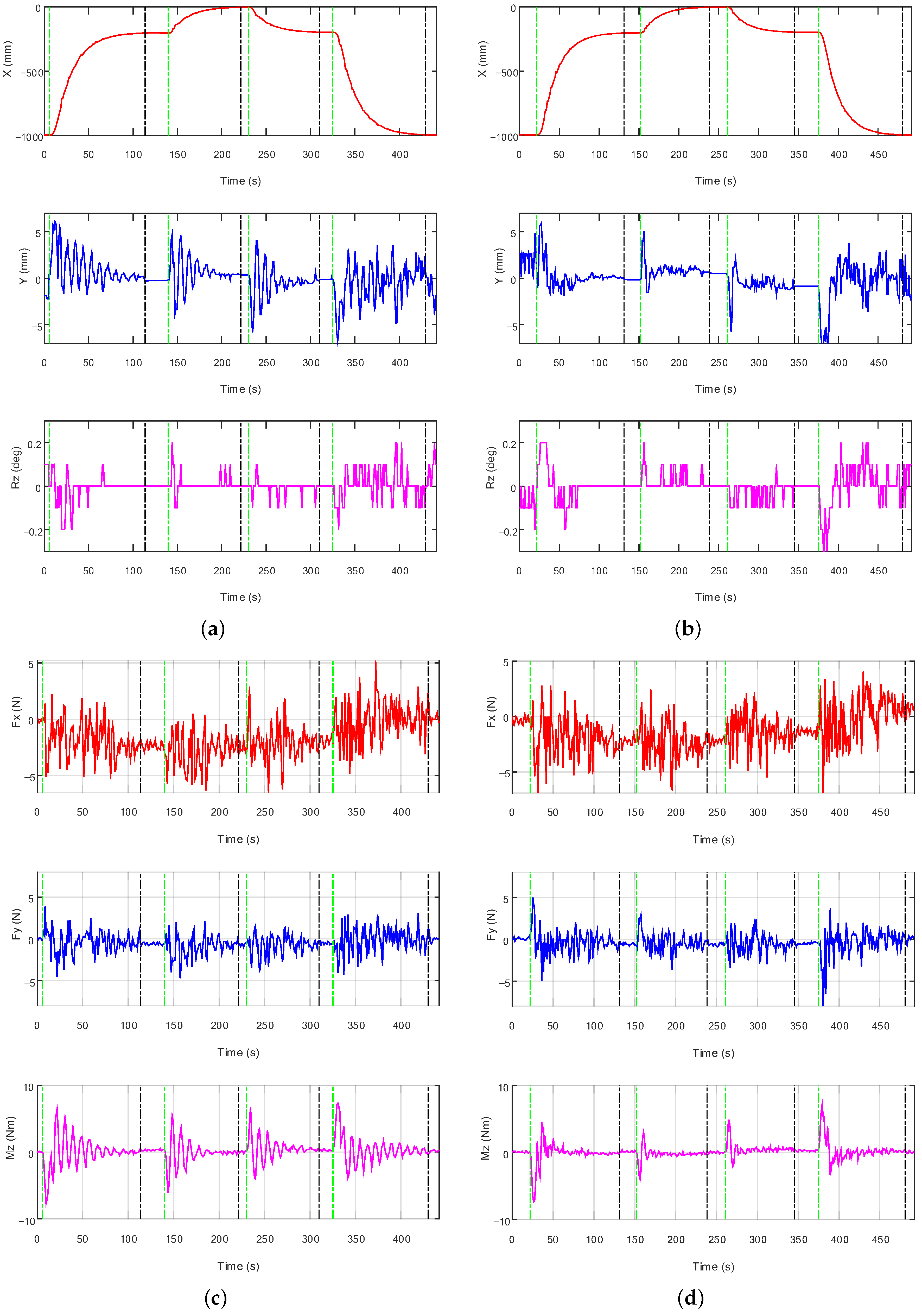
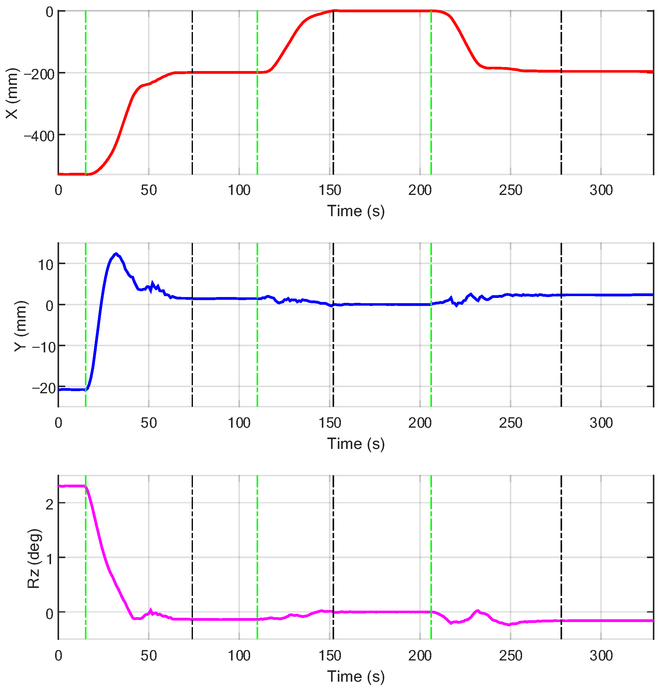
5.4. Visual Servo Control of MMMS

To further verify the effectiveness of the real time joint backlash compensation, we subsequently validated the visual servo algorithm on the planar MMMS test-bed. Comparing with the previous test-bed of FBMS, the flexible base is replaced by a prototypical manipulator of CMM [38], and the EMM is joined together through the mechanical interface on a larger air-bearing table. The power supply and communication is rebuilt in the “Macro-Micro Mode”, where the 1553B bus of the two manipulators are connected, and the manipulators are commanded through the operating consoles.
The experimental scenarios were designed in three trajectories to move between the “coarse” and “fine” position, where the coarse position is 200 mm ahead of the fine position. There are initial errors of −528 mm, −21 mm, and 2.3 deg in the X, Y, and Rz, respectively. The visual servo results shown in Figure 14 are tested without payload. It can be seen that the controller is stable in different trajectories, and the final berth accuracy is less than (3 mm, 3 mm, 0.3 deg). One can notice that the gradual deceleration works when the manipulator approaches the target; at the same time, the max overshoot of 12 mm in the Y-direction is apparent, which gradually converges to zero and no widespread fluctuations are generated.

6. Conclusions

In this paper, we analyzed the visual servo control problem of the macro-micro manipulator system with large payloads, in which the force/torque sensor (FTS) is mounted at the base of the micro-manipulator. An integrated controller was proposed, including exponential convergence of visual errors, backlash compensation, and vibration suppression. The base deflection can be perceived by FTS in the large deflection or by joint sensors in slight backlash, and a dynamic model is not needed. A prototypic implementation of the vision servo system of the Experimental Module Arm has been shown. A simulation model with a large payload was established for the macro-micro manipulator in-orbit operation task, and the integrated control strategy was verified. The planar flexible base manipulator system was set up for ground experimental verification, and the visual servo experiments were carried out. The effectiveness of the vibration suppression is demonstrated based on the proposed methodology under different stiffness and payload conditions. The vibration periods decay from four to one and the servo time was reduced 37%. Further, the joint backlash compensation algorithm is validated based on the ground MMMS test-bed. Test results confirmed the efficacy and robustness of the control approach, ensuring the reliability and improving the efficiency of the VS.
There are still some limitations due to the assumptions. We consider no constrained motions, in practical application, the contact may occur in the rapid and precise positioning of the payload, especially for the payload in the pallet. Moreover, the joint friction in the backlash is not considered, in practical, the static friction in the backlash will work if the reaction force is low enough. The static equilibrium will change and cause a steady error of the visual control. In future work, the isolated static equilibrium should be reconsidered, and visual impedance can be investigated further.

Author Contributions

Conceptualization, Y.Z. and Y.L. (Yechao Liu); methodology, Y.Z.; software, Y.Z. and Y.L. (Yechao Liu); simulations, Y.Z.; experiments, Y.Z., Y.L. (Yang Liu) and B.C.; data collation, Y.L. (Yang Liu) and B.C.; resources and project administration, Z.X. and H.L.; writing—original draft preparation, Y.Z.; writing—review and editing, Y.L. (Yang Liu), Y.L. (Yechao Liu) and B.C.; visualization, Y.Z. All authors have read and agreed to the published version of the manuscript.

Funding

This work was partially supported by the Foundation for Innovative Research Groups of the National Natural Science Foundation of China (Grant No. 91848202) and the Special Foundation (Pre-Station) of China Postdoctoral Science (Grant No. 2021TQ0089, 2021M690826).

Institutional Review Board Statement

Not applicable.

Informed Consent Statement

Informed consent was obtained from all subjects involved in the study.

Data Availability Statement

Not applicable.

Acknowledgments

We would like to thank Changchun Institute of Optics, Fine Mechanics and Physics (CIOMP), and Beijing Key Laboratory of Intelligent Space Robotic System Technology and Applications, for providing the experimental site and cooperative unit.

Conflicts of Interest

The authors declare no conflict of interest.

Abbreviations

The following abbreviations are used in this manuscript:
FBMSFlexible base manipulator system
PBVSPosition-based visual servo
IBVSImage-based visual servo
DOFDegree of freedom
CMMCore module manipulator
EMMExperimental module manipulator
EVAExtravehicular activities
MMMSMacro/micro manipulator system
EEFEnd-effector
VMVisual Marker
HCHand Camera
LCLoad-operated Camera
VCVertical Camera
PCPayload Camera
FTSSix-axis force/torque sensor
EVSExperimental module arm vision system
EOCEnd of CMM
BOEBase of EMM
BMMBase of the macro-micro manipulator

References

  1. Waldron, K.; Schmiedeler, J. Kinematics. In Springer Handbook of Robotics; Springer: Berlin/Heidelberg, Germany, 2008; pp. 1423–1461. [Google Scholar]
  2. Liu, H. An overview of the space robotics progress in China. In Proceedings of the 12th International Symposium on Artificial Intelligence, Robotics and Automation in Space (i-SAIRAS 2014), Montreal, QC, Canada, 17–19 June 2014. [Google Scholar]
  3. Sharon, A.; Hogan, N.; Hardt, D.E. The Macro/Micro Manipulator: An Improved Architecture for Robot Control. Robot. Comput.-Integr. Manuf. 1993, 10, 209–222. [Google Scholar] [CrossRef] [Green Version]
  4. Laryssa, P.; Lindsay, E.; Layi, O.; Marius, O.; Nara, K.; Aris, L.; Ed, T. International space station robotics: A comparative study of ERA, JEMRMS and MSS. In Proceedings of the 7th ESA Workshop on Advanced Space Technologies for Robotics and Automation, Noordwijk, The Netherlands, 19–21 November 2002; pp. 19–21. [Google Scholar]
  5. Sato, N.; Wakabayashi, Y. JEMRMS design features and topics from testing. In Proceedings of the 6th International Symposium on Artificial Intelligence, Robotics and Automation in Space (iSAIRAS), Montreal, QC, Canada, 18–22 June 2001. [Google Scholar]
  6. Wakabayashi, Y.; Morimoto, H.; Satoh, N.; Hayashi, M.; Aiko, Y.; Suzuki, M. Performance of Japanese robotic arms of the international space station. IFAC Proc. Vol. 2002, 35, 115–120. [Google Scholar] [CrossRef]
  7. Flandin, G.; Chaumette, F.; Marchand, E. Eye-in-Hand/Eye-to-Hand Cooperation for Visual Servoing. In Proceedings of the International Conference on Robotics and Automation, San Francisco, CA, USA, 24–28 April 2000; pp. 2741–2746. [Google Scholar]
  8. Chaumette, F.; Hutchinson, S. Visual Servo Control. I. Basic Approaches. IEEE Robot. Autom. Mag. 2006, 13, 82–90. [Google Scholar] [CrossRef]
  9. Sun, K.; Liu, H.; Xie, Z.; Ni, F. Structure Design of an End-Effector for the Chinese Space Station Experimental Module Manipulator. In Proceedings of the 12th International Symposium on Artificial Intelligence, Robotics and Automation in Space, Montreal, QC, Canada, 17–19 June 2014; pp. 1–8. [Google Scholar]
  10. Wilson, W.; Hulls, C.; Bell, G. Relative end-effector control using cartesian position-based visual servoing. IEEE Trans. Robot. Autom. 1996, 12, 684–696. [Google Scholar] [CrossRef]
  11. Deng, L.; Janabi-Sharifi, F.; Wilson, W. Stability and robustness of visual servoing methods. In Proceedings of the 2002 IEEE International Conference on Robotics and Automation, Washington, DC, USA, 11–15 May 2002; pp. 1604–1609. [Google Scholar]
  12. Singer, N.C.; Seering, W.P. Preshaping command inputs to reduce system vibration. J. Dyn. Syst. Meas. Control 1990, 112, 76–82. [Google Scholar] [CrossRef]
  13. Sawada, H.; Konoue, K.; Matunaga, S.; Ueno, H.; Oda, M. Input Shaping Experiment for Damping Vibration in Manual Operation of a Large Robotic Arm. In Proceedings of the 8th International Symposium on Artificial Intelligence, Robotics, and Automation in Space, Munich, Germany, 5–8 September 2005; pp. 537–542. [Google Scholar]
  14. Cannon, D.; Magee, D.; Book, W.J.; Lew, J.Y. Experimental Study on Micro/Macro Manipulator Vibration Control. In Proceedings of the IEEE International Conference on Robotics and Automation, Minneapolis, MN, USA, 22–28 April 1996; Volume 3, pp. 2549–2554. [Google Scholar]
  15. Damaren, C.J. Approximate Inverse Dynamics and Passive Feedback for Flexible Manipulators with Large Payloads. IEEE Trans. Robot. Autom. 1996, 12, 131–138. [Google Scholar] [CrossRef] [Green Version]
  16. Christoforou, E.G.; Damaren, C.J. A passivity-based control case study of flexible-link manipulators. In Proceedings of the 2005 IEEE International Conference on Robotics and Automation, Barcelona, Spain, 18–22 April 2005; pp. 1005–1010. [Google Scholar]
  17. Stieber, M.E.; Mckay, M.; Vukovich, G. Vision-Based Sensing and Control for Space Robotics Applications. IEEE Trans. Instrum. Meas. 1999, 48, 807–812. [Google Scholar] [CrossRef] [Green Version]
  18. Lew, J.Y.; Moon, S.M. A Simple Active Damping Control for Compliant Base Manipulators. IEEE/ASME Trans. Mechatron. 2001, 6, 305–310. [Google Scholar] [CrossRef]
  19. George, L.E.; Book, W.J. Inertial Vibration Damping Control of a Flexible Base Manipulator. IEEE/ASME Trans. Mechatron. 2003, 8, 268–271. [Google Scholar] [CrossRef]
  20. Book, W.J.; Lee, S.H. Vibration Control of A Large Flexible Manipulator by A Small Robotic Arm. In Proceedings of the American Control Conference, Pittsburgh, PA, USA, 21–23 June 1989; pp. 1377–1380. [Google Scholar]
  21. Bascetta, L.; Rocco, P. Task Space Visual Servoing of Eye-in-Hand Flexible Manipulators. In Proceedings of the IEEE/ASME International Conference on Advanced Intelligent Mechatronics (AIM 2003), Kobe, Japan, 20–24 July 2003; Volume 2, pp. 1442–1448. [Google Scholar]
  22. Bascetta, L.; Rocco, P. Tip Position Control of Flexible Manipulators through Visual Servoing. In Proceeding of the 6th International Conference on Dynamics and Control of Systems and Structures in Space, Liguria, Italy, 17–21 July 2004; pp. 673–682. [Google Scholar]
  23. Bascetta, L.; Rocco, P. End-Point Vibration Sensing of Planar Flexible Manipulators through Visual Servoing. Mechatronics 2006, 16, 221–232. [Google Scholar] [CrossRef]
  24. Bascetta, L.; Rocco, P. Two-Time Scale Visual Servoing of Eye-in-Hand Flexible Manipulators. IEEE Trans. Robot. 2006, 22, 818–830. [Google Scholar] [CrossRef]
  25. Jiang, X.; Konno, A.; Uchiyama, M. A Vision-Based Endpoint Trajectory and Vibration Control for Flexible Manipulators. In Proceedings of the IEEE International Conference on Robotics and Automation, Roma, Italy, 10–14 April 2007; pp. 3427–3432. [Google Scholar]
  26. Cui, L.; Wang, H.; Liang, X.; Wang, J.; Chen, W. Visual Servoing of a Flexible Aerial Refueling Boom With an Eye-in-Hand Camera. IEEE Trans. Syst. Man Cybern. Syst. 2020, 51, 6282–6292. [Google Scholar] [CrossRef]
  27. Torres, M.A.; Dubowsky, S.; Pisoni, A.C. Vibration Control of Deployment Structures’ Long-Reach Space Manipulators: The P-PED Method. In Proceedings of the IEEE International Conference on Robotics and Automation, Minneapolis, MN, USA, 22–28 April 1996; Volume 3, pp. 2498–2504. [Google Scholar]
  28. Nenchev, D.N.; Yoshida, K.; Vichitkulsawat, P.; Uchiyama, M. Reaction null-space control of flexible structure mounted manipulator systems. IEEE Trans. Robot. Autom. 1999, 15, 1011–1023. [Google Scholar] [CrossRef] [Green Version]
  29. Zhang, Y.; Liu, Y.; Xie, Z.; Moallem, M. Optimal Reaction Control for the Flexible Base Redundant Manipulator System. In Proceedings of the IEEE International Conference on Robotics and Biomimetics, Dali, China, 6–8 December 2019; pp. 515–520. [Google Scholar]
  30. Ha, C.; Kim, H.; Lee, D. Experimental Evaluation of Passivity-Based Control of Manipulator-Stage System on Flexible Beam. In Proceedings of the 14th International Conference on Ubiquitous Robots and Ambient Intelligence, Jeju, Korea, 28 June–1 July 2017; pp. 465–466. [Google Scholar]
  31. Beck, F.; Garofalo, G.; Ott, C. Vibration Control for Manipulators on a Translationally Flexible Base. In Proceedings of the International Conference on Robotics and Automation (ICRA), Montreal, QC, Canada, 20–24 May 2019; pp. 4451–4457. [Google Scholar]
  32. Garofalo, G.; Beck, F.; Klodmann, J.; Ott, C. On the control of translationally flexible base manipulators. In Proceedings of the 2020 European Control Conference (ECC), St. Petersburg, Russia, 12–15 May 2020; pp. 867–874. [Google Scholar]
  33. Sun, Y.; Liu, Y.; Zou, T.; Jin, M.; Liu, H. Design and Optimization of a Novel Six-Axis Force/Torque Sensor for Space Robot. Measurement 2015, 65, 135–148. [Google Scholar] [CrossRef]
  34. Morel, G.; Dubowsky, S. The Precise Control of Manipulators with Joint Friction: A Base Force/Torque Sensor Method. In Proceedings of the IEEE International Conference on Robotics and Automation, Minneapolis, MN, USA, 22–28 April 1996; Volume 1, pp. 360–365. [Google Scholar]
  35. Geffard, F.; Andriot, C.; Micaelli, A.; Morel, G. On the Use of a Base Force/Torque Sensor in Teleoperation. In Proceedings of the IEEE International Conference on Robotics and Automation, San Francisco, CA, USA, 24–28 April 2000; Volume 3, pp. 2677–2683. [Google Scholar]
  36. Ott, C.; Nakamura, Y. Base Force/Torque Sensing for Position Based Cartesian Impedance Control. In Proceedings of the IEEE/RSJ International Conference on Intelligent Robots and System, St. Louis, MO, USA, 10–15 October 2009; pp. 3244–3250. [Google Scholar]
  37. Feng, F.; Tang, L.N.; Xu, J.F.; Liu, H.; Liu, Y.W. A Review of the End-Effector of Large Space Manipulator with Capabilities of Misalignment Tolerance and Soft Capture. Sci. China Technol. Sci. 2016, 59, 1621–1638. [Google Scholar] [CrossRef]
  38. Wang, Y.; Li, D.; Hu, C.; Wang, Y.; Tang, Z.; Wang, N. Review of Research on the Chinese Space Station Robots. In Proceedings of the International Conference on Intelligent Robotics and Applications, Shenyang, China, 8–11 August 2019; pp. 423–430. [Google Scholar]
Figure 1. The CMM and EMM series connection.
Applsci 12 08386 g001
Figure 2. The vision system of the EMM.
Applsci 12 08386 g002
Figure 3. Composition block diagram of the EVS.
Applsci 12 08386 g003
Figure 4. The joint stiffness of the CMM.
Applsci 12 08386 g004
Figure 5. The coordinate definition of the mechanical interface.
Applsci 12 08386 g005
Figure 6. The control block of the macro-micro manipulator system.
Applsci 12 08386 g006
Figure 7. The D-H Frame of the CMM/EMM.
Applsci 12 08386 g007
Figure 8. Base deflection and base energy. (a) The relative position and orientation of the visual servo. (b) The joint angle of EMM. (c) The joint deflection of CMM.
Applsci 12 08386 g008
Figure 9. The base force/torque sensor of EMM.
Applsci 12 08386 g009
Figure 10. The end position and orientation of CMM.
Applsci 12 08386 g010
Figure 11. The setup of the ground experiment of the flexible base manipulator visual servo control. (a)The scenario of the visual servo without payload, (b) the scenario of the visual servo with payload.
Applsci 12 08386 g011
Figure 12. Comparison of the empty load visual servo with or without the base FTS feedback. (a) The relative position of the visual servo without FTS feedback, (b) the relative position of the visual servo with FTS feedback, (c) the reaction torque form base FTS without FTS feedback, (d) the reaction torque form base FTS with FTS feedback.
Applsci 12 08386 g012
Figure 13. Comparison of the 1500 kg load visual servo with or without base FTS feedback. (a) The relative position of the visual servo without FTS feedback, (b) the relative position of the visual servo with FTS feedback, (c) the reaction torque form base FTS without FTS feedback, (d) the reaction torque form base FTS with FTS feedback.
Applsci 12 08386 g013
Figure 14. The visual errors of the VS control in the ground MMMS test-bed.
Applsci 12 08386 g014
Table 1. D-H Parameters of the CMM/EMM.
L i n k i a i 1 α i 1 ( ) d i θ i ( )
Base00090
1090 l 0 0
20−90 l 1 0
30−90 l 2 −90
4 l 3 0 l 4 0
5 l 5 0 l 6 90
6090 l 7 0
70−90 l 8 0
End090090
Table 2. Joint properties of the CMM and EMM.
ManipulatorCMMEMM
Stiffness (Nm/rad)Damping (Nms/rad)Stiffness (Nm/rad)Damping (Nms/rad)
kL193 5 × 10 4 210
k 9 × 10 5 3183
Table 3. Mass properties of the CMM/EMM.
ManipulatorPropertyMass (kg) I x ( kg · m 2 ) I y ( kg · m 2 ) I z ( kg · m 2 )
CMMJoint 159.54.3221.4384.121
Joint 253.62.4681.3292.267
Link 1108.42.782384.756384.327
Link 298.74.527341.956339.871
Joint 653.62.4681.3292.267
Joint 753.54.3221.4384.120
EEF100.53.3479.7319.833
EMMJoint 131.70.3660.3660.332
Joint 231.70.3660.3660.332
Link 174.70.88170.70270.554
Link 257.50.73045.04044.918
Joint 631.70.3660.3320.355
Joint 731.70.3660.3340.358
EEF28.90.520.5270.421
Payload3000722.511601062.5
Table 4. Visual servo results of the two cases.
CasesVibration
Control
Max Visual ErrorsVibration
Periods
Total VS
Time (s)
Torque of
FTS (Nm)
Stability
X (mm)Y (mm)Rz (deg)
Without payloadNo070.283747.7Yes
Yes060.313867.4Yes
1500 kg payloadNo12770.7453018No
Yes0770.8140613.5Yes
Publisher’s Note: MDPI stays neutral with regard to jurisdictional claims in published maps and institutional affiliations.

