Article

Innovative Design of Novel Main and Secondary Arch Collaborative Y-Shaped Arch Bridge and Research on Shear Lag Effect of Its Unconventional Thin-Walled Steel Box Arch Ribs

1
School of Highway, Chang’an University, Xi’an 710064, China
2
China Railway 20th Bureau Group Co., Ltd., Xi’an 710016, China
*
Author to whom correspondence should be addressed.
Appl. Sci. 2022, 12(16), 8370; https://doi.org/10.3390/app12168370
Submission received: 15 July 2022 / Revised: 3 August 2022 / Accepted: 8 August 2022 / Published: 22 August 2022
(This article belongs to the Special Issue Advanced Technologies for Bridge Design and Construction)

Abstract

:

Featured Application

The design concept and analysis method can be applied to the aesthetical and mechanical design of urban landscape bridges.

Abstract

The first main and secondary collaborative Y-shaped steel box arch bridge under construction in China is a rarely seen innovative practice among bridges already built at home and abroad, which is an attractive engineering research topic in the field of advanced bridge design and construction, and the investigation of this bridge has made a groundbreaking contribution. The structure of unconventional thin-walled steel box arch ribs is very novel, abandoning the traditional two-dimensional arch rib structure form and adopting the new structural mode of single–double combination and joint working of main and secondary arches. However, for this innovative design, many technical difficulties including innovative design details, mechanical behavior of thin-walled structures and construction methods still need to be pioneeringly explored and thoroughly researched. In this paper, the innovative design concept of unconventional thin-walled arch ribs for spatial Y-shaped steel box arch bridges is described, and a comparative analysis with the corresponding conventional single arch rib structure is carried out. Due to the limitations of the common conventional arch bridge research methods, a combined global and local finite element method is used to analyze the static and dynamic properties of the structure, and the shear lag effect of the thin-walled steel box arch ribs is studied in a pioneering and exploratory approach. In addition, the stress distribution of the bifurcated section of the arch ribs and the configuration of the diaphragm are analyzed in detail to verify the reasonableness, advantage and applicability of the innovative design. The results show that the main and secondary arch collaboration Y-shaped steel box arch bridge has reasonable structure and superior mechanical properties and has a greater value for promotion The design concept and analysis method are worthy of use as a reference for the aesthetical and mechanical design of similar spatial Y-shaped arch bridges in the future.

1. Introduction

The construction of steel arch bridges in China started later than that abroad, but the number of constructions has gradually increased in recent years, especially in the emergence of special-shaped steel box rib arch bridges, which has enriched the structural layout form of special-shaped arch bridges and played an extremely significant role in the highway traffic system [1,2,3]. Special-shaped arch bridges are widely used in cities because of their beautiful shapes and unique structural forms. The concept of using high-performance steel for arch ribs and main girders to increase the span of special-shaped arch bridges has greatly encouraged the engineering practice of building large-span special-shaped arch bridges in mountainous V-shaped canyons. At the same time, due to the application of high-performance steel in the arch bridge, the special-shaped thin-walled steel box arch bridge with its advantages of lightness and thinness overcomes the disadvantage of excessive self-weight of a traditional arch bridge and develops in the direction of large span with a strong sense of strength and beautiful curve shape [4]. Table 1 lists some of the completed steel box arch bridges with a span of 200 m or more at home and abroad [5,6,7,8,9], but these steel box arch bridges have a comparatively conventional shape and low structural aesthetic appeal. The successful practice of the main span 450 m Ningbo Mingzhou Bridge has encouraged the breakthrough of special-shaped steel box arch bridges in terms of span, which has made special-shaped steel box rib arch bridges become a new development trend [10,11].
However, in design practice, the biggest challenge encountered while increasing the span of special-shaped steel box arch bridges is the lack of stiffness and the prominent thin-wall effect caused by the thinning of steel box sections. Meanwhile, the development of special-shaped steel box arch bridges is increasingly characterized by diversified structural forms, manifold landscape shapes and complex bearing states, which makes the structural force transfer mechanism and force change pattern of special-shaped steel box arch bridges difficult to grasp [12,13,14]. For each particular special-shaped steel box arch bridge, there are still many issues related to design details and mechanical behavior [15]. The spatial Y-shape is a relatively novel arch bridge style. There is no construction case of a main and secondary arch collaborative Y-shaped thin-walled steel box arch bridge in China. Even if there are similar bridge types in Europe, relevant research is still scarce. The Jinghe Bridge currently under construction is the first main and secondary arch collaborative spatial Y-shaped steel box arch bridge in China. The mechanical behavior of the Y-shaped thin-walled steel box rib of the main and secondary arch collaborative system is one of the key issues studied, involving elastoplastic buckling, thin-wall effect, structural details of the bearing and ultimate carrying capacity. The thin-wall effect is mainly manifested as the restrained torsion effect and shear lag effect [16,17,18]. Li et al. [19] conducted a numerical and theoretical analysis of the shear lag effect on the main girder of a wide box bowstring arch bridge in the construction stage and bridge completion stage. Zhang et al. [20] investigated the influence of suspenders damage on the static performance of a steel box stacked arch bridge using the finite element method. Gao et al. [21] used a numerical method to establish a finite element model of a steel box arch bridge, calculated its ultimate stability and buckling stability and analyzed its stability coefficients. Tian et al. [22] proposed a modal test method that can save test cost through the modal test of the first steel box basket-handle arch bridge in China. Testing obtained correct modal frequencies and vibration modes, which are consistent with the finite element calculation results. He et al. [23] investigated the dynamic characteristics and mechanical responses of a long-span steel-box basket-handle railway arch bridge under combined longitudinal and transverse seismic forces, and provided design recommendations. Su et al. [24] simulated the wide steel box girder of an arch bridge using a shell unit and calculated the stress distribution characteristics of the wide steel box girder under different loading conditions, and the results showed that the maximum stress inhomogeneity coefficients of the bottom and top plates of the wide steel box girder in the same section were 1.89 and 1.73, respectively. Ma et al. [25] calculated the stability factor for the Nanning Bridge and conducted the characteristic buckling analysis and nonlinear buckling analysis of thin-walled steel box arch ribs, and the calculation results provided parameters for the construction and operation of the bridge. Liu et al. [26] studied the shear lag effect of the steel box arch ribs of Zhongshan I Bridge by means of real scaled-down model tests, and the results showed that the bridge was correctly designed. Xie et al. [27] analyzed the seismic damage characteristics of the structure and the influence of thickness of the arch rib steel plates on the seismic response by a non-hinged half-through steel arch bridge. He et al. [28] built a hybrid finite element model for a combination bridge with a rigid frame and single-ribbed steel box arch and performed its eigenvalue stability and elastoplastic stability analysis. Lu et al. [29] studied the spatial mechanical behavior of the structure, dynamic properties and stiffness relationships among the members taking a steel box butterfly arch bridge as the object and using a model test method. Chen et al. [30] investigated the mechanical characteristic and actual bearing capacity of a convex steel box arch rib section by using scaled-down model tests and the nonlinear finite element method, and they revealed the regularity of the effect of stiffening ribs on the section.
Although the research on thin-walled steel box arch bridges has made some progress at home and abroad, there are still few studies on steel box arch bridges with a collaborative system of main and secondary arches. Although many scholars have achieved fruitful results in the study of the shear lag effect, the research objects are mainly focused on the box-shaped concrete girders and high-rise barrel structures, and there are few investigations on the shear lag effect of the unusually shaped thin-walled steel box arch ribs. Therefore, in this paper, for a large-span main and secondary arch collaborative arch bridge designed with new Y-shaped thin-walled steel box ribs, the innovative design concept and design features are firstly introduced and discussed in terms of design details. Then, different finite element software is used to simplify the actual structure into a numerical model based on reasonable assumptions to numerically verify the innovative design of the structure. Finally, the Y-shaped arch rib bifurcation segment is taken out from the global numerical model of the bridge, and the local stress distribution state analysis and the shear lag effect analysis of the single and double arch rib segments are performed.

2. Design Concepts and Features
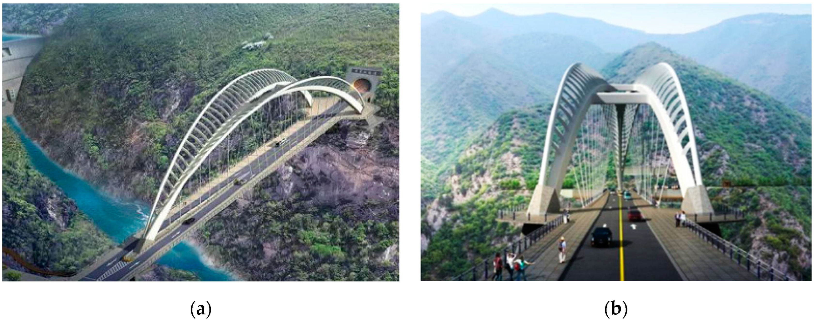
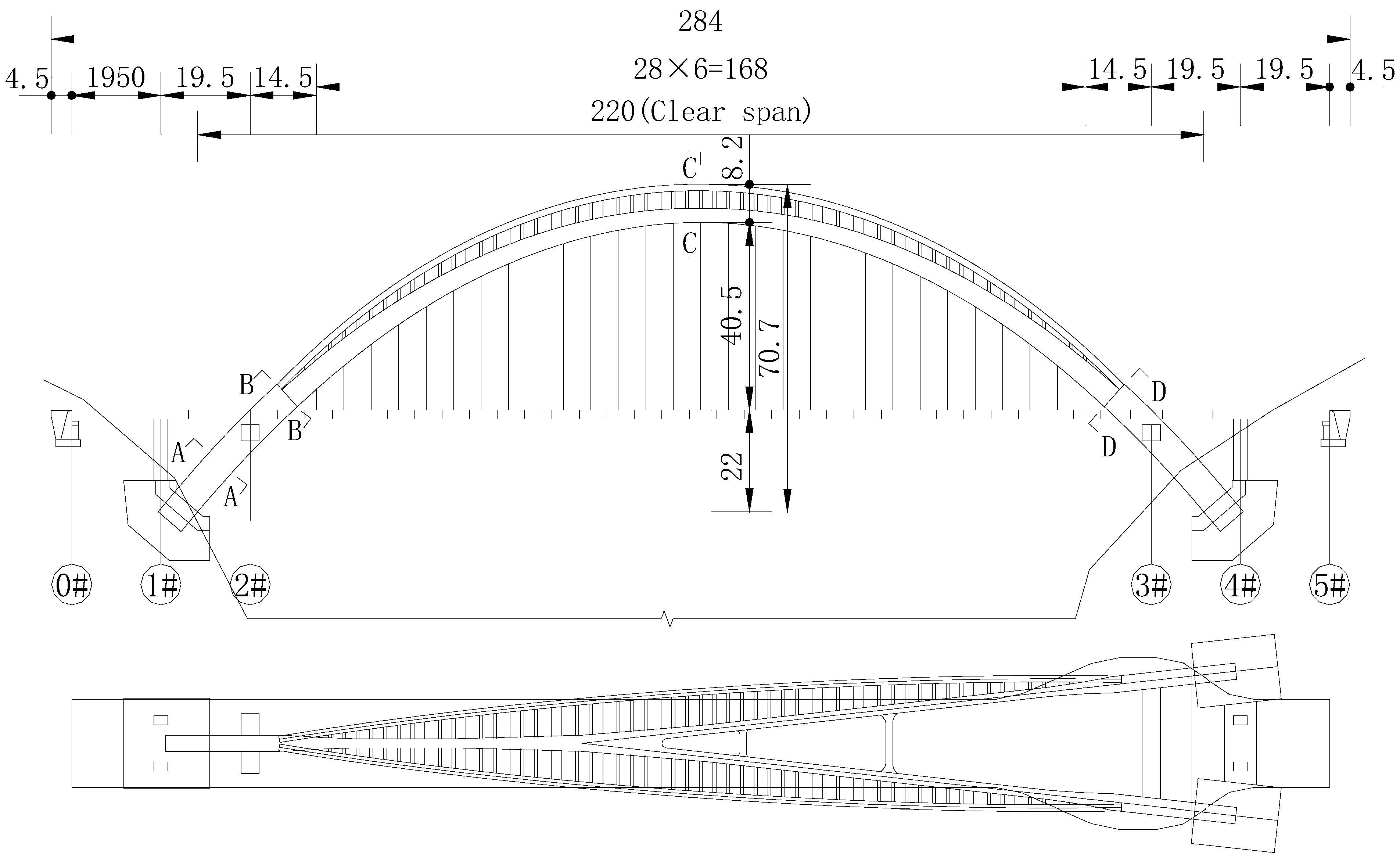
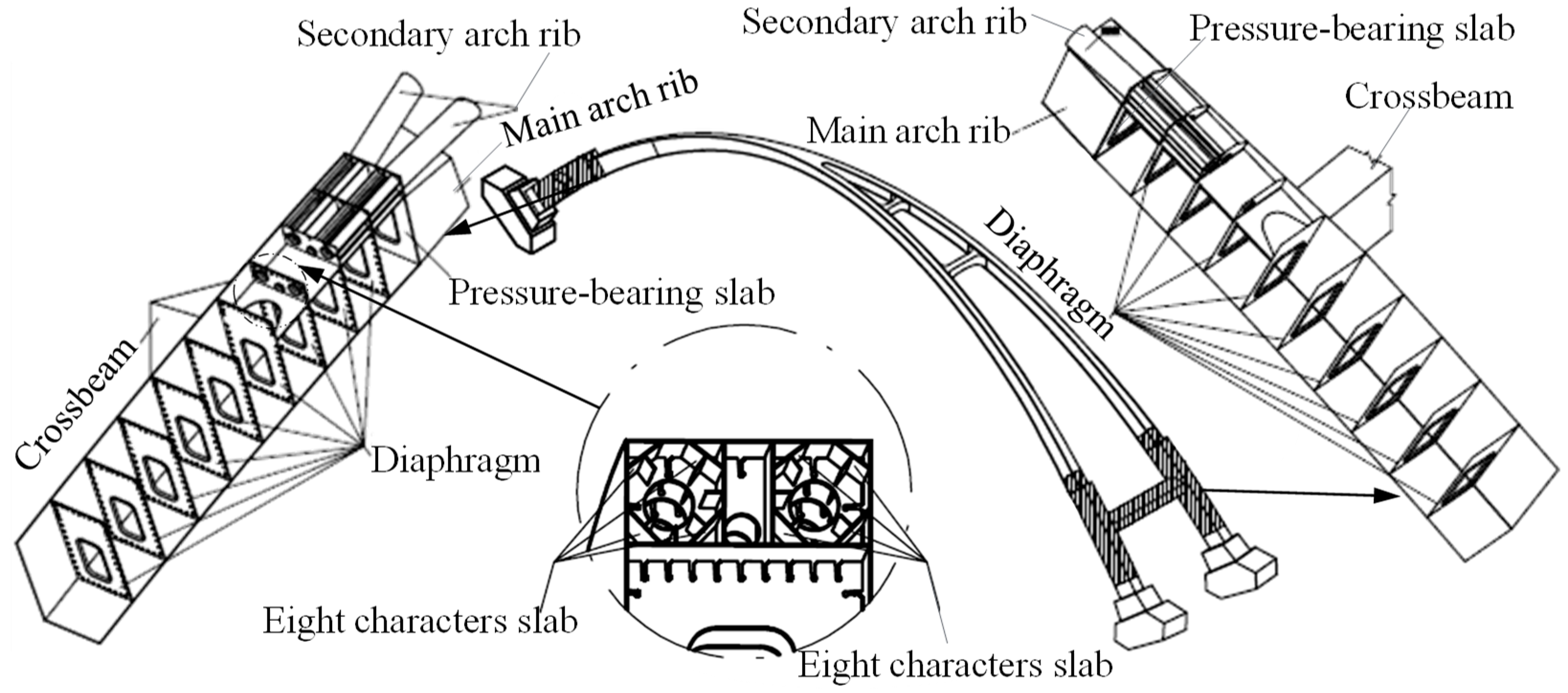
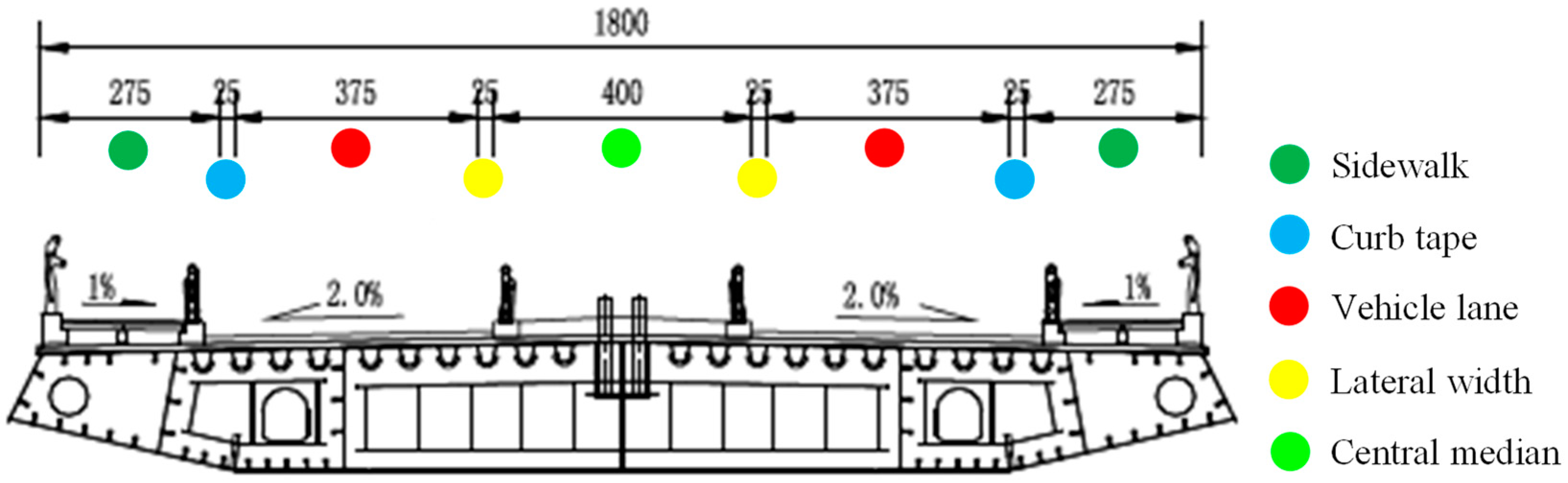
2.1. Target Bridge

Jinghe Bridge is an essential node project in the external transportation project of Dongzhuang Water Conservancy Hub, an outstanding attraction project in the tourism belt of Guanzhong Canyon and a special large-scale landscape bridge [31]. The construction of Jinghe Bridge can enable more convenient transportation between tourist attractions in the region, improve the tourism environment and enhance the speed of travel for tourists, which will drive and promote the further development of tourism in the project area. The three-dimensional space effect of the bridge is shown in Figure 1. The right bank of Jinghe Bridge is directly connected to the external traffic T-intersection, and the left bank is connected to the tunnel in a straight line. The special-shaped arch bridge, in order to pursue the landscape effect echoing with Dongzhuang Water Reservoir, not only is beautiful and unique, but also adopts the combination form of separated main arch ribs and secondary arch ribs to form the space-shaped structure, which further obtains a better visual effect.

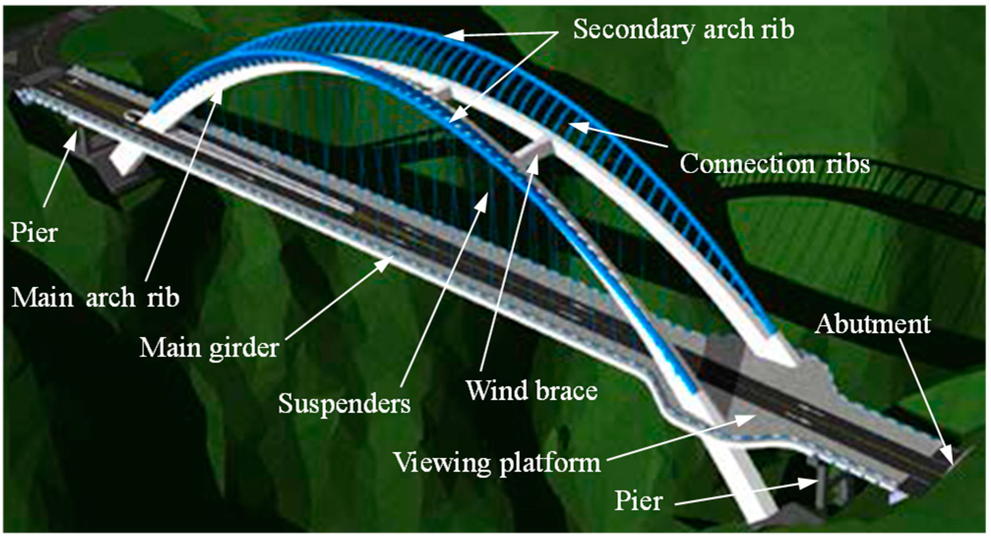
2.2. Innovative Design Concepts

The Jinghe Bridge is designed with the basic principles of regional, cultural and integrated characteristics and with the design concept of “showing the humanistic characteristics of the region and depicting a beautiful picture of the future of the region”. The starting point for the bridge landscape design is “harmonization with the hub and the surrounding environment”. Since both banks of the bridge are steep slopes, the river is relatively narrow and the design elevation of the bridge deck is relatively higher. Therefore, in order to avoid the bridge form tending to be conventional, to better coordinate the height of the mountains on both sides of the river, and to echo the plane curve of the hyperbolic arch dam, so that the bridge form and the environment can achieve coordination and balance in the configuration, a pioneering innovation was made to the main arch rib. The traditional single main arch rib design is abandoned, and the structural characteristics of butterfly arch bridge and medium-bearing arch bridge are mixed, adopting the medium-bearing space Y-shaped combined steel box arch. The arch ring and arch seats are divided into a single arch segment and a double arch segment, the arch ring is Y-shaped in space, and the arch ribs are separated into two pieces along the bridge, from single to double, from simple to complex, and from complex to simple, combining complexity and simplicity, which not only enables the shape of the arch to be more in the contemporary sense and three-dimensional sense of space, but also solves the traffic organization problem of T-shaped intersection.
The main and secondary arch collaboration Y-shaped arch bridge is an innovative arch bridge type, and the construction of this unique shaped arch bridge is the first of its kind in China. The imagery of the Y-shaped form is “Jinghe String Moon”. The overall shape of the structure is very dynamic and tense. The rounded three-dimensional arcs on the outside of the arch ribs emphasize the landscape theme of “Jinghe String Moon” and convey the spirit of innovation and progress, and the arch rib shape resembling a sail and a rainbow expresses the symbolic meaning of auspiciousness. The main and secondary arch collaboration Y-shaped arch bridge not only has a unique and beautiful shape, excellent landscape effect, favorable traffic visibility, and safe and reliable passage, but also can be applied to various terrain conditions, while reducing the number of arch ribs so that the economic performance is outstanding. In addition, in the new mode of single–double combination, the main and secondary arches are synergistically bearing, which also enables the structure to obtain better mechanical properties, and the triangular structure of the arch ribs from single to double increases the structural stability performance.
The main and secondary arch collaborative Y-shape thin-walled steel box arch bridge is mainly composed of main and secondary arch ribs, connecting ribs, suspenders, main girder, etc. The main components of the bridge are shown in Figure 2. The calculated span combination of the bridge is 2 × 19.5 m + 197 m (14.5 m + 28 × 6 m + 14.5 m) + 2 × 19.5 m, the main girder adopts double boxes and is a double-cell π-type steel box girder, the girder length is 274.7 m, the standard section width is 18.0 m, the main girder has a viewing platform at the intersection of double arches and main girder, the main girder width is 36.0 in the widened section and the girder height is 2.0 m [31]. The bridge layout is shown in Figure 3. The main arch adopts no hinge arch, the side and main span of the main girder use suspended continuous girder structure, and vertical bearings are set at the pier and crossbeam of the arch. The suspenders are flexible cables with a spacing of 6 m and a total of 29 pairs. Both ends of the suspenders are connected to the beam and the arch by steel anchor boxes, with tensioning at the arch end and anchoring at the beam end.

2.3. Design Features and Details
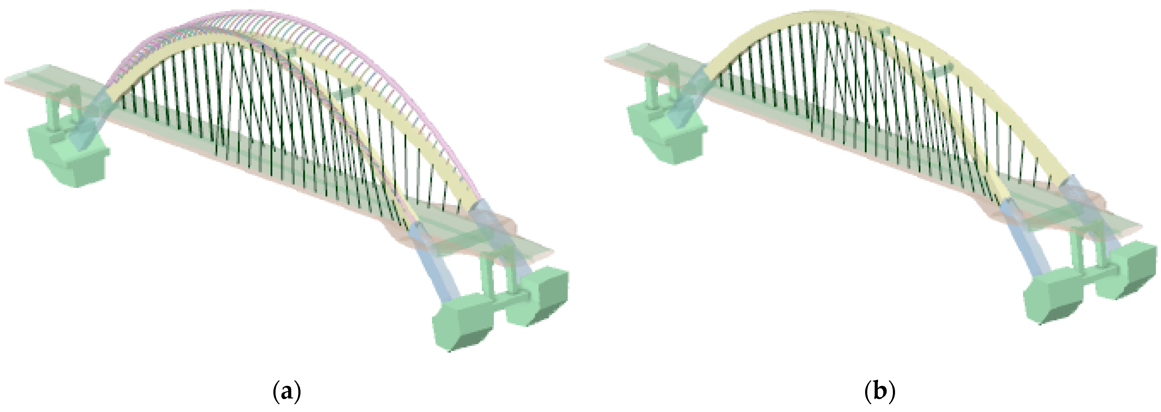
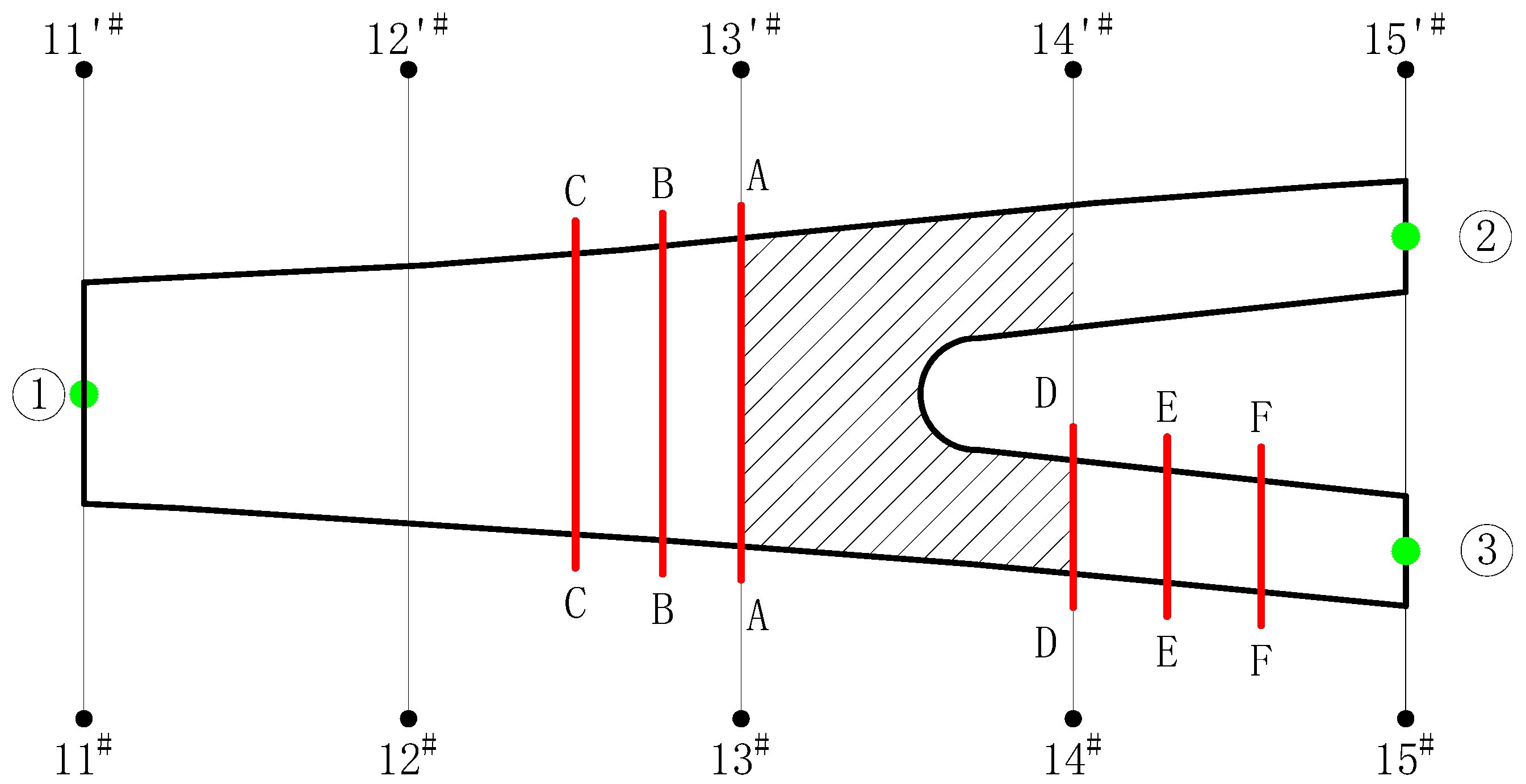
The main arch rib is a Y-shaped box arch with variable sections. The arch axis in the elevation adopts the suspension chain line, in which the net span is 220 m, the net height is 62.5 m, the arch axis coefficient is 1.347 and the height-to-span ratio is 1/3.52. The plane projection of the arch axis is Y-shaped, the single arch is arranged on the right bank side of Jinghe River, the double arch is arranged on the left bank side of Jinghe River and the angle of axis divergence is 12.42°. The arch box section is 3.0–6.6 m high and 2.0–3.5 m wide along the top of the arch to the foot of the arch. The arch box top slab, bottom slab and web are designed with variable thickness from the top to the foot of the arch, the slab thickness is 16–30 mm. The stiffening ribs and diaphragms are set to enhance the stiffness of the arch ribs, with a diaphragm spacing of about 1.5 m and a slab thickness of 12–24 mm, as shown in Figure 4. The bridge has two wind braces between the double main arches, with a rectangular steel box section, equal height with the arch ribs, and slab thickness of 20 mm. The bridge is designed with a crossbeam at the intersection of the arch ribs and the main girder on each bank, and the main girder is supported by supports. The crossbeam on the right bank arch adopts a variable-height rectangular steel box section with a section size of 4.0 m × 3.5–2.5 m. The crossbeam on the left bank arch adopts an equal-height rectangular steel box section with a section size of 4.0 m × 3.5 m.
The wall thickness of the steel box at the foot of the arch is relatively thin, and the steel box section is prone to distortion and out-of-plane deformation under the action of constant load and live load, so the setting of bearing slabs and diaphragms and stiffening ribs can effectively prevent excessive deformation of the section and improve the torsional deformation resistance of the thin-walled arch box. The single arch rib in the arch foot position sets longitudinal diaphragms, which consist of eight character slabs, as shown in Figure 5.
The secondary arch ribs are symmetrically arranged and inclined 5° outward around the line of their axes, which is a three-dimensional structure in space. The setting of secondary arch ribs improves the aesthetic characteristics of the structure. When the secondary arch ribs are removed, the distance between the top of the arch and the bridge deck is reduced and the arch becomes flat, which greatly weakens the structural aesthetics (see Figure 6). The arch axis is a suspended chain line, in which the net span is 184.5 m, the net height is 43 m, the height-to-span ratio is 1/4.29 and the arch axis coefficient is 1.756. The secondary arch is made of a circular steel tube section with 1.4 m diameter and 24 mm slab thickness. The stiffening ribs are slab ribs with a thickness of 12 mm, and the diaphragm is 12 mm thick. The axis of the main and secondary arch connecting ribs is a circular curve, varying step by step, with the section size of 0.7 m × 1.0 m and slab thickness of 20 mm.
In the Jinghe Bridge section layout, to meet the requirements of connecting the roadbed and tunnel, as well as because the Jinghe Bridge is part of an important landscape of the Guanzhong Canyon tourism belt, the deployment of sidewalks is considered for sections on both sides. The Jinghe Bridge standard section width is 18 m, using two lanes in both directions. The width of the lane is 2 × 3.75 m, and there are 2.75 m wide sidewalks on each side. The right bank of the bridge is connected to the T intersection; in order to increase the turning radius of the traffic lane, the central median is set up. The left bank is connected to the tunnel, the central median is canceled and the traffic lane and the tunnel are arranged in a straight line of equal width (see Figure 7).
The main girder is designed with a 0.5 m wind spout on each side, and the full width is 19 m. The thickness of the top slab is 16 mm, the stiffening ribs are U ribs and slab ribs, the thickness of the bottom slab at the span is 16 mm, the thickness at the supporting point is 24 mm and the stiffening ribs are slab ribs. The width of both side boxes is 5.2 m, with single box and double cells; the thickness of the web is 16 mm, and the stiffening ribs are slab ribs. The middle longitudinal girder is an I-shaped section with a 24 mm thick web and a 600 mm wide and 24 mm thick bottom flange. The crossbeam spacing is 3 m in the standard segment, and the crossbeams near the supporting point are arranged with a spacing of 0.6 m. The crossbeam height is 2 m, the thickness of the crossbeam at the supporting point is 24 mm, the thickness of the other crossbeams is 16 mm, and the crossbeams of each box are opened with manholes, as shown in Figure 7. The longitudinal length of the widened section of the viewing platform is 56.53 m, the platform extends 9 m, the top width is 36 m, the total width is 37 m and the outer edge varies along the curve.

3. Numerical Model

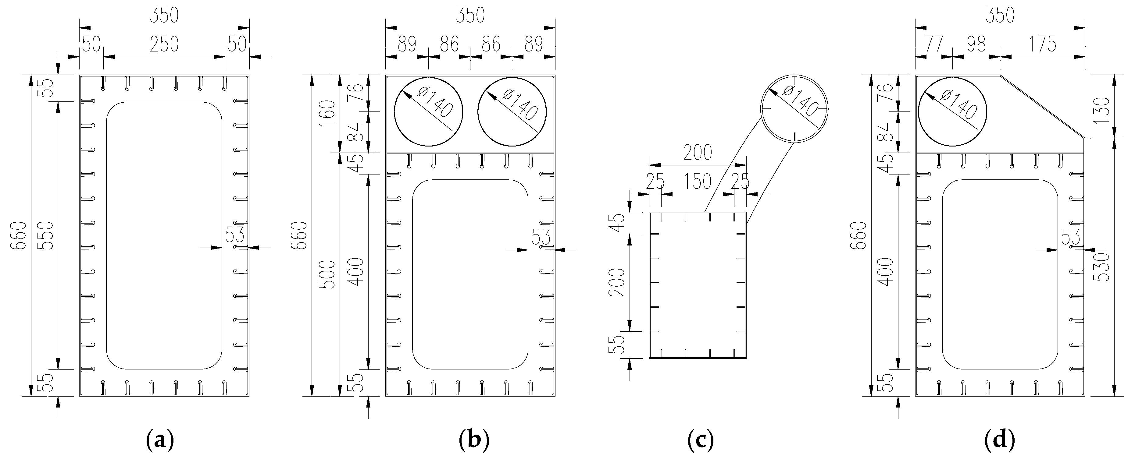
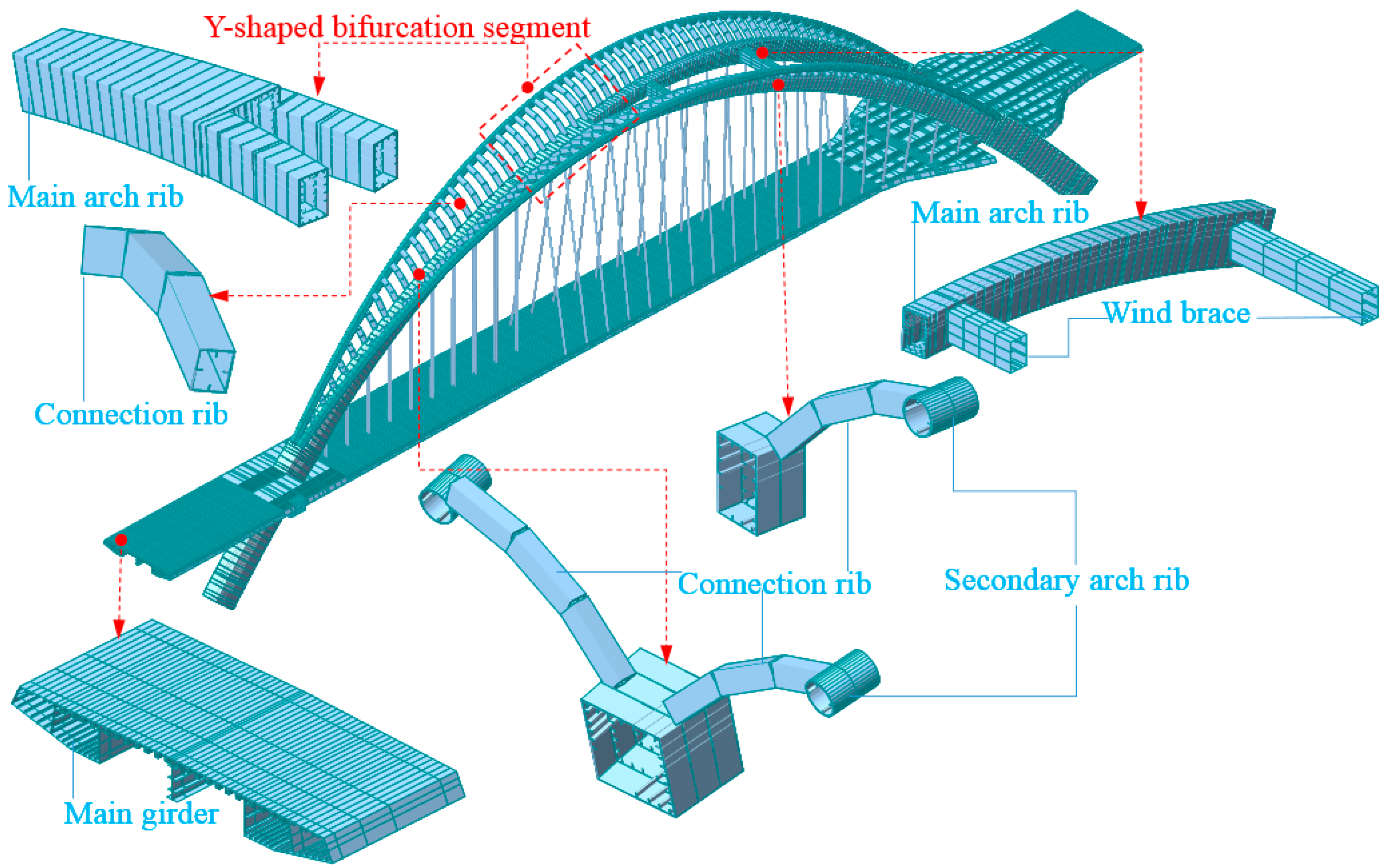
3.1. Establishment of Numerical Model

There are no drawings of completed bridges to be referenced for the innovative design of the Jinghe Bridge, so the innovative design of the bridge structure needs to be verified and analyzed. The bridge structure form is relatively complex, and the finite element method has the advantage of efficient and accurate calculation, so it is widely used in bridge calculation.
The bridge was analyzed by numerical analysis software MIDAS/CIVIL for overall structural static and dynamic analysis, and the bridge structure was simulated by spatial beam units. The numerical model of this bridge is shown in Figure 8. This model mainly controls the strength design, stress design and stiffness design of the structure. The internal forces and stress change during the assembling process of arch ribs are not considered in the model, so the analysis starts from the bridge completion stage. The coordinate system is chosen as a Cartesian coordinate system, and the direction along the bridge is defined as the X-axis direction, the transverse direction of the bridge is defined as the Y-axis direction and the direction of gravitational acceleration is defined as the Z-axis direction. The symbols of the analysis results are defined as follows: displacement is positive when it points to the same direction as the overall coordinate system, stress is positive when it is in tension, axial force is positive when it is in tension, and the positive and negative signs of bending moment are determined by the right-handed spiral criterion.
The main arch rib, secondary arch rib, connecting rib and crossbeam are simulated by beam units, the suspenders are simulated by truss units, the main girder is simulated by a single girder; there are 1590 nodes, 1434 beam units and 58 truss units in the whole bridge. The average unit size of the main arch rib is 1 m. The average unit size of the secondary arch ribs is 1 m. The average unit size of connection ribs is 0.6 m. The average unit size of the main girder is 1.25 m. The average unit size of the wind brace is 1.4 m. Each suspender is a single unit. In order to make unit stiffness and density correspond to actual engineering, stiffening ribs and diaphragms of arch ribs and the main girder are considered in unit sections.
A longitudinal floating system was adopted for the bridge, and super-high-damping rubber (SHDR) bearings were adopted as bearings. Super-high-damping rubber (SHDR) bearings have the advantages of the excellent effect of seismic isolation and strong dissipation of seismic energy, so SHDR bearings were selected for the bridge. According to the bearing carrying capacity requirements, two types of bearings were selected, namely SHDR620 × 620 × 223 and SHDR770 × 770 × 256. The SHDR bearings in the finite element model are simulated by elastic connection, and the mechanical property parameters of the SHDR bearings are shown in Table 2. The connection between the arch ribs and the earth’s rigid body is simulated by using general nodal support. The calculation method is the finite element method, and the analysis type is linear static analysis.

3.2. Material Parameters

The main structure is made of Q420qDNH weathering steel with a yield ratio of not more than 0.85 and a thickness of 4 mm to 50 mm; the mechanical property parameters of Q420qDNH weathering steel are shown in Table 3. The steel of the auxiliary structure is Q235B, with a thickness of 10 mm to 45 mm, and the mechanical property parameters of Q235B steel are shown in Table 4. The structures in Figure 8 are main structures, other structures are auxiliary structures, such as guardrails. Three specifications of epoxy-coated PES7 series steel wire cables are used for the arch suspenders: PES7-73 for 1#(1′#) suspender, PES7-61 for 2#(2′#) to 3#(3′#) suspenders, and PES7-55 for 4#(4′#) to 29#(29′#) suspenders. PES refers to polyethylene high-strength steel cable; 7 refers to the wire diameter of 7 mm; and 73, 61 and 55 refer to the number of wire roots. The physical property parameters of the steel and suspender are shown in Table 5.

4. Numerical Verification of Innovative Designs

4.1. Load-Carrying Capacity

The purpose of this bridge load-carrying capacity analysis is to check whether the strength and stiffness of the structure meet the design requirements in service condition. The calculated loads of the Jinghe Bridge mainly include permanent action and variable action. The permanent actions include first stage constant load, second stage constant load and suspender force. The permanent action and variable action shall conform to the regulations of the current specification [32]. The first stage of constant load mainly considers the self-weight of the structure. Self-weight load is calculated by multiplying the cross-sectional area of the elements by the gravitational density of the material. The second stage constant load is distributed to the main girder according to uniformly distributed load, then transferred to the suspenders and finally to the arch ribs. The second stage of constant load includes bridge deck pavement, guardrail and pedestrian facilities, etc. The cast-in-place layer of the main girder adopts C50 steel fiber concrete with a thickness of 10 cm and weight of 26 kN/m3, and the load is calculated according to the actual load-bearing area. The bridge deck pavement layer is made of 10 cm thickness asphalt concrete with a weight of 24 kN/m3, and the load is calculated according to the actual area of load bearing. The pavement pillow beam and sidewalk slab are made of C30 concrete with a weight of 26 kN/m3, loaded according to the actual position. The sidewalk railing is steel railing, and the single side load is calculated according to 1.0 kN/m. The suspender force mainly refers to the initial tension of the suspender, which is included in the structural analysis according to the preload. Variable effects include foundation settlement effects, vehicle load and temperature effects. The foundation settlement effect is considered according to the main pier settlement for vertical down 1 cm, the two banks of the abutment settlement for vertical down 0.5 cm. The vehicle load level is highway I. According to the results of the structural nature vibration analysis, the structural basic frequency value is 0.53 Hz, and the resulting impact coefficient is 0.05. The load on the sidewalk is considered according to the crowd load of 2.5 kN/m2. The temperature effects are considered using the system temperature and gradient temperature functions of the software for the overall variable temperature and nonlinear temperature rise and fall, respectively.
The design of the limit state of carrying capacity of the main components is calculated according to the basic combination of action effects. The load-carrying capacity limit state calculation is carried out in accordance with article 4.2.1 of the specification [33]. Under the basic combination of action effects, the maximum tensile stress of the arch rib is 197 Mpa, as obtained from Figure 9a; the maximum tensile stress appears in the connecting rib at the end of the main arch, and the control load condition is the combination of constant load + vehicle load + overall temperature fall + foundation settlement load. The maximum compressive stress is 178 Mpa, which occurs at the position of 1/4 arch rib on the single arch side, and the control load condition is the combination of constant load + vehicle load + overall temperature fall + foundation settlement load. The maximum shear stress is 46 Mpa, and its control condition is the combination of constant load + vehicle load + crowd load + foundation settlement + cross wind load. According to the strength design value of steel in Table 3.2.1 of specification [33], the ultimate state stresses of steel structure carrying capacity are less than 320 Mpa and 185 Mpa, which meet the design requirements.
As shown in Figure 9b, the maximum tensile stress of the main girder is 59 Mpa, and its control load condition is the combination of constant load + vehicle load + overall temperature fall + foundation settlement load. The maximum compressive stress is 71 Mpa; the control load condition is the combination of constant load + vehicle load + crowd load + foundation settlement + cross wind load, and the maximum tensile and compressive stresses occur near 3/8 of the span of the main girder. The maximum shear stress is 30 Mpa, and its control load condition is the combination of constant load + car load + crowd load + foundation settlement + cross wind load. According to the strength design value of steel in Table 3.2.1 of specification [33], the ultimate state stresses of the steel structure carrying capacity are less than 320 Mpa and 185 Mpa, which meet the design requirements.
A conventional arch bridge suspender is symmetrically designed in the cross-bridge direction and longitudinal direction, so the suspender also carries the force symmetrically. However, the suspenders of special-shaped arch bridges are arranged heterogeneously in space, and the suspender forces are relatively complex. The suspender forces of the main and secondary arch collaborative Y-shaped thin-walled steel box arch bridge in the service stage are shown in Table 6, and the distribution trend of the suspender forces is gradually decreasing from the two ends of the bridge to the middle of the span. The suspender force is larger at both ends of the bridge; the maximum force appears at the short suspender 1#(1′#), 29#(29′#); the maximum force is 1468 kN; and the breaking force value of the suspender is 4972 kN. The safety factor is greater than 3.0, and therefore, the suspender model selection meets the design requirements. The suspenders 4#(4′#)–24#(24′#) in the middle of the span have a relatively uniform force of 876.3 kN, compared with the suspenders 11#(11′#)–29#(29′#) in the double arch rib segment, and the suspenders 1#(1′#)–10#(10′#) in the single arch rib segment have a slightly smaller force.

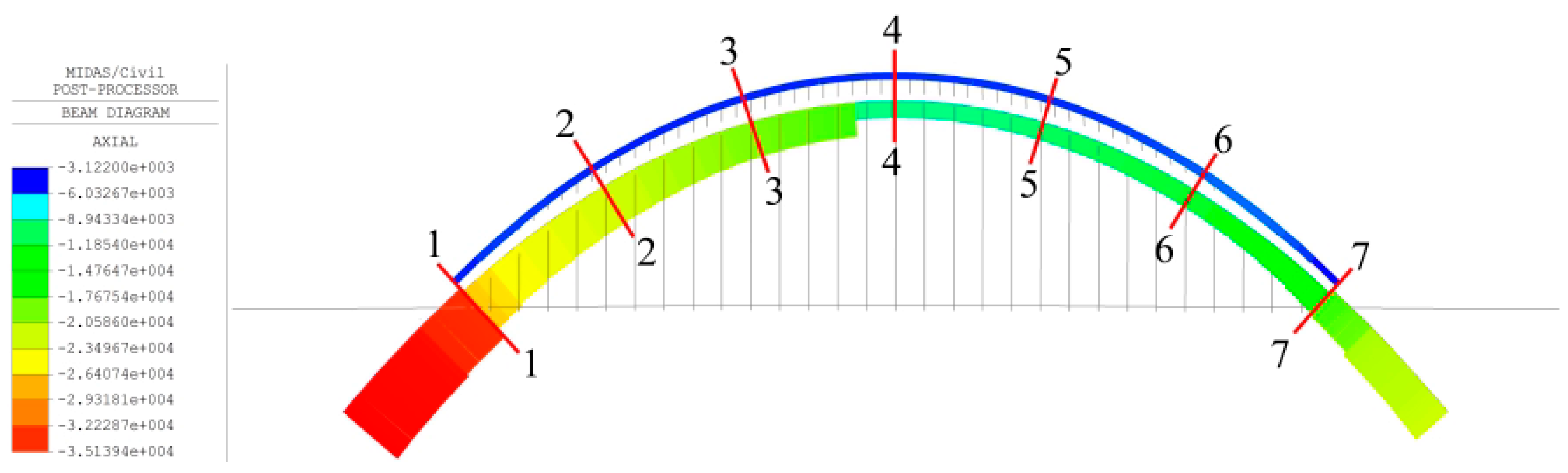
4.2. Axial Force Distribution of Main and Secondary Arch Ribs

From Figure 9a, it is easy to find that the stress in the main arch rib is much greater than that in the secondary arch rib at the same location, which indicates that the load is mainly carried by the main arch rib. The secondary arch ribs have the function of load sharing, not just landscape decoration. Due to the particularity of the main and secondary arch collaborative system and the thin-walled steel box arch ribs, in order to provide more reference information on the design details of the main and secondary arch collaborative steel box arch bridge, the axial force sharing between the main and secondary arch ribs at seven locations is studied, as shown in Figure 10.
Figure 10 shows the axial force diagram of the arch rib under constant load. The axial force of the arch rib is compressed in the axial direction as a whole. The axial forces of the main arch rib and the secondary arch rib are symmetrically distributed in the cross-bridge direction, and the transition is uniform along the arch axis. The axial force of the main arch rib is slightly larger on the single arch rib side than on the double arch rib side in general, and the axial force of the main arch rib increases suddenly near the foot of the arch, which is due to the main girder load in this area. The axial force of the main arch rib at the foot of the single arch side is the largest, with a maximum value of 35,139.4 kN. The secondary arch ribs have the maximum axial force at the top of the arch and the minimum axial force at the foot of the arch, but the axial force on all sections does not vary much, ranging from −3183.11 kN to −3571.70 kN. The results of the axial force calculations for the seven sections in Figure 10 are listed in Table 7, from which it can be seen that at these seven positions, the main arch ribs share approximately 70−88% of the axial force, while the secondary arch ribs also share 12−30%. The secondary arch ribs share a smaller percentage of the load on the single arch rib side than on the double arch rib side, which is consistent with the results observed from the combined load action (Figure 9), which indicates that the load sharing ratio between the main arch rib and the secondary arch rib is independent of the load type. The secondary arch ribs bear a certain proportion of the load with a small cross-sectional area, which not only plays the role of structural carrying capacity, but also meets the aesthetic needs of the landscape, so the synergistic effect of the collaborative system of main arch ribs and secondary arch ribs is outstanding and reasonably designed.

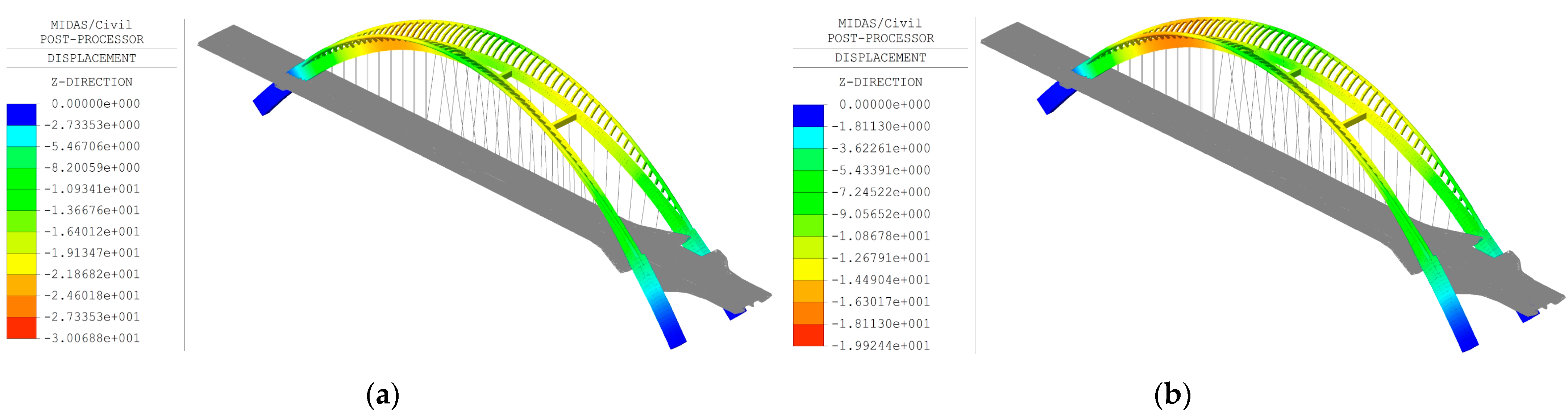
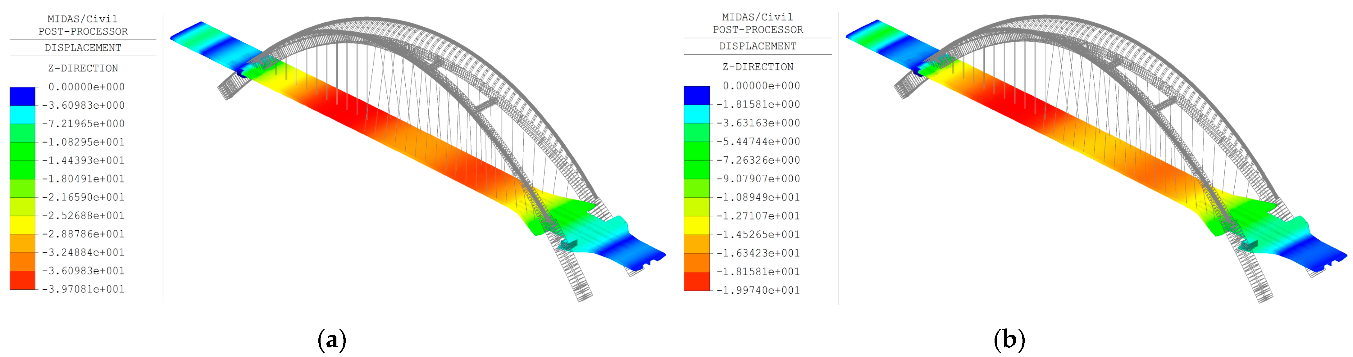
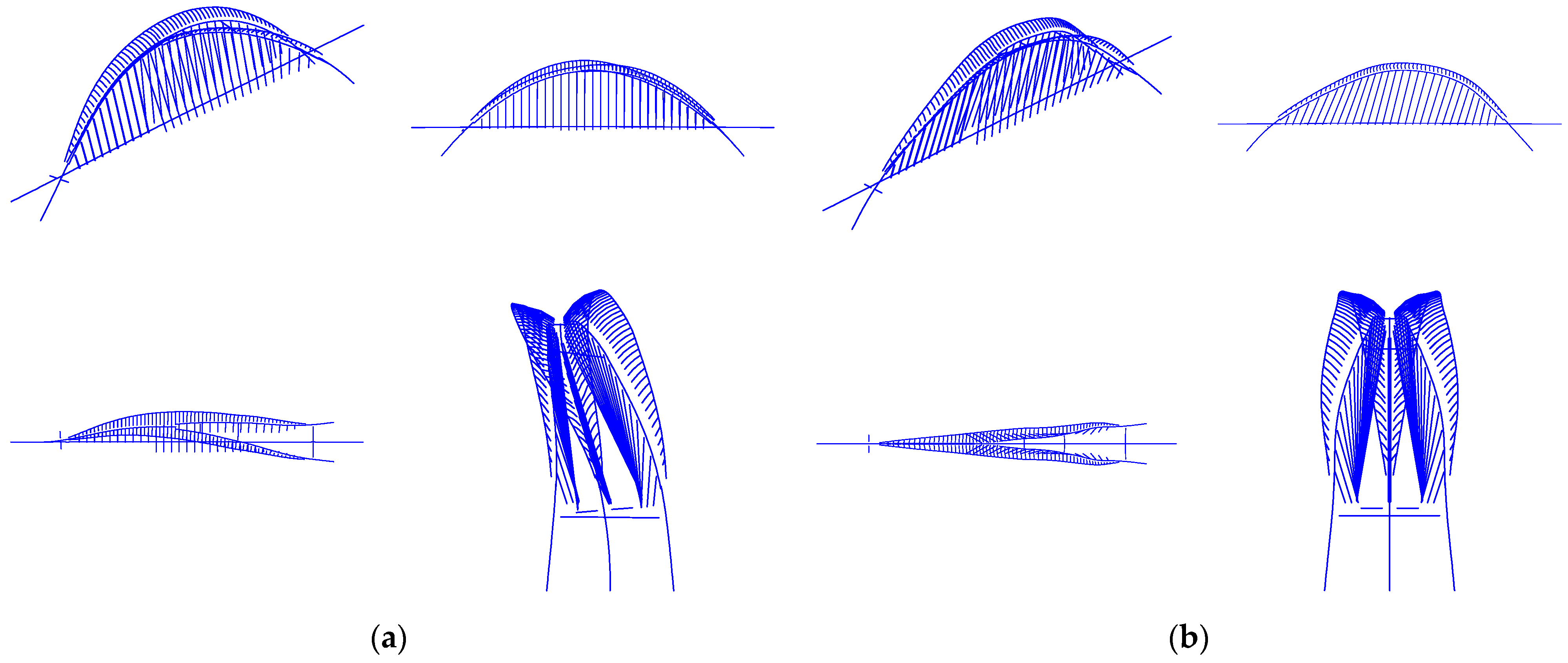
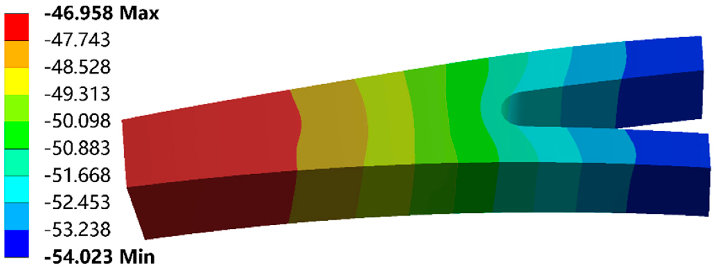
4.3. Deformation Analysis

In accordance with Article 4.2.3 of specification [33] and article 6.2.1 of specification [34], the maximum vertical deformation of the arch rib is not over L/1000 (“L” denotes the span) and the vertical deformation of the main girder is not over L/800 under the action of vehicle lane load (excluding impact force). Figure 11 and Figure 12 show the vertical displacements of the arch ribs and main girder, respectively.
From Figure 11, it can be seen that the maximum vertical displacement of the arch rib under the vehicle load is 30 mm and the transverse displacement is 4 mm; the maximum vertical displacement under the crowd load is 20 mm and the transverse displacement is 16 mm, which meets the design requirements. Figure 11 shows that the maximum vertical deformation of the arch rib is not in the middle of the span, but near 3 L/8 and 5 L/8, and the deformation trend is similar to the “W” shape because the arch rib structure is spatially Y-shaped. Figure 12 shows that the maximum deflection of the main girder is 40 mm under vehicle load and 20 mm under crowd load, which meets the design requirements. The effect of both vehicle and crowd loads acting together is combined by the combination factor required by specification.

4.4. Dynamic Characteristic Analysis

The main purpose of the dynamic analysis model of the bridge is to analyze the self-vibration frequency and period of the structure and control the overall stiffness. The main difference between the dynamic analysis model and the static analysis model is that the dynamic model adds mass data. What plays a decisive role in the dynamic analysis is generally the first few orders of self-vibration frequency and mode. The first six orders of self-vibration characteristics of the structure calculated by MIDAS/CIVIL software using the subspace iterative method are shown in Table 8. The first-order frequency of the structure is 0.53 Hz, and the human sense frequency range is 2.5–3.5 Hz; the structure frequency is not in the human sense frequency range, and the frequency distribution of each order is relatively reasonable.
The vibration modes reflect the influence of boundary constraints and component stiffness on the vibration condition, and the vibration modes of the first six orders of the structure are shown in Figure 13. Figure 13 shows that the first four orders of arch rib mode are mainly flexural vibration, and the fifth order mode has bending and twisting vibration; the frequency of bending and torsional vibration, 0.95, is 1.79 times the first order of flexural vibration frequency of 0.53, which indicates that the anti-bending and torsional stability performance of the main and secondary arch collaborative Y-shaped thin-walled steel box arch bridge is better than the anti-flexural stability performance. In the first six orders of modes, the main girder modes are all deflection and drift, and no torsional vibration occurs, indicating that the main girder has good stability performance against torsion. In the high-order formation, the deflection vibration of the main girder no longer occurs alone, and the deflection vibration of the main girder occurs simultaneously with the deflection vibration of the arch ribs. The reason for the simultaneous vibration of the main girder and the arch ribs is the connecting force transmission effect of the suspenders. Structural mode is mainly manifested as flexure and drift, and special attention should be paid to flexural vibration in the design. The torsional stability of the structure is rather good, mainly due to the stable tetrahedral structure formed by the three bifurcated arch ribs, the contribution of the secondary arch ribs and connecting ribs to increasing the torsional stiffness, the wind bracing and crossbeams between the double arch ribs increasing the torsional stiffness of the structure, and the asymmetry of the distribution angle of the suspenders between the main girder and the main arch rib increasing the torsional stability.

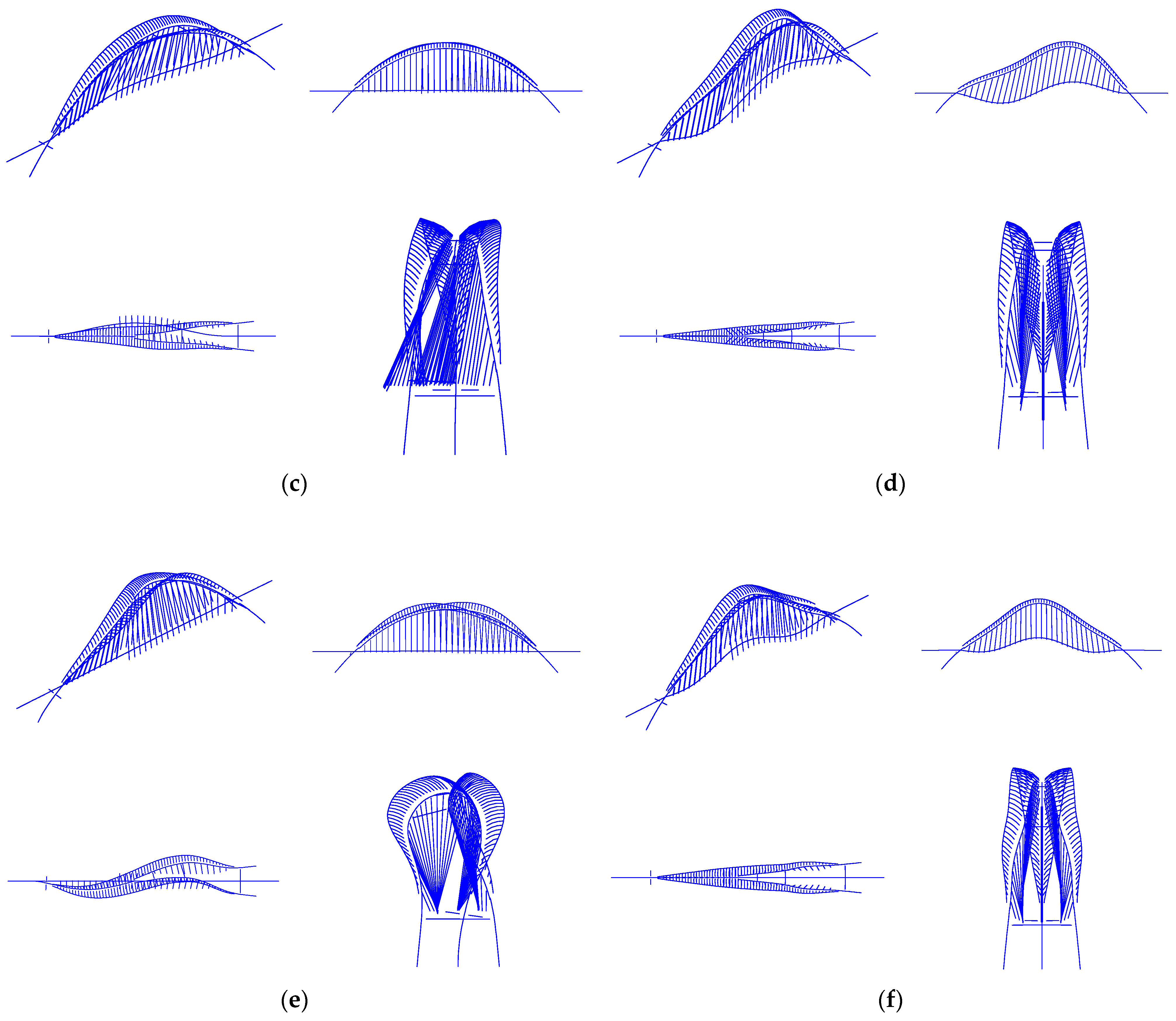
5. Bifurcation Segment Shear Lag Effect and Stress Distribution

From Figure 2, it can be seen that the unconventional thin-walled steel box arch ribs are bifurcated from single arch rib to double arch ribs near the top of the arch, and the cross-sectional dimensions of the arch box are changed, but the arch boxes are all single box and single cell, which is an innovative design. For such an innovative design, the shear lag effect of the thin-walled steel box arch ribs has a detrimental effect on the structure, not only with uneven stress distribution, but also with the problem of warping instability of the thin plate. Therefore, the finite element analysis method is adopted to study (1) the shear lag effect of this unconventional thin-walled steel box arch rib and (2) the stress distribution characteristics and mechanical details of the arch rib bifurcation section.
The arch rib is a three-dimensional structure with complex constructions and high accuracy requirements for mechanical calculations. A high-precision three-dimensional spatial model should be established to ensure that the spatial geometry of the structure matches the design as much as possible. As shown in Figure 14, the local finite element model was established by taking out the single to double bifurcation segment of the arch ribs from the global beam unit model, and the local finite element model was established by using ANSYS Workbench. The thin-walled arch box and the diaphragm in the local model are simulated by using the shell unit. Considering the boundary effect influence, the local model is four suspenders with a spacing of 6 m in length. The boundary constraints of the local model are applied at points ①–③ in Figure 14, which represent the boundary conditions of single and double arch ribs, respectively. The correct boundary constraints are essential for the analysis of the local model. where the beam unit model has a single node in the cross-section and the shell unit local model has multiple nodes in the cross-section. Therefore, in order to keep the boundary conditions on the model built using the shell unit consistent with the beam unit, the rigid coupling of single and multiple nodes will be performed on the section ①–③ as in Figure 15 through the rigid field, where the nodal forces and nodal displacements extracted from the cross-section in the global model of the beam unit are applied at the single node. Suspender forces extracted from the global model of the beam unit are applied at 11#(11′#)–15#(15′#) to accurately simulate the boundary constraints.

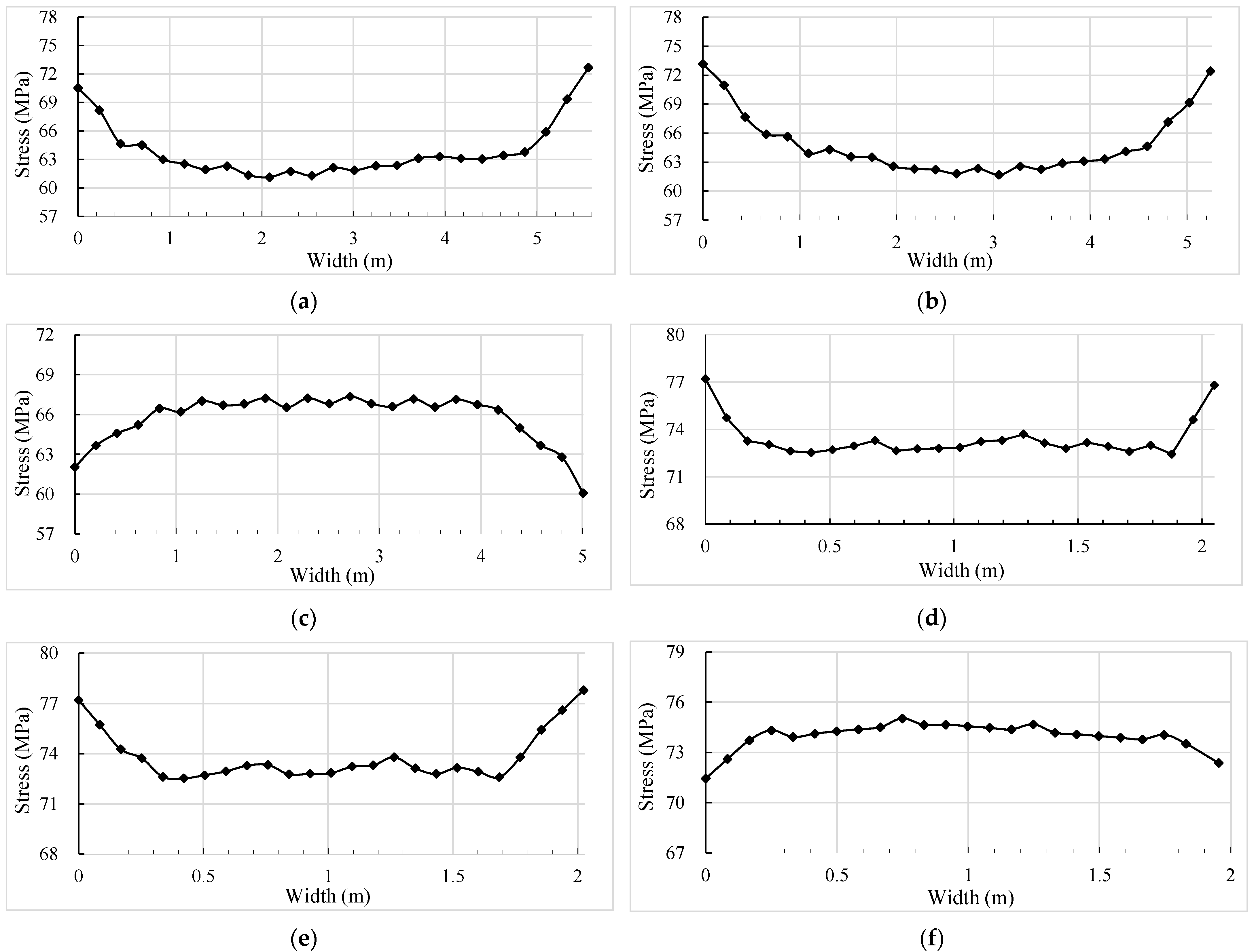
5.1. Analysis of Shear Lag Effect

Although there are already formulas to consider the shear lag effect of a thin-walled concrete box girder, these formulas are not applicable to thin-walled steel box arch ribs due to the special characteristics of thin-walled steel box arch ribs, and thus the finite element method still has the advantage of a fast and accurate analysis of the shear lag effect. Six typical cross-sections in Figure 14 are selected to study the shear lag effect of thin-walled steel box arch ribs: cross-section A-A is the location of the suspender-anchored diaphragm on the side of the single arch rib, cross-section B-B is the location of the A-type diaphragm on the side of the single arch rib, cross-section C-C is the location of the B-type diaphragm on the side of the single arch rib, cross-section D-D is the location of the suspender-anchored diaphragm on the side of the double arch ribs, cross-section E-E is the location of the A-type diaphragm on the side of the double arch ribs, and cross-section F-F is the location of the B-type diaphragm on the side of the double arch ribs. Figure 15c,d respectively show the A-type diaphragm and B-type diaphragm. The a-type diaphragm is a hollow diaphragm on the complete section of the arch rib. The B-type diaphragm is not a complete one, but only half of the diaphragm.
Under the action of symmetrical vertical forces, the positive stresses on the flange of the box girder are unevenly distributed along the section width direction. This phenomenon of uneven distribution of positive stresses along the width of the flange due to the lag in the transfer of shear forces from the web to the flange is called the “shear lag effect”, which is usually measured by the shear lag coefficient, defined as
λ = σ/σ0,
where λ represents the shear lag coefficient, σ represents the actual positive stress in the section, and σ0 represents the positive stress in the section calculated according to the elementary beam theory; when σ > 1, it is called “positive shear lag”, and when σ < 1, it is called “negative shear lag”.
In bridge design, constant load, live load and preload all produce shear lag effects in the cross-section, but constant load is predominant. Figure 16 shows the distribution of axial compressive stresses in six typical sections of thin-walled steel box arch ribs under constant load, with the horizontal axis representing the transverse width of the steel box arch ribs in the figure. The positive shear lag effect occurs in sections A-A, B-B, D-D and E-E, and the negative shear lag effect occurs in sections C-C and F-F. Sections C-C and F-F are the locations where the B-type diaphragm is located, and the B-type diaphragm is not a complete one, but only half of the diaphragm; therefore, a significant shear lag effect is observed in both locations, complete and incomplete diaphragms. Sections A-A, B-B and C-C are located in the single arch rib with a wider arch box cross-section, while sections D-D, E-E and F-F are located in the double arch ribs with smaller arch box cross-section width; therefore, the shear lag effect observed in the single arch rib is more obvious than that in the double arch ribs, and the maximum shear lag coefficient is 1.24. The width of the thin-walled arch box with double arch ribs is only 2 m, and the shear lag effect is not obvious; in particular, the negative shear lag coefficient is relatively small. The curve fold in Figure 16 is the sudden change in stress caused by the longitudinal stiffening rib. The shear lag effect was also observed in the bottom slab for the thin-walled steel box arch ribs, and the distribution regularity is similar to that of the top slab, which is not repeated here.
The actual axial compressive stresses σ occurring at the web on the arch rib section extracted from Figure 16 are listed in Table 9. The axial compressive stresses σ0 calculated according to the primary beam theory are read from the overall model of the beam unit, which is uniformly and equivalently distributed over the arch rib section, and the values are all listed in Table 9. The shear lag coefficient λ calculated according to Equation (1) is presented in Table 9, and the maximum shear lag coefficient is 1.24.

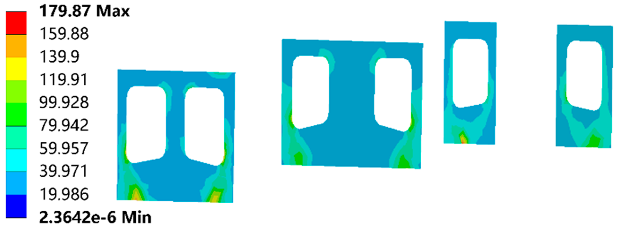
5.2. Stress Distribution Analysis of Single and Double Arch Rib Bifurcation Segment

Figure 17 shows the vertical deformation of the local model. The vertical deformation trend is overall consistent with the global model established using the beam unit, but the vertical deformation on the same section appears to be unevenly distributed, and the section shows a regularity of larger displacement on both sides and smaller displacement in the middle, but this pattern is not obvious. The stress distribution on the bifurcated section of the whole arch rib is relatively uniform, and it is worth paying attention to the stress distribution state of the diaphragm in the anchorage area. Figure 18 shows the von Mises stresses in the diaphragm at the anchorage area under constant load in the 24 m local model, which is between 39 MPa and 77 MPa in most of the range, with only a local stress concentration at the location where the suspender is in contact with the diaphragm, with a maximum stress of 179.87 MPa. The arch rib bifurcation segment has the same distribution regularity under vehicle load or combined load. The von Mises stresses of the bifurcated segment model are analyzed under the five most significant design load combinations, which are (1) constant load + vehicle load + foundation settlement load, (2) constant load + vehicle load + overall temperature rise + foundation settlement load, (3) constant load + vehicle load + overall temperature fall + foundation settlement load, (4) constant load + vehicle load + crowd load + overall temperature rise + foundation settlement load and (5) constant load + vehicle load + crowd load + overall temperature fall + foundation settlement load.
Table 10 lists the von Mises stress variation ranges for the top slab, bottom slab and web of the bifurcated segment of the arch ribs. The von Mises stress of the bifurcated segment of the arch rib is mainly the distribution density of the combination of the axial force and bending moment of the arch rib in the cross-section, and the difference between the stresses of the single and double arch ribs is slight, but in general the stress of the double arch ribs is higher than that of the single arch rib. Under the action of load combinations (1)–(5), the stresses in the top slab, bottom slab and web of single and double arch ribs are all between 0 and 197 MPa, which are all less than the allowable stress of 320 MPa. Although there are local stress concentrations in the diaphragm in the anchorage area, the stress concentration range is small, which means that the current design of single and double bifurcation of arch ribs is reasonable. Noticeable shear lag effects were also observed on the top and bottom slabs of the thin-walled steel box arch ribs under the load combination, with a maximum shear lag coefficient of 1.4. The stresses in the arch ribs considering the shear lag effect have not exceeded the allowable stresses, and the installation of stiffening ribs and diaphragms reduces the probability of local instability of the thin-walled arch box due to the shear lag effect.

6. Conclusions

In accordance with the bridge location environment and functional requirements of the Jinghe Bridge, a new structural form of single and double combination of arch ribs and collaborative working of the main and secondary arches was proposed for the first time, and the innovative design details and mechanical behavior of the main and secondary arch collaborative Y-shaped thin-walled steel box arch bridge were studied. The significant conclusions obtained are as follows:
  • The innovative design concept and design details have been discussed and verified by numerical calculations, showing that the structure meets the design requirements in terms of mechanical performance and has certain advantages in terms of static stability.
  • The traditional single arch rib design is mechanically and aesthetically slightly worse than the main and secondary arch collaborative system. The secondary arch rib bears a certain proportion of the load with a smaller cross-sectional area, which not only plays the role of structural bearing, but also meets the aesthetic needs of the landscape; therefore, the synergistic effect of the main and secondary arch rib collaborative system is outstanding and reasonably designed.
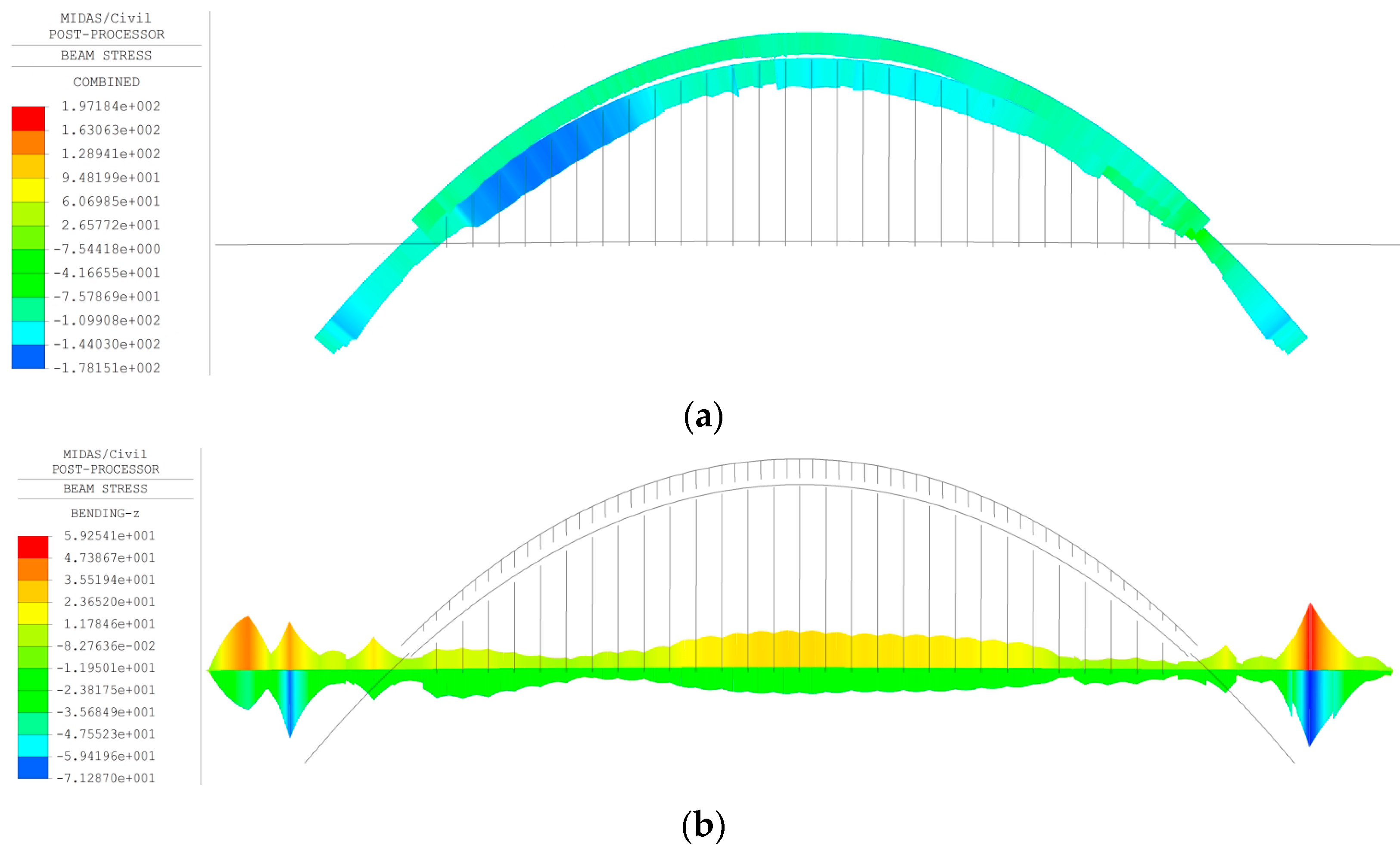
  • The maximum tensile and compressive stresses in the main girder all occur at 3/8 of the span; the maximum tensile stress in the arch ribs occurs at the main arch end of the main and sub-arch connecting ribs, and the maximum compressive stress occurs at the position of 1/4 arch rib on the single arch side.
  • As the shape of the arch rib is spatially Y-shaped, the vertical deformation of the structure is special, and the maximum vertical deformation of the arch rib is not in the middle of the span, but in the vicinity of 3 L/8 and 5 L/8, and the deformation trend is similar to a “W” shape.
  • The structural mode is mainly manifested as deflection and drift, and special attention should be paid to the deflection vibration problem in the design. The relatively good torsional stability performance of the structure is mainly due to the innovative design of the three-part bifurcated arch ribs and the stiffness contribution of the secondary arch ribs and connecting ribs, and these design measures can be referred to by future bridge designs.
  • The shear lag effect was observed in any cross-section of unconventional thin-walled steel box arch ribs, and the shear lag effect was more noticeable in single arch ribs than double arch ribs. The shear lag coefficient decreased with the decrease in arch rib width, and the maximum shear lag coefficient was 1.4 under the design load combination.
  • In future bridge construction, the main and secondary arch collaborative Y-shaped steel box arch design may be widely used in urban landscape bridges, and the design concept and method presented in this paper may provide an effective reference for the construction of similar projects in the future.

Author Contributions

Conceptualization, Q.H. and X.W.; methodology, Q.H.; software, Q.H.; validation, Q.H., X.W. and H.W.; formal analysis, Q.H. and X.W.; data curation, Q.H., H.W. and Q.C.; writing—original draft preparation, Q.H.; writing—review and editing, Q.H. and X.W.; project administration, X.W.; funding acquisition, H.W. and Q.C. All authors have read and agreed to the published version of the manuscript.

Funding

This research was funded by Shaanxi Provincial Department of Transport Scientific Research Project (No. 21-62K).

Institutional Review Board Statement

Not applicable.

Informed Consent Statement

Not applicable.

Data Availability Statement

The analysis data used to support the findings of this study are included within the article.

Conflicts of Interest

The authors declare no conflict of interest.

References

  1. Zhou, X.; Zhang, X.G. Thoughts on the Development of Bridge Technology in China. Engineering 2019, 5, 1120–1130. [Google Scholar] [CrossRef]
  2. Chen, B.C.; Liu, J.P. Review of construction and technology development of arch bridges in the world. J. Traffic Transp. Eng. 2020, 20, 27–41. (In Chinese) [Google Scholar] [CrossRef]
  3. Liang, Y.; He, W.; Tang, M.L. State-of-the-art review of bridge aesthetics in 2019. J. Civ. Environ. Eng. 2020, 42, 213–222. [Google Scholar] [CrossRef]
  4. Kossakowski, P.G.; Wcislik, W. Fiber-Reinforced Polymer Composites in the Construction of Bridges: Opportunities, Problems and Challenges. Fibers 2022, 10, 37. [Google Scholar] [CrossRef]
  5. Ma, B.; Lin, Y.P.; Zhang, J.J.; Xu, Y. Decade Review: Bridge Type Selection and Challenges of Lupu Bridge. Struct. Eng. Int. 2013, 23, 317–322. [Google Scholar] [CrossRef]
  6. Qin, S.Q.; Hu, J.; Cao, H.Y.; Kang, J.T.; Pu, Q.H. Finite Element Model Updating of Large-span Arch Bridge Based on Experimental Data. China J. Highw. Transp. 2019, 32, 66–76. (In Chinese) [Google Scholar] [CrossRef]
  7. Wang, F. Comparison and Selection of Erection Scheme for Steel Box Basket Handle Arch or Xijiang River Bridge on Newly-Built Nanning-Guangzhou Railway. Bridge Constr. 2013, 43, 117–121. (In Chinese) [Google Scholar]
  8. Cheng, K.M.; Ketchum, M.A.; Drouillard, F. Nanning Butterfly Tied Arch Bridge Over the Yong River in China. Struct. Eng. Int. 2010, 20, 308–311. [Google Scholar] [CrossRef]
  9. Ni, Z. Key Techniques in the Fabrication Process of the Steel Structure for Lupu Bridge. China Railw. Sci. 2005, 26, 134–140. (In Chinese) [Google Scholar] [CrossRef]
  10. Quan, J. Study on Theory and Model Experiment of Steel-Concrete Compound Arch Support for Ningbo Mingzhou Bridge. Urban Roads Bridges Flood Control 2016, 5, 90–94. (In Chinese) [Google Scholar] [CrossRef]
  11. Zhang, P.J.; Ma, B. An Analysis of Construction Key Points in Mingzhou Bridge with Large Span Steel Arch Bridge Type. China Munic. Eng. 2015, 3, 25–29, 111. (In Chinese) [Google Scholar] [CrossRef]
  12. Cai, S.Y.; Chen, W.Z.; Xu, J. Full-scale fatigue tests on a novel box-shaped steel rod of a spatial arch bridge for fatigue assessment. Adv. Struct. Eng. 2018, 21, 694–706. [Google Scholar] [CrossRef]
  13. Lin, Y.Z. Structure Analysis and Construction Control of Special-shaped Arch Bridge. Master’s Thesis, Dalian University of Technology, Dalian, China, May 2016. (In Chinese). [Google Scholar]
  14. Bozyigit, B.; Acikgoz, S. Determination of free vibration properties of masonry arch bridges using the dynamic stiffness method. Eng. Struct. 2022, 250, 18. [Google Scholar] [CrossRef]
  15. Wu, G.; Ren, W.X.; Zhu, Y.F.; Hussain, S.M. Static and dynamic evaluation of a butterfly-shaped concrete-filled steel tube arch bridge through numerical analysis and field tests. Adv. Mech. Eng. 2021, 13, 13. [Google Scholar] [CrossRef]
  16. Li, S.Y.; Hong, Y.; Gou, H.Y.; Pu, Q.H. An improved method for analyzing shear-lag in thin-walled girders with rectangular ribs. J. Constr. Steel. Res. 2021, 177, 12. [Google Scholar] [CrossRef]
  17. Mazinani, I.; Jumaat, M.Z.; Ismail, Z.; Chao, O.Z. Comparison of shear lag in structural steel building with framed tube and braced tube. Struct. Eng. Mech. 2014, 49, 297–309. [Google Scholar] [CrossRef]
  18. Li, Y.; Zhai, Z. Research on the Effect of Seismic Isolation on Shear Lag Effect of High Rise Tube Structure. J. Disaster Prev. Mitig. Eng. 2017, 37, 981–986. (In Chinese) [Google Scholar] [CrossRef]
  19. Li, Y.; Zhao, J.; Bao, L.; Dong, L.; Wang, Q. Numerical and theoretical analysis of spatial shear lag effect in through wide box bowstring arch bridge main girder. Structures 2021, 33, 141–151. [Google Scholar] [CrossRef]
  20. Zhang, K.; Lei, J.Q.; Cao, S.S. Influence of Damage of Suspenders on Static Performances of Steel-Box Stacked Arch Bridge. Adv. Mater. Res. 2013, 655–657, 1864–1867. [Google Scholar] [CrossRef]
  21. Gao, Z.S.; Huang, Y.; Liu, Y.; Qi, L.K. Stability Analysis of Xiwu Road Steel Box Arch Bridge in Zibo City. Adv. Mater. Res. 2011, 255–260, 1012–1016. [Google Scholar] [CrossRef]
  22. Tian, Z.; Chen, H.; Zheng, W. Experimental modal analysis of steel box basket-handle arch bridge. J. Vib. Shock 2004, 23, 43–47. (In Chinese) [Google Scholar] [CrossRef]
  23. He, X.H.; Wei, B.; Zou, Y.F.; Hu, D.Y.; Linzell, D.G. Dynamic characteristics and seismic response analysis of a long-span steel-box basket-handle railway arch bridge. J. Vibroeng. 2015, 17, 2422–2432. [Google Scholar]
  24. Su, Q.T.; Ren, F.; Liu, Y.W. Study on Stresses Distribution Pattern of Wide Box Steel Girder of Arch Bridge. Appl. Mech. Mater. 2013, 275–277, 1158–1162. [Google Scholar] [CrossRef]
  25. Ma, H.J.; Chen, X.C. Space Stability Analysis of Inclined Thin-Walled Steel Box Ribs. Appl. Mech. Mater. 2014, 578–579, 954–959. [Google Scholar] [CrossRef]
  26. Liu, A.-R.; Zhang, J.-P.; Yu, Q.-C. Study on detail constructions and shear lag effect of a new type space-combined tied arch bridge. Acta Sci. Nat. Univ. Sunyatseni 2007, 46, 30–34. (In Chinese) [Google Scholar] [CrossRef]
  27. Xie, X.; Zhuge, H.; Tang, Z.; Wang, T.; Liao, Y. Damage characteristics of thin-walled steel arch bridges subjected to in-plane earthquake action. J. Constr. Steel. Res. 2018, 151, 70–82. [Google Scholar] [CrossRef]
  28. Xuhui, H.E.; Zhouquan, F.; Zhengqing, C.; Zhiwu, Y.U. Interactive stability analysis of steel box arch based on mixed finite element method. J. Rail. Sci. Eng. 2007, 4, 7–11. (In Chinese) [Google Scholar] [CrossRef]
  29. Lu, P.; Zhang, J.; Zhao, R. Study on the mechanical performance of Butterfly Arch Bridge. Struct. Des. Tall Spec. Build. 2009, 18, 469–483. [Google Scholar] [CrossRef]
  30. Chen, K.; Wu, Q.; Nakamura, S.; Chen, B. Experimental and numerical study on compressive behavior of convex steel box section for arch rib. Eng. Struct. 2016, 114, 35–47. [Google Scholar] [CrossRef]
  31. Huang, Q.; Wu, X.G.; Hu, K.J.; Xu, N. Design of Cable Suspension System for Spatial Y-shaped Steel Box Arch Bridge in V-shaped Canyon Area. In Proceedings of the World Forum on Transport Engineering and Technology (WTC2021), Xi’an, China, 16–18 June 2021. (In Chinese). [Google Scholar] [CrossRef]
  32. JTG D60-2015; Industry Standard of the People’s Republic of China; General Specifications for Design of Highway Bridges and Culverts. Industry Standard of the People’s Republic of China: Beijing, China, 2015.
  33. JTG D64-2015; Industry Standard of the People’s Republic of China; Specification for Design of Highway Steel bridge. Industry Standard of the People’s Republic of China: Beijing, China, 2015.
  34. JTG/T D65-06-2015; Industry Standard of the People’s Republic of China; Specifications for Design of Highway Concrete-filled Steel Tubular Arch Bridges. Industry Standard of the People’s Republic of China: Beijing, China, 2015.
Figure 1. Three-dimensional rendering of main and secondary arch collaborative Y-shaped steel box arch bridge: (a) isometric drawing; (b) side-view drawing.
Applsci 12 08370 g001
Figure 2. Main components of the main and secondary arch collaborative Y-shaped steel box arch bridge.
Applsci 12 08370 g002
Figure 3. General layout of the main and secondary arch collaborative Y-shaped steel box arch bridge (unit: m).
Applsci 12 08370 g003
Figure 4. Characteristic sections of arch ribs (unit: cm): (a) Section A-A; (b) Section B-B; (c) Section C-C; (d) Section D-D.
Applsci 12 08370 g004
Figure 5. Setting of arch foot bearing slab and diaphragm.
Applsci 12 08370 g005
Figure 6. Comparison of three-dimensional effect with or without secondary arch ribs: (a) with secondary arch ribs; (b) without secondary arch ribs.
Applsci 12 08370 g006
Figure 7. Integral standard cross-sectional arrangement (unit: cm).
Applsci 12 08370 g007
Figure 8. Numerical calculation model.
Applsci 12 08370 g008
Figure 9. Load-bearing capacity limit state load combination stress (unit: MPa): (a) arch ribs; (b) main girder.
Applsci 12 08370 g009
Figure 10. Axial force of arch ribs (unit: kN).
Applsci 12 08370 g010
Figure 11. The vertical displacement of the main arch rib and secondary arch rib (unit: mm): (a) vehicle load; (b) crowd load.
Applsci 12 08370 g011
Figure 12. The vertical displacement of the main girder (unit: mm): (a) vehicle load; (b) crowd load.
Applsci 12 08370 g012
Figure 13. The first six orders of vibration mode characteristics of Y-shaped steel box arch bridge: (a) Mode 1; (b) Mode 2; (c) Mode 3; (d) Mode 4; (e) Mode 5; (f) Mode 6.
Applsci 12 08370 g013aApplsci 12 08370 g013b
Figure 14. Boundary conditions and analytical sections.
Applsci 12 08370 g014
Figure 15. Spatial finite element model of bifurcation segment of main arch rib: (a) overall bifurcation segment; (b) Y-block; (c) A-type diaphragm; (d) B-type diaphragm.
Applsci 12 08370 g015
Figure 16. Stress distribution in the top slab of the main arch rib: (a) Section A-A; (b) Section B-B; (c) Section C-C; (d) Section D-D; (e) Section E-E; (f) Section F-F.
Applsci 12 08370 g016
Figure 17. Vertical deformation of bifurcated segment of arch rib under constant load (unit: mm).
Applsci 12 08370 g017
Figure 18. Von Mises stress in the suspender-anchored diaphragms of arch rib bifurcation segment under constant load (unit: MPa).
Applsci 12 08370 g018
Table 1. Some steel box arch bridges built at home and abroad (arch ribs and main girder are steel structures).
No.Bridge NameCountry of AffiliationBuild YearSpan (m)
1Rainbow BridgeUSA1942290
2Fremont BridgeUSA1973383
3Roosevelt Lake BridgeUSA1990329
4Kizugawa Bridge Japan1993305
5Lupu BridgeChina2003550
6Wuyuan BridgeChina2004208
7Caiyuanba BridgeChina2008400
8Nanning BridgeChina2009300
9Mingzhou BridgeChina2011450
10Nan-Guang Railroad Xijiang BridgeChina2014450
11Yibin Jinsha River Highway–Railway Dual-Use BridgeChina2017336
Table 2. Mechanical property parameters of bearings.
Bearing TypeBearing
Capacity
(kN)
Design
Displacement
(mm)
Yield
Force
(kN)
Pre-Yield Strength
(kN/mm)
Post-Yield Strength
(kN/mm)
Horizontal Equivalent Stiffness
(kN/mm)
SHDR620 × 620 × 2233500±1001799.61.72.8
SHDR770 × 770 × 2565500±12527912.12.23.6
Table 3. Mechanical property parameters of weathering steel.
BrandThickness (mm)Lower Yield Strength (MPa)Tensile Strength (MPa)Elongation at Fracture (A/%)Impact Absorbed Energy (KV2/J)
Q420qDNH≤5042054019120
Table 4. Mechanical property parameters of steel for auxiliary structures.
BrandThickness (mm)Lower Yield Strength (MPa)Tensile Strength(MPa)Elongation at
Fracture (A/%)
Impact Test
Temperature (°C)Absorption Power (J)
Q235B≤16≥235370~500≥26+2027
>16–40≥225≥26
>40–60≥215≥25
Table 5. Physical property parameters of steel.
BrandDensity (kg/m3)Elastic Modulus (MPa)Poisson’s RatioCoefficient of Linear Expansion (1/°C)
Q420qDNH7850206,000.000.301.2 × 10−5
Q235B7850206,000.000.301.2 × 10−5
Steel Stranded Wires7850205,000.000.301.2 × 10−5
Table 6. Cable force of suspenders in service stage.
NumberCable Tension (kN)Breaking Force (kN)NumberCable Tension (kN) Breaking Force (kN)NumberCable Tension (kN)Breaking Force (kN)
1#(1′#)1468497211#(11′#)670374621#(21′#)9123746
2#(2′#)1250415512#(12′#)1046374622#(22′#)9693746
3#(3′#)1171415513#(13′#)792374623#(23′#)8833746
4#(4′#)802374614#(14′#)914374624#(24′#)7503746
5#(5′#)901374615#(15′#)898374625#(25′#)11583746
6#(6′#)872374616#(16′#)908374626#(26′#)11983746
7#(7′#)692374617#(17′#)1078374627#(27′#)11023746
8#(8′#)831374618#(18′#)777374628#(28′#)14093746
9#(9′#)1076374619#(19′#)967374629#(29′#)13593746
10#(10′#)783374620#(20′#)8833746
Table 7. Axial force sharing percentages of main arch rib and secondary arch rib.
LocationTotal Axial Force (kN)Secondary Arch RibMain Arch Rib
Axial Force (kN)Share Percentage (%)Axial Force (kN)Share Percentage (%)
1—1−28,763.56−3470.3412.07−25,293.2287.93
2—2−24,516.02−3498.3914.27−21,017.6385.73
3—3−21,117.33−3544.8116.79−17,572.5283.21
4—4−11,881.99−3571.7030.06−8310.2969.94
5—5−12,405.42−3549.7628.61−8855.6671.39
6—6−13,355.12−3544.8526.54−9810.2773.46
7—7−16,641.71−3183.1119.13−13,458.680.87
Note: The negative values in the table represent pressure.
Table 8. Calculation results of self-vibration characteristics.
Vibration Mode Serial NumberFrequency (Hz)Vibration Mode Characteristics
10.53Arch rib flexure in cross-bridge direction
20.65Arch rib flexure in vertical direction
Main girder drift in along-bridge direction
30.72Main girder drift in cross-bridge direction
40.73Antisymmetric flexure of main girder in vertical direction
50.95Antisymmetric bending and twisting of arch ribs in cross-bridge direction
61.12Arch rib flexure in vertical direction
Symmetrical flexure of main girder in vertical direction
Table 9. Calculation of shear lag coefficient.
Sectionσ (MPa)σ0 (MPa)λ
A-A73.159.01.24
B-B73.060.31.21
C-C60.161.70.97
D-D77.268.91.12
E-E78.470.01.12
F-F71.472.30.99
Table 10. Von Mises stress distribution of arch ribs under the design load combination (unit: MPa).
Load CombinationAllowable StressSingle Arch RibDouble Arch Ribs
Top Slab Bottom SlabWebTop SlabBottom Slab Web
(1)3200–1280–1170–1280–1510–1370–151
(2)3200–1550–1720–1720–1730–1920–192
(3)3200–1440–1040–1440–1670–1220–167
(4)3200–1510–1640–1640–1690–1860–186
(5)3200–1370–1970–1970–1690–1240–169
Publisher’s Note: MDPI stays neutral with regard to jurisdictional claims in published maps and institutional affiliations.

