Article

Suspension Control and Characterization of a Variable Damping Magneto-Rheological Mount for a Micro Autonomous Railway Inspection Car

Department of Vehicle Engineering, National Taipei University of Technology, Taipei 10608, Taiwan
*
Author to whom correspondence should be addressed.
Appl. Sci. 2022, 12(14), 7336; https://doi.org/10.3390/app12147336
Submission received: 3 July 2022 / Revised: 19 July 2022 / Accepted: 20 July 2022 / Published: 21 July 2022
(This article belongs to the Topic Innovation of Applied System)

Abstract

:
This paper aims to present a suspension control strategy for a semi-active mount with variable damping utilizing a smart magneto-rheological fluid (MRF), which will be applied in a micro autonomous railway inspection car as a primary suspension to protect the inspection equipment from the large suspension vibration on rails. We proposed a new multi-pole structure design for a semi-active magneto-rheological mount (MR mount) that can provide both a high damping force and a wide damping force band. Firstly, the mathematical model of MR mount dynamics was derived; secondly, a skyhook control strategy was developed for the MR mount; and finally, a dynamic simulation problem using Matlab software was constructed to evaluate the performance of the MR mount. The dynamic simulation results showed that the proposed MR mount using a skyhook control strategy showed greater vibration isolation performance compared to conventional passive mounts. In particular, the absolute displacement, velocity, and acceleration of the detector device were reduced by 83.33%, 77%, and 70%, respectively. The suspension vibration transmitted to the inspection device also decreased significantly, compared to input oscillation (i.e., un-sprung mass oscillation). Specifically, the suspension vibration reduced by a half at the excitation frequency of 2-fold the natural frequency and by greater magnitudes at higher excitation frequencies.

1. Introduction

To prevent train accidents, rail surface defect (RSD) inspection is essential. At present, computer-based RSD inspection based on the convolution neural network model [1,2] has been of significant concern to potentially replace manual RSD inspection methods, such as eddy current testing [3], ultrasonic testing [4], and acoustic emission testing [5]. Although computer vision technology can solve the problems related to time consumption, safety, human resources, and automation, this approach faces significant challenges from image noise, in which the vibration of the detector is an important source that causes noise. Therefore, an intelligent electronically controllable suspension is necessary to suppress unwanted vibrations to enhance detector performance.
The mount is considered as a small-sized suspension system that is applied to prevent and absorb the unwanted vibration for lightweight equipment such as a motor, engine, cabin, or patient bed. Although active mounts display excellent isolation performance in terms of noise, vibration, and harshness (NVH) in both low and high frequencies, this mount type also has significant disadvantages that limit their applications, such as high power consumption, a high cost, a complicated structure, and required maintenance. So, they are mainly developed to support engines in luxury cars [6,7]. By contrast, semi-active mounts can solve these drawbacks effectively while offering good vibration isolation performance in a certain frequency band. Therefore, many researchers have focused on this object [8,9,10,11,12,13,14]. Specifically, there are two main approaches to the design of semi-active mount: utilizing different fluid properties including a magneto-rheological (MR) fluid and an electro-rheological (ER) fluid [9,12] and changing structural parameters including the cross-sectional area and the length of the channel [13,14]. For example, in the latter approach, Wang et al. [13] used a mechanism of through thread with a single actuator to simultaneously adjust the length and cross-sectional area of the inertia channel to change the damping force; therefore, this design can isolate vibrations within a certain frequency band. Among different types of semi-active mounts, the MR fluid mount is most concerned due to its outstanding characteristics, such as fast response, high shear stress, easy control, and good stability. In addition, the MR mount can be improved easily by adding a magnetic part and a MR fluid into a conventional rubber or hydraulic mount [15,16,17,18,19]. According to operating modes, MR mounts are classified as flow mode, squeeze mode, shear mode, and combined mode. For example, Chen et al. [15] proposed an MR mount with a squeeze mode for passenger vehicle applications. An MR mount with a shear mode was also proposed by Choi et al. [16]. Nguyen et al. [17] and Phu et al. [18] proposed MR mounts with a flow mode, adopting a combination of annular and radial channels to improve the damping force of the mount. However, they have some disadvantages, including a relatively complicated structure, the neck locking phenomenon, and a narrow damping force band (from a viscosity-induced damping force to a magnetic field-induced damping force). To overcome this problem, the magnetic flux should be exploited effectively by using multi-magnetic poles and space optimization for the mount, and using fluid flow channels with big gaps and short lengths to avoid the locking phenomenon.
The control theories for the MR mount have been well developed, including the skyhook control theory used by Karnopp et al. [20], the fuzzy-PID control used by Pan et al. [21], and adaptive fuzzy control used by Fu et al. [22]. These theories utilize the input dynamic signals of the sprung part (represent all details suspended on the mount) and the un-sprung part (define all details suspended under the mount), including the displacement, velocity, and acceleration, and then estimate the corresponding current supplied to the coil to generate the corresponding damping force. Among these control theories, the skyhook control is easy to apply and also ensures a good control performance.
From the above analysis, a new configuration of the RSD inspection car was proposed, using a smart MR mount with six magnetic-pole pairs, and the skyhook control theory was implemented to absorb the unwanted vibration for the detectors.

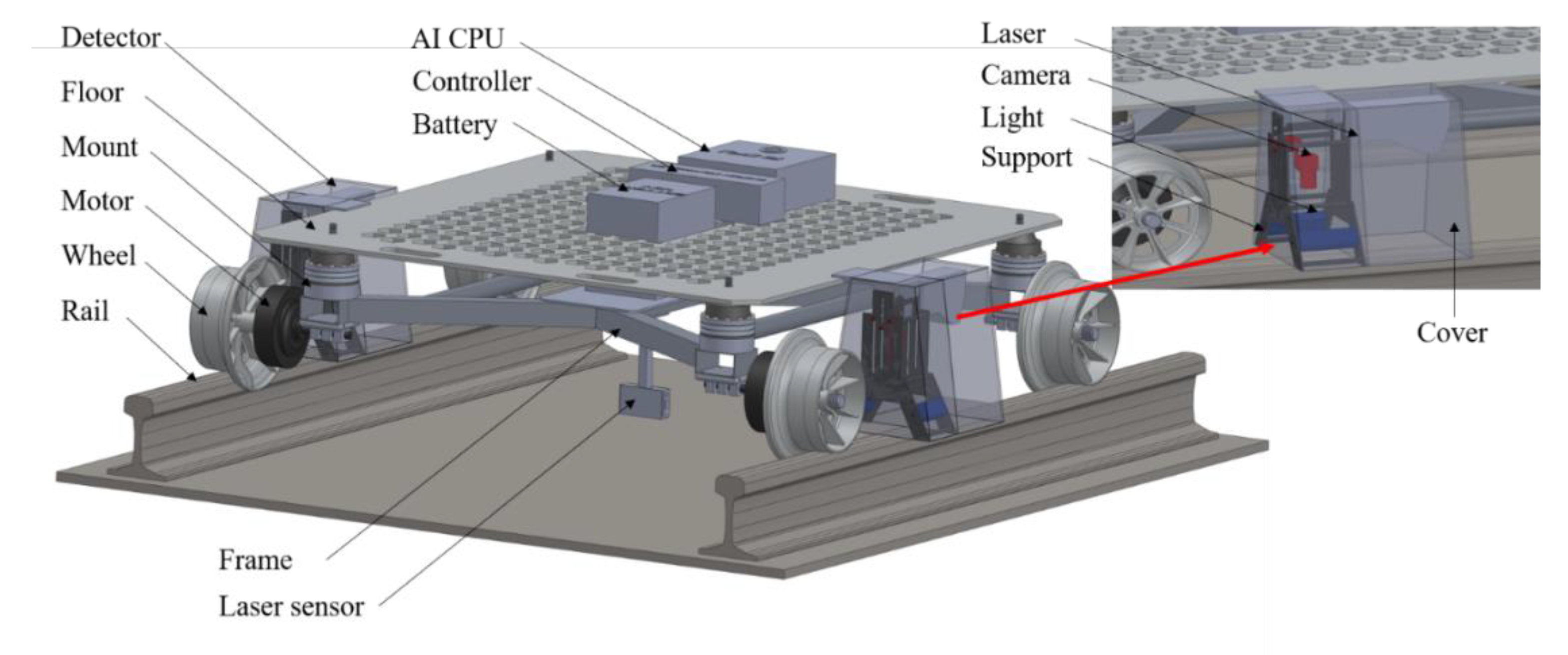
2. Concepts for the RSD Inspection Car

Based on the function of the components, the proposed RSD inspection car is divided into four main parts: the driving system, the mount system, the detector system, and the bogie body (Figure 1). Firstly, the driving system, including two electric motors, four batteries, four wheels, two laser sensors, and a controller box, generates energy for the car’s movement by converting electricity in the battery into mechanical energy in the front wheels, ensures the car moves in a straight line, and keeps an equal distance to the left side railway and to the right side railway by using input signals of two laser sensors and adjusting the speed of the left and right front-axle motors. Secondly, the detector system is an essential component of this car, which detects railway surface defects by collecting and processing data of the railway surface profile using cameras, laser sensors, and a graphic processing unit (GPU), and then provides exact position of the defects. These parts are assembled on the sprung (body) part to be isolated from the vibrations of the railway surface. Thirdly, the bogie body includes the bogie and the body. The bogie has a compact design by welding the box steels together, while the body is an aluminum floor. They support and link to other parts, such as motors, batteries, mounts, laser sensors, detectors, GPU, and controller. Finally, the mounting system consists of four mounts, placed between the sprung and un-sprung parts to isolate unwanted vibrations transmitted from the rail surface. They significantly contribute to eliminating the noise of collected images. In addition, the brake system of the vehicle is also built. Due to the relatively low speed and low weight of the inspection car, the mechanical automotive braking system is designed to stop the car. The brake system includes two motors, wires, and two friction bands. Those motors are hung on the body, while other parts are linked to the frame.

3. The Proposed MR Mount

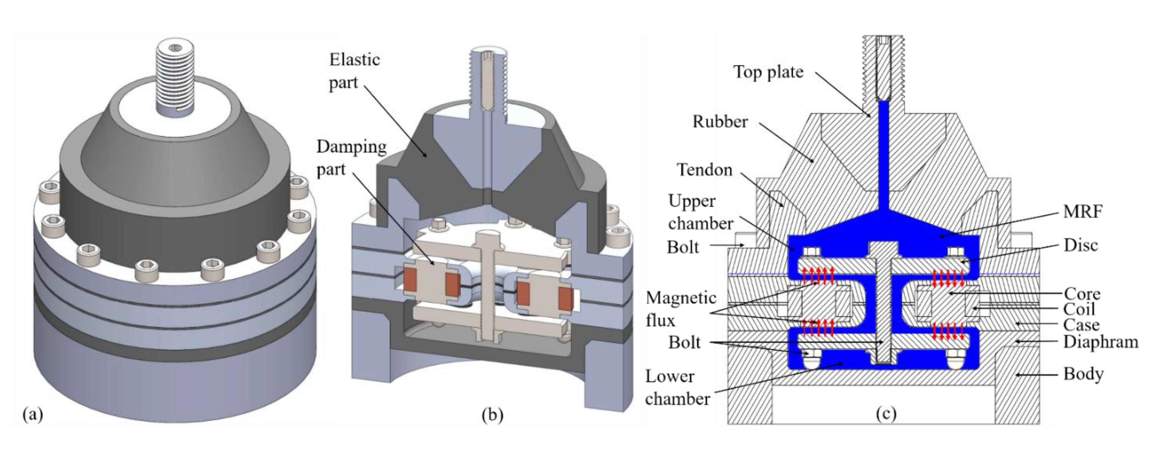
3.1. Conceptual Design of Mount

The proposed mount is composed of two main parts: elastic and damping parts (Figure 2). Firstly, the elastic part functions to receive, transmit, and absorb the vibration source from the rail surface. The rubber generates the damping force, which is relatively small, compared to that of the damping part. Secondly, the damping part generates and adjusts the damping force by supplying the current into the coil and changing its magnitude. This part includes six steel cores, six copper coils, two steel discs, two aluminum cases, and bolts. In addition, the mount also has a body component that supports and links the mount to the car frame and a diaphragm component that help to compensate volume for MRF by moving down and up. As the mount receives the excitation source, the elastic part receives vibrations and changes from hard vibrations of source to soft vibrations of the elastic part, then pumps (when the sprung part moves downwards relative to the un-sprung part) and sucks (when the sprung part moves upwards relative to the un-sprung part) the MRF flow into the radial channel. When the MRF goes through the radial channel, it is impacted by the external magnetic field. The yield magnetic field will magnetize MRF particles. The shear stress appears to resist MRF flow, increasing the pressure drop of MRF. Therefore, as the external magnetic flux changes by changing the input current magnitude into the mount, the damping force of the mount also changes.

3.2. Mathematical Model of the Mount

3.2.1. A Damping Force Model

The damping force of the mount is constructed with the assumption of the Bingham plastic behavior of the MRF. This paper used MRF 140-CG, which generated high stress up to 58 (kPa) at a magnetic field intensity of 200 (kA/m) [23]. We used the experimental data (in graph form) showing the relationship between the yield shear stress τ and the magnetic field intensity Hm for MRF 140-CG, which was published by the manufacturer, Lord Corporation. Based on these data, we approximated the polynomial function to represent the yield shear stress τ, using the least square curve-fitting method (LSM) to generate Equation (1):
τ = 2 × 10 12 H m 3 2 × 10 6 H m 2 + 0.6226 H m 389.85 ,
The difference between the pressure of the upper chamber P1 and the pressure of the lower chamber P2 equals the sum of the pressure drops generated by inertia of fluid flow ∆PI, the viscosity of fluid ∆Pμ, and the yield stress of fluid ∆Pτ. Each pressure drop for the MR mount with a valve structure using a flow mode is derived as in Equation (2). Further, the compliances of the upper chamber C1 and the lower chamber C2 also impact P1 and P2. They are determined based on the continuity equation of fluid [17]. Finally, the damping force equation of the mount is derived by the product of the upper chamber pressure P1 and the effective cross-sectional area Ap in Equation (3) [15,17,24,25]:
P 1 P 2 = Δ P I   +   Δ P μ   +   Δ P τ = I i A p Z ¨ q ¨ + 12 k μ μ Q L a n π g 3 R a n + 12 k μ μ Q π g 3 l n R o d r i + 128 μ Q L h o π D h o 4 + c τ L r a k τ g s g n Z ˙ q ˙ ,  
F m = P 1 A p = C 2 C 1 + C 2 c τ L r a k τ g s g n Z ˙ q ˙ + 12 k μ μ Q L a n π g 3 R a n + 128 μ Q L h o π D h o 4   + 12 k μ μ Q π g 3 l n R o d r i + A p Z q C 1 + C 2 + I i A p Z ¨ q ¨ A p ,
where c is the coefficient which depends on the flow velocity profile, c = [2.07–3.07] [24]; μ is the viscosity of MRF; k μ , k τ are the effective area ratio of the viscous fluid and the field fluid, respectively; Q is the flow rate ( Q = A p ( Z ˙   q ˙ ) ); Ii is the inertia coefficient of the fluid ( I i     π ρ R o d 4 / 8 g ) [15]. Structural parameters of the magnetic part include the outer radius Rod, the annular radius Ran, the inner radius ri, the inner diameter Dho, the gap g , the working radial and annular length Lra, Lan of MRF; the height of core Lho. Dynamic parameters of the car will be explained in the next section. The values of all key parameters of the proposed mount are listed in Table 1.
For convenience, a variable R μ is set as equivalent viscous resistance coefficient of the MRF flow (Equation (4)), and it depends only on structures and size of the proposed MR mount
R μ = 12 k μ μ L a n π g 3 R a n + 128 μ L h o π D h o 4   + 12 k μ μ π g 3 l n R o d r i ,
Further, the value of the term of inertial force of the MRF, I i A p ( Z ¨ q ¨ ) A p , is relatively small compared to the other terms. So, it is reasonable to neglect this term in Equation (3). Therefore, based on the formula of R μ and Q, Equation (3) can be rewritten as the following:
F m = P 1 A p = A p C 2 c τ R o r i k τ C 1 + C 2 g s g n Z ˙ q ˙ + A p 2 C 2 R μ Z ˙ q ˙ C 1 + C 2 + A p 2 Z q C 1 + C 2 ,

3.2.2. Mount Dynamic Model

The proposed RSD inspection car is a single degree of freedom (SDOF) type with a base including a bogie-wheel cluster. We assumed that (1) the mass is uniformly distributed to four mounts, (2) the vertical vibration is the primary vibration of the car, and (3) the left and right rail surface profiles are the same. Figure 3a presents the dynamic model for the quarter-car suspension system. In this model, the sprung mass displacement and motion velocity are determined in the local coordinates of Z(t), with a upward positive direction. Similarly, those of the un-sprung mass determined in the local coordinates q(t) have the same positive direction. The model is built with the denotations as the following: m, Z, Z ˙ , and Z ¨ are the mass, the absolute displacement, the velocity, and the acceleration of the sprung mass, respectively; M, q, q ˙ , and q ¨ are the mass, the absolute displacement, the velocity, and the acceleration of the base mass, respectively. The rubber body is equivalent to the spring stiffness Kr. The internal friction damping caused by the rubber is Cr. From the model in Figure 3a, the active force on the sprung mass is derived in Figure 3b. Assuming that the sprung part moves upwards of the equilibrium position of the static state, the elastic force of the rubber body FKr tends to pull the sprung mass part back to the equilibrium position; therefore, the direction of FKr will point down. The damping force caused by the internal friction of rubber FCr and the damping force generated by the pressure P1 of the upper chamber ApP1 are all in a downward direction. The inertia force of the sprung mass Fa also has a downward direction, opposite to the acceleration. The dynamic balance equation for the sprung mass is determined in Equation (6):
F a + F K r + F C r + A p P 1   = 0 ,   with   F a = m Z ¨ ,   F K r = K r Z q ,   F C r = C r Z ˙ q ˙ ,
Finally, the parameters determined in Equation (5) are substituted into Equation (6) to find the acceleration of the sprung mass as in Equation (7):
Z ¨ =   1 m K r Z q C r Z ˙ q ˙ A p 2 Z q C 1 + C 2 A p 2 C 2 R μ Z ˙   q ˙ C 1 + C 2 A p C 2 c τ R o r i k τ C 1 + C 2 g s g n Z ˙   q ˙ ,
Equation (7) is the general dynamic equation for the sprung mass. The acceleration of the sprung mass is inversely proportional to the m of the sprung mass. It is also associated with the relative displacement Z q , the relative velocity ( Z ˙ q ˙ ) , and the structure of the mount, such as the effective working area of the upper chamber, the elastic stiffness, the damping coefficient of rubber by the inertia friction, the equivalent viscous resistance coefficient generated by MRF viscosity R μ , the yield stress of MRF when the external magnetic field is applied, and the gap of MRF. Finally, the acceleration of the sprung mass is dependent on the compliances of the upper and lower chambers. The study of Jazar et al. [26] showed that the stiffness of rubber is linear in the displacement range less than or equal to 6 (mm). In this paper, the displacement of the rubber is 6 mm; thus, we can use the linearity of the rubber stiffness. The proposed mount has similar structures to the rubber and diaphragm, and its size is smaller than one-half of that of the mounts designed by Nguyen et al. [17] and Christopherson et al. [26]. So, the parameters Ks, Cs, C1, and C2 are referred to as one-half of the corresponding parameters in these studies.

4. Controller for the MR Mount

4.1. Analysis of a Skyhook Control Strategy

The desired damping force of a conventional damper is calculated following the damping force of an ideal Skyhook damper. The Skyhook damping force is determined by Equation (8), where Csky is the damping coefficient of the Skyhook damper and Z ˙   is the velocity of the piston in the Skyhook damper. The desired damping force of a conventional damper was formulated by Karrnopp et al. [20] as in Equation (9), in which Csa is the desired damping coefficient and ( Z ˙   q ˙ ) is the relative velocity of the damper piston (equivalent to the relative velocity of the mount piston). To create the desired damping force, we must change the desired damping coefficient value according to the Skyhook damping coefficient at the velocity of the sprung and un-sprung mass, using the following formula:
F d = C s k y Z ˙ ,   and   F s a = C s a Z ˙ q ˙ ,
F d = F s a       C s a = C s k y Z ˙ Z ˙ q ˙ ,
In the actual control of damping in the suspension system, a high damping force is required in the case of rebound (extension) motion Z ˙ ( Z ˙ q ˙ )     0 . In contrast, it requires a low damping force in the case of jounce (compression) motion Z ˙ ( Z ˙ q ˙ ) < 0 . Therefore, two types of control change the desired damping coefficient, including the on–off type and continuous variable type, which are introduced in Figure 4a,b. For on–off type, there are two states, i.e., with and without the magnetic field applied, leading to the generation of the force or not, respectively. This type is simple to control; however, the range of damping coefficient is discrete. For the continuous variable, the damping coefficient varies on a continuous scale following a specific function, which will help the device produce the desired force range as well as to avoid fast state transitions that reduce the jerk phenomenon. Figure 4c,d illustrate the desired damping force control domain. The damping coefficient control of continuous variable type can provide a larger controllable force domain which enhances the effectiveness of the controller. The damping coefficient control following the ideal Skyhook damping coefficient of continuous variable type is given as follows:
C s a = C s k y Z ˙ Z ˙ q ˙                   Z ˙ Z ˙ q ˙     0 C m i n                         Z ˙ Z ˙ q ˙ < 0 ,
In the control Equation (10), the value of the desired damping coefficient will increase to infinity when the denominator ( Z ˙ q ˙ ) is too small or close to zero. To overcome this problem, the upper value of the damping coefficient is limited by Equation (11) [27]:
C s a = m a x C m i n , min [ C s k y Z ˙ Z ˙ q ˙ ,   C m a x ] ]                   Z ˙ Z ˙ q ˙   0 C m i n                                                                   Z ˙ Z ˙ q ˙ < 0 ,
When the movement between the body and the sprung mass of the mount tends to separate ( Z ˙ ( Z ˙ q ˙ )     0 ) , the semi-active controller for the mount will generate the desired damping coefficient of m a x C m i n , min [ C s k y ( Z ˙ / ( Z ˙ q ˙ ) ) ,   C m a x ] ] to prevent this movement. On the contrary, if the movement between the body and the sprung mass of the mount tends to be close to each other ( Z ˙ ( Z ˙ q ˙ ) < 0 ), the controller will generate a small damping factor of Cmin to hinder this jounce. A limit of the damping coefficient control is set to [Cmin, Cmax] when ( Z ˙   q ˙ ) is close to zero.

4.2. Diagram for Semi-Active Controller

A control diagram for the car using the semi-active mount is shown in Figure 5a. The input dynamic signals of the sprung mass and the un-sprung (base) mass are determined by the accelerometer, which fastens on the sprung and un-sprung mass. After defining the acceleration value, the controller calculates the displacement and velocity of these two parts. Figure 5b presents the diagram of damping force control. From the Skyhook control strategy, a formula of the desired damping coefficient is constructed based on dynamic parameters of the sprung and un-sprung mass. The relationship between the desired damping force and the current amplifier is also formulated based on the magnetic field intensity, the yield stress, and the damping force. Finally, a simulation program is built on Matlab Simulink, using the Runge–Kutta method with a step size of 0.001 and a simulation time of 50 (s).

5. Results and Discussion

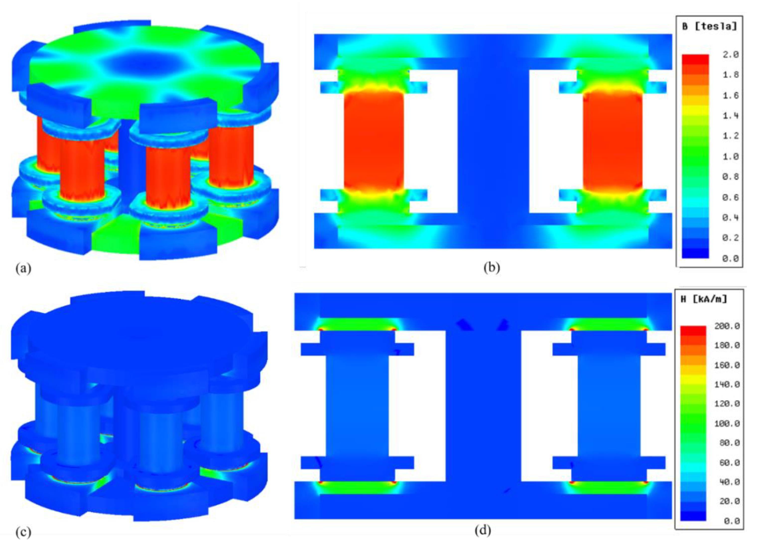
5.1. Results of Magnetic Simulation

The magnetic density of the proposed mount is presented in Figure 6a,b, in which all components have a magnetic density close to the magnetic saturation point (less than 2 (T)). In particular, in the MRF layer, the magnetic density is uniformly distributed from up to down, and from outside to inside in the range of 1.0–1.2 (T), which is very close to the saturation value of MRF in Figure 6b. Similarly, Figure 6c,d show the magnetic field intensity in the mount. The magnetic intensity at the working MRF region (Hm) peaks at approximately 200 (kA/m) and has uniform distribution from up to down and from outside to inside in the range of 120–140 (kA/m), and the remaining areas (such as disc and core) have a magnetic intensity of less than 20 (kA/m).

5.2. Results of the Control Simulation

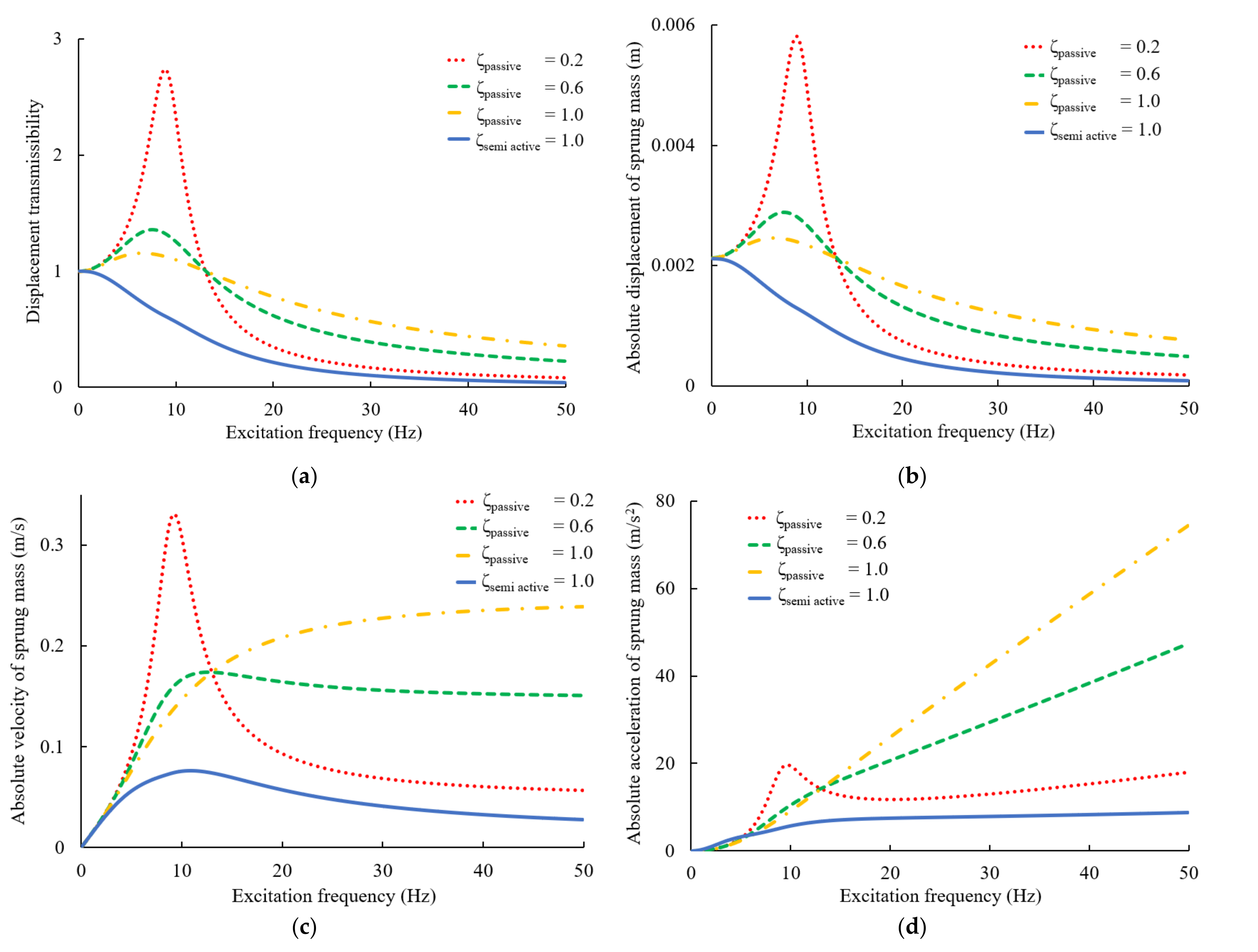
5.2.1. Response of the Frequency Domain

Figure 7 shows the root mean square (RMS) for the dynamic response of the frequency domain in passive and semi-active mounts. Based on the displacement transmissibility R M S Z / q (Figure 7a) and absolute displacement R M S Z (Figure 7b), within the excitation frequency range of 0–50 (Hz), the performance of semi-active mounts is much better than that of passive mounts. First, the displacement transmissibility and absolute displacement of the car using the semi-active controller are always under one unit, meaning that the displacement of the sprung mass is always lower than the displacement of the un-sprung mass. Second, the resonance at the natural frequency disappears and the displacement reduces by 83.33% at this frequency. Similarly, Figure 7c,d present the absolute velocity and the acceleration of the semi-active mount, respectively. These responses of the semi-active mount are higher than those of the passive mount. They reduce by 77% for the velocity and 70% for the acceleration at the resonance frequency.

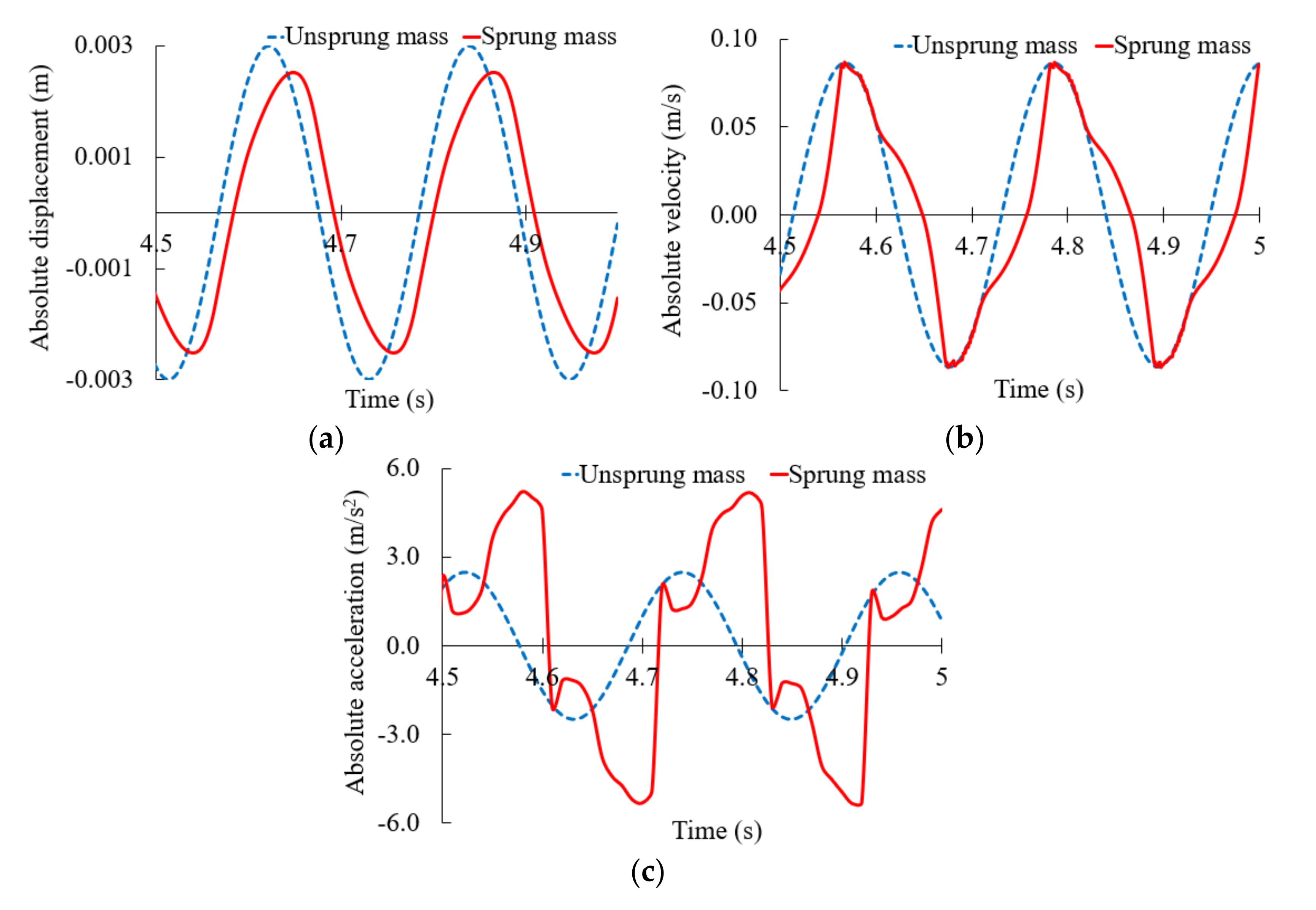
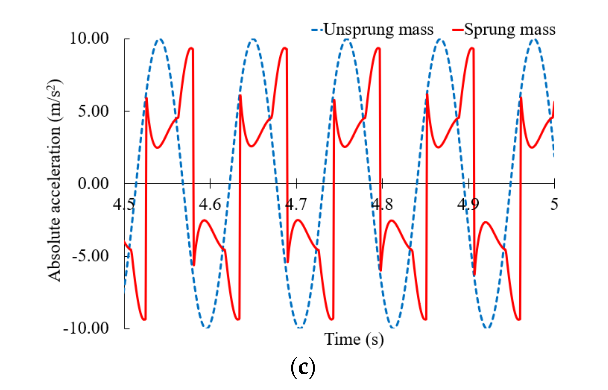
5.2.2. Response of the Time Domain with a Semi-Active Mount

To provide a clear view of the dynamic of the sprung and un-sprung parts, Figure 8, Figure 9 and Figure 10 show computer simulation results without RMS. The un-sprung motion is sinusoidal, with three cases corresponding to three different frequencies, equal to 0.5-, 1.0-, and 2.0-fold the natural frequency (Figure 8, Figure 9 and Figure 10, respectively). In all cases, the damping of the Skyhook damper is equal to the damping of the passive mount at the damping ratio of 1.0. In Figure 8, the dynamic of the sprung mass is close to that of the un-sprung mass. The lock phenomenon appeared sometimes where ( Z ˙ = q ˙ and Z ¨ =   q ¨ ). The acceleration of the sprung mass is higher than that of the un-sprung mass; nevertheless, this issue can be neglected because the acceleration of the sprung mass is low at a low frequency. In Figure 9, it is observed that the dynamic of the sprung mass is better than that of the un-sprung mass and the lock phenomenon does not occur. Finally, good performance for dynamics is clearly shown at higher frequencies (Figure 10). The acceleration of the sprung mass is less than 10 (m/s2), while the acceleration of the base is very high at 40 (m/s2).

6. Conclusions

The configuration of the RSD inspection car using an MR mount as a suspension system was analyzed and designed to detect rail surface defects. An MR mount with multi-poles and multi-layers was designed and simulated. This mount design generated a uniform distribution of the magnetic field density over the working MRF region close to the saturation point of the MRF. In addition, a Skyhook control strategy was analyzed and applied to control this car. The dynamic simulation results showed that the MR mount had better vibration isolation performance than conventional passive mounts and the suspension vibration to the inspection devices was significantly reduced.

Author Contributions

Conceptualization and writing—review, Y.S.; methodology, data collection and writing, T.-L.H. All authors have read and agreed to the published version of the manuscript.

Funding

This research was funded by Ministry of Science and Technology, Taiwan, grant number MOST 110-2221-E-027-081.

Institutional Review Board Statement

Not applicable.

Informed Consent Statement

Not applicable.

Acknowledgments

We thank project supporting from Ministry of Science and Technology, Taiwan.

Conflicts of Interest

The authors declare no conflict of interest.

References

  1. Yu, H.; Li, Q.; Tan, Y.; Gan, J.; Wang, J.; Geng, Y.-a.; Jia, L. A Coarse-to-Fine Model for Rail Surface Defect Detection. IEEE Trans. Instrum. Meas. 2019, 68, 656–666. [Google Scholar] [CrossRef]
  2. Zhang, H.; Song, Y.; Chen, Y.; Zhong, H.; Liu, L.; Wang, Y.; Akilan, T.; Wu, Q.M.J. Multi-Model Rail Surface Defect Inspection System Based on Convolutional Neural Networks. IEEE Trans. Intell. Transp. Syst. 2021, 1–16. [Google Scholar] [CrossRef]
  3. Bentoumi, M.; Aknin, P.; Bloch, G. On-line rail defect diagnosis with differential eddy current probes and specific detection processing. Eur. Phys. J. Appl. Phys. 2003, 23, 227–233. [Google Scholar] [CrossRef] [Green Version]
  4. Masmoudi, M.; Yaacoubi, S.; Koabaz, M.; Akrout, M.; Skaiky, A. On the use of ultrasonic guided waves for the health monitoring of rails. Proc. Inst. Mech. Eng. Part F J. Rail Rapid Transit 2022, 236, 469–489. [Google Scholar] [CrossRef]
  5. Zhang, X.; Feng, N.; Wang, Y.; Shen, Y. Acoustic emission detection of rail defect based on wavelet transform and Shannon entropy. J. Sound Vib. 2015, 339, 419–432. [Google Scholar] [CrossRef]
  6. Lee, Y.W.; Lee, C.W. Dynamic analysis and control of an active engine mount system. Proc. Inst. Mech. Eng. Part D J. Automob. Eng. 2002, 216, 921–931. [Google Scholar] [CrossRef]
  7. Hausberg, F.; Scheiblegger, C.; Pfeffer, P.; Plöchl, M.; Hecker, S.; Rupp, M. Experimental and analytical study of secondary path variations in active engine mounts. J. Sound Vib. 2015, 340, 22–38. [Google Scholar] [CrossRef]
  8. Lin, Z.; Wu, M. Dynamic characterization of controlled multi-channel semi-active magneto-rheological fluid mount. Mech. Sci. 2021, 12, 751–764. [Google Scholar] [CrossRef]
  9. Liu, Q.; Bai, G.-D.; Liu, Z.-H.; Bai, X.-X.F.; Du, H.; Chen, P.; Qian, L.-J. Magneto-rheological semi-active mount system for engines: Prototyping and testing. Proc. Inst. Mech. Eng. Part D J. Automob. Eng. 2020, 234, 3081–3094. [Google Scholar] [CrossRef]
  10. Nguyen, V.; Zhang, J.; Yang, X. Low-Frequency Performance Analysis of Semi-Active Cab’s Hydraulic Mounts of an Off-Road Vibratory Roller. Shock. Vib. 2019, 2019, 1–15. [Google Scholar] [CrossRef]
  11. Yang, S.; Han, C.; Shin, C.; Choi, S.; Jung, J.; Kim, S.; Kim, I. Dynamic characteristics of passive and semi-active cabin mounts for vibration control of a wheel loader. Int. J. Heavy Veh. Syst. 2019, 26, 239. [Google Scholar] [CrossRef]
  12. Hong, S.-R.; Choi, S.-B.; Han, M.-S. Vibration control of a frame structure using electro-rheological fluid mounts. Int. J. Mech. Sci. 2002, 44, 2027–2045. [Google Scholar] [CrossRef]
  13. Wang, M.; Yao, G.-f.; Zhao, J.-z.; Qin, M. A novel design of semi-active hydraulic mount with wide-band tunable notch frequency. J. Sound Vib. 2014, 333, 2196–2211. [Google Scholar] [CrossRef]
  14. Truong, T.Q.; Ahn, K.K. A new type of semi-active hydraulic engine mount using controllable area of inertia track. J. Sound Vib. 2010, 329, 247–260. [Google Scholar] [CrossRef]
  15. Chen, P.; Bai, X.-X.; Qian, L.-J.; Choi, S.-B. A magneto-rheological fluid mount featuring squeeze mode: Analysis and testing. Smart Mater. Struct. 2016, 25, 055002. [Google Scholar] [CrossRef]
  16. Choi, S.-B.; Hong, S.-R.; Sung, K.-G.; Sohn, J.-W. Optimal control of structural vibrations using a mixed-mode magneto-rheological fluid mount. Int. J. Mech. Sci. 2008, 50, 559–568. [Google Scholar] [CrossRef]
  17. Nguyen, Q.H.; Choi, S.B.; Lee, Y.S.; Han, M.S. Optimal design of high damping force engine mount featuring MR valve structure with both annular and radial flow paths. Smart Mater. Struct. 2013, 22, 115024. [Google Scholar] [CrossRef]
  18. Phu, D.X.; Choi, S.B.; Lee, Y.S.; Han, M.S. Design of a new engine mount for vertical and horizontal vibration control using magneto-rheological fluid. Smart Mater. Struct. 2014, 23, 117001. [Google Scholar] [CrossRef]
  19. York, D.; Wang, X.; Gordaninejad, F. A New Magnetorheological Mount for Vibration Control. J. Vib. Acoust. 2011, 133, 031003. [Google Scholar] [CrossRef]
  20. Karnopp, D.; Crosby, M.J.; Harwood, R.A. Vibration Control Using Semi-Active Force Generators. J. Eng. Ind. 1974, 96, 619–626. [Google Scholar] [CrossRef]
  21. Pan, D.Y.; Gao, X.; Xia, C.G.; Cai, H. Research on Fuzzy PID Control for Power-Train MR Mount System. Appl. Mech. Mater. 2013, 397–400, 1304–1308. [Google Scholar] [CrossRef]
  22. Fu, J.; Bai, J.; Lai, J.; Li, P.; Yu, M.; Lam, H.-K. Adaptive fuzzy control of a magneto-rheological elastomer vibration isolation system with time-varying sinusoidal excitations. J. Sound Vib. 2019, 456, 386–406. [Google Scholar] [CrossRef]
  23. Data, L.T. MRF-140CG Magneto-Rheological Fluid. 2008. Available online: https://lordfulfillment.com/pdf/44/DS7012_MRF-140CGMRFluid.pdf (accessed on 10 April 2022).
  24. Nguyen, Q.-H.; Han, Y.-M.; Choi, S.-B.; Wereley, N.M. Geometry optimization of MR valves constrained in a specific volume using the finite element method. Smart Mater. Struct. 2007, 16, 2242–2252. [Google Scholar] [CrossRef]
  25. Wang, D.H.; Ai, H.X.; Liao, W.H. A magneto-rheological valve with both annular and radial fluid flow resistance gaps. Smart Mater. Struct. 2009, 18, 115001. [Google Scholar] [CrossRef]
  26. Christopherson, J.; Jazar, G.N. Dynamic behavior comparison of passive hydraulic engine mounts. Part 2: Finite element analysis. J. Sound Vib. 2006, 290, 1071–1090. [Google Scholar]
  27. Liu, Y. Semi-Active Damping Control for Vibration Isolation of Base Disturbances. Ph.D. Thesis, University of Southampton, Southampton, England, 2004. [Google Scholar]
Figure 1. The proposed configuration of the RSD inspection car.
Applsci 12 07336 g001
Figure 2. The proposed MR mount: (a) isometric view; (b) 3D and (c) 2D cross-sectional views.
Applsci 12 07336 g002
Figure 3. Dynamic model: (a) a quarter-car suspension system; (b) the active force on the sprung mass.
Applsci 12 07336 g003
Figure 4. Damping coefficient control of (a) the on–off type (b), the continuous variable type and controllable force region, (c) the on–off type and (d) the continuous variable type.
Applsci 12 07336 g004
Figure 5. Semi-active controller: (a) full control diagram; (b) damping force control.
Applsci 12 07336 g005
Figure 6. Magnetic density B on (a) full view and (b) cross-section view of mount, and magnetic intensity H on (c) full view and (d) cross-section view of mount.
Applsci 12 07336 g006
Figure 7. Response of the frequency domain: (a) transmissibility, (b) absolute displacement, (c) absolute velocity, and (d) absolute acceleration of the sprung mass.
Applsci 12 07336 g007
Figure 8. Response of the time domain of (a) displacement, (b) velocity, and (c) acceleration of the sprung and un-sprung mass with the excitation frequency equal to a half of the natural frequency.
Applsci 12 07336 g008
Figure 9. Response of the time domain of (a) displacement, (b) velocity, and (c) acceleration of the sprung and un-sprung mass with the excitation frequency equal to the natural frequency.
Applsci 12 07336 g009aApplsci 12 07336 g009b
Figure 10. Response of the time domain of (a) displacement, (b) velocity, and (c) acceleration of the sprung and un-sprung mass with the excitation frequency equal to 2-fold the natural frequency.
Applsci 12 07336 g010
Table 1. Details of the RSD inspection car’s components.
ParametersValues
Stiffness of the rubber, Ks (kN/m)50
Damping coefficient of the rubber, Cs (N·m/s)50
Compliance of the upper chamber, C1 (m5/N)2 × 10−10
Compliance of the lower chamber, C2 (m5/N)2 × 10−8
Effective area of the upper chamber cross-section, Ap (m2)7.065 × 10⁻⁴
Gap of MRF, g (m)0.002
Outer radius of the magnetic part Rmp (m)0.03
Equivalent viscous coefficient caused by MRF, Rμ (Ns/m5)9.91 × 107
Ratio of the effective area caused by the magnetic field, kt0.58
Weight of the sprung mass per each mount, m (kg)15
Density of MRF 140-CG (kg/m−3)3540
Publisher’s Note: MDPI stays neutral with regard to jurisdictional claims in published maps and institutional affiliations.

