
Incident Angle Dependence of the Waveform of the Polarization-Sensitive Photoresponse in CuSe/Se Thin Film

 ,
, 
Abstract
:1. Introduction
2. Materials and Methods
3. Results and Discussion
4. Conclusions
Supplementary Materials
Author Contributions
Funding
Institutional Review Board Statement
Informed Consent Statement
Data Availability Statement
Acknowledgments
Conflicts of Interest
Nomenclature
| Symbol | |
| α | Angle of incidence |
| Se | Selenium |
| Cu | Copper |
| t-Se | Trigonal selenium |
| Ein | Laser pulse energy |
| Rin | Input impedance of the oscilloscope |
| jx | Longitudinal photocurrent |
| jy | Transverse photocurrent |
| Ux | Extreme values of the voltage pulses at the experimental geometry when the measuring electrodes were placed perpendicular to the plane of incidence |
| Uy | Extreme values of the voltage pulses at the experimental geometry when the measuring electrodes were placed parallel to the plane of incidence |
| t | Time |
| ηx | Efficiency of converting light into longitudinal photocurrent |
| ηy | Efficiency of converting light into transverse photocurrent |
| Φ | Angle between the plane of polarization and the radiation incidence plane on the film |
| σ | Radiation incidence plane on the film |
| n | Normal to the film surface |
| A | Measuring electrode |
| B | Measuring electrode |
| k | The wave vector of the optical field |
| E | Electric field vector of the incident radiation |
| Electric field vector of the refracted beam | |
| x, y | Axes of the rectangular coordinate system |
| x′ | Axis, which lies in the σ plane and perpendicular to k |
| x″ | Axis, which lies in the refraction plane coinciding with the plane of incidence and perpendicular to the wave vector of the refracted beam |
| tp | Complex Fresnel refractive index for p-polarizations |
| ts | Complex Fresnel refractive index for s-polarizations |
| Complex refractive index | |
| Real refractive index that determines the phase velocity | |
| Absorption coefficient | |
| Phase shift between the components of the refracted beam with p- and s-polarizations | |
| Phase shift of the p-component of the beam, resulting from refraction at the interface between two media with a complex refractive index | |
| Phase shift of the s-component of the beam, resulting from refraction at the interface between two media with a complex refractive index | |
| Initial phase shift between the p- and s-components before refraction | |
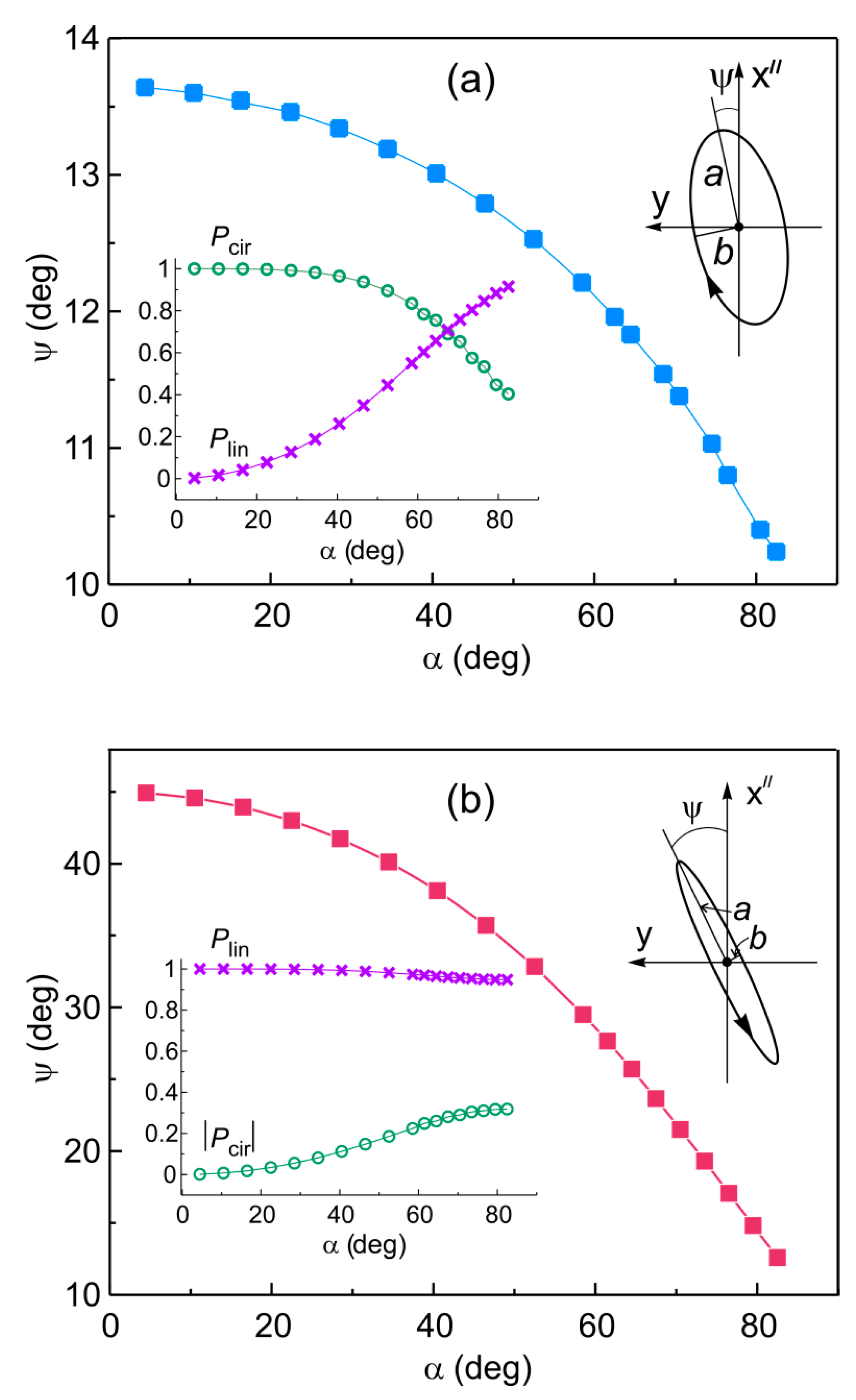
| a | Semi-major axis of the refracted beam polarization ellipse |
| b | Semi-minor axis of the refracted beam polarization ellipse |
| Pcir | Degree of circular polarization |
| Plin | Degree of linear polarization |
| ψ | Angle between the semi-major axis of the refracted beam polarization ellipse and axis x″ |
| γ | Sign of circular polarization |
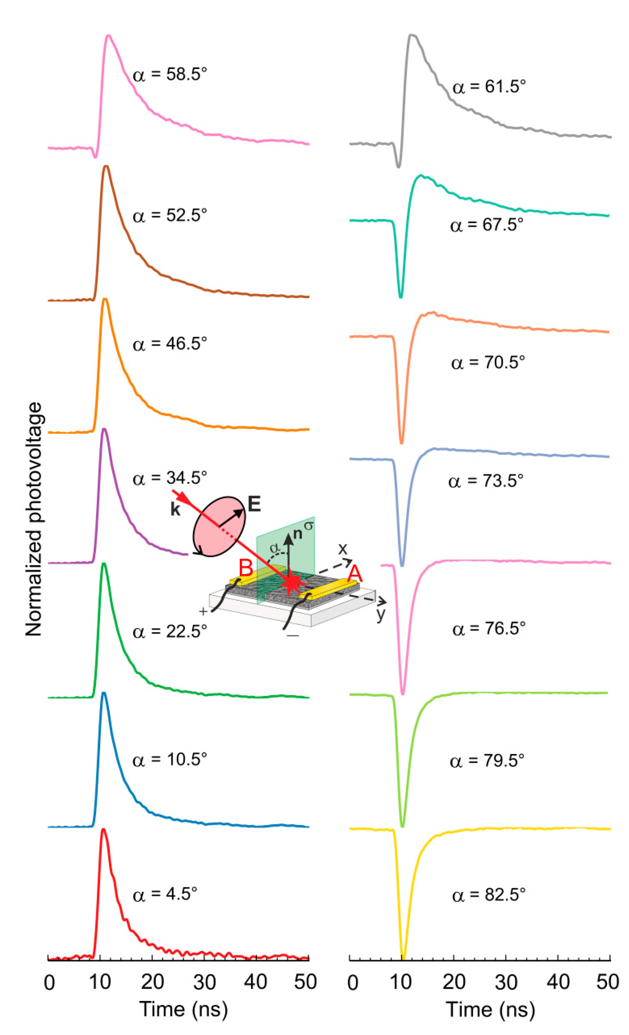
| Uy(t, α) | Waveforms of the transverse photovoltage pulses |
| Acir | Positive coefficient of the circular photocurrent at a given α |
| Alin | Positive coefficient of the linear photocurrent at a given α |
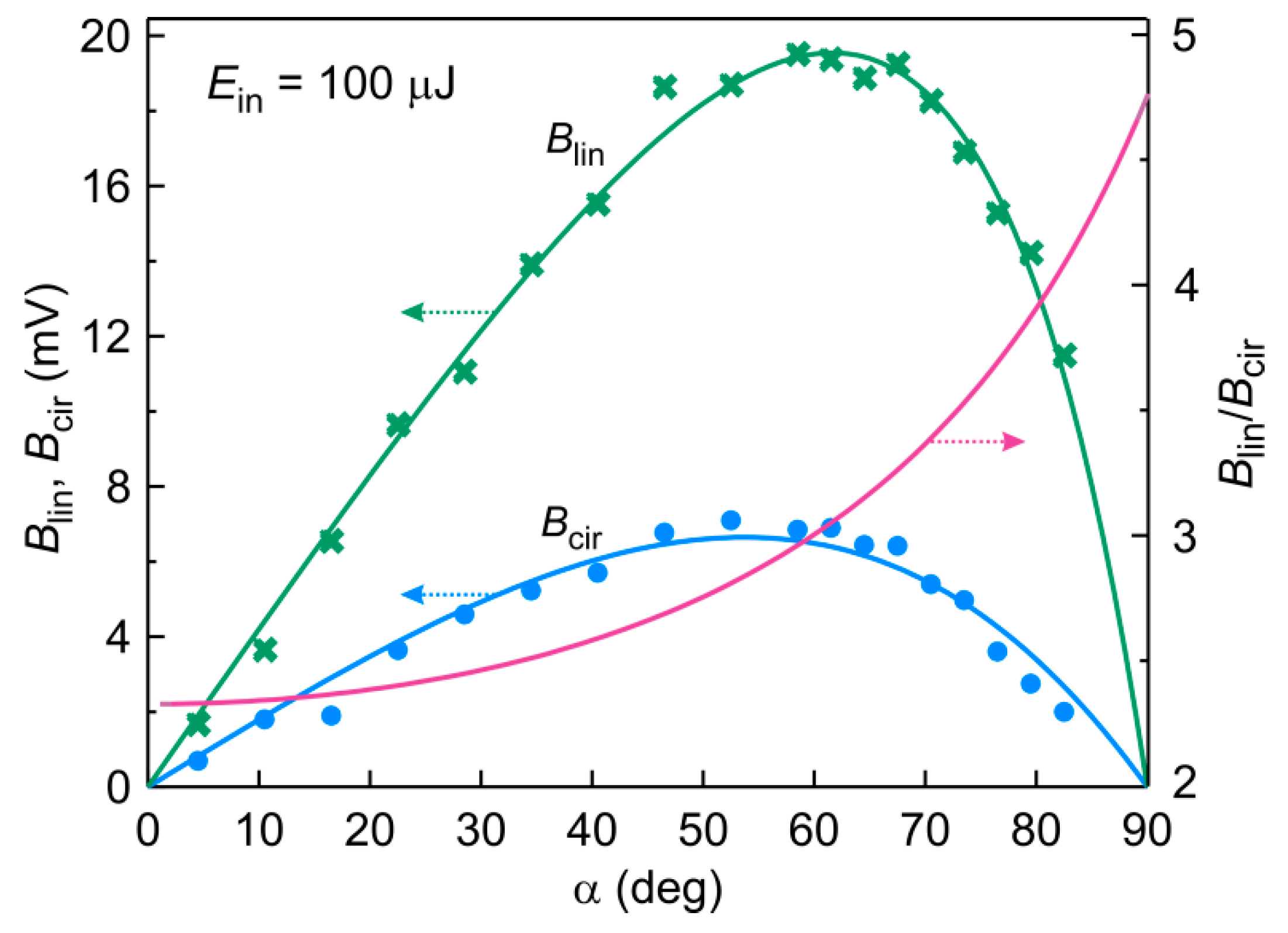
| Bcir | Positive coefficient (for positive α) depending on α and characterizing the circular contribution |
| Blin | Positive coefficient (for positive α) depending on α and characterizing the linear contribution |
| Transverse photovoltage waveform normalized to its maximum value, recorded at angle α close to zero for circular polarizations | |
| Transverse photovoltage waveform normalized to its maximum values, recorded at angle α close to zero for linear polarizations | |
| Abbreviations | |
| PSPC | Polarization sensitive photocurrent |
| CPC | Circular photocurrent |
| LPC | Linear photocurrent |
| CPGE | Circular photogalvanic effect |
| PGE | Photogalvanic effect |
| PDE | Photon drag effect |
| SEM | Scanning electron microscope |
| FWHM | Full width at half maximum |
References
- Wang, J.; Zhou, Y.J.; Xiang, D.; Ng, S.J.; Watanabe, K.; Taniguchi, T.; Eda, G. Polarized light-emitting diodes based on anisotropic excitons in few-layer ReS2. Adv. Mater. 2020, 32, 2001890. [Google Scholar] [CrossRef] [PubMed]
- Wang, X.; Wang, Q.; Zhang, X.; Miao, J.; Cheng, J.; He, T.; Li, Y.; Tang, Z.; Chen, R. Circularly polarized light source from self-assembled hybrid nanoarchitecture. Adv. Opt. Mater. 2022, 2022, 2200761. [Google Scholar] [CrossRef]
- Seo, I.C.; Lim, Y.; An, S.C.; Woo, B.H.; Kim, S.; Son, J.G.; Yoo, S.; Park, Q.H.; Kim, J.Y.; Jun, Y.C. Circularly polarized emission from organic-inorganic hybrid perovskites via chiral fano resonances. ACS Nano 2021, 15, 13781–13793. [Google Scholar] [CrossRef] [PubMed]
- Ivchenko, E.L. Optical Spectroscopy of Semiconductor Nanostructures; Springer: Berlin/Heidelberg, Germany, 2004. [Google Scholar]
- Gurevich, V.L.; Laiho, R. Photomagnetism of metals. First observation of dependence on polarization of light. Phys. Solid State 2000, 42, 1807–1812. [Google Scholar] [CrossRef]
- Singh, A.; Li, X.; Protasenko, V.; Galantai, G.; Kuno, M.; Xing, H.; Jena, D. Polarization-sensitive nanowire photodetectors based on solution-synthesized CdSe quantum-wire solids. Nano Lett. 2007, 7, 2999–3006. [Google Scholar] [CrossRef] [PubMed]
- Luo, Y.; Hu, Y.; Xie, Y. Highly polarization-sensitive, visible-blind and self-powered ultraviolet photodetection based on two-dimensional wide bandgap semiconductors: A theoretical prediction. J. Mater. Chem. A 2019, 7, 27503–27513. [Google Scholar] [CrossRef]
- Zhao, Q.; Gao, F.; Chen, H.; Gao, W.; Xia, M.; Pan, Y.; Shi, H.; Su, S.; Fang, X.; Li, J. High performance polarization-sensitive self-powered imaging photodetectors based on a p-Te/n-MoSe2 van der Waals heterojunction with strong interlayer transition. Mater. Horiz. 2021, 8, 3113–3123. [Google Scholar] [CrossRef]
- Qian, L.; Zhao, J.; Xie, Y. Enhanced photogalvanic effect in the two-dimensional MgCl2/ZnBr2 vertical heterojunction by inhomogenous tensile stress. Front. Phys. 2022, 17, 13502. [Google Scholar] [CrossRef]
- Karch, J.; Olbrich, P.; Schmalzbauer, M.; Zoth, C.; Brinsteiner, C.; Fehrenbacher, M.; Wurstbauer, U.; Glazov, M.M.; Tarasenko, S.A.; Ivchenko, E.L.; et al. Dynamic Hall effect driven by circularly polarized light in a graphene layer. Phys. Rev. Lett. 2010, 105, 227402. [Google Scholar] [CrossRef]
- Ganichev, S.D.; Ivchenko, E.L.; Prettl, W. Photogalvanic effects in quantum wells. Phys. E Low-Dimens. Syst. Nanostruct. 2002, 14, 166–171. [Google Scholar]
- Pan, Y.; Wang, Q.Z.; Yeats, A.L.; Pillsbury, T.; Flanagan, T.C.; Richardella, A.; Zhang, H.; Awschalom, D.D.; Liu, C.X.; Samarth, N. Helicity dependent photocurrent in electrically gated (Bi1-x Sb x )2Te3 thin films. Nat. Commun. 2017, 8, 1037. [Google Scholar] [CrossRef] [Green Version]
- Zhang, Z.; Zhang, R.; Liu, B.; Xie, Z.L.; Xiu, X.Q.; Han, P.; Lu, H.; Zheng, Y.D.; Chen, Y.H.; Tang, C.G.; et al. Circular photogalvanic effect at inter-band excitation in InN. Solid State Commun. 2008, 145, 159–162. [Google Scholar] [CrossRef]
- Mikheev, G.M.; Kogai, V.Y.; Mikheev, K.G.; Mogileva, T.N.; Saushin, A.S.; Svirko, Y.P. Polarization-sensitive photoresponse of the CuSe/Se nanocomposite prepared by vacuum thermal deposition. Mater. Today Commun. 2019, 21, 100656. [Google Scholar] [CrossRef]
- Hägele, D.; Oestreich, M.; Rühle, W.W.; Nestle, N.; Eberl, K. Spin transport in GaAs. Appl. Phys. Lett. 1998, 73, 1580–1582. [Google Scholar] [CrossRef]
- Okada, K.N.; Ogawa, N.; Yoshimi, R.; Tsukazaki, A.; Takahashi, K.S.; Kawasaki, M.; Tokura, Y. Enhanced photogalvanic current in topological insulators via Fermi energy tuning. Phys. Rev. B 2016, 93, 081403(R). [Google Scholar] [CrossRef] [Green Version]
- Yu, J.; Zhu, K.; Zeng, X.; Chen, L.; Chen, Y.; Liu, Y.; Yin, C.; Cheng, S.; Lai, Y.; Huang, J.; et al. Helicity-dependent photocurrent of the top and bottom Dirac surface states of epitaxial thin films of three-dimensional topological insulators Sb2Te3. Phys. Rev. B 2019, 100, 235108. [Google Scholar] [CrossRef]
- Mikheev, G.M.; Styapshin, V.M. Nanographite analyzer of laser polarization. Instrum. Exp. Tech. 2012, 55, 85–89. [Google Scholar] [CrossRef]
- Akbari, M.; Ishihara, T. Polarization dependence of transverse photo-induced voltage in gold thin film with random nanoholes. Opt. Express 2017, 25, 2143–2152. [Google Scholar] [CrossRef] [Green Version]
- Roy, S.; Manna, S.; Mitra, C.; Pal, B. Photothermal Control of Helicity-Dependent Current in Epitaxial Sb2Te2Se Topological Insulator Thin-Films at Ambient Temperature. ACS Appl. Mater. Interfaces 2022, 14, 9909–9916. [Google Scholar] [CrossRef]
- Mirzaee, S.M.A.; Lebel, O.; Nunzi, J.-M. A simple unbiased hot-electron polarization-sensitive near- infrared photo-detector. ACS Appl. Mater. Interfaces 2018, 10, 11862–11871. [Google Scholar] [CrossRef]
- Li, W.; Coppens, Z.J.; Besteiro, L.V.; Wang, W.; Govorov, A.O.; Valentine, J. Circularly polarized light detection with hot electrons in chiral plasmonic metamaterials. Nat. Commun. 2015, 6, 8379. [Google Scholar] [CrossRef]
- Schulz, M.; Balzer, F.; Scheunemann, D.; Arteaga, O.; Lützen, A.; Meskers, S.C.J.; Schiek, M. Chiral excitonic organic photodiodes for direct detection of circular polarized light. Adv. Funct. Mater. 2019, 29, 1900684. [Google Scholar] [CrossRef]
- Wang, L.; Xue, Y.; Cui, M.; Huang, Y.; Xu, H.; Qin, C.; Yang, J.; Dai, H.; Yuan, M. A chiral reduced-dimension perovskite for an efficient flexible circularly polarized light photodetector. Angew. Chemie 2020, 132, 6504–6512. [Google Scholar] [CrossRef]
- Hao, J.; Lu, H.; Mao, L.; Chen, X.; Beard, M.C.; Blackburn, J.L. Direct detection of circularly polarized light using chiral copper chloride-carbon nanotube heterostructures. ACS Nano 2021, 15, 7608–7617. [Google Scholar] [CrossRef] [PubMed]
- Belinicher, V.I.; Sturman, B.I. The photogalvanick effect in media lacking of a center of symmetry. Sov. Phys. Uspekhi 1980, 23, 199–223. [Google Scholar] [CrossRef]
- Ganichev, S.D.; Prettl, W.J. Spin photocurrents in quantum wells. Phys. Condens. Matter. 2003, 15, R935–R983. [Google Scholar] [CrossRef]
- Zhang, Y.; Cao, R.; Hu, Y.; Wang, Y.; Xie, Y. A promising polarization-sensitive ultraviolet photodetector based on the two-dimensional ZrNBr-ZrNCl lateral heterojunction with enhanced photoresponse: A theoretical prediction. Appl. Surf. Sci. 2021, 560, 149907. [Google Scholar] [CrossRef]
- Ivchenko, E.L. Circular photogalvanic effect in nanostructures. Physics-Uspekhi 2002, 45, 1299–1303. [Google Scholar] [CrossRef]
- Ivchenko, E.L.; Spivak, B. Circular photogalvanic effect and related effects in chiral carbon nanotubes. Physica 2003, 17, 376–379. [Google Scholar] [CrossRef]
- Dhara, S.; Mele, E.J.; Agarwal, R. Voltage-tunable circular photogalvanic effect in silicon nanowires. Science 2015, 349, 726–729. [Google Scholar] [CrossRef] [Green Version]
- Moayed, M.M.R.; Li, F.; Beck, P.; Schober, J.-C.; Klinke, C. Anisotropic circular photogalvanic effect in colloidal tin sulfide nanosheets. Nanoscale 2020, 12, 6256–6262. [Google Scholar] [CrossRef]
- Hubmann, S.; Budkin, G.V.; Otteneder, M.; But, D.; Sacré, D.; Yahniuk, I.; Diendorfer, K.; Bel’kov, V.V.; Kozlov, D.A.; Mikhailov, N.N.; et al. Symmetry breaking and circular photogalvanic effect in epitaxial CdxHg1-xTe films. Phys. Rev. Mater. 2020, 4, 043607. [Google Scholar] [CrossRef]
- Sun, X.; Adamo, G.; Eginligil, M.; Krishnamoorthy, H.N.S.; Zheludev, N.I.; Soci, C. Topological insulator metamaterial with giant circular photogalvanic effect. Sci. Adv. 2021, 7, eabe5748. [Google Scholar] [CrossRef] [PubMed]
- Glazov, M.M.; Ganichev, S.D. High frequency electric field induced nonlinear effects in graphene. Phys. Rep. 2014, 535, 101–138. [Google Scholar] [CrossRef] [Green Version]
- Mikheev, G.M.; Saushin, A.S.; Vanyukov, V.V.; Mikheev, K.G.; Svirko, Y.P. Femtosecond circular photon drag effect in the Ag/Pd nanocomposite. Nanoscale Res. Lett. 2017, 12, 39. [Google Scholar] [CrossRef] [PubMed] [Green Version]
- Akbari, M.; Onoda, M.; Ishihara, T. Photo-induced voltage in nano-porous gold thin film. Opt. Express 2015, 23, 823–832. [Google Scholar] [CrossRef] [Green Version]
- Khichar, V.; Sharma, S.C.; Hozhabri, N. New features in the surface plasmon induced photon drag effect in noble metal thin films. J. Phys. Commun. 2021, 5, 055005. [Google Scholar] [CrossRef]
- Al’perovich, V.L.; Belinicher, V.I.; Novikov, V.N.; Terekhov, A.S. Surface photovoltaic effect in solids. Theory and experiment for interband transitions in gallium arsenide. Sov. Phys. JETP 1981, 53, 1201–1208. [Google Scholar]
- Mikheev, G.M.; Saushin, A.S.; Styapshin, V.M.; Svirko, Y.P. Interplay of the photon drag and the surface photogalvanic effects in the metal-semiconductor nanocomposite. Sci. Rep. 2018, 8, 8644. [Google Scholar] [CrossRef]
- Guo, B.; Xiao, Q.L.; Wang, S.H.; Zhang, H. 2D Layered materials: Synthesis, nonlinear optical properties, and device applications. Laser Photonics Rev. 2019, 13, 1800327. [Google Scholar] [CrossRef]
- You, J.W.; Bongu, S.R.; Bao, Q.; Panoiu, N.C. Nonlinear optical properties and applications of 2D materials: Theoretical and experimental aspects. Nanophotonics 2018, 8, 63–97. [Google Scholar] [CrossRef]
- Gibson, A.F.; Kimmitt, M.F.; Walker, A.C. Photon drag in germanium. Appl. Phys. Lett. 1970, 17, 75–77. [Google Scholar] [CrossRef]
- Noginova, N.; Rono, V.; Bezares, F.J.; Caldwell, J.D. Plasmon drag effect in metal nanostructures. New J. Phys. 2013, 15, 113061. [Google Scholar] [CrossRef] [Green Version]
- Mikheev, G.M.; Saushin, A.S.; Vanyukov, V.V. Helicity-dependent photocurrent in the resistive Ag/Pd films excited by IR laser radiation. Quantum Electron. 2015, 45, 635–639. [Google Scholar] [CrossRef] [Green Version]
- Strait, J.H.; Holland, G.; Zhu, W.; Zhang, C.; Ilic, B.R.; Agrawal, A.; Pacifici, D.; Lezec, H.J. Revisiting the photon-drag effect in metal films. Phys. Rev. Lett. 2019, 123, 53903. [Google Scholar] [CrossRef] [PubMed]
- Beregulin, E.V.; Valov, P.M.; Ryvkin, S.M.; Yaroshetskii, I.D.; Lisker, I.S.; Pukshanskii, A.L. Dragging of electrons by light in semimetals. JETP Lett. 1977, 25, 101–104. [Google Scholar]
- Mikheev, G.M.; Fateev, A.E.; Kogai, V.Y.; Mogileva, T.N.; Vanyukov, V.V.; Svirko, Y.P. Helicity dependent temporal profile of the semiconductor thin film photoresponse. Appl. Phys. Lett. 2021, 118, 201105. [Google Scholar] [CrossRef]
- Hirose, H.; Ito, N.; Kawaguchi, M.; Lau, Y.C.; Hayashi, M. Circular photogalvanic effect in Cu/Bi bilayers. Appl. Phys. Lett. 2018, 113, 222404. [Google Scholar] [CrossRef] [Green Version]
- Saushin, A.S.; Mikheev, K.G.; Styapshin, V.M.; Mikheev, G.M. Direct measurement of the circular photocurrent in the Ag/Pd nanocomposites. J. Nanophotonics 2017, 11, 032508. [Google Scholar] [CrossRef]
- Konchenkov, V.I.; Myachkova, A.A.; Zav’Yalov, D.V. Influence of a constant field on a circular photovoltaic effect in two-dimensional superlattices. J. Phys. Conf. Ser. 2020, 1697. [Google Scholar] [CrossRef]
- Mirzaee, S.M.A.; Nunzi, J.-M. Searching for evidence of optical rectification: Optically induced nonlinear photovoltage in a capacitor configuration. J. Opt. Soc. Am. B 2019, 36, 53. [Google Scholar] [CrossRef]
- Aleksandrovich, E.V.; Aleksandrovich, A.N.; Mikheev, G.M. Laser-induced modification of optical properties of glassy selenium films synthesized by vacuum thermal evaporation. J. Non. Cryst. Solids 2020, 545, 120249. [Google Scholar] [CrossRef]
- Li, Q.; Qi, D.; Wang, X.; Shen, X.; Wang, R.; Tanaka, K. Femto- and nano-second laser-induced damages in chalcogenide glasses. Jpn. J. Appl. Phys. 2019, 58, 080911. [Google Scholar] [CrossRef]
- Ambade, S.B.; Mane, R.S.; Kale, S.S.; Sonawane, S.H.; Shaikh, A.V.; Han, S.-H. Chemical synthesis of p-type nanocrystalline copper selenide thin films for heterojunction solar cells. Appl. Surf. Sci. 2006, 253, 2123–2126. [Google Scholar] [CrossRef]
- Gosavi, S.R.; Deshpande, N.G.; Gudage, Y.G.; Sharma, R. Physical, optical and electrical properties of copper selenide (CuSe) thin films deposited by solution growth technique at room temperature. J. Alloys Compd. 2008, 448, 344–348. [Google Scholar] [CrossRef]
- Hankare, P.P.; Khomane, A.S.; Chate, P.A.; Rathod, K.C.; Garadkar, K.M. Preparation of copper selenide thin films by simple chemical route at low temperature and their characterization. J. Alloys Compd. 2009, 469, 478–482. [Google Scholar] [CrossRef]
- Yakuphanoglu, F.; Viswanathan, C. Electrical conductivity and single oscillator model properties of amorphous CuSe semiconductor thin film. J. Non. Cryst. Solids 2007, 353, 2934–2937. [Google Scholar] [CrossRef]
- Gao, L.; Sun, J.T.; Lu, J.C.; Li, H.; Qian, K.; Zhang, S.; Zhang, Y.Y.; Qian, T.; Ding, H.; Lin, X.; et al. Epitaxial growth of honeycomb monolayer CuSe with Dirac nodal line fermions. Adv. Mater. 2018, 30, 1707055. [Google Scholar] [CrossRef]
- Jadhav, C.D.; Rondiya, S.R.; Hambire, R.C.; Baviskar, D.R.; Deore, A.V.; Cross, R.W.; Dzade, N.Y.; Chavan, P.G. Highly efficient field emission properties of vertically aligned 2D CuSe nanosheets: An experimental and theoretical investigation. J. Alloys Compd. 2021, 875, 159987. [Google Scholar] [CrossRef]
- Ho, S.M. Fabrication of Cu 4 SnS 4 Thin Films: A Review. Eng. Technol. Appl. Sci. Res. 2020, 10, 6161–6164. [Google Scholar] [CrossRef]
- Shinde, M.S.; Ahirrao, P.B.; Patil, I.J.; Patil, R.S. Thickness dependent electrical and optical properties of nanocrystalline copper sulphide thin films grown by simple chemical route. Indian J. Pure Appl. Phys. 2012, 50, 657–660. [Google Scholar]
- Ezenwa, I.A.; Okereke, N.A.; Okoli, L.N. Electrical properties of copper selenide thin film. IPASJ Int. J. Electr. Eng. 2013, 1, 1–4. [Google Scholar]
- García, V.M.; Nair, M.T.S.; Nair, P.K.; Zingaro, R.A. Chemical deposition of bismuth selenide thin films using N,N-dimethylselenourea. Semicond. Sci. Technol. 1997, 12, 645–653. [Google Scholar] [CrossRef]
- Mikheev, G.M.; Kogai, V.Y.; Mikheev, K.G.; Mogileva, T.N.; Saushin, A.S.; Svirko, Y.P. Interaction of the polarization-sensitive surface photocurrents in the semitransparent CuSe/Se film. Opt. Express 2021, 29, 2112–2123. [Google Scholar] [CrossRef]
- Saushin, A.S.; Mikheev, G.M.; Vanyukov, V.V.; Svirko, Y.P. The surface photogalvanic and photon drag effects in Ag/Pd metal-semiconductor nanocomposite. Nanomaterials 2021, 11, 2827. [Google Scholar] [CrossRef] [PubMed]
- Zonov, R.G.; Mikheev, G.M.; Obraztsov, A.N.; Svirko, Y.P. Circular photocurrent in the carbon nanowall film. Opt. Lett. 2020, 45, 2022–2025. [Google Scholar] [CrossRef]
- Wang, S.; Zhang, H.; Zhang, J.; Li, S.; Luo, D.; Wang, J.; Jin, K.; Sun, J. Circular Photogalvanic Effect in Oxide Two-Dimensional Electron Gases. Phys. Rev. Lett. 2022, 128, 187401. [Google Scholar] [CrossRef]
- Li, M.; Yu, J.; Cui, G.; Chen, Y.; Lai, Y.; Cheng, S.; He, K. Circular photogalvanic effect of surface states in the topological insulator Bi2(Te0.23Se0.77)3 nanowires grown by chemical vapor deposition. J. Appl. Phys. 2022, 131, 113902. [Google Scholar] [CrossRef]


Publisher’s Note: MDPI stays neutral with regard to jurisdictional claims in published maps and institutional affiliations. |
© 2022 by the authors. Licensee MDPI, Basel, Switzerland. This article is an open access article distributed under the terms and conditions of the Creative Commons Attribution (CC BY) license (https://creativecommons.org/licenses/by/4.0/).
Share and Cite
Fateev, A.E.; Mogileva, T.N.; Kogai, V.Y.; Mikheev, K.G.; Mikheev, G.M. Incident Angle Dependence of the Waveform of the Polarization-Sensitive Photoresponse in CuSe/Se Thin Film. Appl. Sci. 2022, 12, 6869. https://doi.org/10.3390/app12146869
Fateev AE, Mogileva TN, Kogai VY, Mikheev KG, Mikheev GM. Incident Angle Dependence of the Waveform of the Polarization-Sensitive Photoresponse in CuSe/Se Thin Film. Applied Sciences. 2022; 12(14):6869. https://doi.org/10.3390/app12146869
Chicago/Turabian StyleFateev, Arseniy E., Tatyana N. Mogileva, Vladimir Ya. Kogai, Konstantin G. Mikheev, and Gennady M. Mikheev. 2022. "Incident Angle Dependence of the Waveform of the Polarization-Sensitive Photoresponse in CuSe/Se Thin Film" Applied Sciences 12, no. 14: 6869. https://doi.org/10.3390/app12146869