1. Introduction
The optical method is the earliest and most commonly used observation method for human beings to perceive the surrounding world. Human first observe the intensity, wavelength, phase and polarization of light through eyes and then through instruments, so as to obtain information about the surrounding world. Because the human eye is sensitive to the intensity and wavelength of light, human understand these two properties of light earliest and most and developed a variety of optical imaging and spectral measurement equipment. Through the study of interference, diffraction and other phenomena, people also know the wave of light, and develop a series of precise measurement methods. With the development of imaging technology, the application of polarization information in imaging technology has been paid more and more attention. Polarization imaging technology integrates spatial, spectral and polarization information of the target object, which can not only improve the information of acquiring the target object, but also enhance the ability of detecting and identifying the target object. At the same time, the polarization imaging is a new kind of photoelectric detection system, the method of using polarization imaging measurement objective reflection of the degree of polarization and polarization angle information, can effectively make up for the inadequacy of traditional imaging, solve traditional photometry is difficult to solve the problem in target recognition, and obtain the result of the high precision, and on the basis of traditional strength imaging increased the polarization information dimension, The polarization information of each point in the image can be obtained as well as the distribution of light intensity in two-dimensional space. At present, polarization imaging technology has shown potential application prospects in biomedicine [
1,
2], modern military [
3,
4], industrial detection [
5,
6,
7], descattering imaging [
8,
9,
10,
11], navigation [
12] and other fields. Polarization imaging methods mainly include Stokes vector imaging and Muller matrix imaging, and Stokes vector can be expressed as 4 × 1 column matrix or 1 × 4 row matrix, which is more convenient in describing fully polarized light, natural light and partially polarized light.
In this paper, the principle, realization, and applications of polarization imaging based on Stokes vector are reviewed. Firstly, Stokes vector and its measurement theory are introduced. Secondly, we introduce various polarization imaging techniques. Finally, the applications of polarization imaging based on Stokes vector are illustrated. The purpose of this paper is to promote the further development of polarization imaging technology and provide reference for applications in various fields.
2. The Principle of Stokes Vector Measurement
In 1852, Stokes discovered that any polarization state of light can be expressed in terms of four measurable quantities, the Stokes vector. The Stokes vector can describe any polarization state and being able to measure the Stokes vector means being able to measure any polarization state. The instrument for measuring the Stokes vector is also known as a polarizer (PSA). The polarizer should be able to detect arbitrary polarization states. In a real polarizer, the detector needs to “directly” detect at least four independent complete polarization states. Any other polarization states can be measured “indirectly”.
The structure of the Stokes vector measuring instrument is shown in the dotted line box in
Figure 1. A beam of light with unknown polarization state enters the polarizer PSA and optical intensity detector D to calculate an unknown Stokes vector
S, m independent polarization components need to be detected by the polarizer, that is, m detection skewness is used as the basis to detect the projection of any unknown polarization states on each basis. For some unknown polarization state, the polarizer needs to measure the light intensity m times. These original light intensity signals can be written in vector form
I, whose matrix elements are
Ij,
j = 0,1,2..., m − 1, m ≥ 4. M measurements constitute a linear system of equations, which can be expressed in matrix form as
In the above formula,
A is the modulation matrix of the polarizer, and each row of
A is filled by the polarizer vector
STj.
I is the intensity vector of the m column. In order to measure all Stokes parameters, the polarizer and the polarizer must be “complete”, that is, both have at least four independent base polarization states. When m = 4, the matrix operation of Equation (1) represents a linear system of equations composed of four independent equations, which can be obtained by inverting the matrix
A.
In the above formula,
B =
inv(
A) represents the inverse matrix of
A, which can be called the reconstruction matrix. When m > 4, the matrix operation of Equation (1) represents a linear system of equations composed of M independent equations. The number of equations is greater than the number of unknowns, so it is an overdetermined system of equations. Generally, there is no strict solution.
B = pinv(A) in the above formula represents the pseudo-inverse matrix of A. Equations (2) and (3) are similar except for the number of equations. In measurement, the known quantities A and I in each equation contain measurement errors. The process of solving overdetermined equations is similar to a least square method fitting, which can often reduce the influence of measurement errors.
3. Implementation of Stokes Vector Polarization Imaging Technology
Polarization imaging technology has been studied since the 1970s in foreign countries. After decades of development, polarization imaging technology has made great progress. The structure of polarization imaging system generally includes imaging lens, polarization analyzer and imaging detector. The polarization image is obtained by solving multiple intensity images, so the main difference between the existing polarization imaging sensors lies in the different ways of obtaining images. Polarization imaging technology can increase the information of the target by obtaining the light intensity, polarization degree and polarization Angle of the detected target. Polarization imaging technology usually uses the multi-polarization Angle image of the target to obtain the Stokes vector image of the target, so as to achieve the purpose of target detection.
Stokes vector imaging can be divided into non-simultaneous polarization imaging and simultaneous polarization imaging according to the difference of polarization modulation. At present, the typical polarization imaging methods mainly include rotary polarization imaging, electronically controlled polarization imaging, fractional amplitude polarization imaging, fractional aperture polarization imaging, and fractional focal plane polarization imaging.
Table 1 summarizes the typical characteristics of the above methods.
3.1. Non-Simultaneous Imaging
In the 1970s, non-simultaneous polarization imaging, which works by rotating polarizing and wave plates, emerged. In the early days, photographic film was used to record images, which were carried on u-2 high-altitude reconnaissance planes to spy on former Soviet missile sites. Non-simultaneous polarization imaging can obtain images of different polarization states of the same scene at different times. The non-simultaneous polarization imaging device is simple in structure and low in cost, but different polarization images are acquired at different times. According to Stokes theory, the measurement of four Stokes parameters of a target must be carried out on the same target under the same imaging and illumination conditions so as to truly reflect the polarization characteristics of the measured target. At present, non-simultaneous polarization imaging is mainly realized in two ways: rotary polarization imaging and electrically controlled polarization imaging.
3.1.1. Rotary Polarization Imaging
Rotating polarizer and wave plate are the most basic polarization imaging methods. By means of rotating polarizers, arbitrary polarization states can be detected, as well as arbitrary complete polarization states can be produced (rotating polarizers and quarter-wave plates can produce all points on the Banga sphere). Because the modulation mode of rotary polarization is more intuitive, easy to control and difficult to implement and low cost, rotary polarization devices are widely used. Moreover, the rotating polarizer collects an intensity image at a specific Angle, which has the advantages of medium volume and simple system and is mainly suitable for static or quasi-static imaging applications.
Traditional rotational polarization imaging has low imaging speed and insufficient dynamic detection capability due to its inherent non-simultaneous working mode. In order to improve this problem can be used in a rapid continuous rotation partial detector [
15] ways of working, polarization image decoding process was optimized at the same time, improve the polarization rate, make full use of the intensity of each image, makes the polarization image acquisition speed and intensity of the image acquisition speed, so as to meet the dynamic target detection. As shown in
Figure 2 and
Figure 3, the pictures of rotary polarization imaging in the study by Han Yong et al. [
15] and RM Matchko et al. [
16] are quoted here.
3.1.2. Electronically Controlled Polarization Imaging
Electrically controlled polarization devices are generally electrically controlled phase delay devices, including Nematic Liquid Crystal (NLC), Ferroelectric Liquid Crystals (FLC) and Photoelastic Modulator (PEM) [
17,
18,
19]. They can be combined with a fixed Angle polarizer to form a polarizer and a polarizer. Liquid crystal spatial light Modulator (LC-SLM) is usually used as the variable delay wave plate. Different voltages are applied to lC-SLM at different times to collect different polarization images. As shown in
Figure 4, the schematic diagram of fixed variable delay waveplates in Luc et al. 2010 research paper [
20] is cited. However, the strong attenuation of the liquid crystal to the light leads to the detection range is extremely limited, whereas the inevitable electrical noise, heat and other problems of the electronic control have a serious impact on the detection accuracy, and the non-simultaneous working mode makes it impossible to carry out real-time detection.
The linear liquid crystal NLC and ferroelectric liquid crystal FLC are linear phase retarders, but the phase delay is fixed, and the voltage changes in the fast axis direction of FLC, and this direction is bistable, that is, there are only two fast axis directions of FLC that can be realized and the difference is 45°; FLC uses direct current drive, different polarity corresponds to different fast axis Angle; The switching time of FLC is extremely fast, usually less than 100 m, which makes high-speed measurements of polarized images possible. Similar to NLC, the FLC-based polarizer also contains a fixed polarizer and two FLCS. By changing the polarity of the voltage, the fast axis angles of the two FLCS change alternately to produce four different polarization states. Similar to NLC, the photoelastic modulated crystal PEM has a fixed fast axis orientation and phase delay varying with voltage. However, compared with NLC, PEM has been used by more and more researchers in recent years due to its high driving voltage, polarization properties that are not easily affected by temperature and faster phase delay switching speed [
17,
18,
19].However, the phase delay of PEM cannot be controlled at will, and the modulation speed is too fast for imaging system, so the modulation process of PEM is quite different from that of rotating polarization device and NLC.
The acoustic-optictunable Filter (AOTFM) and Liquid Crystal Variable Retarders (LCVRs, Meadowlark Optics, Inc., Frederick, CO, USA) developed by Neelam Gupta et al., us Army Research Laboratory, the system principle diagram of the imaging spectral polarization detection device of LCVR is shown in
Figure 5 [
21]. In addition, J.S. Tyo et al., university of Arizona, proposed a VRFTSP (Variable-retardance, Fourier-transform imaging spectropolarimeter) in 1999. The VRFTSP uses a four-mirror Sagnac beam splitter as the angular shear interferometer of the system. The channel polarization modulation module consists of two electronically controlled variable phase retarders and a linear polarizer placed in the collimating light path in front of the interferometer. However, the existence of slits behind the imaging objective limits the optical flux and spatial resolution of the system. VRFTSP adopts push-sweep mode and changes the phase delay of electronically controlled variable phase retarder four times to obtain four groups of polarization-modulated interference fringe image sequences.
3.2. Simultaneous Polarization Imaging Mode
Simultaneous polarization imaging can obtain four images of different polarization states of the target in one exposure, and the detection speed is fast, which is mainly used for the detection of rapidly changing targets. In addition, the polarization imaging system has no moving parts, and the system has good reliability and stability. Simultaneous polarization imaging is a parallel measurement method, which is realized through multiple measurement channels. The multi-channel polarization device disperses the polarization vectors of each row of the polarization matrix (or the polarization vectors of each column of the polarization matrix) from one physical channel to several physical channels, each of which only detects a certain polarization image.
According to the different realization methods, simultaneous polarization imaging can be divided into amplitude polarization imaging, aperture polarization imaging and focal plane polarization imaging.
3.2.1. Fractional Amplitude Polarization Imaging
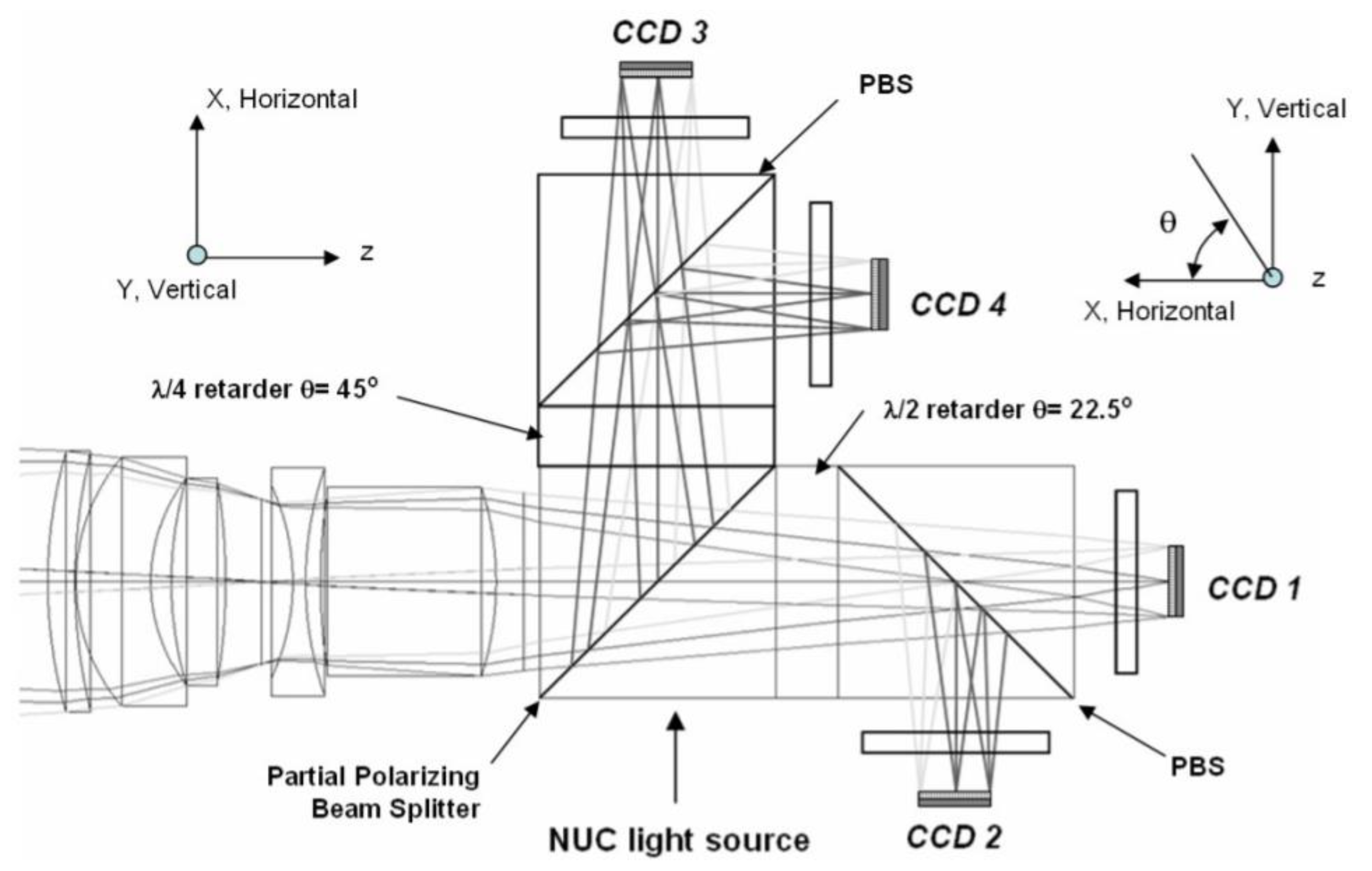
The fractional amplitude polarization imaging system uses beam splitter, polarized beam splitter or Wolston prism to divide the incident light into 3 to 4 channels of polarized beam. By combining the imaging lens and multiple imaging detectors, it forms multiple channels to acquire the intensity image of different polarization components of the same target scene. The target Stokes component graph is obtained by data reduction matrix. The fractional amplitude polarization imaging system has the advantages of good real-time performance and high energy utilization.
Azzam designed the first partial amplitude polarization measuring instrument, that is, through splitting prism, PBS (polarization splitting prism) and other functions, the scene radiation is divided into 4 polarized beams, imaging on 4 CCD, and then through the light intensity linear into electrical signals, output to the workstation for polarization analysis. On this basis, Azzam et al. also proposed a variety of amplitude-dividing devices, such as the 4-detector polarimeter [
22] based only on Fresnel’s law without using any common polarizing elements, grating diffraction [
23], optical fiber [
24], parallel glass plate [
25], etc., as amplitude-dividing devices. The fractional amplitude device divides incident light into multiple polarization channels in proportion to intensity, each of which only detects a specific polarization state [
14]. Fractional amplitude polarization imaging can be achieved by a variety of methods. For example, the light to be measured can be distributed into four polarization channels through multiple splitter prisms [
26] to achieve single-point polarization measurement or polarization imaging. The polarization splitting prism is the most basic amplitude-splitting device. The incident light is divided into two linear polarization states, such as horizontal and vertical polarization components, and the Stokes parameter S can be measured simultaneously 0, S1; The Stokes parameter S can be simultaneously measured by using two polarization splitting prisms with different orientation0, S1, S2; The incident beam can be divided into 4 beams by using 3 or more splitter elements, and the Stokes parameter S can be simultaneously measured 0, S1, S2, S3. As shown in
Figure 6 and
Figure 7, Schematic of Full Stokes Imaging Polarimeter by Pezzaniti J.L. et al. [
27] in 2009 and the polarization imaging schematic diagram based on fractional amplitude by Peinado et al. [
28] in 2013 are quoted.
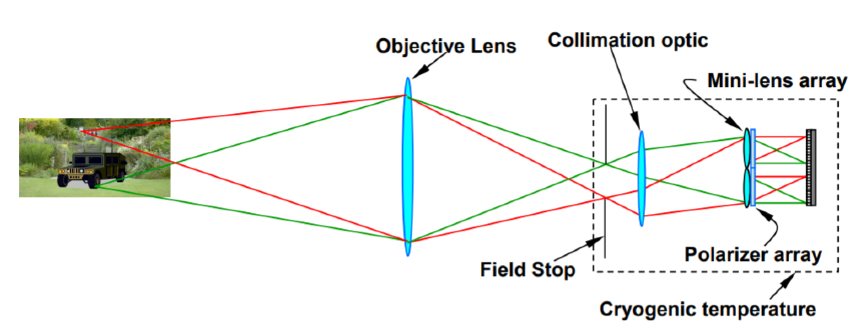
3.2.2. Split-Aperture Polarization Imaging
The split-aperture polarization imaging system is to divide the whole system into multiple split-aperture systems by the method of aperture segmentation. Each split-aperture system adopts different polarization elements, so that each split-aperture system can obtain intensity images of different polarization states. At the aperture of the system, four imaging lens arrays were placed off-axis to form four channels. In each channel, the polarization analyzer was placed to obtain the intensity map of polarization component, and the Stokes vector map obtained by computer processing was used. Four polarization channels share a preobjective lens, and the images of the four polarization channels can be imaged on a CCD through reasonable arrangement. By using an objective lens and an optical imaging system, image the different polarization states of the scene radiation on the same detector through the polarized optical elements, which not only realizes the simultaneous polarization imaging, but also ensures that the field of view of the four polarization channels is co-axial. The advantages of the split aperture simultaneous polarization imaging system are that there are no excessive splitter elements, the optical system is stable, simple, compact and convenient for data processing, and the disadvantage is the loss of spatial resolution [
14]. As shown in
Figure 8, the schematic diagram of simultaneous polarization imaging with split aperture and the polarization imaging effect are quoted [
29].
3.2.3. Split-Focal Plane Polarization Imaging
The focal plane system includes micropolarizing plate array linearly polarized camera and microwave plate array fully polarized camera [
30,
31,
32,
33,
34,
35,
36,
37,
38,
39,
40,
41]. Is similar to the color camera bayer filter array, the array polarized micro polaroid camera each pixel covers different azimuth polaroid, when was the scene of the shooting light intensity spatial frequency and polarization spatial frequency is low, the neighbor of the covered with four different directions of each of the pixels of polaroid receives the Stokes vector can be considered to be consistent, The four pixels are regarded as one polarization pixel, which has four polarization channels, and the linearly polarized part of Stokes vector can be solved.
With the development of Focal plane array (FPA) technology, it is possible to integrate micropolarized optical elements into FPA. One pixel of Focal plane can correspond to one micropolarized element to form a Focal plane simultaneous polarization imaging detector. Micropolarizations with different polarization directions are integrated in the four adjacent detector units, which can achieve single-exposure 4-polarization imaging without splitting. The focal plane polarization imaging system has the advantages of compact structure, small volume and high stability. However, each pixel corresponds to a polarization element, so the spatial resolution is low. Therefore, in the case of different polarization states, there is at least one pixel position matching error between each pixel. In 2018, Sony launched a polarization sensor IMX250 MZR [
42]. As shown in
Figure 9, each micropolarized plate has an anti-reflective layer and is placed between the microlens and the photodiode. This structure can minimize the crosstalk of polarized light in different directions.
4. Application of Stoker Vector Polarization Imaging
Compared with traditional detection technology, polarization imaging technology has incomparable advantages in the following aspects: one is when the target use camouflage coatings, camouflage net technology in disguise, such as polarization imaging technology can break through the limitations of traditional detector, are more likely to find the goal; Second, when the target radiation is weak and the background radiation is strong, it becomes difficult for the traditional detector to clearly distinguish the characteristics of the target from the background, and it is easier to highlight the target by using polarization imaging technology. Third, in the atmospheric environment, polarization imaging technology can increase the detection range under the conditions of smoke and fog, and polarization information has better retention than intensity scattering information.
With the increase in application demand and the rapid development of photoelectric technology, all Stokes polarization imaging technology has become a hot research topic at home and abroad, and a variety of all Stokes polarization imaging schemes based on Stokes vector have been proposed. The Stokes parameters obtained by these schemes have been increased from two to four, and the way of obtaining polarization graphs has been developed from successively acquiring four polarization graphs to simultaneously acquiring four polarization graphs at one time, which has gradually realized the detection of all polarization components and greatly improved the real-time performance.
In military application, the earlier and more common monitoring method is to obtain the radiation spectrum of the object, that is, two-dimensional gray image. However, even two different objects can be camouflaged to make the radiation spectrum the same, but the polarization information can represent the inherent properties of the object and is independent of the spectral information. In the case of complex background and camouflaged targets, polarization imaging detection can enhance the recognition of the target, which is conducive to the detection of relatively hidden targets. The special polarization state (circular polarization state) of some substances in a specific direction is helpful for underwater submarine search and tracking [
43,
44]. In the field of remote sensing ground object detection, according to the basic principle that different substances have different polarization information, polarization detection can obtain the distribution information of vegetation, minerals and other substances on the Earth, providing more abundant data for geological investigation, mineral exploration and vegetation protection, etc., which is more active in the field of gas detection and sea surface detection [
45,
46]. Polarization imaging technology can be used to more clearly record the physical structure and distribution inside the clouds and determine whether there are clouds and oil stains on the sea surface [
47,
48]. In the biomedical field, polarization is used to obtain the polarization information of relevant tissues before and after lesions, which is helpful for the diagnosis of cancer, burn and other diseases [
49,
50].
Image defogging has been a hot topic in target detection and automatic recognition, which has attracted extensive attention of researchers. The polarization imaging of split focal plane based on Stokes vector proposed a new method to improve the quality of defogging images. Yu Lei et al. proposed a polarization defogging method based on image fusion and adaptive adjustment algorithm in 2021 [
51]. A split-focal plane linear polarization camera (FLIR, BFS-U3-512P-C) was used to collect images with four different polarization directions, and then low-pass filtering was performed on the images to perform rough haze separation to reduce the adverse effects of noise. Secondly, the key parameters of the scattering model are estimated according to the filtered image, and a new transmittance image is obtained by image fusion technology to enhance the line-of-sight of the defogging image. Thirdly, these parameters are substituted into the scattering model to obtain the defogging image. Finally, in order to improve the visual effect of the image, an adaptive adjustment algorithm is used to adjust the light distribution of the image. Several fuzzy images were captured, and the conventional method and this scheme were used for defogging, and three evaluation indexes were used to quantitatively evaluate the defogging images. Experimental results show that this method can better solve the problems existing in the traditional method. This method cannot operate effectively under the condition of low DOP of background scattered light, reduce the adverse effects of haze, and ultimately enhance the visual effect and quantitative evaluation. The physical model of atmospheric scattering and Polarimetric imaging proposed in [
51], as shown in
Figure 10.
Reference [
8] proposed a method to suppress scattering by Stokes vector polarization, using the total radiation polarization information of the gradient image pixel level prior knowledge to build a global model, the method can solve the target image of a light polarization degree of global change, achieve the goal calculated polarization of the light with each pixel in the scene, to effectively restore the details of the underwater scene. Experimental results show that the global pixel calculation method has obvious effect on underwater scene image details restoration, the influence of backscattered light on underwater imaging is effectively suppressed, image contrast is significantly improved, and clear underwater vision is achieved. The underwater imaging model in reference [
8] is quoted, as shown in
Figure 11.
5. Conclusions
Because the human eye is sensitive to the intensity and wavelength of light, human have the earliest and most understanding of these two properties of light and have developed various optical imaging and spectral measurement equipment. At the same time, the human eye is not sensitive to the polarization properties of light, so the research on the polarization properties of light started late compared with the research of light intensity and wavelength. However, with the progress of technology and the development of society, polarization imaging technology is showing its unique advantages compared with traditional imaging technology centering on the attributes of light intensity, phase and wavelength. Polarization imaging technology has shown potential applications in the fields of Marine microalgae identification, biomedicine, modern military and industrial detection, de-scattering imaging, navigation and so on. At present, from the perspective of polarization information acquisition, polarization imaging has developed from “large size and complex structure” to “light and small size, integrated and modular”, and from “narrow band” to “wide band and full band”. However, polarization imaging technology also faces some challenges, such as the polarization characteristics of the target and polarization transmission characteristics need to be further deepened, and so on, which is the direction of future efforts. In this paper, on the basis of the principle of polarization imaging of the Stokes vector according to the Stokes vector method for different polarization modulation, respectively introduces the non-simultaneous polarization imaging and at the same time the implementation of polarization imaging, boost the application of polarization imaging methods, promote the research and development of polarization imaging, predictably with the continuous development of polarizing technology, Polarization imaging technology will become the next breakthrough of optical technology with its unique attribute advantages, which is worth the attention of researchers.


 ,
, 


