1. Introduction
In the recent decade, the dramatic proliferation of wireless devices has offered us convenience in most aspects of our daily life. These wireless devices (e.g., smart phones and ZigBee sensors) are deployed densely in typical scenarios such as offices, hospitals, etc. However, coexistence of heterogeneous devices equipped with fundamentally different physical-layer protocols would cause severe cross-technology interference (CTI) [
1,
2] since these devices work on the shared ISM band.
Cross-technology interference is a double-bladed sword. On one hand, it declines the performance of wireless communication or even interrupts ongoing transmission. An extensive number of researches have focused on coordination of heterogeneous devices to avoid CTI [
3,
4] and mitigate the effects of CTI on data transmission [
5,
6]. On the other hand, it creates opportunities for cross-technology communication (CTC) via sensing the energy of received signal. Esense [
1], HoWiES [
7], FreeBee [
8], and LongBee [
9] were proposed a CTC frameworks to enable wireless devices with different physical layers to communicate through modulating CTC bits over the length of packets, number of consecutive packets, and packet interval. To significantly improve the throughput of CTC, WEBee [
10], SymBee [
11], X-MIMO [
12], and SDR-lite [
13] were proposed to enable high-throughput CTC between WiFi and ZigBee via exploring the specific physical-layer information of WiFi and ZigBee. Although SymBee [
11] has already enabled 31 Kbps high-throughput cross-technology communication from ZigBee to WiFi, it sacrifices the existing ZigBee traffic, resulting in the interruption of ZigBee communication. Hence, to reduce the large overhead caused by CTC, a high-throughput ZigBee-to-WiFi CTC, which is transparent to ongoing ZigBee communication, is needed.
In order to achieve high-throughput ZigBee to WiFi CTC, we still face many critical challenges as follows. First, ZigBee and WiFi have totally different packet formats. A ZigBee preamble without modification cannot pass the packet detection module of WiFi. Second, the bandwidth of WiFi is much wider than that of ZigBee. It means that there will be information loss when ZigBee node send the packet to WiFi. Third, ZigBee and WiFi adopt different modulation schemes. It is not possinle to directly decode a ZigBee signal on WiFi.
In orer to address the above challenges, we propose a cross-technology communication framework to improve the throughput of ZigBee-to-WiFi communication without introducing any additional burden to the existing ZigBee network. In this paper, we modify some of ZigBee chips to carry CTC messages and, theoretically, this modification would be tolerated by ZigBee communication because of high redundancy in the ZigBee protocol. At the WiFi receiver, the Schmidl–Cox algorithm is applied to detect whether the received signal is WiFi or not in preamble detection [
14]. Even ZigBee signal could not pass WiFi preamble detection, we can obtain some useful information—for example, phase offset—to demodulate CTC messages in the WiFi physical layer. In detail, ZigBee signal would generate a strong pattern at the phase offset value calculated in WiFi preamble detection. In our design, we can generate different patterns (extending the duration of stable phase offset values) in WiFi preamble detection through modifying ZigBee chips. We implement our design on USRP/GNURadio platform to explore the feasibility of our scheme. The experiments show that the throughput of our CTC design is 31.25 Kbps, while the ZigBee packet error rate is ≤5%, which means that our design is transparent to ZigBee communication. The main contributions of this paper are listed as follows:
We investigate the impact of ZigBee signal on WiFi preamble detection. The preliminary experiment shows that ZigBee signal generates the stable periods in preamble detection, which has a strong pattern and is different with noise.
We propose our chip-level side channel design to embed the CTC bits. This method effectively modulates/demodulates CTC messages while maintaining transparency to the ongoing ZigBee communication.
Last but not least, we implement our design on USRP N210 with GNURadio and evaluate the performance in practical environments. The experimental results indicate that our design is compatible with ZigBee devices and throughput of this CTC can reach up 1000 times higher than the state-of-the-art CTC design.
The rest of this paper is organized as follows:
Section 2 introduces some background and motivation. In
Section 3, we present our main design. Our experiment results and some discussions are shown in
Section 4.
Section 5 shows the related work. The Discussion is stated in
Section 6. At last,
Section 7 concludes this paper.
2. Preliminaries
Since our design exploits the physical-layer of ZigBee and WiFi, we briefly review some background knowledge of the physical layer architecture of ZigBee and WiFi preamble detection in this section. Then, we will discuss how the ZigBee signal impacts on WiFi preamble detection.
2.1. Background
2.1.1. ZigBee Physical Layer
IEEE 802.15.4 standard [
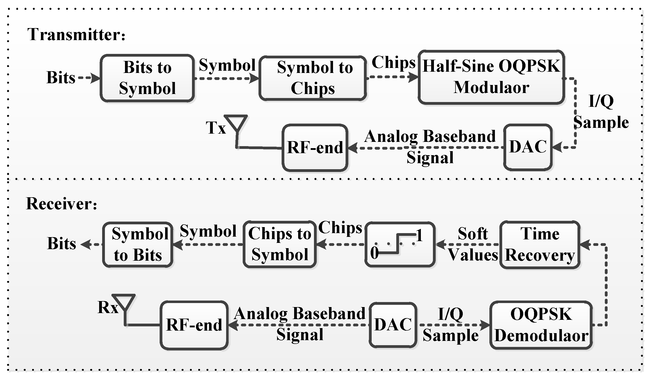
15] specifies how a ZigBee device operates to transmit and receive data. Even though ZigBee devices can work on both 2.4 GHz (worldwide), 900 MHz, and 868 MHz ISM bands, this paper focuses on 2.4 GHz, which is the most common ZigBee frequency band. On 2.4 GHz, there are sixteen ZigBee channels with a bandwidth of 2 MHz. The throughput of ZigBee is 250 kbps. The architectures of ZigBee transmitter and receiver are illustrated in
Figure 1.
At a ZigBee sender, every four bits are assembled into one symbol. For example, bits “1001” is assembled to be symbol ‘9’. Each symbol is spread into 32 chips according to
Table 1. Later, each chip (0/1) is modulated by Offset Quadrature Phase-Shift Keying (O-QPSK). Specifically, in half-sine O-QPSK modulator, chips with even index are modulated into I-phase while chips with odd index are modulated into Q-phase, as illustrated in
Figure 2. Each chip consists of 4 samples, which form a half-sine waveform. The duration of each chip is 1 μs and the chip rate of ZigBee is 2 Mchips/s. Moreover, there is a half-sine time offset (0.5 μs) between Q-phase and I-phase. Then, an digital-to-analog converter (DAC) converts I/Q samples into analog signal, which is further sent out by radio front-end. Finally, every ZigBee symbol is transmitted into air as a 16 μs signal.
At the ZigBee receiver, an analog-to digital converter (ADC) converts the baseband signal into I/Q samples at a sampling rate of 4 M/s. Hence, every ZigBee symbol has 64 samples. Quadrature demodulator outputs phase offset between two consecutive samples. The time recovery block would compensate sampling offset and decimates 64 phase offset values into 32 phase offset values, which are also called soft values. Chip is determined according to the sign of soft value. If the soft value is above zero, the corresponding ZigBee chip is decided to be ‘1’; otherwise, it is ‘0’. The distance between the received 32 chips and ideal chip sequence is called Hamming distance. Symbol and bits are determined by mapping the received 32 chips into the IEEE 802.15.4 chips sequence with minimum Hamming distance.
2.1.2. WiFi Preamble Detection
The WiFi signal is detected by WiFi preamble detection, which is designed to detect the WiFi signal and trigger the subsequent WiFi decoding process. In
Figure 3, a WiFi preamble consists of ten repeated short training symbols (STS) and two repeated long training symbols (LTS). The duration of STS and LTS are 0.8 μs and 3.2 μs, respectively. Essentially, if ten repeated signals are detected, this signal is determined to be the WiFi preamble.
The most common applied WiFi preamble detection algorithm is the Schmidl–Cox algorithm, which has two main functions: WiFi preamble detection and carrier frequency offset estimation, as shown in
Figure 4. Sampling rate of a WiFi device is 20 M/s and duration between two consecutive samples is 0.05 μs.
denotes amplitude of the
sample. As illustrated in
Figure 3, duration of a short training symbol is 0.8 μs, which also equals to the duration of 16 samples [
16]. Hence,
if
and
are sampled on WiFi preamble.
Essentially, Schmidl–Cox computes the phase offset between and . If the received signal is WiFi preamble, . In practice, even though WiFi sender and WiFi receiver are working on same channel, center frequency of sender and receiver are not the same due to drift of oscillators. Then, is a bit higher than zero.
2.2. How ZigBee Signal Impacts WiFi Preamble Detection
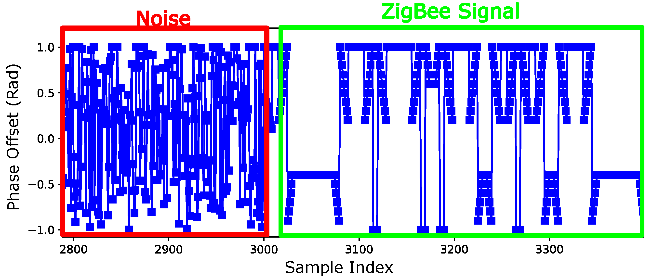
In the WiFi preamble detection, if the received signal is a ZigBee signal, the phase offset would be different from noise and WiFi preamble. In
Figure 5, the left part in red rectangle is the phase offset of noise and the right part in green rectangle is phase offset of a ZigBee signal. Even though ZigBee signal is totally different from WiFi preamble, there is still a strong pattern in the phase offset values, as shown in
Figure 5. Despite the fluctuation, there are still some stable periods in the phase offset values. Now, we can prove that the values of these stable phase offset are
and
.
Theorem 1. When WiFi preamble detection receives a ZigBee signal, the values of the phase offset in the stable periods are π and .
Proof. In this paper, we use
to denote the
sample of raw ZigBee signal and
to denote the difference of center frequency of ZigBee sender and WiFi receiver. Further,
stands for duration of sample at WiFi receiver, which is equal to 0.05 μs. Then, we have
. We also use
to denote the multiplication of
and conjugate of
:
where
is the conjugate of
. The phase offset of ZigBee signals at WiFi receiver is
. Since
is a constant complex value and would not affect the fluctuation of
, whether
is stable or not is determined by
. Moreover,
.
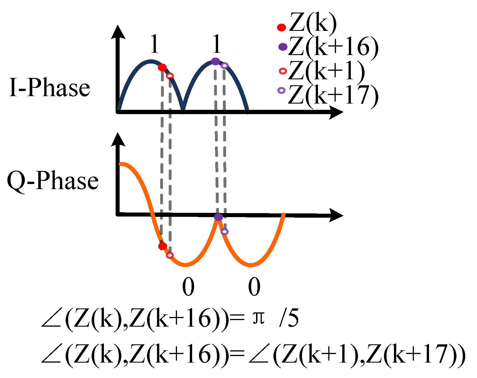
When two consecutive chips on I-phase are the same and two consecutive chips on Q-phase are the same, there would be a stable period. For instance, as shown in
Figure 6, chips on I-phase are two ‘1’s and chips on Q-phase are two ‘0’s,
is equal to
. When two consecutive chips on I-phase are different and two consecutive chips on Q-phase are different, there also exists a stable period. For instance, as shown in
Figure 7, chips on I-phase are ‘1’ and ‘0’ and chips on Q-phase are ‘1’ and ‘0’,
is equal to
. Hence, after adding
,
equals to
and
. In other cases, there would not be a stable period. □
3. Framework Design
In this section, we introduce our main design based on the analysis about the pattern of ZigBee signal observed at WiFi preamble detection. Then, we present our CTC modulation/demodulation approaches.
3.1. Framework Overview
As illustrated in
Figure 8, our intuitive idea is that we make the ZigBee sender modify some chips within one symbol to modulate CTC messages and these modification can be detected in WiFi preamble detection. Theoretically, ZigBee devices transmit 4 bits with a 32-bit chips sequence that consists of a high redundancy. Based on the results in [
17], if we do not modify too many chips, ZigBee receiver could still decode ZigBee data correctly. Then, the question is how to modify ZigBee chips to generate a detectable pattern in WiFi preamble detection.
According to our analysis in
Section 2.2, if the consecutive chips on I-phase and Q-Phase form a continuous sine wave, the phase offset value at WiFi preamble detection is stable at
. Then, if we could modify some of the ZigBee chips, we would be able to extend the duration of the stable phase pattern at WiFi preamble detection. Hence, we control ZigBee sender to generate a longer sinusoidal waveform, which induces longer stable phase offset values at WiFi preamble detection. The modified ZigBee chips would be tolerated at the ZigBee receiver; hence, the communication between ZigBee devices would not be affected severely. Meanwhile, the sinusoidal waveform (generated by modified chips) can be detected in WiFi preamble detection and the carried CTC data would be demodulated by the WiFi device.
3.1.1. Extending Sinusoidal Waveform in ZigBee
In half-sine O-QPSK modulator, chips with even index are placed on I-phase while chips with odd index are placed on Q-phase. ZigBee devices use Direct digital synthesizer (DDS) to generate the waveform in half-sine pulse shaping. Specifically, DDS would generate 4 samples: 0,
,
,
, which are the envelop of a half-sine waveform. Chip “0” would be shaped into a low half-sine wave through multiplication of −1 and these 4 samples. Chip “1” would be shaped into an up half-sine waveform by multiplying 1 and these 4 samples. Therefore, manipulating the generated waveform equals to control the chips. To extend sinusoidal waveform, as illustrated in
Figure 9, we flip four red marked chips by switching the chip value. Finally, our modification leads to a 6.5 μs sinusoidal Wave at the ZigBee sender.
3.1.2. Detecting the Extended Sinusoidal Waveform at WiFi
If the received signal is a continuous sinusoidal wave, as analyzed in
Section 2.2, the corresponding phase offset value should be stable at
. Then, the extended sinusoidal waveform would induce longer stable phase offset values at WiFi preamble detection. Since the duration of the extended sinusoidal waveform is much longer than the sinusoidal waveform in the original ZigBee chips, we can recognize the extended sinusoidal waveform without checking the phase offset value. To detect the extended sinusoidal waveform at WiFi, we only need to detect whether there exists the certain amount of stable phase offset value or not. For example, there exists the 6.5 μs stable phase offset value; this indicates that the extended sinusoidal waveform, which is generated by the modification in
Figure 9, is detected in the WiFi preamble detection. Specifically, if there are
consecutive stable phase offset samples detected, the received signal is determined to be the extended sinusoidal wave.
We note that the 6.5 is specific to the modification in
Figure 9. In general, we could modify more chips to achieve an even longer extended sinusoidal wave (We could modify 6 chips; the corresponding evaluation results are shown in
Section 4.4). If we use
to denote the duration of the extended sinusoidal wave, the number of consecutive stable phase offset samples we need for detecting the extended sinusoidal wave is derived by the following equation:
where
represents the WiFi sampling rate. The value of
supported by commodity WiFi devices includes 20 M/s and 40 M/s. We have already shown that we are able to generate the extended sinusoidal waveform at CTC sender (ZigBee) side and detect the extended sinusoidal waveform at CTC receiver (WiFi) side. In the following subsection, we show our CTC modulation/demodulation approach.
3.2. On–OFF Keying-Based Modulation/Demodulation
3.2.1. Modulation
Intuitively, On–Off keying modulates CTC bit ‘1’/‘0’ by modifying chips to be the extended sinusoidal waveform or not. In other words, if we want to modulate “0”, we do not need to modify the chips. In this case, however, we cannot distinguish CTC bit “0” with the case where there are no CTC data. If we employ On–Off keying to modulate CTC bits directly and there are no CTC data, we would treat this ZigBee signal as CTC bit “0”. Therefore, for each CTC bit, we need a reference point to inform the CTC receiver that the next ZigBee symbol contains CTC bit.
Our modulation scheme can be illustrated in
Figure 10. In the first symbol, there is an extended sinusoidal waveform in the first ZigBee symbol indicating that this symbol is a reference symbol and next symbol contains CTC bit. Since there is no extended sinusoidal waveform detected in the second ZigBee symbol, the second ZigBee symbol is determined to be CTC bit ‘0’. On the third chip of second symbol, there is an extended sinusoidal waveform indicating the reference. Since there is an extended sinusoidal waveform in the fourth ZigBee symbol, the fourth ZigBee symbol represents the CTC bit “1”.
3.2.2. Demodulation
In WiFi preamble detection, we can obtain the phase offset values and count the number of stable samples every 320 samples (i.e., length of a ZigBee symbol and 16 μs). If the number of stable samples equals to , there should be an extended sinusoidal waveform in this 16 microseconds. Therefore, if WiFi preamble detection finds that there exists an extended sinusoidal waveform in the received signal, it would know that the next 320 samples contain a CTC bit. The CTC bit would be determined by detecting whether there exists the extended sinusoidal waveform in the next 320 samples or not.
Based on this modulation/demodulation approach, we can transmit 1 CTC bit within 2 ZigBee symbols while ZigBee communication transmits 4 bits within 1 ZigBee symbol. Hence, the throughput of our CTC approach should be
the throughput of ZigBee, i.e., 31.25 kbps, which is 1000 times the throughput of FreeBee [
8].
4. Evaluation
In this section, we conduct extensive experiments to evaluate the performance of our design.
4.1. Experiment Setup
We implemented our design on the USRP N210 [
18] running GNU Radio 3.7.9 [
19]. For comparison, we also implemented the state-of-the-art work Symbee on USRP platform. Symbee yields unique patterns with specific ZigBee symbols when WiFi conducts idle listening. We implemented our modulation approach on USRP based on IEEE 802.15.4 implementation by Bastibl [
19]. We use MicaZ nodes as ZigBee receiver. We also implemented our demodulation approach based on the Schmidl–Cox algorithm on USRP as WiFi preamble detection. We take IEEE 802.11 g/n on the WiFi receiver. Unless otherwise specified, the sending channel is set to channel 23 while channel 11 is set as the receiving WiFi channel. The payload covers all the 16 ZigBee symbols and the number of each symbol is equal.
The experiment setup is shown in
Figure 11. The CTC ZigBee sender sends out ZigBee signal attached with CTC data while CTC WiFi receiver receives this signal and decodes CTC data. Meanwhile, ZigBee receiver also receives ZigBee data regardless of the modified ZigBee chips.
4.2. Evaluation Metrics
We take the CTC symbol Accepted Ratio (CTC-SAR) and ZigBee Packet Accepted Ratio (ZigBee-PAR) as the key metrics to evaluate the performance of our design. CTC-SAR is the accepted ratio of the number of correct demodulated CTC symbols to the number of CTC symbols; it is calculated as follows:
ZigBee-PAR is the accepted ratio of the number of correct ZigBee packets to the number of all the receiving ZigBee packets. The packet will be lost if it fails the CRC check, even if only one symbol is corrupted. It is calculated as follows:
4.3. Phase Offset of Modified ZigBee Signal in WiFi Preamble Detection
In this experiment, we set the number of modified chips to 6 and the results are recorded in
Figure 12. In this figure, phase offset of the extended sinusoidal waveform is around
with standard variance of 0.07. These fluctuations are caused by noise and multipath fading.
4.4. CTC Symbol Accepted Ratio
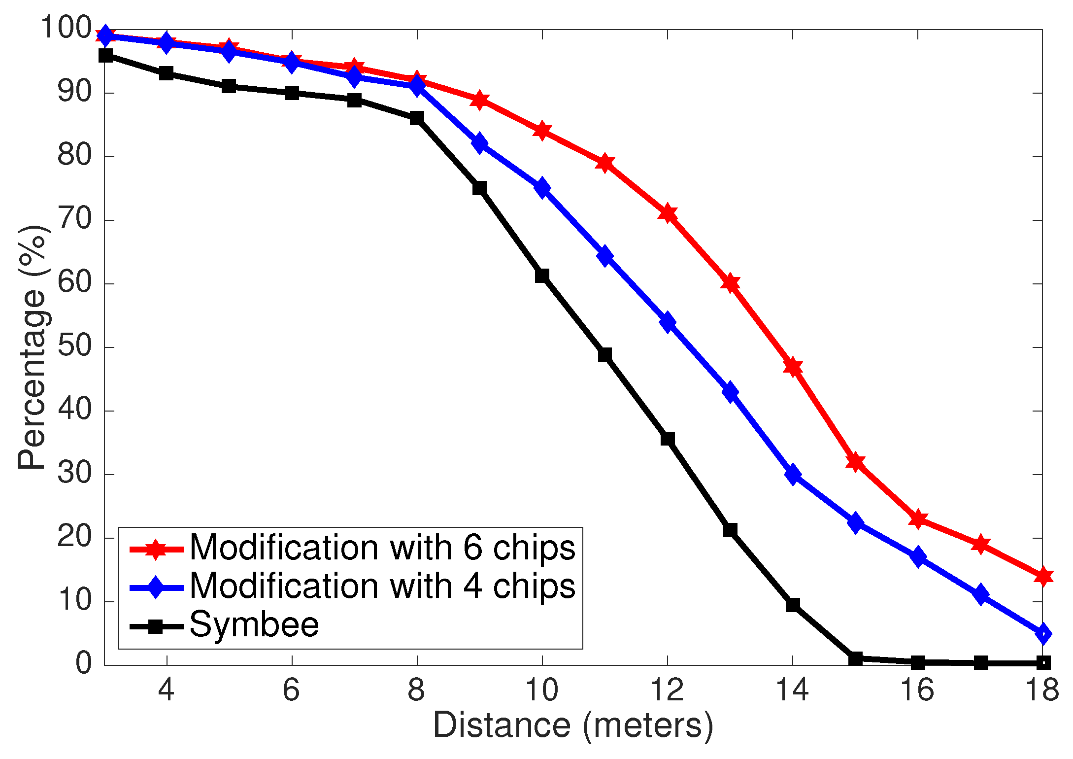
We compare the CTC-SAR. We set the number of modified chips in our design as 4 and 6. In this experiment, we collect CTC bits at WiFi receiver for 10 min and then move CTC ZigBee sender 1 more meter away from the WiFi receiver. The comparison result is shown in
Figure 13. This figure shows that the CTC bits accepted ratio of our design is higher than that of Symbee, especially when the distance is more than 8 m. From the figure, we can also find out that as more chips are modified, our CTC design becomes more robust. Moreover, if the distance between sender and receiver is too far, ZigBee signal would be distorted at the CTC receiver side dramatically. Hence, the bits accepted ratio of CTC drops if the CTC receiver is too far.
4.5. Transparency
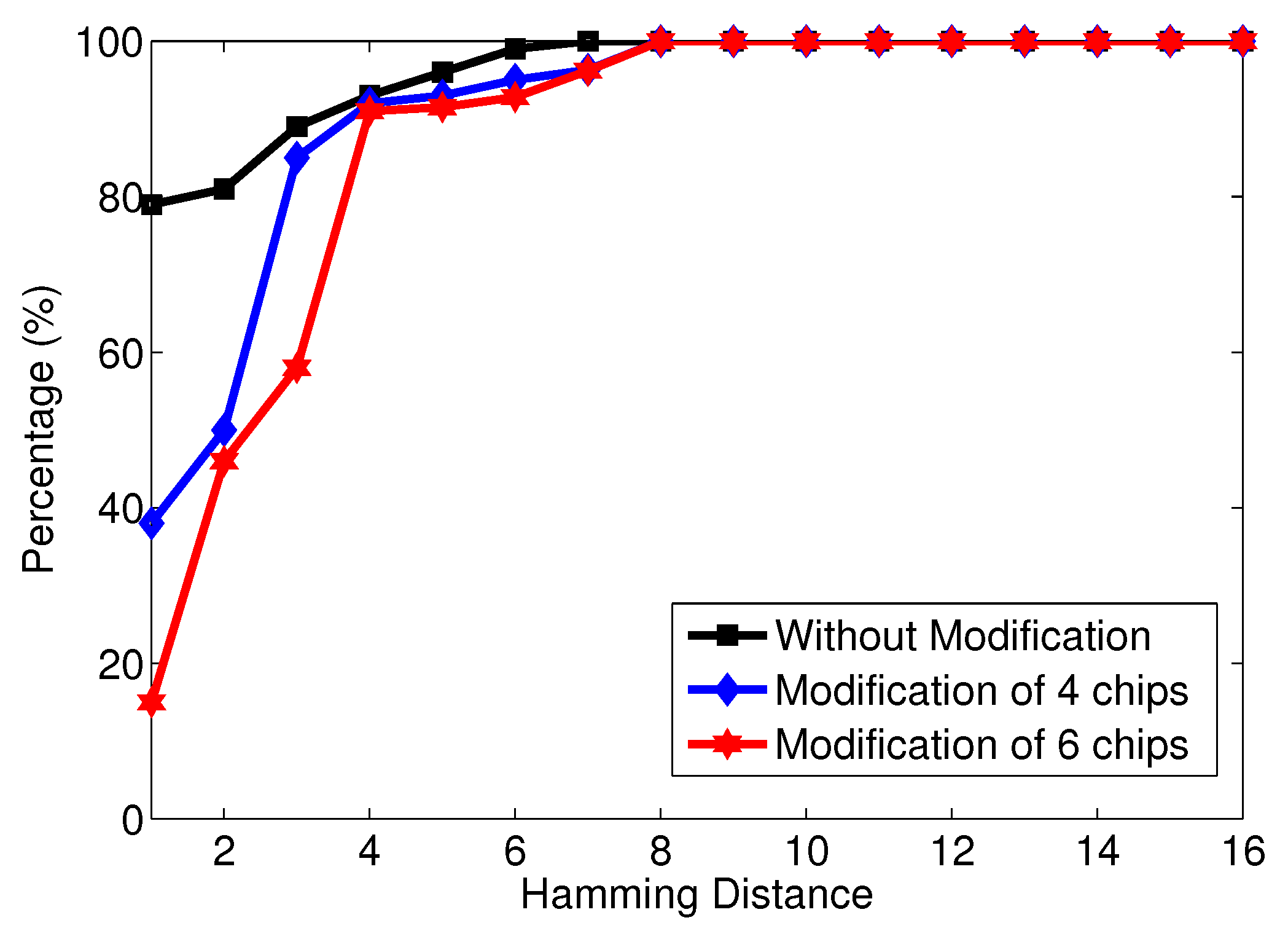
This experiment aims at showing that our design would not affect ZigBee communication too much. After modifying some of the ZigBee chips, the Hamming distance would increase and the ZigBee packets accepted ratio would decrease. As displayed in
Figure 14, our design has much better performance in the ZigBee-PAR than Symbee. As the distance increases, the performance gap becomes more pronounced. At the same time, the differences among ZigBee packets accepted ratio of three settings are not too significant when the distance between ZigBee CTC sender and WiFi CTC receiver is less than 10 m. As the distance increases, the more ZigBee bits could not be demodulated correctly due to error caused by ZigBee chips modification. More specifically, the cumulative distribution function (CDF) of Hamming distance when the distance is 3 m is plotted in
Figure 15. As we can see, the Hamming distance increases as more chips are modified. However, if sender and receiver are not located further than 10 m, our design is transparent to the ZigBee communication.
5. Related Work
Esense [
1] first proposed a CTC framework to enable wireless devices with different physical layers to communicate with each other through modulating the length of packets. HoWiES [
7] is aimed at saving WiFi energy with assistance from ZigBee-modulated CTC messages through a number of consecutive packets. WIDE [
20] utilizes digital emulation to reduce emulation errors from WiFi to ZigBee. FreeBee [
8] enables communications among WiFi, ZigBee, and Bluetooth. The recent CTC designs, including WEBee [
10] and SymBee [
11], achieve 250 Kbps and 31 Kbps throughput from WiFi to ZigBee and ZigBee to WiFi, respectively. LongBee [
9] is another improved CTC work of WEBee. LongBee extends the communication range of CTC to support long-range IoT applications. X-MIMO [
12] supports MIMO for cross-technology communication. SDR-lite [
13] supports ZigBee to WiFi high-throughput CTC. However, SDR-lite is destructive to the WiFi communication. Ref. [
2] is proposed to support the MAC layer for CTC. Despite the good performance, they need to sacrifice ongoing WiFi and ZigBee traffic, which is destructive. C-LQI [
21] proposes a new link metric and a joint link model that considers both the emulation error and the channel distortion. Based on the link model, a lightweight approach is proposed to estimate the quality of the CTC link. CoWBee [
22] proposes a network-layer spectrum allocation technique deployed in existing WiFi infrastructure from WiFi to ZigBee. In this paper, our design overcomes the low-throughput and transparency issue by creating a chip-level side channel for ZigBee-to-WiFi CTC.
6. Discussion
With the proliferation of IoT devices in all kinds of scenarios, we may foresee the ever-increasing needs of CTC in wireless systems. Our design has shown its good performance as a software implementation on USRP, it will have tremendous potential on future hardware implementation of CTC WiFi devices. Note that in our design, most of the standard WiFi modules are reused. According to the scheme of our design, WiFi devices obtain the new ability of CTC, with limited modification, while all the properties and functions of a WiFi device are completely preserved.
One of the biggest drawbacks in our work is that the WiFi module completes the most calculations, which consume the resources. The decoding process of WiFi packets includes short preamble detection, long preamble detection, FFT, QAM demapping, and deinterleaving. The decoding process of our design is relatively simple compared with the decoding process of WiFi packets. Moreover, our design does not interrupt the ongoing ZigBee communication. It means that cross-technology communication can parallel with standard ongoing communications.
7. Conclusions
This paper proposes a novel ZigBee-to-WiFi cross-technology communication approach with the throughput 1000 times greater than the state-of-the-art CTC design. The proposed CTC design is transparent to the ongoing ZigBee communication. The existing CTC designs either are too slow or need to interrupt the ongoing ZigBee communication. This paper investigates how the ZigBee signal impacts the WiFi preamble detection and proposes a chip-level CTC design based on modifying some ZigBee chips to extend the sinusoidal waveform in the ZigBee signal. Moreover, the principle and analysis of this design was presented. Finally, the evaluation shows that the performance of this design can outperform all current CTC approaches significantly despite the fact that the CTC communication range should be shorter than 10 m.
7.1. Theoretical Implications
Our study has two points in the theoretical implications. One point is that considering the state-of-the-art design cannot be compatible with the ongoing communication, on the theoretical level, future studies can explore and utilize the redundancy of the packets to maintain the ongoing communication.
The other point is that the feature of ZigBee signal in the WiFi module can be utilized in the process of many CTCs in heterogeneous wireless networks (HWNs). This means that future research can utilize the results of our study to distinguish the different kinds of signal from noise in the WiFi module.
7.2. Practical Implications
The results of our study are eminently practical. Our design takes the feature of ZigBee to communicate with WiFi-embedded devices directly without any gateways. Therefore, it can be easily deployed in the IoT environment. At the same time, most of the computing is processed on the WiFi device. This means that there is not too much extra cost on the energy consumption of ZigBee nodes. Our design does not sacrifice the existing ZigBee communication to support CTC because it is transparent to the ongoing ZigBee communication. As mentioned above, our study has great prospects in heterogeneous wireless communication in IoT.
7.3. Limitations and Future Research
Our study can solve the problem of interrupting the ZigBee communication when high-throughput ZigBee-to-WiFi CTC communication is guaranteed. However, it still has some points that can be improved. When the distance between the sender and receiver become far, the bit accepted ratio of CTC drops fast. Therefore, this distance will directly affect the performance of our design. Moreover, our study only considers CTC communication from ZigBee to WiFi while CTC from Bluetooth to WiFi is also worthy of study.
Future IoT will connect billions of backpack computing devices and support cross-technology communication between them [
23]. The key challenge of designing IoT is how to reduce the negative effects of Cross Technology Interference and experimentally utilize the CTI [
24]. In response to this challenge, cross-technology communication is proposed that enables direct communication among different kinds of nodes [
25]. Due to the near-zero cost connection among heterogeneous devices, CTC has attracted a lot of interest. Nevertheless, there exist many unresolved issues in future to meet the application need. The recent research on CTC that has brought new opportunities while maintaining full compatibility with commodity devices still has several challenges. Moreover, there is room to further improve the channel usage efficiency with channel coordination between different kinds of devices.
Author Contributions
C.F. wrote the manuscript; T.X. collected the data; C.F. edited and revised the manuscript; T.X. drew the figures; C.F. designed research methods; T.X. analyzed the data. All authors have read and agreed to the published version of the manuscript.
Funding
This research was supported by the National Natural Science Foundation of China 61902059 and the Fundamental Research Funds for the Central Universities 2572019BH02.
Institutional Review Board Statement
Not applicable.
Informed Consent Statement
Not applicable.
Conflicts of Interest
The authors declare no conflict of interest. The funders had no role in the design of the study; in the collection, analyses, or interpretation of data; in the writing of the manuscript, or in the decision to publish the results.
References
- Chebrolu, K.; Dhekne, A. Esense: Communication through energy sensing. In Proceedings of the 15th Annual International Conference on Mobile Computing and Networking, Beijing, China, 20–25 September 2009; pp. 85–96. [Google Scholar]
- Wang, S.; Yin, Z.; Wang, S.; Chen, Y.; Li, Z.; Kim, S.M.; He, T. Networking Support for Bidirectional Cross-Technology Communication. IEEE Trans. Mob. Comput. 2019, 20, 204–216. [Google Scholar] [CrossRef]
- Zhang, X.; Shin, K.G. Cooperative carrier signaling: Harmonizing coexisting WPAN and WLAN devices. IEEE/ACM Trans. Netw. 2012, 21, 426–439. [Google Scholar] [CrossRef]
- Chae, Y.; Wang, S.; Kim, S.M. Exploiting wifi guard band for safeguarded ZigBee. In Proceedings of the 16th ACM Conference on Embedded Networked Sensor Systems, Shenzhen, China, 4–7 November 2018; pp. 172–184. [Google Scholar]
- Yubo, Y.; Panlong, Y.; Xiangyang, L.; Yue, T.; Lan, Z.; Lizhao, Y. ZIMO: Building cross-technology MIMO to harmonize ZigBee smog with WiFi flash without intervention. In Proceedings of the 19th Annual International Conference on Mobile Computing & Networking, Miami, FL, USA, 30 September–4 October 2013; pp. 465–476. [Google Scholar]
- Hithnawi, A.; Li, S.; Shafagh, H.; Gross, J.; Duquennoy, S. CrossZig: Combating Cross-Technology Interference in Low-power Wireless Networks. In Proceedings of the 2016 15th ACM/IEEE International Conference on Information Processing in Sensor Networks (IPSN), Vienna, Austria, 11–14 April 2016; pp. 1–12. [Google Scholar]
- Zhang, Y.; Li, Q. HoWiES: A holistic approach to ZigBee assisted WiFi energy savings in mobile devices. In Proceedings of the 2013 Proceedings IEEE INFOCOM, Turin, Italy, 14–19 April 2013; pp. 1366–1374. [Google Scholar]
- Kim, S.M.; He, T. FreeBee: Cross-technology communication via free side-channel. In Proceedings of the 21st Annual International Conference on Mobile Computing and Networking, Paris, France, 7–11 September 2015; pp. 317–330. [Google Scholar]
- Li, Z.; He, T. LongBee: Enabling Long-Range Cross-Technology Communication. In Proceedings of the IEEE INFOCOM 2018—IEEE Conference on Computer Communications, Honolulu, HI, USA, 15–19 April 2018; pp. 162–170. [Google Scholar] [CrossRef]
- Li, Z.; He, T. Webee: Physical-layer cross-technology communication via emulation. In Proceedings of the 23rd Annual International Conference on Mobile Computing and Networking, Snowbird, UT, USA, 16–20 October 2017; pp. 2–14. [Google Scholar]
- Wang, S.; Kim, S.M.; He, T. Symbol-level cross-technology communication via payload encoding. In Proceedings of the 2018 IEEE 38th International Conference on Distributed Computing Systems (ICDCS), Vienna, Austria, 2–5 July 2018; pp. 500–510. [Google Scholar]
- Wang, S.; Jeong, W.; Jung, J.; Kim, S.M. X-MIMO: Cross-technology multi-user MIMO. In Proceedings of the 18th Conference on Embedded Networked Sensor Systems, Virtual Event, 16–19 November 2020; pp. 218–231. [Google Scholar]
- Jeong, W.; Jung, J.; Wang, Y.; Wang, S.; Yang, S.; Yan, Q.; Yi, Y.; Kim, S.M. SDR receiver using commodity wifi via physical-layer signal reconstruction. In Proceedings of the 26th Annual International Conference on Mobile Computing and Networking, London, UK, 21–25 September 2020; pp. 1–14. [Google Scholar]
- Schmidl, T.M.; Cox, D.C. Robust frequency and timing synchronization for OFDM. IEEE Trans. Commun. 1997, 45, 1613–1621. [Google Scholar] [CrossRef] [Green Version]
- IEEE 802.15.4 Protocol. Available online: http://standards.ieee.org/getieee802/download/802.15.4-2015.pdf (accessed on 1 April 2021).
- IEEE 802.11 Protocol. Available online: http://standards.ieee.org/getieee802/download/802.11-2012.pdf (accessed on 1 April 2021).
- Wu, K.; Tan, H.; Liu, Y.; Zhang, J.; Zhang, Q.; Ni, L.M. Side channel: Bits over interference. IEEE Trans. Mob. Comput. 2011, 11, 1317–1330. [Google Scholar] [CrossRef]
- USRP N210. Available online: https://www.ettus.com/product/details/UN210-KIT (accessed on 15 May 2020).
- Implementation of IEEE 802.15.4 Protocol on USRP. Available online: https://github.com/bastibl/gr-ieee802-15-4 (accessed on 15 May 2020).
- He, Y.; Guo, X.; Zhang, J.; Jiang, H. WIDE: Physical-Level CTC via Digital Emulation. IEEE/ACM Trans. Netw. 2021, 29, 1567–1579. [Google Scholar] [CrossRef]
- Zhang, J.; Guo, X.; Jiang, H.; Zheng, X.; He, Y. Link Quality Estimation of Cross-Technology Communication: The Case with Physical-Level Emulation. ACM Trans. Sens. Netw. (TOSN) 2021, 18, 1–20. [Google Scholar] [CrossRef]
- Gao, D.; Wang, L.; Hu, B. Spectrum Efficient Communication for Heterogeneous IoT Networks. IEEE Trans. Netw. Sci. Eng. 2022. [Google Scholar] [CrossRef]
- Saura, J.R.; Palacios-Marques, D.; Ribeiro-Soriano, D. Exploring the boundaries of open innovation: Evidence from social media mining. Technovation 2022, 102447. [Google Scholar] [CrossRef]
- Razzaque, A.; Eldabi, T.; Jalal, A. Physician virtual community and medical decision making: Mediating role of knowledge sharing. J. Enterp. Inf. Manag. 2013, 26, 500–515. [Google Scholar] [CrossRef]
- Saura, J.; Ribeiro-Soriano, D.; Saldana, P. Exploring the challenges of remote work on Twitter users’ sentiments: From digital technology development to a post-pandemic era. J. Bus. Res. 2022, 142, 242–254. [Google Scholar] [CrossRef]
| Publisher’s Note: MDPI stays neutral with regard to jurisdictional claims in published maps and institutional affiliations. |
© 2022 by the authors. Licensee MDPI, Basel, Switzerland. This article is an open access article distributed under the terms and conditions of the Creative Commons Attribution (CC BY) license (https://creativecommons.org/licenses/by/4.0/).


