
Erasure-Coding-Based Storage and Recovery for Distributed Exascale Storage Systems


Department of Software of ICT Convergence, Anyang University, Anyang 14028, Gyeonggi-do, Korea
Appl. Sci. 2021, 11(8), 3298; https://doi.org/10.3390/app11083298
Submission received: 15 March 2021
/
Revised: 30 March 2021
/
Accepted: 31 March 2021
/
Published: 7 April 2021
(This article belongs to the Collection The Development and Application of Fuzzy Logic)
Abstract
:Various techniques have been used in distributed file systems for data availability and stability. Typically, a method for storing data in a replication technique-based distributed file system is used, but due to the problem of space efficiency, an erasure-coding (EC) technique has been utilized more recently. The EC technique improves the space efficiency problem more than the replication technique does. However, the EC technique has various performance degradation factors, such as encoding and decoding and input and output (I/O) degradation. Thus, this study proposes a buffering and combining technique in which various I/O requests that occurred during encoding in an EC-based distributed file system are combined into one and processed. In addition, it proposes four recovery measures (disk input/output load distribution, random block layout, multi-thread-based parallel recovery, and matrix recycle technique) to distribute the disk input/output loads generated during decoding.
1. Introduction
In recent years, big data-based technologies have been studied in various fields, including artificial intelligence, Internet of Things, and cloud computing. In addition, the need for large-scale storage and distributed file systems to store and process big data efficiently has increased [1,2,3].
The distributed file system is a method for distributing and storing data, and Hadoop is typically used as a distributed file system [4,5,6]. Hadoop consists of distributed file storage technology and parallel processing technology; only the former is discussed in this study. The distributed file storage technology in Hadoop is called Hadoop distributed file system (HDFS), in which a replication technique is used to block data to be stored into a certain size of blocks and replicate and store them [7,8,9]. However, a replication technique requires a large amount of physical disk space to store the divided block replicas. In particular, for companies that store and process a large scale of data, much cost is incurred in the implementation and management of data because system scale exponentially increases [10,11,12]. To solve the problem of space efficiency, an erasure-coding (EC) technique has been adopted in the HDFS [13,14,15].
The EC technique in the HDFS stores data by encoding original data and striping them into K data cells and M parity cells [16,17,18]. In the replication technique, blocks are replicated and stored, whereas the distributed storage through encoding in the EC technique adds only parity cells to existing data cells, which achieves better space efficiency than that of the replication technique and is suitable for backup and compression [19,20]. However, since data and parity cells are stored in a number of DataNodes in a distributed manner through encoding, a single disk input and output (I/O) is converted into a large number of a tiny amount of disk I/Os. Here, the performance degradation in an overall system may occur through a large number of tiny amounts of disk I/Os, and the I/O performance can be rapidly degraded as the volumes of K and M (that create data and parity cells, respectively) become larger and the striping size becomes smaller [21,22,23,24,25].
The replication technique employs replicated data at the time of failure, whereas the EC technique employs decoding when recovering data. Since decoding restores data through a large number of disk I/O operations, it has more disk I/O loads than the replication technique does [26,27,28].
EC is a low-cost recovery technique for fault-tolerant storage that is now widely used in today’s distributed storage systems (DSSs). For example, it is used by enterprise-level DSSs [5,29,30] and many open source DSSs [31,32,33,34,35]. Unlike replication, which simply creates identical copies of data to tolerate failure without data loss, EC has much less storage overhead by encoding/decoding data copies. In addition, it can maintain the same level of fault tolerance as the replication technique. [36]. DSS implements EC mostly based on the Reed–Solomon (RS) code [37], but some DSSs, including HDFS, Ceph [34], and Swift [32], provide various EC and EC configuration control functions.
As described above, existing DSSs solved the deterioration factor of EC based on parallel processing and disabled I/O to some extent, but consider the I/O load problem between disks that occurs when EC is applied in a parallel processing method. I did not do this, which is expected to cause a large amount of I/O load between disks when recovering in parallel on an EC-based file distribution system. Therefore, this study proposes actions that reduce small amounts of disk I/Os in the EC-based HDFS, discusses issues encountered during parallel recovery, and suggests actions to address them.
The main idea of our paper is the input/output buffering and combining technique that combines and processes multiple input/output requests that occur during encoding in an EC-based distributed file system. In addition, it is a disk input/output load balancing technique that is a recovery method to distribute the disk input/output load that occurs during decoding. More importantly, for file recovery, disk I/O load distribution, random block placement, and matrix recycling techniques are applied. The values and contributions of our labor profession are summarized as follows.
The input/output buffering step does not wait for input/output requests for the same basic block group during input/output processing, but creates a secondary queue for the block group processing input/output and collects the waiting input/output.
In the input/output buffering process, first, check if there is a secondary queue. If it does not exist, it creates a secondary queue and adds the waiting input/output to the secondary queue. If there is a secondary queue, add the requested input/output to the created secondary queue. When the addition is completed, the secondary queue setting is finally released. Since input/output waiting in the primary queue can be minimized through input/output buffering, system performance degradation can be prevented. The input/output combining step is not processed as a single input/output unit when the worker processes input/output, but merges the input/output accumulated in the secondary queue through input/output buffering and processes it as one input/output, say the steps.
Multiple inputs and outputs can be processed into one through input/output combining, and input/output efficiency is greatly improved by reducing the overall network load and contention by increasing the size of the inputs and outputs and reducing the number of inputs and outputs. The disk input/output load balancing method is a method of placing a load information table in which the name node can check the access load of the disk, and performing recovery only when the disk requiring access can handle the load when a recovery request is made. In this paper, in order to distribute the disk input/output load, one disk allows only one input/output at the same time during failure recovery. Therefore, before the recovery request, the recovery worker checks whether the disk requiring access is used and decides whether to proceed with the recovery. When the recovery request is made, the accessed disk is indicated that it is in use, and the used disk is used when the recovery is completed. The method of indicating that the result was done was applied to the EC-based HDFS. In addition, a method of performing recovery after confirming whether or not the disk is used was applied.
The organization of this paper starts with the introduction, followed by a description of replication and EC techniques used in a distributed file system in Section 2 and Section 3. In Section 4, a problem occurring when data are stored through encoding and a measure to reduce this is presented. In Section 5, a problem occurring when data are recovered through decoding and a measure to solve this is presented. In Section 6, the superiority of the system that is applied to the EC-based HDFS is verified through experiments and evaluations. Finally, in Section 7, conclusions are made.
2. Related Work
DSS provides cloud storage services by storing data on commercial storage servers. Typically, data are protected from failure of these commodity servers through replication. EC is replacing replication in many DSSs as it consumes less storage overhead than replication to tolerate the same number of errors. At large storage scales, EC is increasingly attractive for distributed storage systems. This is due to low storage overhead and high fault tolerance.
Therefore, many DSSs, such as HDFS [9,38], OpenStack Swift [39], Google File System [29], and Windows Azure Storage [5], are using erasure coding as an alternative. In most cases, the RS code is chosen by these distributed storage systems. However, they all pick only one kind of delete code with fixed parameters. Then, in a dynamic workload where data demand is very skewed, it is difficult to exchange the storage overhead with the reconfiguration overhead of erasure code [40,41,42]. Existing RS codes can cause high overhead for reconfiguration when some data are not available due to an error inside the DSS [24,43]. There is growing interest in improving EC’s reconfiguration overhead.
EC [44] can lower reconfiguration overhead by allowing unusable data to be reconstructed on a small number of different servers. Similar ideas were applied to the designs of other ECs [5,23,43,45,46]. On the other hand, another family of erasure codes, called regeneration codes, are designed to achieve optimal network transmission in reconfiguration [21]. However, most of these distributed storage systems only distribute one erasure code to encode the data and are optimized for storage overhead or reconfiguration overhead. However, data demand can be very distorted in real distributed storage systems. This means that data with different demands may have different performance targets, so applying one erasure code for all data may not meet all targets.
Additionally, recently, to improve the recovery performance of EC, a number of studies have been conducted by applying parallel processing techniques from various viewpoints [47,48]. Typically, studies on optimization of EC setting or minimization of network contention have been conducted when applying EC as a parallel processing basis. Studies on the optimization of EC setups refer to a setup of stripes appropriate to data I/O size during parallel I/O or efficient running of degraded I/O by diversifying the range of data encoding [49,50]. Studies on the minimization of network contention refer to minimization of network bottleneck by dividing a recovery operation into multiple parallel small suboperations [51].
Additionally, in [52], the authors proposed a novel distributed reconstruction technique, called partial parallel repair (PPR), that significantly reduces network transfer time and thus reduces overall reconstruction time for erasure-coded storage systems. In [53], the authors proposed a data placement algorithm named ESet for bringing efficient data recovery in large-scale erasure-coded storage systems. ESet improves data recovery performance over existing random data placement algorithms. In [54], the authors proposed a Hadoop Adaptively Coded Distributed File System (HACFS) as an extension to HDFS, a new erasure-coded storage system that adapts to workload changes by using two different erasure codes—a fast code to optimize the recovery cost of degraded reads and reconstruction of failed disks/nodes, and a compact code to provide low and bounded storage overhead. In [55], the authors proposed a recovery generation scheme (BP scheme) to improve the speed of single disk failure recovery at the stack level. Additionally, the authors proposed a rotated recovery algorithm (RR algorithm) for BP scheme realization to reduce the memory overhead.
As described above, although existing studies solved the performance degradation factors of EC based on parallel processing and enabled degraded I/O to some extent, they did not consider I/O load problems between disks occurring when applying EC in the manner of parallel processing, which is expected to result in a large amount of I/O loads between disks during parallel recovery in EC-based distributed file systems. Thus, this study proposes a measure to reduce a large number of tiny amounts of disk I/Os in the EC-based HDFS and discusses the problem that occurs during parallel recovery and proposes a measure to solve this.
3. Motivation
In this section, disk I/O problems that occurred in the EC-based HDFS are discussed in detail. First, the basic I/O process in the EC-based HDFS is explained.
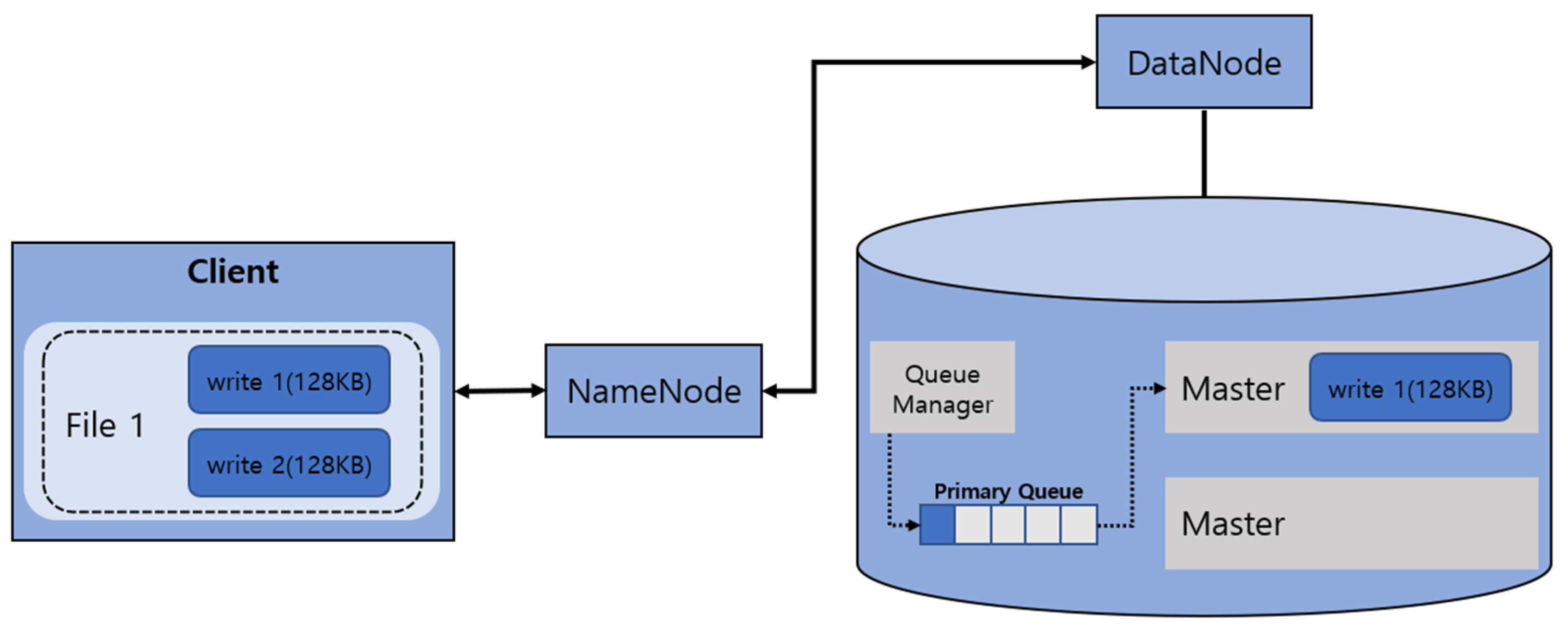
Figure 1 shows the basic I/O process of the EC-based HDFS. It refers to I/O processing of files through the DataNode after fetching the file layout through the NameNode from a client. The file layout means the file configuration information about data that are stored by clients. The DataNode consists of a queue manager to assign events and masters and workers to perform services, respectively.
When an I/O request of data storage from a client in the EC-based HDFS is sent to the NameNode, the queue manager in the NameNode puts the event generated when the client request occurs into the primary queue. Multiple workers in the DataNode fetch events from the primary queue and call appropriate service functions from the master or slave to process and return the results. Although two requests (write 1, write 2) are generated, only one is processed because a single write request is taken and processed by a single worker for concurrency control.
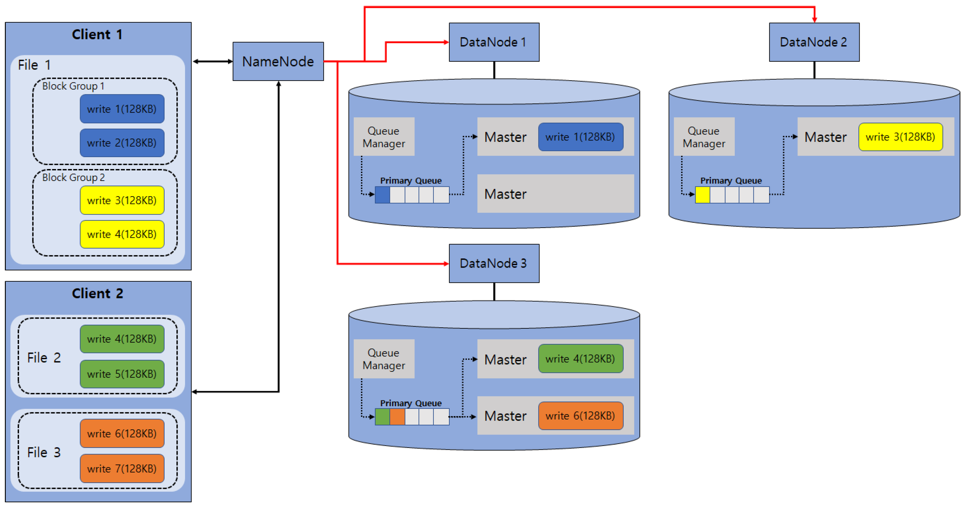
Figure 2 shows how to process multiple file I/Os through multiple clients and DataNodes. It shows the I/O processes of three files concurrently, in which client 1 performs the I/O processes of one file consisting of two block groups, and client 2 performs the I/O processes of two files. As expressed in Figure 1, different block groups can be processed concurrently. However, as mentioned in Figure 2, since requests of the same block group are taken and processed by a single worker for concurrency control, only a total of four workers are running, and the others are accumulated in the primary queue. Thus, when I/O requests for small-sized files are too many, those requests are accumulated in the primary queue, thereby creating a problem of too many waiting I/O requests.
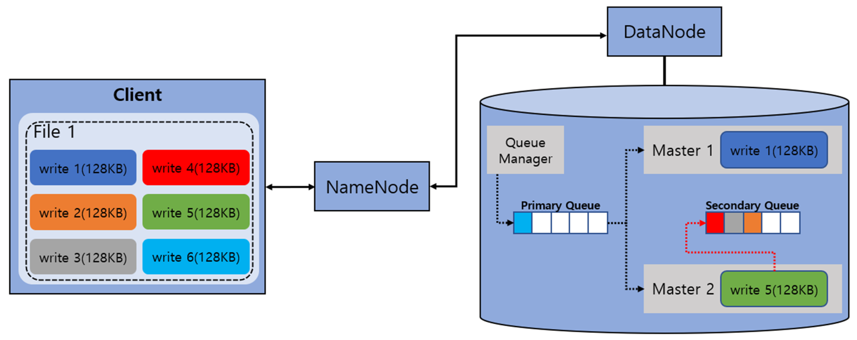
Following the explanations in Figure 2, Figure 3 describes a method of distributing and storing cells, which are generated by encoding write 1 by the master inputted through the queue manager in DataNode 1.
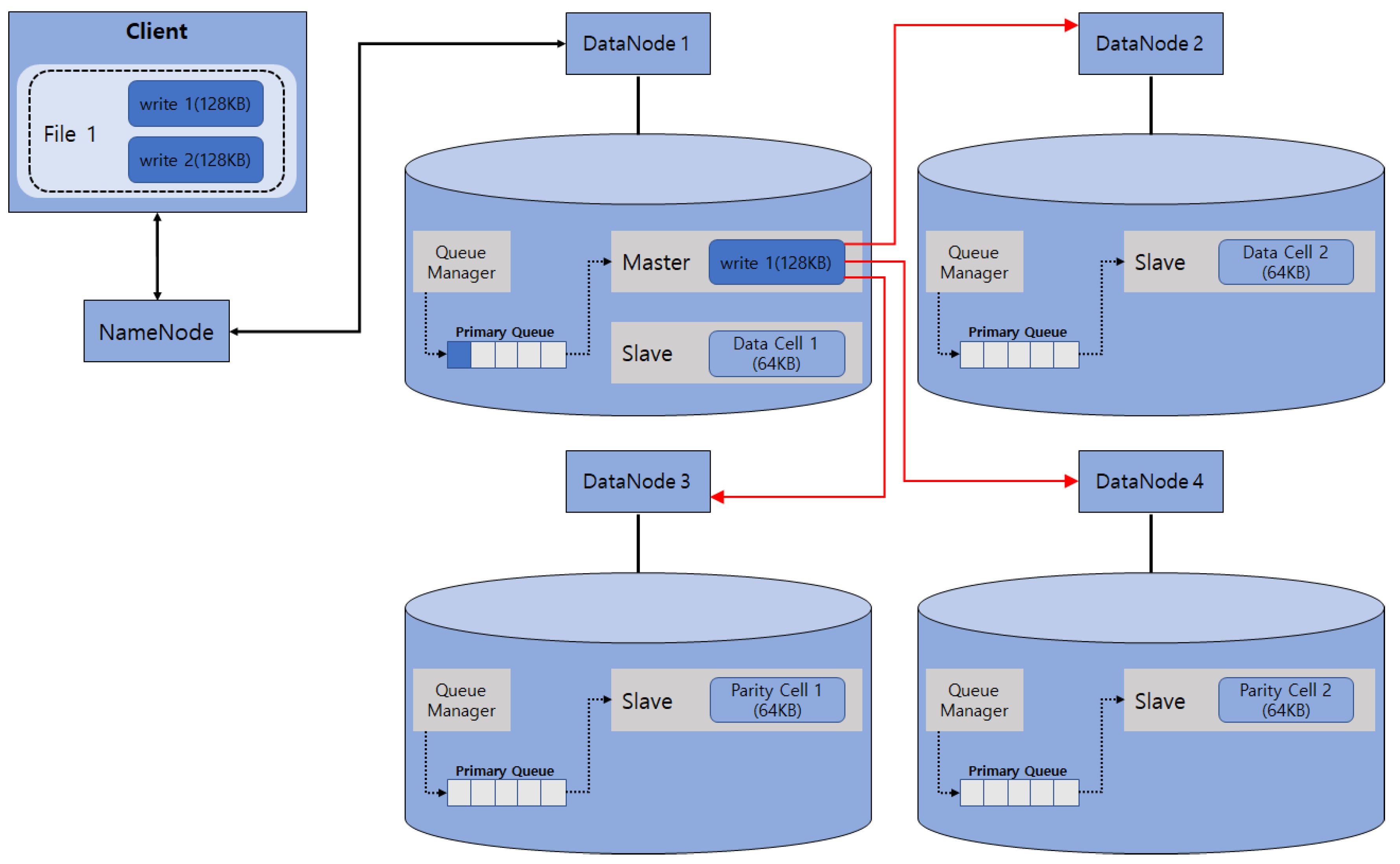
Figure 3 shows a process after the write 1 write request on file 1 from the client in the 2 + 2 structured EC-based HDFS. After generating two data cells and two parity cells from the original data through the encoding process by the master in DataNode 1, those cells are distributed to the slaves through the queue manager of each DataNode and stored in the disks. That is, the master contains the encoding-related and data distribution-related overheads, resulting in its processing time taking too long. In particular, even if there are multiple workers available, multiple requests for the same block group should be processed one at a time sequentially, and the I/O processing time of a single I/O takes a long time due to encoding-related or cell distribution-related overheads, thereby incurring the rapid degradation of I/O performance overall.
Furthermore, when I/O requests are distributed to multiple DataNodes through encoding, they are converted into multiple small-sized I/O requests, including parity blocks, in which performance degradation is worsened because it produces many smaller-sized I/O requests as blocks are divided further.
Table 1 presents the I/O size and the number of I/Os between DataNodes according to EC setting. The 2 + 2 EC setting means that the number of DataNodes that store data cells is two, and the number of DataNodes that store parity cells is two; for 128 KB data, the I/O size of each cell is 64 KB through encoding, and the number of I/Os is four. The 4 + 2 EC setting means that the number of DataNodes that store data cells is four, and the number of DataNodes that store parity cells is two, and for 128 KB data, the I/O size of each cell is 32 KB through encoding, and the number of I/Os is six. Similarly, the 8 + 2 EC setting is expressed as 10 16 KB I/Os. Finally, the 16 + 2 EC setting is expressed to 18 8 KB I/Os, in which overall system performance degradation occurs due to waiting I/Os in the primary queue, which are not processed, as a result of very-tiny-sized I/O requests.
Next, the recovery problems occurring in the EC-based HDFS are discussed in detail. The data and parity cells generated in the EC-based HDFS are distributed and stored in different disks, which is similar to the replication case, to ensure availability. As described above, if a single cell is stored in multiple disks, it is classified into clustering storage and nonclustering storage modes according to cell distribution and storage method.
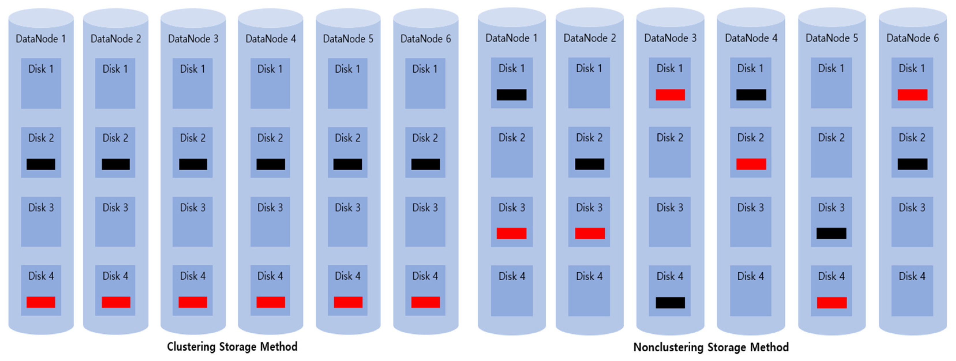
The clustering storage mode means that required disks are clustered in advance and cells are distributed and stored only within the cluster when storing cells, which is used in GlusterFS, Ceph, and so forth among various EC-based distributed file systems. The nonclustering storage mode means that all disks are recognized as one cluster, and files are distributed and stored in arbitrary disks; this is typically used in EC-based HDFS. Figure 4 shows examples of clustering and nonclustering storage modes, which display the 4 + 2 EC storage with six DataNodes, each containing four disks.
The clustering storage mode in Figure 4 selects one disk only from each of six DataNodes, thereby designating a total of four clusters and distributing and storing cells within the designated groups, whereas the nonclustering storage mode stores cells in arbitrary disks from among all disks.
The clustering storage mode easily manages resources and stores files because cell allocation is performed at the cluster level. However, it has a drawback of limiting the recovery performance because recovery is performed only at the cluster level. The nonclustering storage mode struggles to manage resources because cells are allocated randomly throughout all disks, but its recovery performance is not limited, because recovery is performed throughout all disks.
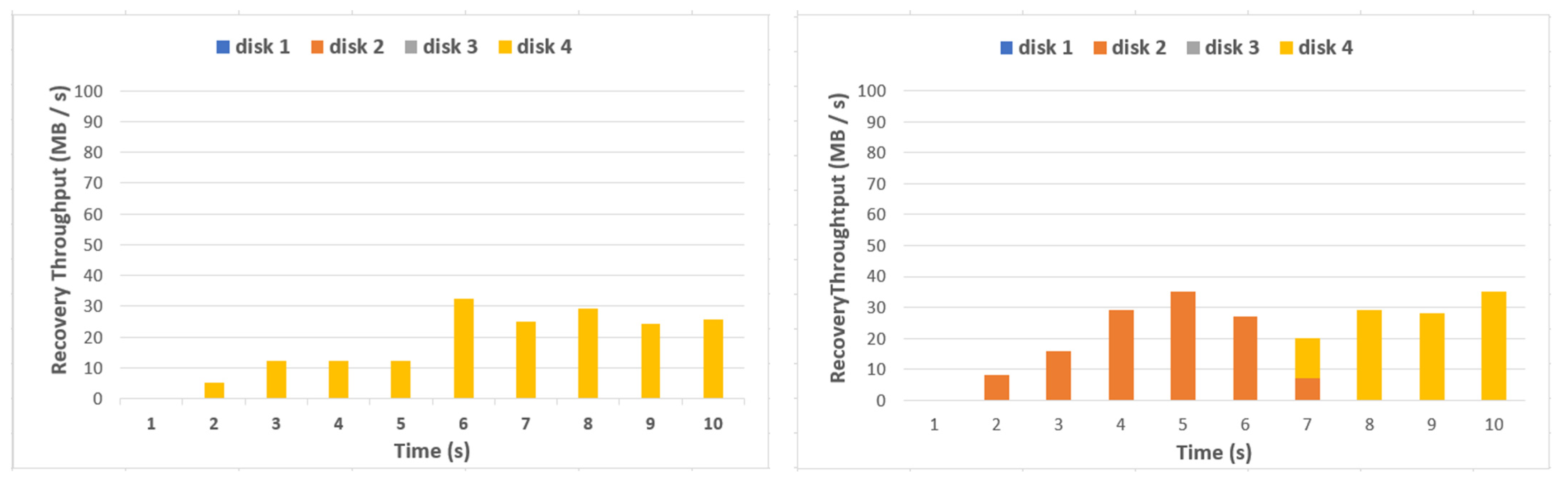
Figure 5 shows the disk usage in DataNode 1 during single-thread fault recovery when a fault occurs in disk 4 of DataNode 6 in Figure 4.
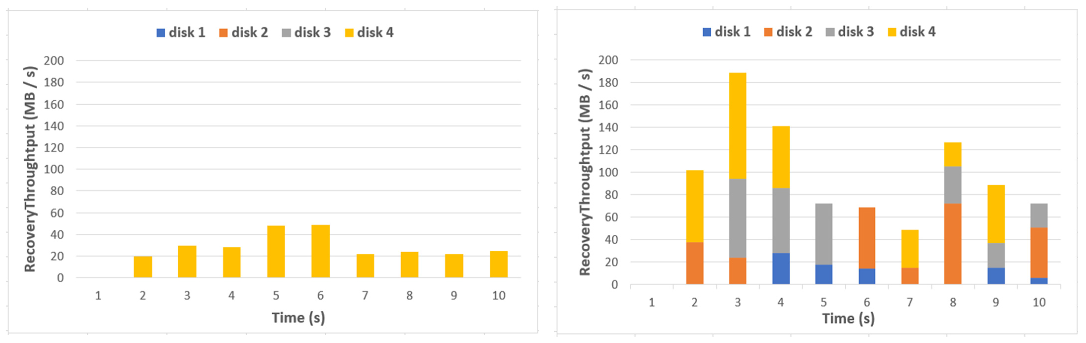
As shown in Figure 5, I/Os occur only in disk 4, which is the same cluster as that of the fault disk during recovery time in the clustering storage mode, whereas I/Os occur in disks 2 and 4 sequentially according to the fault file. Since a single thread performs recovery, recovery performance is similar, but there is a difference in disks utilized during recovery. Figure 6 shows the disk usage in DataNode 1 during multithread fault recovery when a fault occurs in disk 4 of DataNode 6.
As shown in Figure 6, since I/O occurs only in disk 4, which is the same cluster as that of the fault disk during recovery in the clustering storage mode, performance improvement was minimal despite of the use of multithreads. The recovery performance increases as the recovery is performed in multithreads in the nonclustering storage mode, and many disks are utilized in the recovery. However, the mean recovery performance is 94 MB/s in the nonclustering storage mode, which is very low compared with the overall system performance. In Section 4, the efficient data distribution and storage method and parallel recovery technique in the EC-based HDFS are presented.
4. Efficient Data Distribution and Storage Method
In this section, I/O buffering and I/O combining methods are described to improve I/O performance of EC in the EC-based HDFS.
4.1. I/O Buffering
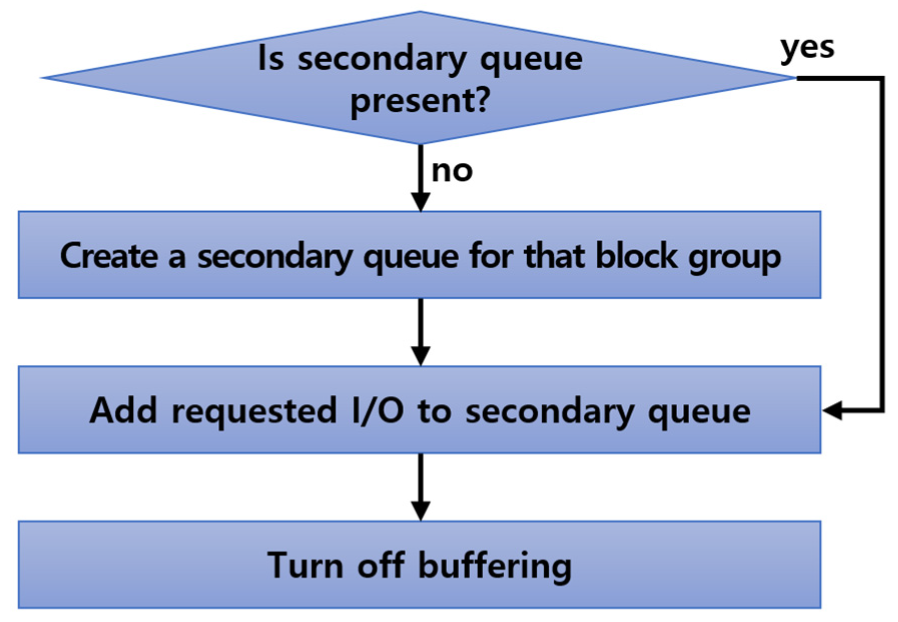
In the I/O buffering step, the secondary queue is created for the block group that is processing I/Os, thereby collating I/Os in the queue rather than the standby of I/O request for the same basic block group. Figure 7 shows the processing procedure of the I/O buffering step.
In the I/O buffering process, it is first checked whether the secondary queue is present. If it is not present, the secondary queue is created, and the I/Os in the queue are added to the secondary queue. If it is present, the requested I/Os are added to the already created secondary queue. Once added, the secondary queue setting is finally turned off. Since standby I/Os in the primary queue can be minimized through I/O buffering, it can prevent the performance degradation of the system. Figure 8 shows the processing method of the I/O buffering step.
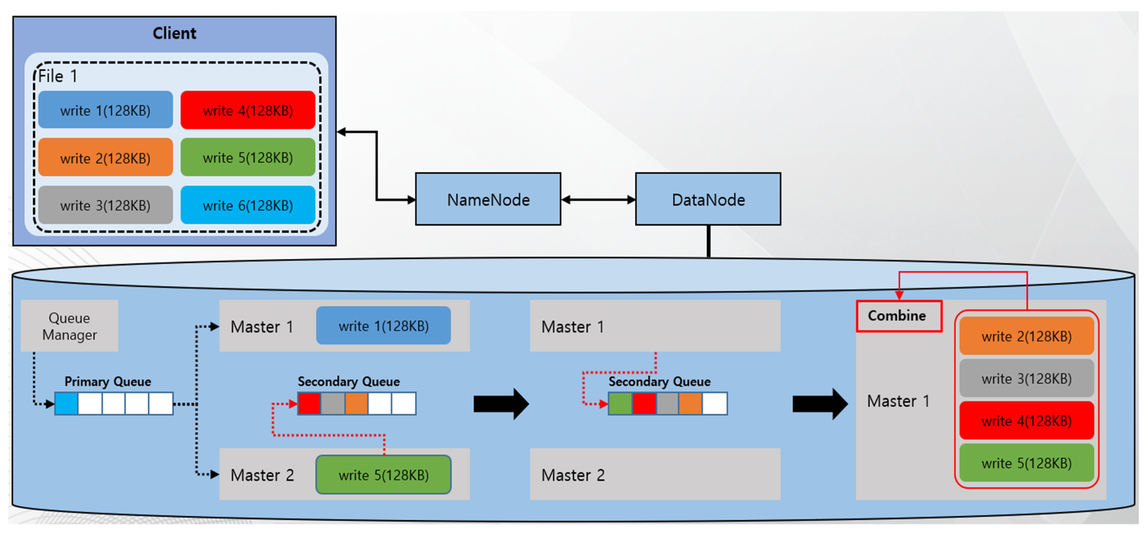
The I/O requests for the same file are not standby, while the first I/O of the file is performed in the I/O buffering step, in which other workers can process those requests. That is, while master 1 performs registration to conduct write 1 in file 1, master 2 fetches write 2 in file 1 and processes it. Here, master 2 also registers that it is performing I/O buffering of the file.
Since master 2 verified that master 1 was processing write 1 in file 1 through the file information in process, the secondary queue in relation to the file is created, and write 2 is registered in the secondary queue. Next, the above process is iterated, showing that master 2 fetches write 5. Thus, Figure 8 shows the accumulation of write 2, write 3, and write 4 on file 1 in the secondary queue.
4.2. I/O Combining
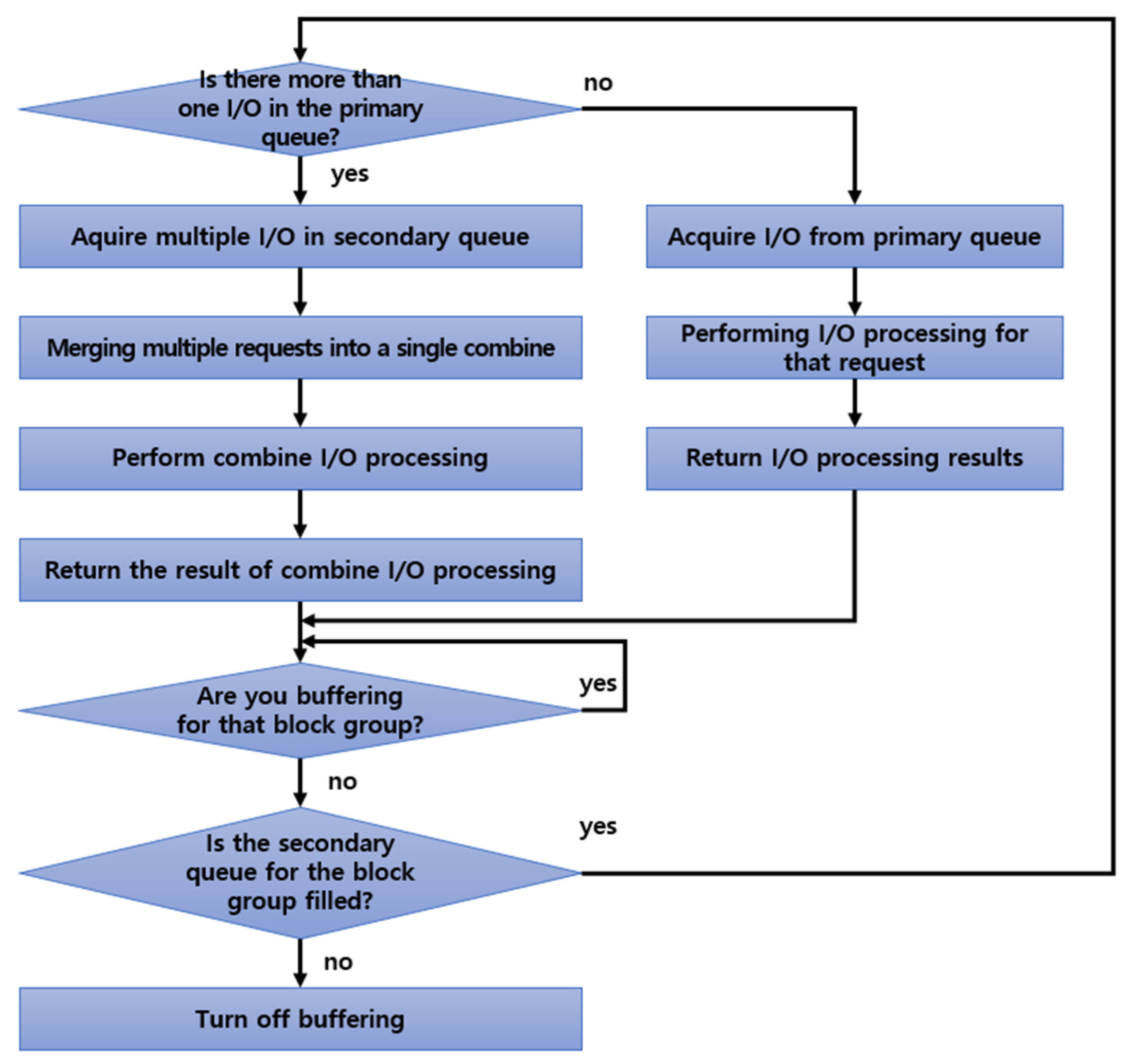
The I/O combining step refers to combining I/Os accumulated in the secondary queue through the I/O buffering step and processing them as a single I/O rather than processing them one at a time as single I/Os by workers. Figure 9 shows the processing procedure of the I/O combining step.
First, whether more than two I/Os are present in the primary queue is checked. If only one I/O is present, standby I/Os in the primary queue are acquired to perform I/O processes and return the process results. After returning the result, it moves to a step to check whether queuing of the data occurs.
If more than two I/Os are present in the primary queue, multiple I/Os are acquired from the secondary queue and combined into one using the combining technique. In addition, the combined I/Os are created and combined I/Os are processed, thereby returning the process results. Here, because it is not multiple single I/Os, it can be extended that multiple combined I/Os are returned individually, or combined I/Os are processed in the clients. By verifying whether buffering is progressing for the next block group, standby is performed until the buffering process is terminated. If it is not buffering, whether the secondary queue is filled or not is verified. If it is filled, I/O combining is reperformed. If the secondary queue is empty, the setting that the corresponding block group is processing I/Os is turned off and the processing is terminated.
Figure 10 shows the completed processing of write 1, which is owned by master 1, while master 2 is processing write 5.
After master 1 returns the processing results of write 1, it verifies whether buffering of the group is progressing and stands by until the buffering is complete. The next step is that master 1 checks the secondary queue after master 2 completes buffering. If multiple I/Os are accumulated in the secondary queue, they are combined into the designated unit to be processed as a single I/O. The final step is to fetch four I/Os from the secondary queue and integrate them into a single combined I/O to process. Multiple I/Os can be processed as one through I/O combining, which increases I/O size, and the number of I/Os decreases, resulting in significant improvements in I/O efficiency due to the mitigation of network loads and contention overall.
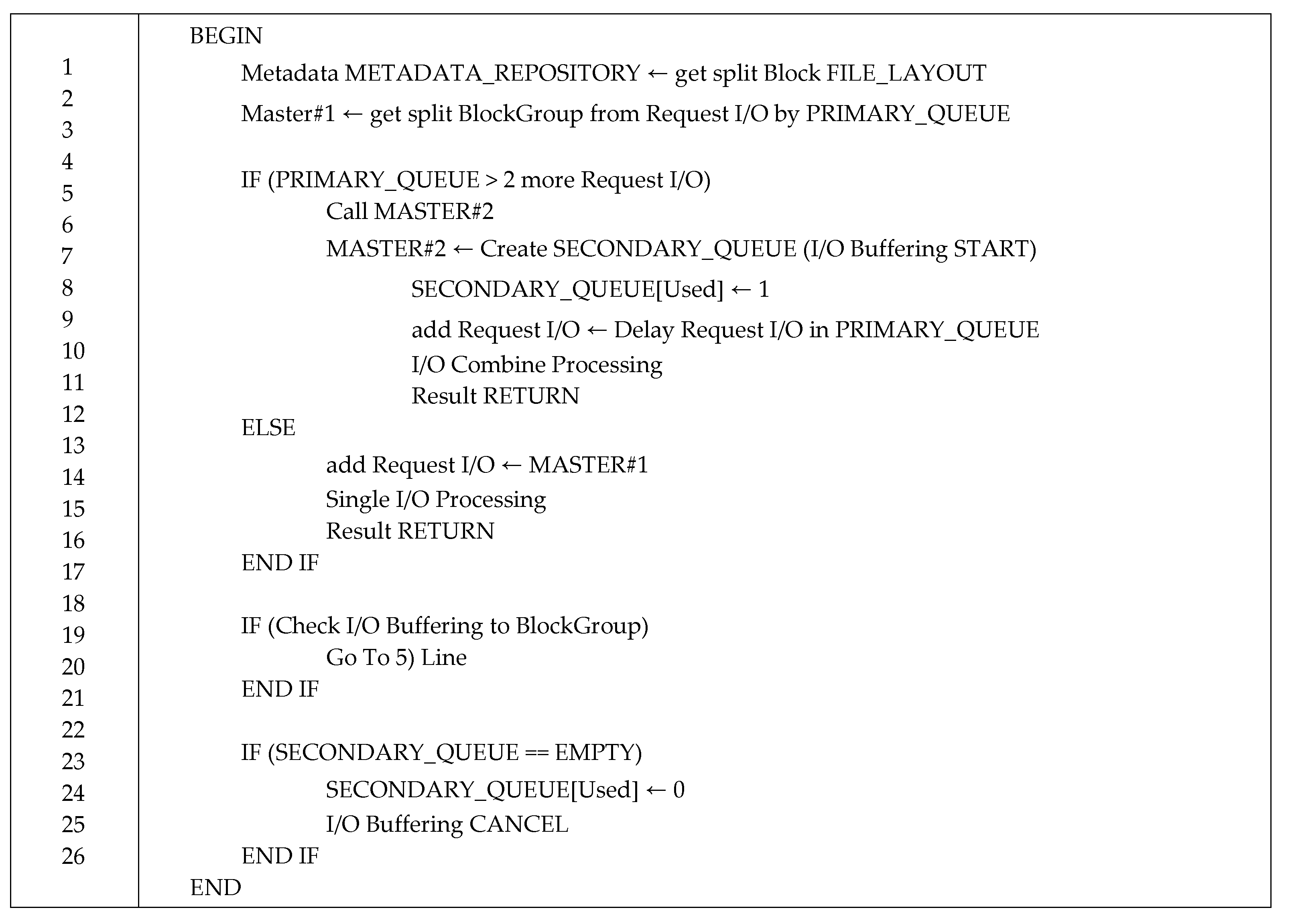
Figure 11 shows the algorithms applied with I/O buffering and I/O coupling.
(2–3) When a client saves a file to store, divide the file into blocks of a certain size and record the metadata in each block through the file layout process. After recording, divide it into block groups and pass it on to the master of the DataNode.
(5–11) The master checks the primary queue for more than one requested input/output through the queue manager. If you have more than one master, call another master within the DataNode and record (“1”) that secondary queues are in use while generating secondary queues. In addition, the called master performs the I/O buffering process, which adds a queued input/output to the primary queue. When the addition is completed, I/O combining is used to convert to one input/output and return the result.
(12–16) If there are fewer than two requested inputs/outputs (one input/output) when checking the primary queue, do not invoke the other master, but take the input/output and process it and return the result.
(18–25) After the I/O combining process, go to 5 if I/O buffering is in progress for the block group. If there is no I/O in the secondary queue, record (“0”) that the secondary queue is not in use, and I/O buffering is terminated.
Table 2 presents the internal I/O processing size according to the combined number of I/Os to be processed through I/O combining of 16 128 KB-sized requests in 16 + 2 EC.
As presented in Table 2, when 16 128 KB-sized I/Os are processed one at a time in 16 + 2 EC, a total of 288 8 KB-sized I/Os are needed to be processed, whereas only 18 128 KB-sized I/Os are needed to be processed if 288 I/Os can be combined into multiple sets, each consisting of 16 I/Os.
5. Efficient Data Recovery Method
In this section, a parallel recovery technique is introduced that can be used in the EC-based HDFS to improve recovery performance by overcoming the recovery problem occurring in the EC-based HDFS (described in Section 2).
5.1. Distribution of Disk I/O Loads
Because a single file in the EC-based HDFS is divided into multiple data and parity cells and stored, it is expected to have a distribution of disk I/O loads during parallel recovery. In addition, contention is more likely to occur in the limited disks as more multiple recovery workers are operated to increase the small-scale distributed file system or parallel recovery performance, which requires high space efficiency, although the numbers of DataNodes or disks are small. In particular, when block-level processing is required, such as in fault recovery time, disk I/O loads would be worse. In this section, a method for improving the parallel recovery performance is explained by avoiding I/O loads in disks, which are limited resources at the time of parallel recovery.
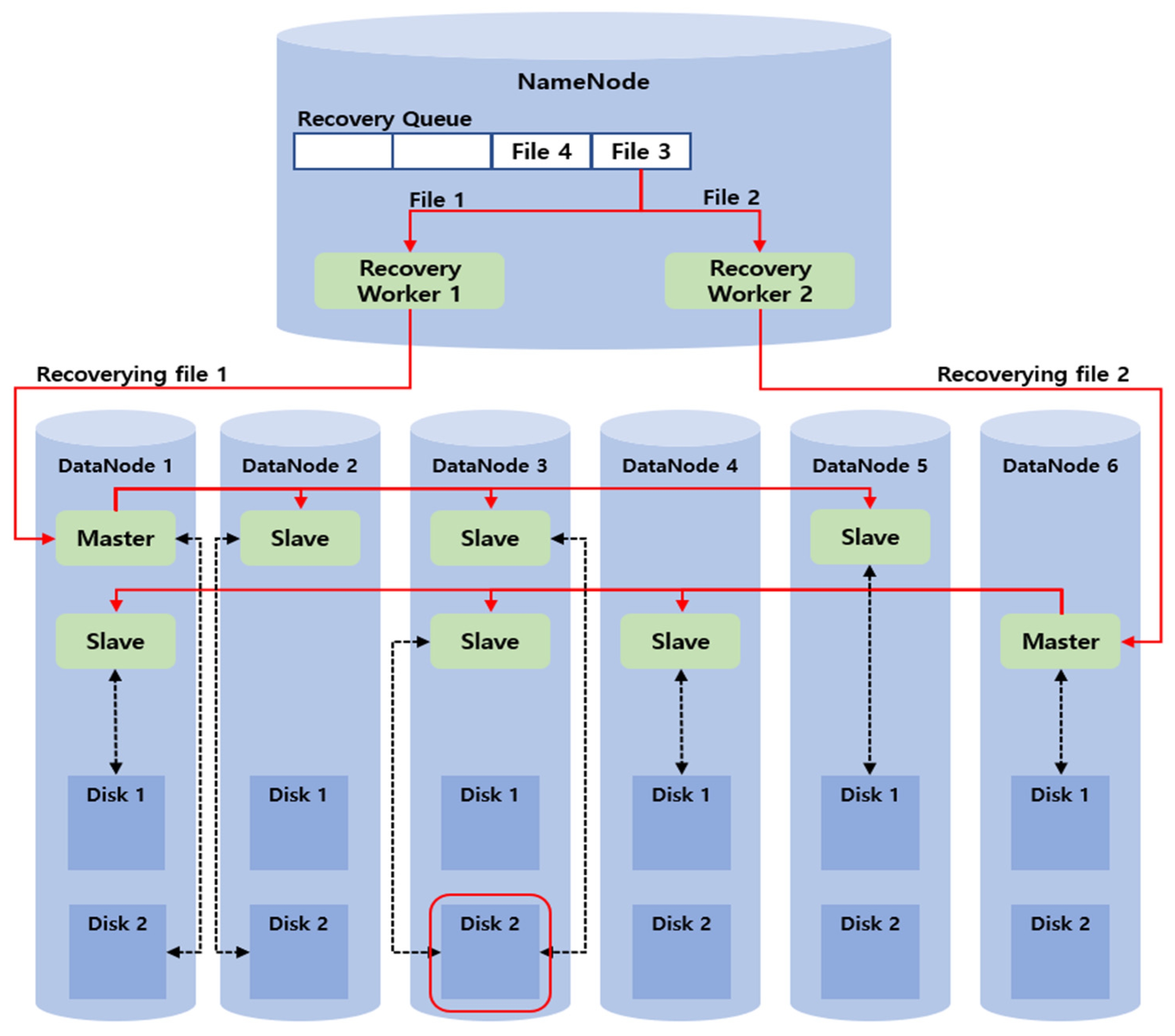
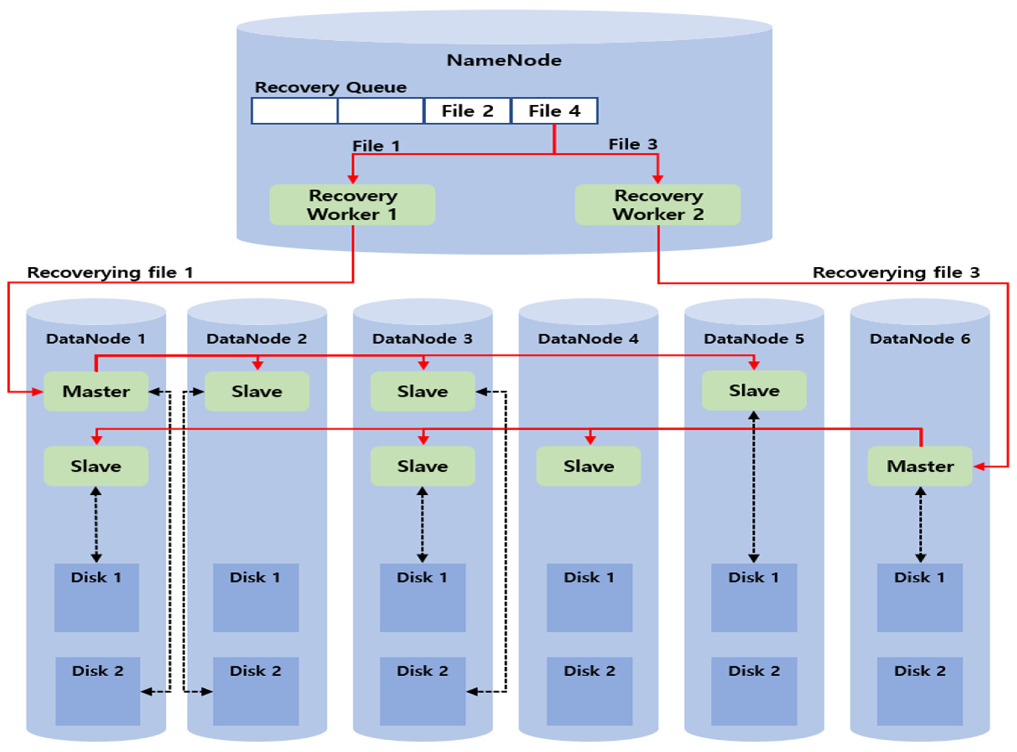
Figure 12 shows an example of a disk load when parallel recovery is performed. The file information to be recovered in the recovery queue is sequentially accumulated in the NameNode, in which file 1 is recovering in the current recovery worker 1 and file 2 is recovering in the recovery worker 2 in parallel. File 3 and file 4, which are recovered next, are present in the recovery queue, and the recovery worker that completed the recovery fetches the next file information in the recovery queue and performs the recovery.
Once recovery worker 1 fetches the recovery information about file 1 and requests the recovery from DataNode 1, which is the master of file 1, one of the workers in DataNode 1 is designated as the master and starts the recovery. In addition, once recovery worker 2 fetches the recovery information about file 2 and requests the recovery from DataNode 6, which is the master of file 2, one of the workers in DataNode 6 is designated as the master and starts the recovery. Thus, disk loads occur due to the concurrent access to disk 2 of DataNode 3.
The disk I/O load distribution technique proposed in this study is a method in which the load information table is placed to check the access loads of the disks in the NameNode, and recovery is performed only when the disk to be accessed in response to the recovery request can bear the load. To distribute the disk I/O loads in this study, only one I/O was set to be allowed in a single disk at the time of fault recovery.
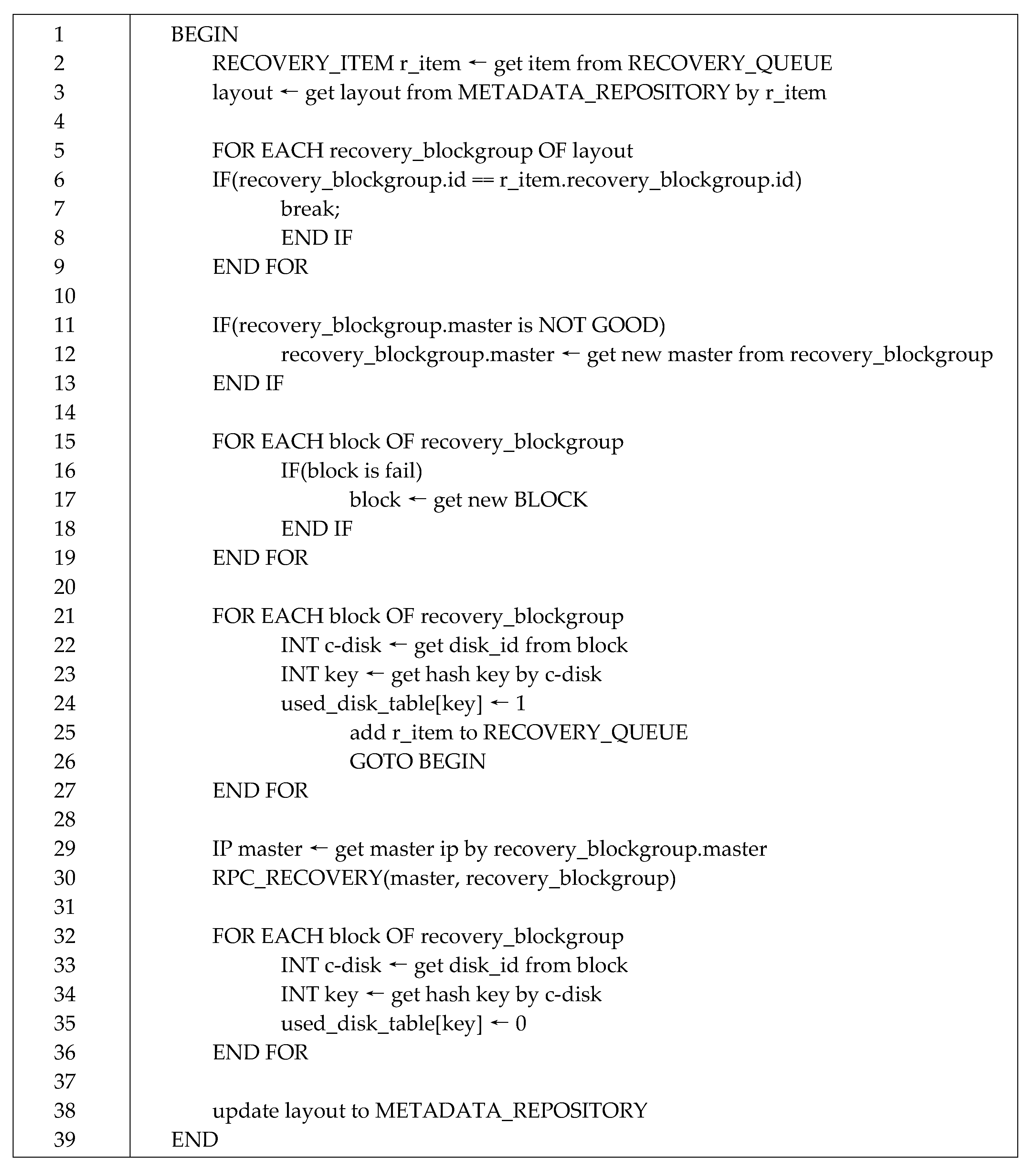
Thus, whether or not the recovery was pursued was determined after checking the availability of the disk to be accessed before the recovery request from the recovery worker, and the disk accessed in response to the recovery request is marked as “in use” and then as “completed” when the recovery is complete. This marking method was applied to the EC-based HDFS. In addition, a method to check the disk availability prior to recovery initiation was applied. Figure 13 shows the core part in the algorithm where the disk I/O load distribution technique is applied.
(2–9) The EC-based HDFS fetches the file information to be recovered from the recovery queue, as well as the layout of the file through the metadata repository, thereby checking whether the ID of the block group to be recovered is the same.
(11–19) After checking the block group ID, the status of the master that will start the recovery of the block group is checked. If the status is not normal, a new block within the block group is designated as the master, or a new block is assigned to replace the fault block.
(21–27) The related disk availability for each block to be recovered is checked. If the disk is “in-use (1),” the recovery information in process is put into the recovery queue, and the process is performed again from the beginning.
(29–36) The recovery starts when the recovery request is entered from the master. Once the recovery is complete, the in-use disk is marked as “not using (0).”
(38) Finally, the layout of the modified file is stored in the metadata repository and renewed with the new information.
Figure 14 shows the parallel recovery method by two recovery workers according to the disk I/O load distribution technique in the same environment as that in Figure 12 after applying the disk I/O load distribution algorithm.
Recovery worker 1 and recovery worker 2 fetch the recovery information of file 1 and file 2, respectively, sequentially. After recovery worker 1 checks the availability of the disk needed for the recovery of file 1 first, the disk is set to “in-use,” and the recovery request is sent to the master. Next, recovery worker 2 checks the availability of the disk needed to recover file 2. Here, if recovery worker 2 checks that the disk 2 of DataNode 3 is “in-use,” it reinserts file 2 into the recovery queue and fetches the next standby file 3. After recovery worker 2 checks the availability of the disk needed for the recovery of file 3, the disk is set to “in-use,” and the recovery request is sent to the master.
5.2. Random Block Placement
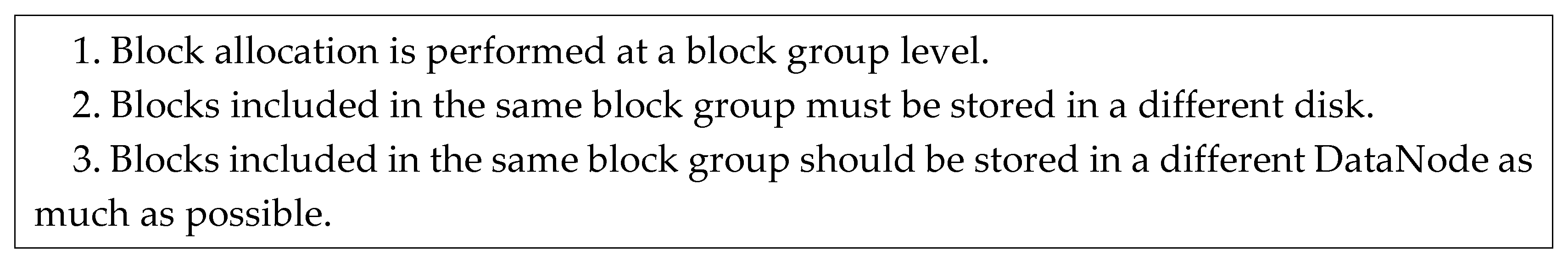
Block placement refers to the designation of specific disks from available disks and the creation of new blocks. The data and parity cell allocation is performed according to the designated rule to improve data availability and I/O performance based on the volume setup in the EC-based HDFS. Figure 15 describes the rules for creating new blocks.
In the clustering storage mode, a disk that belongs to the designated cluster is the target of block placement. On the other hand, all disks are the targets of block placement in the nonclustering storage mode. The sequential block placement method proposed in this section is a method for placing a block in the DataNode and disk according to a determined order, and the random block placement is a method for randomly placing a block in the DataNode and disk.
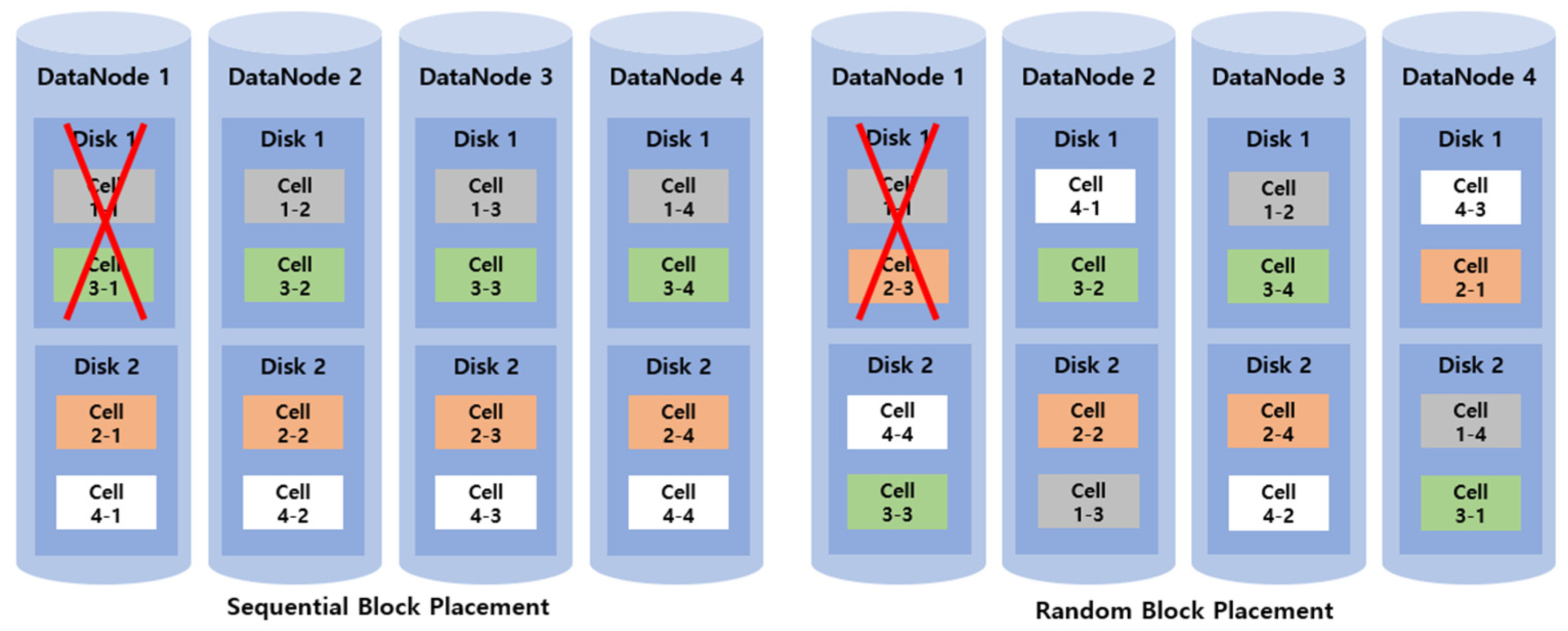
Figure 16 shows examples of sequential and random block placement techniques used in the 2 + 2 EC-based HDFS, consisting of four DataNodes each with two disks. Four cells are stored in the 2 + 2 EC volume.
According to the basic rule of the block placement, four cells are stored in a different DataNode and disk. Blocks are placed sequentially in the order (DataNode 1, Disk 1) → (DataNode 2, Disk 1) → (DataNode 3, Disk 1) → (DataNode 4, Disk 1) in the sequential block placement technique, and blocks are randomly placed in the DataNodes and disks in the random block placement technique.
Since the sequential block placement technique places blocks according to the determined order, block placement is convenient and blocks are likely to be placed uniformly. However, the random block placement technique requires checking whether blocks are placed in different DataNodes, and disks and blocks are likely to be placed more in specific DataNodes and disks. Thus, the sequential block allocation technique may be advantageous in a general I/O condition, because its block displacement is simple and loads distributed as blocks are distributed evenly. However, since blocks are placed according to the determined order in the sequential block placement, the probability of using blocks stored in the disks is very low at the time of fault recovery.
If a fault occurs in disk 1 of DataNode 1, the number of blocks accessible to recover the fault will differ with the block placement method. In the sequential block placement technique, only three disk stripes, (DataNode 2, Disk 1), (DataNode 3, Disk 1), and (DataNode 4, Disk 1), are utilized to recover cells 1-1 and 3-1 at the time of file recovery. In contrast, in the random block placement technique, five disks can be utilized, (DataNode 3, Disk 1/Disk 2), (DataNode 4, Disk 1/Disk 2), and (DataNode 2, Disk 2), at the time of file recovery. Thus, since the resources that can be utilized at the time of fault recovery are limited depending on the block placement technique used, it is important to utilize the random block placement technique in which as many resources can participate in the recovery as possible for efficient parallel recovery in EC.
5.3. Matrix Recycle
The decoding task that recovers lost data in EC is performed in the following order: data acquisition → decoding matrix creation → decoding process. Data acquisition refers to a step to read available data required for decoding. Decoding matrix creation refers to a step to create a decoding matrix required for decoding according to the EC setup and fault location. Finally, decoding refers to a step to perform decoding using the acquired data and decoding matrix.
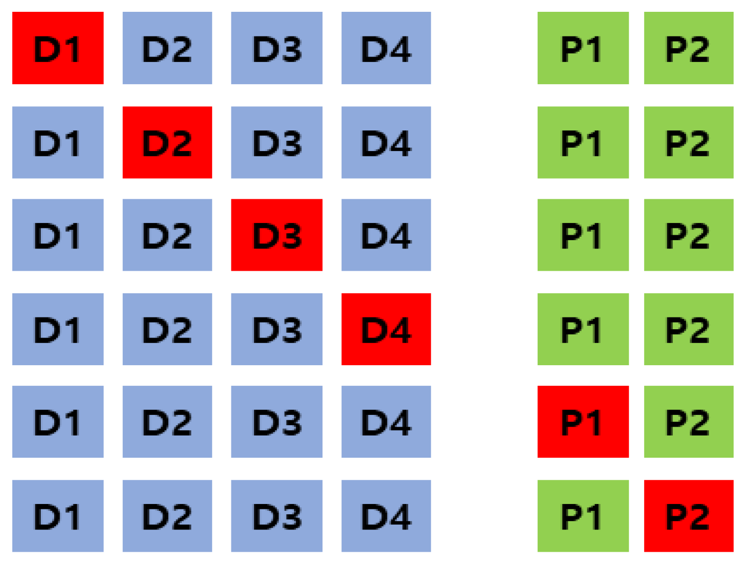
In particular, the required number of matrices for decoding differs according to EC attributes, such as EC, number of data divisions, number of created parities, and fault location and number. For example, if a single disk fault occurs in EC with four data cells and two parity cells in the EC-based HDFS using a single volume, the required number of matrices for decoding is six.
In Figure 17, cells D1 to D4 are data cells and P1 and P2 are parity cells. The red color indicates the fault location, and a total of six decoding matrices are required according to the fault location in a single fault. Table 3 presents the number of matrices occurring during multiple faults according to the K + M value.
As presented in Table 3, as the K + M value increases, the number of used matrices increases. In particular, as the number of data divisions increases, the number of matrices increases exponentially. Thus, as the used EC volumes are various and the number of fault tolerances increases, the required number of decoding matrices increases.
However, with the same fault attributes, the used matrices are the same. For example, for the same EC and the same fault index in multiple volumes with a 4 + 2 attribute, the used matrices are the same. That is, if the number of data divisions, the number of parities, erasure code, and stripe size are the same, even if the volume is different in the EC structure, then the used matrices are the same for the fault in the same location. Thus, this study minimizes the time to create matrices for decoding by recycling the matrices if the same fault attributes are found after registering the created matrices in the pool.
Figure 18 shows the overall data structure used to recycle matrices.
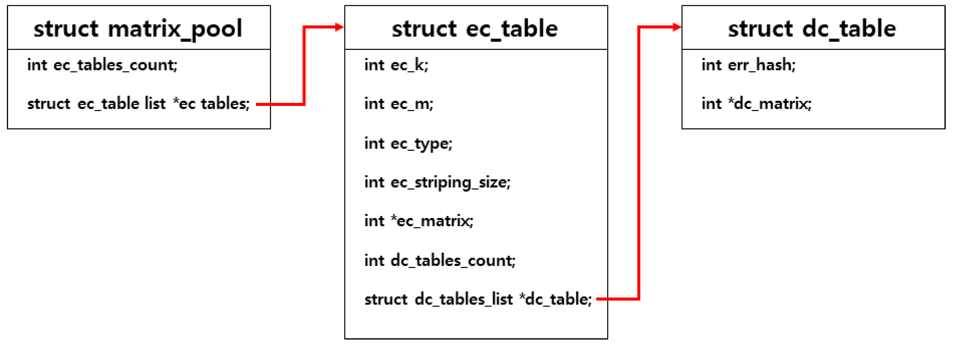
Figure 19 shows the data structure comprising the matrix. struct matrix_pool, which represents the overall structure, has struct ec_table consisting of encoding information and matrix. struct ec_table contains struct dc_table consisting of decoding information and matrix, which are related to the corresponding encoding information.
struct matrix_pool consists of ec_tables_count, which represents the number of ec_table, and ec_tables, which represent the list of ec_tables.
In struct ec_table, the number of data divisions (ec_k), the number of parities (ec_m), the EC type to be used (ec_type), the striping size (ec_striping_size), and the encode matrix (ec_matrix) are required information for encoding, and the number of dc_tables (dc_tables_count) and the list of dc_tables (dc_tables) are decoding-related information.
struct dc_table stores information and matrix required for decoding, which consists of information to check the fault location (err_hash) and related decoding matrix (dc_matrix). err_hash value in dc_table is a hash value calculated based on the fault count and location, which is used to identify whether the fault occurs in the same location.
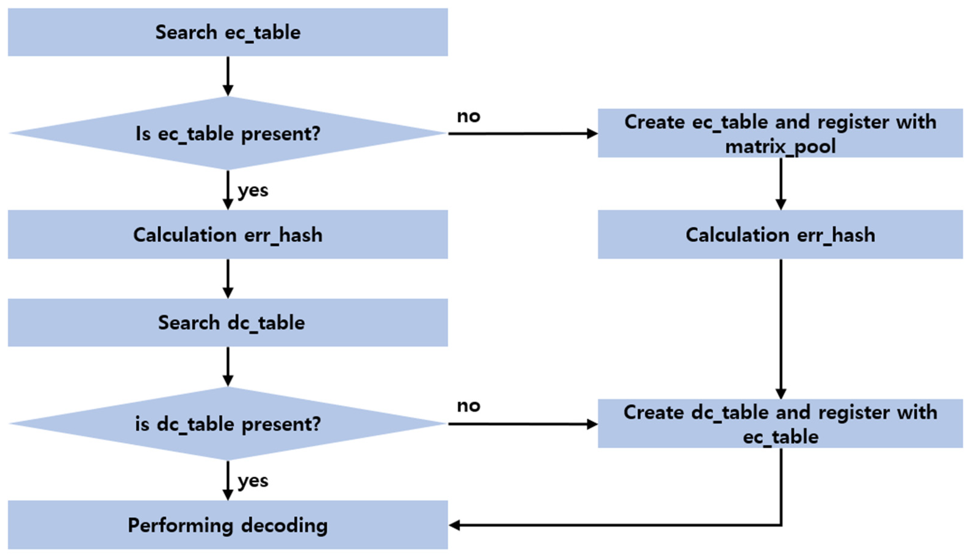
Figure 19 shows the matrix recycle step. When decoding is requested, ec_table, whose ec_k, ec_m, ec_type, and ec_stripe_size are the same in matrix_pool, is searched. If ec_table is found, err_hash is calculated based on fault information, and dc_table whose err_hash is the same in ds_table_list registered in ec_table is searched. If dc_table is found, decoding is performed using dc_matrix.
If ec_table is not found, ec_table is created and registered in matrix_pool. Next, err_hash is calculated based on the next fault information, and dc_table is created and registered in ec_table followed by performing decoding.
If ec_table is found but the related dc_table is not found, dc_matrix is created based on encoding information and ec_matrix and registered in ec_table followed by performing decoding using dc_matrix.
6. Performance Evaluation
In this section, the superiority of the storage and recovery techniques proposed for EC-based HDFS in this study is verified through performance evaluation.
The EC volume used in performance evaluation consists of one NameNode and six DataNodes with 4 + 2 EC. The EC-based HDFS was installed as follows: in each node, Intel CPU i7-7700 3.60 Mhz, 16 G memory, one 7200 rpm HDD, and 1 G Ethernet were mounted, running over the Ubuntu 16.04.01 operating system. The proposed methods in this study were applied, and performance comparison was conducted.
6.1. Performance of Data Distribution Storage
The data distribution storage performance compared the basic EC-based HDFS with the I/O buffering technique and I/O combining technique-applied EC HDFS-BC proposed in this study.
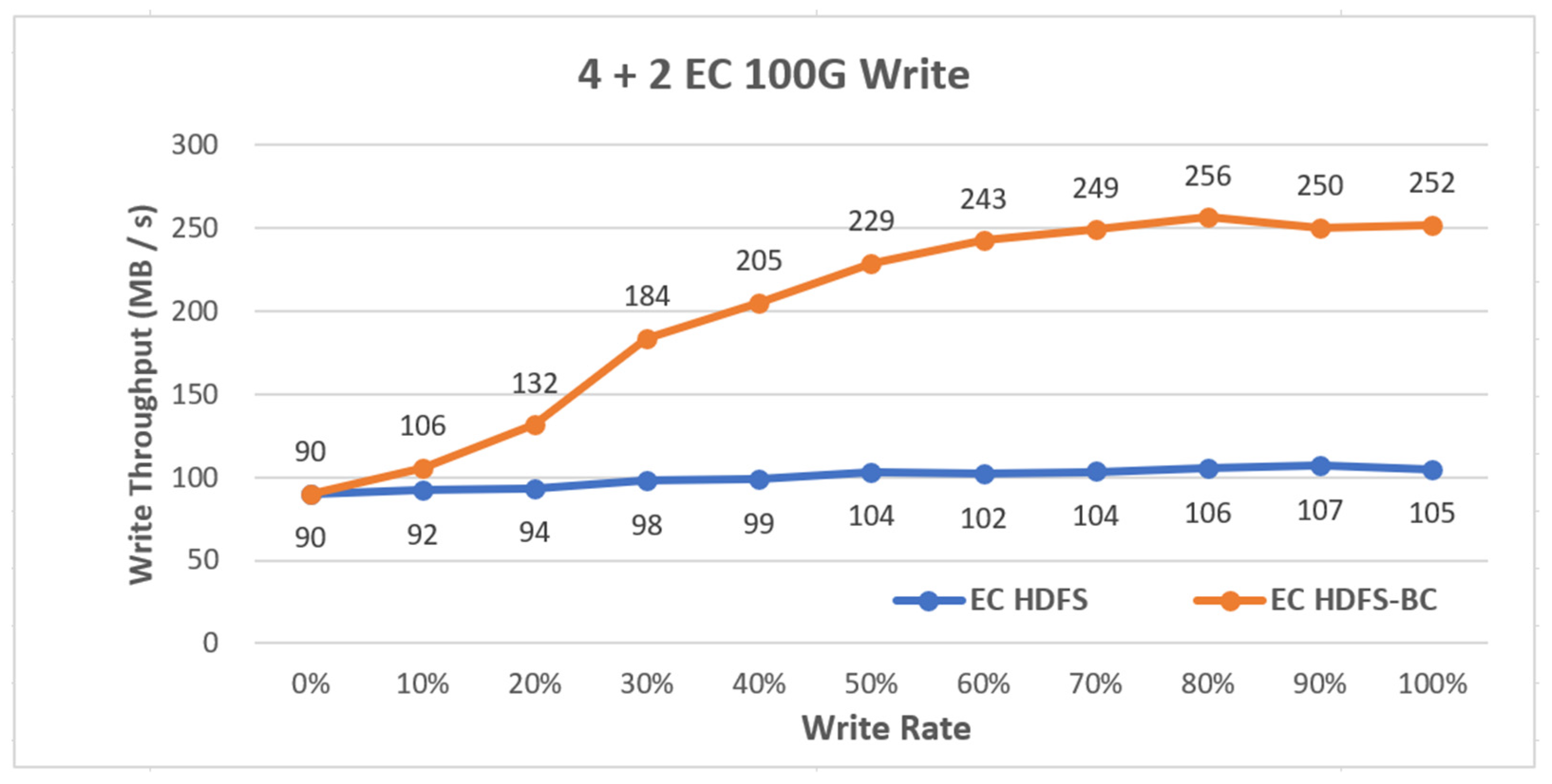
Figure 20 shows the disk throughput when storing 100 GB sample data to each distribution file system after creating the sample data in the EC-based HDFS and EC HDFS-BC systems. The EC-based HDFS showed a slight performance increase though, but no significant change was shown throughout the experiment, whereas the EC HDFS-BC system exhibited a high write throughput as it closed to the file storage completion, which was improved about 2.5-fold compared with that of the EC-based HDFS.
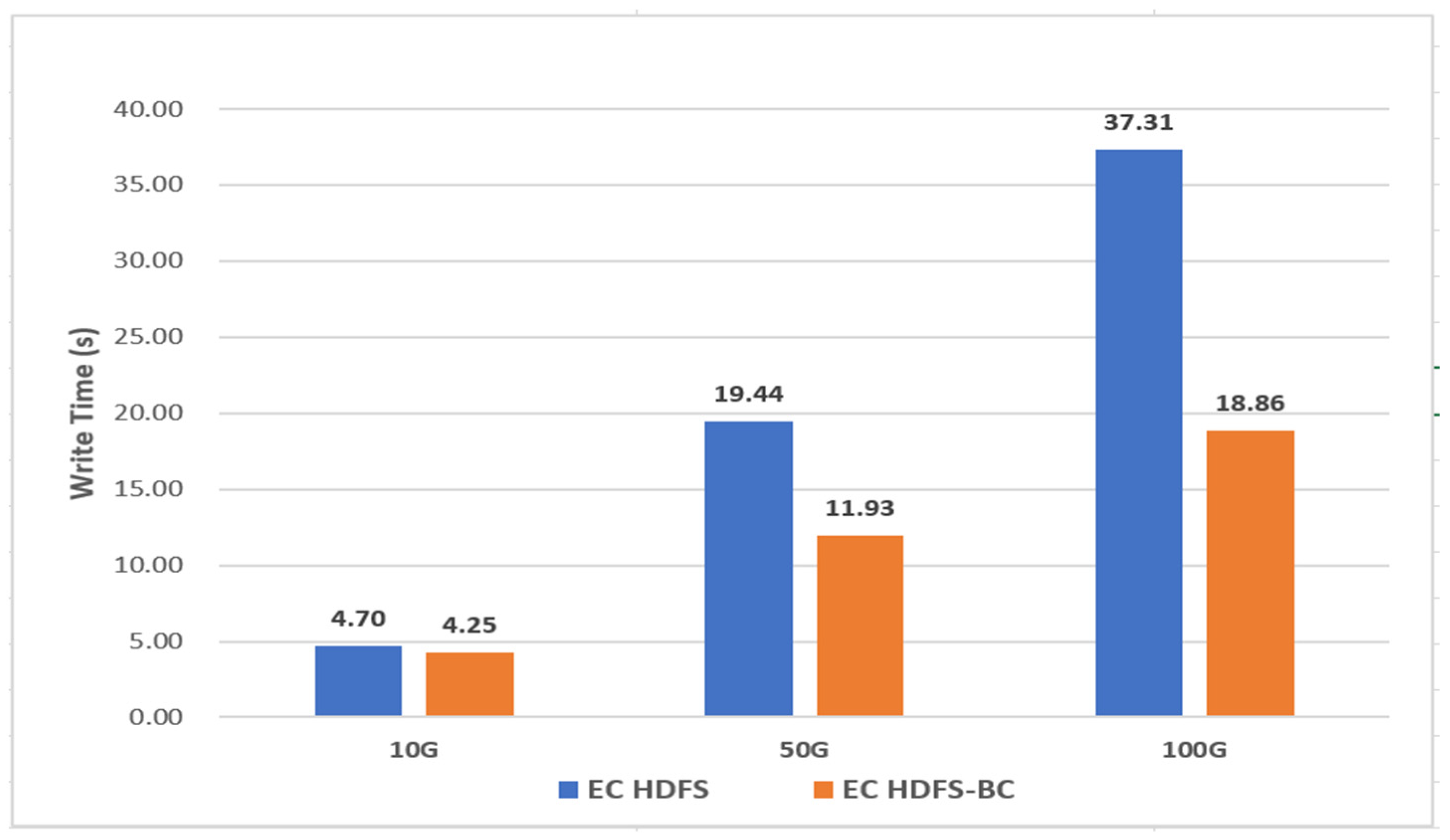
Figure 21 shows a performance comparison when storing sample data with different sizes in the EC HDFS and EC HDFS-BC systems. No significant difference was exhibited when storing 10 GB data, and when storing 50 GB data, the EC HDFS-BC system stored data about 1.3 times faster than the existing EC HDFS. When storing 100 GB data, the storage time of EC HDFS-BC was about twofold faster. The above experiment results show that if larger-size data are stored, more stark difference in storage time would be expected.
6.2. Data Recovery Performance
The data recovery performance was compared between the basic EC-based HDFS and disk I/O load distribution and random block placement and the matrix recycle-applied EC based HDFS, which was proposed in this study. The I/O load distribution technique-applied EC-based HDFS was named EC HDFS-LR (load reducing).
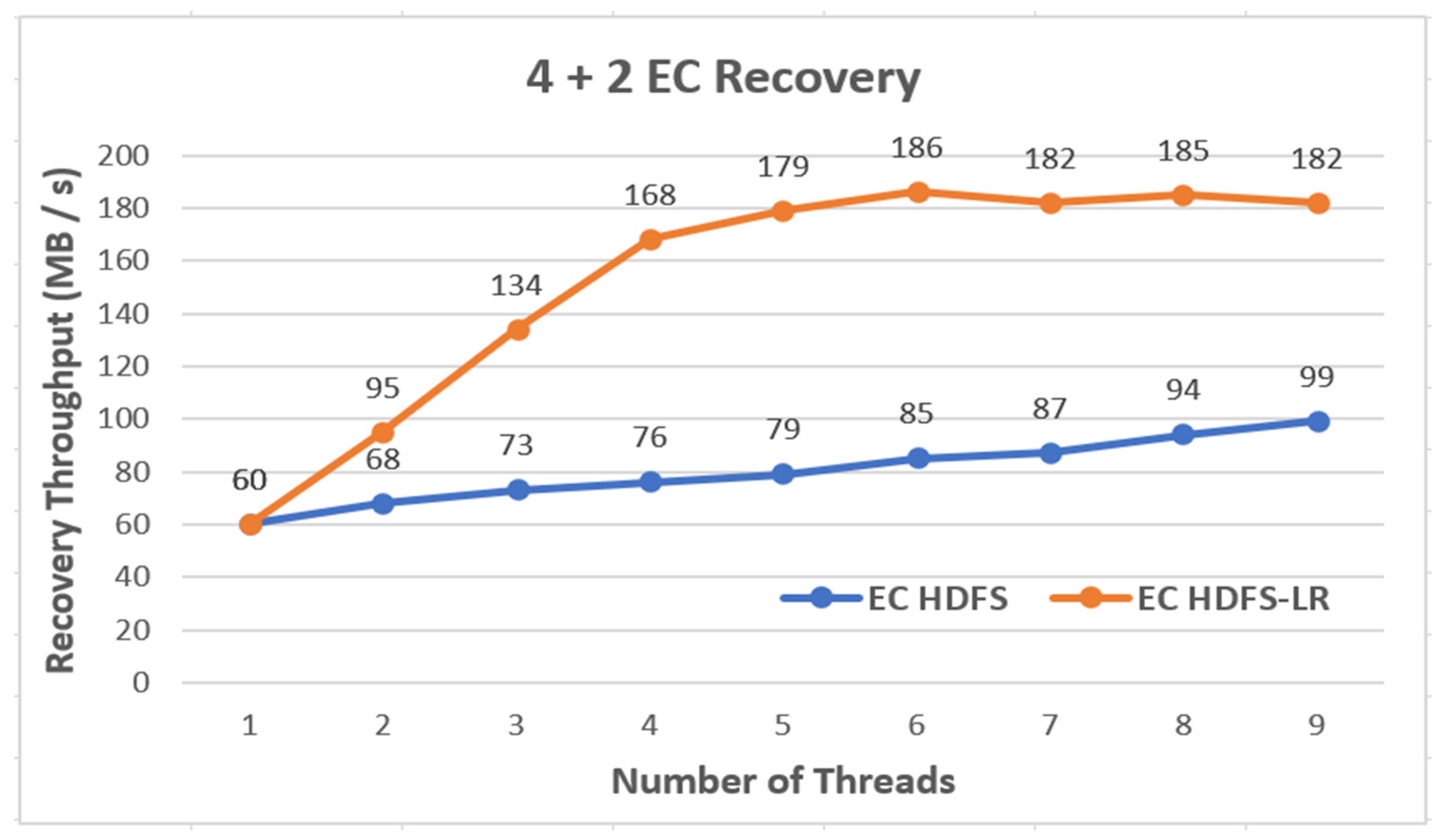
In the experiment, all file systems employed the same 4 + 2 EC volume, and the recovery performance according to changes in recovery threads was measured when one disk failed. In addition, the EC HDFS and EC HDFS-LR employed nonclustering block placement using the round robin algorithm when placing the blocks.
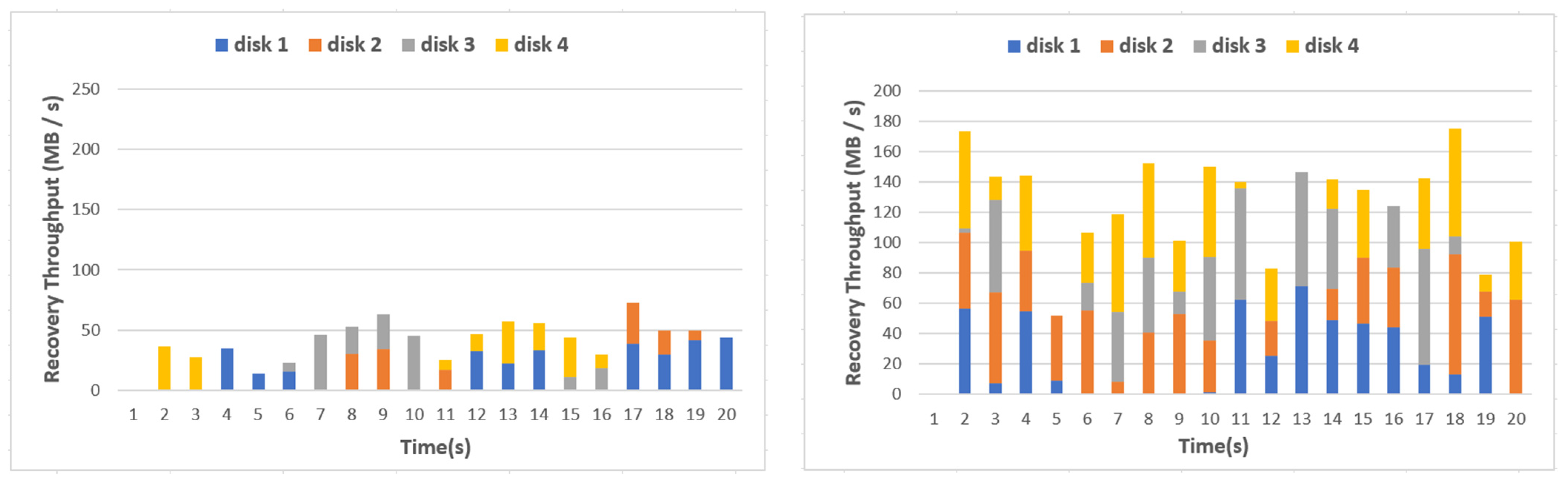
As shown in Figure 22, the performance of EC HDFS was slightly improved as the number of recovery threads increased. The performance of the EC HDFS-LR was rapidly improved until the number of recovery threads was five, which started the reduction of improvement, and after six threads, the performance did not improve. However, the performance of the EC HDFS-LR was about two times better than that of the EC HDFS. Figure 23 shows the disk usage in a specific DataNode when running six recovery threads in the EC HDFS and in the EC HDFS-LR.
As shown in Figure 23, the recovery performance was 50 MB/s on average in the EC HDFS, whereas more disks were utilized in the recovery than that of the EC HDFS. Thus, the recovery performance of the EC HDFS-LR was around 180 MB/s, which was 2.5 times larger than that of the EC HDFS.
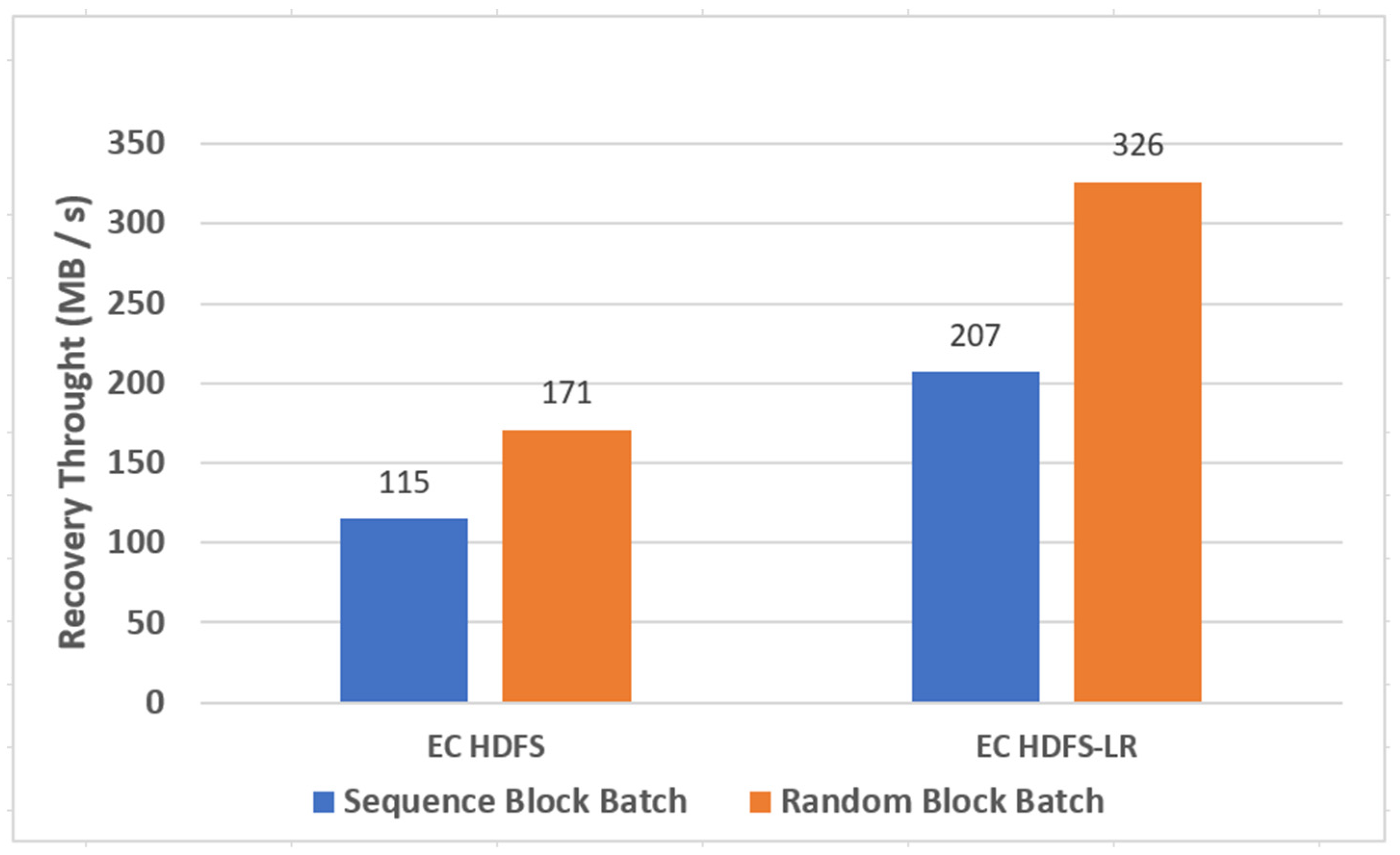
Figure 24 shows the performance comparison when applying the sequential and random block placement techniques to the EC HDFS and EC HDFS-LR. When applying the sequential block placement, performance was improved by about 40% compared with that of applying the random block placement. In particular, when the random block placement was applied to the EC HDFS-LR, the performance was improved further.
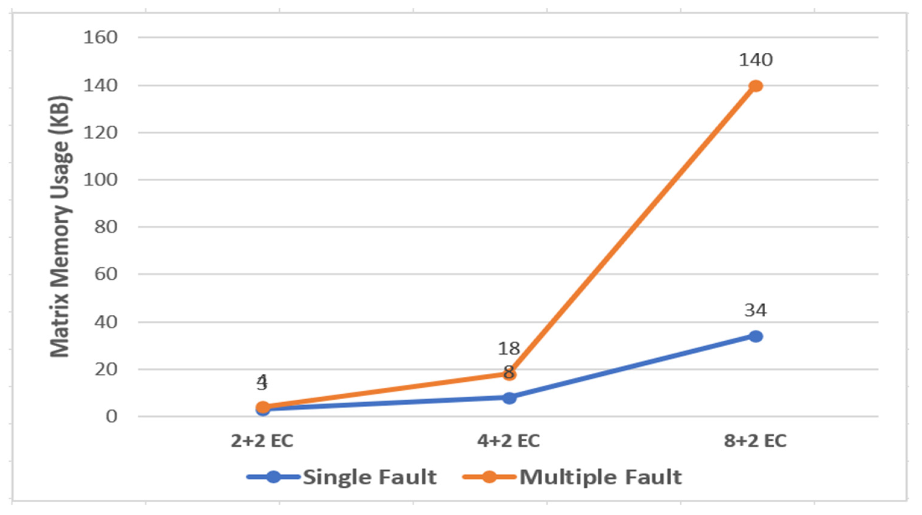
Figure 25 shows the memory usage when single and multiple faults occur in 2 + 2 EC, 4 + 2 EC, and 8 + 2 EC, while the matrix recycle technique is applied and the encoding and decoding word size is set to 32 bytes. Here, single fault means that a fault occurs in only one data cell, and multiple faults mean that faults occur in two data cells simultaneously.
The memory size in the structure where the K + M EC volume is used increases as the K value increases. The memory size used increases as the number of faults increases in the same EC attributes, because the number of used matrices becomes large. However, the used memory size is 140 KB in the 8 + 2 EC volume structure. That is, a severe problem does not occur even if matrices are recycled in the matrix pool because the matrix size is small.
Figure 26 shows the results of 100,000 fault recoveries when one disk fault and two disk faults occur randomly in the 4 + 2 EC volume structure.
When a single disk fault occurred, 100,000 repetitions of fault recovery were performed, and the recovery time when recycling the matrices was about 2.6 times faster. When two disk faults occurred, 100,000 repetitions of fault recovery were performed, and the recovery time when recycling the matrices was about three times faster. That is, a faster recovery time can be ensured if two or more disk faults occur and the volume of the EC system is set to large.
7. Conclusions
Because the EC-based distributed file system among various storage technologies stores data cells by creating and storing parity cells through encoding, it has high space efficiency compared with replication methods. However, the EC-based distributed file system significantly degrades the performance because of disk I/O loads occurring when storing files and a large number of block accesses when recovering files.
Thus, this study selected the HDFS, one of the EC-based distributed file systems, and proposed efficient file storage and recovery methods. The buffering and combining techniques were utilized in file storage, thereby improving the performance about 2.5-fold compared with that of existing HDFSs. For file recovery, performance improved about 2-fold by utilizing disk I/O load distribution, random block placement, and matrix recycle technique.
Funding
This research received no external funding.
Institutional Review Board Statement
Not applicable.
Informed Consent Statement
Not applicable.
Data Availability Statement
Not applicable.
Conflicts of Interest
The authors declare no conflict of interest.
References
- Nicloe, H. An Exascale Timeline for Storage and I/O Systems. Available online: https://www.nextplatform.com/2017/08/16/exascale-timeline-storage-io-systems/ (accessed on 6 April 2021).
- Kunkel, J.M.; Kuhn, M.; Ludwig, T. Exascale storage systems—An analytical study of expenses. Supercomput. Front. Innov. 2014, 1, 116–134. [Google Scholar]
- Bergman, K.; Borkar, S.; Campbell, D.; Carlson, W.; Dally, W.; Denneau, M.; Franzon, P.; Harrod, W.; Hill, K.; Hiller, J.; et al. ExaScale Computing Study: Technology Challenges in Achieving Exascale Systems; DARPA IPTO: Arlington, VA, USA, 2018; p. 15. [Google Scholar]
- Ceph Storage Cluster. Available online: http://docs.ceph.com/docs/master/rados/ (accessed on 6 April 2021).
- Huang, C.; Simitci, H.; Xu, Y.; Ogus, A.; Calder, B.; Gopalan, P.; Li, J.; Yekhanin, S. Erasure coding in windows azure storage. In Proceedings of the USENIX Annual Technical Conference, Boston, MA, USA, 13–15 June 2012; pp. 15–26. [Google Scholar]
- Red Hat Gluster Storage. Available online: https://access.redhat.com/products/red-hat-storage/ (accessed on 6 April 2021).
- Apache Hadoop 3.0.0. Available online: http://hadoop.apache.org/docs/r3.0.0-alpha4 (accessed on 6 April 2021).
- Chun, B.G.; Dabek, F.; Haeberlen, A.; Sit, E.; Weatherspoon, H.; Kaashoek, M.F.; Kubiatowicz, J.; Morris, R. Efficient replica maintenance for distributed storage systems. In Proceedings of the 3rd Symposium on Networked Systems Design & Implementation, San Jose, CA, USA, 8–10 May 2006. [Google Scholar]
- Erasure Coding Support inside HDFS. Available online: https://issues.apache.org/jira/browse/HDFS-7285 (accessed on 6 April 2021).
- Cook, J.D.; Primmer, R.; de Kwant, A. Compare cost and performance of replication and erasure coding. Hitachi Rev. 2014, 63, 304. [Google Scholar]
- Sathiamoorthy, M.; Asteris, M.; Papailiopoulos, D.; Dimakis, A.G.; Vadali, R.; Chen, S.; Borthakur, D. Xoring elephants: Novel erasure codes for big data. Proc. VLDB Endow. 2013, 6, 325–336. [Google Scholar] [CrossRef]
- Rodrigues, R.; Liskov, B. High availability in DHTs: Erasure coding vs. replication. In Proceedings of the International Workshop on Peer-to-Peer Systems, Ithaca, NY, USA, 24–25 February 2005; pp. 226–239. [Google Scholar]
- Erasure Code Support, Sheepdog Wiki. Available online: https://github.com/sheepdog/sheepdog/wiki/Erasure-Code-Support (accessed on 6 April 2021).
- Li, J.; Li, B. Erasure coding for cloud storage systems: A survey. Tsinghua Sci. Technol. 2013, 18, 259–272. [Google Scholar] [CrossRef]
- Li, R.; Zhang, Z.; Zheng, K.; Wang, A. Progress Report: Bringing Erasure Coding to Apache Hadoop. Cloudera Engineering Blog. Available online: http://blog.cloudera.com/blog/2016/02/progress-report-bringing-erasure-coding-to-apache-hadoop/ (accessed on 6 April 2021).
- Plank, J.S.; Simmerman, S.; Schuman, C.D. Jerasure: A Library in C/C++ Facilitating Erasure Coding for Storage Applications; Technical Report No. CS-08-627; University of Tennessee: Knoxville, TN, USA, 2008; p. 23. [Google Scholar]
- Plank, J.S. Erasure codes for storage systems. Usenix 2013, 38, 44–50. [Google Scholar]
- Esmaili, K.S.; Pamies-Juarez, L.; Datta, A. The CORE Storage Primitive: Cross-Object Redundancy for Efficient Data Repair & Access in Erasure Coded Storage; Cornell University: Ithaca, NY, USA, 2013. [Google Scholar]
- Shenoy, A. The Pros and Cons of Erasure Coding & Replication vs. RAID in Next-Gen Storage Platforms. Available online: http://www.snia.org/sites/default/files/SDC15_presentations/datacenter_infra/Shenoy_The_Pros_and_Cons_of_Erasure_v3-rev.pdf (accessed on 6 April 2021).
- Dustin, B. Red Hat Gluster Storage on Supermicro Storage Servers Powered by Intel Xeon Processors; Super Micro Computer: San Jose, CA, USA, 2017. [Google Scholar]
- Dimakis, A.G.; Godfrey, P.B.; Wu, Y.; Wainwright, M.J.; Ramchandran, K. Network coding for distributed storage systems. IEEE Trans. Inf. Theory 2010, 56, 4539–4551. [Google Scholar] [CrossRef] [Green Version]
- Sun, D.; Xu, Y.; Li, Y.; Wu, S.; Tian, C. Efficient parity update for scaling raid-like storage systems. In Proceedings of the IEEE International Conference on Networking, Architecture and Storage (NAS), Long Beach, CA, USA, 8–10 August 2016; pp. 1–10. [Google Scholar]
- Rashmi, K.V.; Shah, N.B.; Gu, D.; Kuang, H.; Borthakur, D.; Ramchandran, K. A “hitchhiker’s” guide to fast and efficient data reconstruction in erasure-coded data centers. In Proceedings of the ACM Conference on SIGCOMM, Chicago, IL, USA, 17–24 August 2014; pp. 331–342. [Google Scholar]
- Rashmi, K.V.; Shah, N.B.; Gu, D.; Kuang, H.; Borthakur, D.; Ramchandran, K. A solution to the network challenges of data recovery in erasure-coded distributed storage systems: A study on the Facebook warehouse cluster. In Proceedings of the 5th USENIX Workshop on Hot Topics in Storage and File Systems (HotStorage), San Jose, CA, USA, 27–28 June 2013; p. 8. [Google Scholar]
- Mohan, L.J.; Harold, R.L.; Caneleo, P.I.S.; Parampalli, U.; Harwood, A. Benchmarking the performance of hadoop triple replication and erasure coding on a nation-wide distributed cloud. In Proceedings of the International Symposium on Network Coding (NetCod), Sydney, Australia, 22–24 June 2015; pp. 61–65. [Google Scholar]
- Considerations for RAID-6 Availability and Format/Rebuild Performance on the DS5000. Available online: http://www.redbooks.ibm.com/redpapers/pdfs/redp4484.pdf (accessed on 6 April 2021).
- Miyamae, T.; Nakao, T.; Shiozawa, K. Erasure code with shingled local parity groups for efficient recovery from multiple disk failures. In Proceedings of the 10th Workshop on Hot Topics in System Dependability, Broomfield, CO, USA, 5 October 2014. [Google Scholar]
- Luo, X.; Shu, J. Load-balanced recovery schemes for single-disk failure in storage systems with any erasure code. In Proceedings of the 42nd International Conference on Parallel Processing, Lyon, France, 1–4 October 2013. [Google Scholar]
- Ford, D.; Labelle, F.; Popovici, F.I.; Stokely, M.; Truong, V.-A.; Barroso, L.; Grimes, C.; Quinlan, S. Availability in globally distributed storage systems. In Proceedings of the 9th USENIX Conference on Operating Systems Design and Implementation, Vancouver, BC, Canada, 4–6 October 2010. [Google Scholar]
- Muralidhar, S.; Lloyd, W.; Roy, S.; Hill, C.; Lin, E.; Liu, W.; Pan, S.; Shankar, S.; Sivakumar, V.; Tang, L.; et al. F4: Facebook’s warm blob storage system. In Proceedings of the 11th USENIX Symposium on Operating Systems Design and Implementation, Broomfield, CO, USA, 6–8 October 2014. [Google Scholar]
- Facebook’s Realtime Distributed FS Based on Apache Hadoop 0.20-append. Available online: https: //github.com/facebookarchive/hadoop-20 (accessed on 6 April 2021).
- OpenStack Swift. Available online: https://wiki.openstack.org/wiki/Swift (accessed on 6 April 2021).
- Ovsiannikov, M.; Rus, S.; Reeves, D.; Sutter, P.; Rao, S.; Kelly, J. The Quantcast file system. Proc. VLDB Endow. 2013. [Google Scholar] [CrossRef]
- Weil, S.A.; Brandt, S.A.; Miller, E.L.; Long, D.D.; Maltzahn, C. Ceph: A scalable, high-performance distributed file system. In Proceedings of the 7th Symposium on Operating Systems Design and Implementation, Seattle, WA, USA, 6–8 November 2006. [Google Scholar]
- Wilcox-O’Hearn, Z.; Warner, B. Tahoe: The least-authority filesystem. In Proceedings of the 4th ACM International Workshop on Storage Security and Survivability, Alexandria, VA, USA, 31 October 2008. [Google Scholar]
- Reed, I.S.; Solomon, G. Polynomial codes over certain finite fields. J. Soc. Ind. Appl. Math. 1960, 8, 300–304. [Google Scholar] [CrossRef]
- HDFS-RAID. Available online: https://wiki.apache.org/hadoop/HDFS-RAID (accessed on 6 April 2021).
- Wang, W.; Kuang, H. Saving Capacity with HDFS RAID. Available online: https://code.facebook.com/posts/536638663113101/saving-capacity-with-hdfs-raid/ (accessed on 6 April 2021).
- Arnold, J. Erasure Codes with OpenStack Swift Digging Deeper. Available online: https://swiftstack.com/blog/2013/07/17/erasure-codes-with-openstack-swift-digging-deeper/ (accessed on 6 April 2021).
- Zhang, X.; Wang, J.; Yin, J. Sapprox: Enabling efficient and accurate Approximations on sub-datasets with distribution-aware online sampling. Proc. VLDB Endow. 2016, 10, 109–120. [Google Scholar] [CrossRef]
- Wang, J.; Yin, J.; Zhou, J.; Zhang, X.; Wang, R. DataNet: A data distribution-aware method for sub-dataset analysis on distributed file systems. In Proceedings of the IEEE International Parallel and Distributed Processing Symposium, Chicago, IL, USA, 23–27 May 2016. [Google Scholar]
- Chen, Y.; Alspaugh, S.; Katz, R. Interactive analytical processing in big data systems: A cross-industry study of MapReduce workloads. Proc. VLDB Endow. 2012, 5, 1802–1813. [Google Scholar] [CrossRef]
- Papailiopoulos, D.S.; Luo, J.; Dimakis, A.G.; Huang, C.; Li, J. Simple regenerating codes: Network coding for cloud storage. In Proceedings of the IEEE International Conference on Computer Communications, Orlando, FL, USA, 25–30 March 2012. [Google Scholar]
- Papailiopoulos, D.; Dimakis, A. Locally repairable codes. In Proceedings of the IEEE International Symposium on Information Theory Proceedings, Cambridge, MA, USA, 1–6 July 2012. [Google Scholar]
- Oggier, F.; Datta, A. Self-repairing homomorphic codes for distributed storage systems. In Proceedings of the IEEE International Conference on Computer Communications, Shangai, China, 10–15 April 2011. [Google Scholar]
- Huang, C.; Chen, M.; Li, J. Pyramid codes: Flexible schemes to trade space for access efficiency in reliable data storage systems. ACM Trans. Storage 2013, 9. [Google Scholar] [CrossRef]
- Kim, D.O.; Kim, H.Y.; Kim, Y.K.; Kim, J.J. Cost analysis of erasure coding for exa-scale storage. J. Supercomput. 2019, 75, 4638–4656. [Google Scholar] [CrossRef] [Green Version]
- Kim, D.O.; Kim, H.Y.; Kim, Y.K.; Kim, J.J. Efficient techniques of parallel recovery for erasure-coding-based distributed file systems. J. Comput. 2019, 101, 1861–1884. [Google Scholar] [CrossRef]
- Miranda, A.; Effert, S.; Kang, Y.; Miller, E.L.; Popov, I.; Brinkmann, A.; Friedetzky, T.; Cortes, T. Random slicing: Efficient and scalable data placement for large-scale storage systems. ACM Trans. Storage 2014, 10, 9. [Google Scholar] [CrossRef] [Green Version]
- Chu, X.; Liu, C.; Ouyang, K.; Yung, L.S.; Liu, H.; Leung, Y.-W. PErasure: A parallel cauchy reed-solomon coding library for GPUs. In Proceedings of the IEEE International Conference on Communications, London, UK, 8–12 June 2015; pp. 436–441. [Google Scholar]
- Kim, C.Y.; Kim, D.O.; Kim, H.Y.; Kim, Y.K.; Seo, D.W. Torus network based distributed storage system for massive multimedia contents. J. Korea Multimed. Soc. 2016, 19, 1487–1497. [Google Scholar] [CrossRef]
- Mitra, S.; Panta, R.; Ra, M.R.; Bagchi, S. Partial-parallel-repair (PPR): A distributed technique for repairing erasure coded storage. In Proceedings of the 11th European Conference on Computer Systems, London, UK, 18–21 April 2016; pp. 1–16. [Google Scholar]
- Liu, C.; Chu, X.; Liu, H.; Leung, Y.W. ESet: Placing data towards efficient recovery for large-scale erasure-coded storage systems. In Proceedings of the 25th International Conference on Computer Communication and Networks (ICCCN), Waikoloa, HI, USA, 1–4 August 2016; pp. 1–9. [Google Scholar]
- Xia, M.; Saxena, M.; Blaum, M.; Pease, D.A. A tale of two erasure codes in HDFS. In Proceedings of the 13th USENIX Conference on File and Storage Technologies, Santa Clara, CA, USA, 16–19 February 2015; pp. 213–226. [Google Scholar]
- Fu, Y.; Shu, J.; Luo, X. A stack-based single disk failure recovery scheme for erasure coded storage systems. In Proceedings of the IEEE 33rd international Symposium on Reliable Distributed Systems, Nara, Japan, 6–9 October 2014; pp. 136–145. [Google Scholar]
Figure 1.
Single input/output (I/O) process in erasure coding (EC)-based Hadoop distributed file system (HDFS).
Figure 1.
Single input/output (I/O) process in erasure coding (EC)-based Hadoop distributed file system (HDFS).

Figure 2.
Multiple I/O process in the EC-based HDFS.

Figure 3.
Process of distributing blocks in the EC-based HDFS system.

Figure 4.
Examples of clustering (left) and nonclustering (right) storage modes.

Figure 5.
Disk usage in DataNode 1 during single-thread fault recovery.

Figure 6.
Disk usage in DataNode 1 during multithread fault recovery.

Figure 7.
I/O buffering step.

Figure 8.
Method in the I/O buffering step.

Figure 9.
I/O combining step.

Figure 10.
Method in the I/O combining step.

Figure 11.
I/O combining algorithm.

Figure 12.
Example of disk loads due to parallel recovery.

Figure 13.
Disk I/O load distribution algorithm.

Figure 14.
Example of disk contention avoidance due to parallel recovery.

Figure 15.
Rules for creating a new block.

Figure 16.
Examples of sequential (left) and random (right) block placement disk fault.

Figure 17.
Case where matrices differ in a single fault.

Figure 18.
Data structure to compose the matrix.

Figure 19.
Matrix recycle step.

Figure 20.
Comparison between EC-based HDFS and improvement-applied performances.

Figure 21.
Difference in storage time according to file size.

Figure 22.
Comparison of recovery performance according to the number of recovery threads.

Figure 23.
Disk usage of the EC HDFS (left) and the EC HDFS-LR (right).

Figure 24.
Performance comparison according to the block placement technique between the EC HDFS and the EC HDFS-LR.
Figure 24.
Performance comparison according to the block placement technique between the EC HDFS and the EC HDFS-LR.

Figure 25.
Memory size (KB) needed for matrix storage.

Figure 26.
Performance comparison according to the matrix recycle.


Table 1.
The 128 KB I/O process size in the DataNode according to the EC setting.
| EC Volume DataNode | 2 + 2 | 4 + 2 | 8 + 2 | 16 + 2 |
|---|---|---|---|---|
| DataNode I/O size | 64 KB | 32 KB | 16 KB | 8 KB |
| DataNode I/O count | 4 | 6 | 10 | 18 |
Table 2.
Combining process scale for 16 128 KB-sized requests in the 16 + 2 EC volume.
| 128 KB Request Count Combine | 1 | 2 | 4 | 8 | 16 |
|---|---|---|---|---|---|
| Combine I/O size | 8 KB | 16 KB | 32 KB | 64 KB | 128 KB |
| Combine I/O count | 288 | 144 | 72 | 36 | 18 |
Table 3.
Number of matrices required for decoding according to EC attributes.
| EC K + M Volume | M = 1 | M = 2 |
|---|---|---|
| K = 2 | 3 | 6 |
| K = 4 | 5 | 15 |
| K = 8 | 9 | 45 |
| K = 16 | 17 | 153 |
Publisher’s Note: MDPI stays neutral with regard to jurisdictional claims in published maps and institutional affiliations. |
© 2021 by the author. Licensee MDPI, Basel, Switzerland. This article is an open access article distributed under the terms and conditions of the Creative Commons Attribution (CC BY) license (https://creativecommons.org/licenses/by/4.0/).
Share and Cite
MDPI and ACS Style
Kim, J.-J. Erasure-Coding-Based Storage and Recovery for Distributed Exascale Storage Systems. Appl. Sci. 2021, 11, 3298. https://doi.org/10.3390/app11083298
AMA Style
Kim J-J. Erasure-Coding-Based Storage and Recovery for Distributed Exascale Storage Systems. Applied Sciences. 2021; 11(8):3298. https://doi.org/10.3390/app11083298
Chicago/Turabian StyleKim, Jeong-Joon. 2021. "Erasure-Coding-Based Storage and Recovery for Distributed Exascale Storage Systems" Applied Sciences 11, no. 8: 3298. https://doi.org/10.3390/app11083298
Note that from the first issue of 2016, this journal uses article numbers instead of page numbers. See further details here.