Article

Kinematic Modelling and Motion Analysis of a Humanoid Torso Mechanism

1
Faculty of Engineering, University of Nottingham, Nottingham NG81BB, UK
2
LARM2: Laboratory of Robot Mechatronics, University of Rome “Tor Vergata”, 00133 Rome, Italy
3
Biomechatronics Lab, IRCCS Neuromed, 86077 Pozzilli, Italy
*
Author to whom correspondence should be addressed.
Appl. Sci. 2021, 11(6), 2607; https://doi.org/10.3390/app11062607
Submission received: 1 March 2021 / Revised: 12 March 2021 / Accepted: 12 March 2021 / Published: 15 March 2021
(This article belongs to the Special Issue Innovative Robot Designs and Approaches)

Abstract

:

Featured Application

Model-based motion planning of cable-driven compliant mechanisms with a flexible backbone.

Abstract

This paper introduces a novel kinematic model for a tendon-driven compliant torso mechanism for humanoid robots, which describes the complex behaviour of a system characterised by the interaction of a complex compliant element with rigid bodies and actuation tendons. Inspired by a human spine, the proposed mechanism is based on a flexible backbone whose shape is controlled by two pairs of antagonistic tendons. First, the structure is analysed to identify the main modes of motion. Then, a constant curvature kinematic model is extended to describe the behaviour of the torso mechanism under examination, which includes axial elongation/compression and torsion in addition to the main bending motion. A linearised stiffness model is also formulated to estimate the static response of the backbone. The novel model is used to evaluate the workspace of an example mechanical design, and then it is mapped onto a controller to validate the results with an experimental test on a prototype. By replacing a previous approximated model calibrated on experimental data, this kinematic model improves the accuracy and efficiency of the torso mechanism and enables the performance evaluation of the robot over the reachable workspace, to ensure that the tendon-driven architecture operates within its wrench-closure workspace.

1. Introduction

Mobile robots are often limited in their tasks by an environment designed to be inhabited by humans. A wheeled robot, for example, cannot climb stairs, while an animal-like robot, such as hexapods or quadrupeds, is often stopped by a closed door. Conversely, humanoid robots can interact with human-sized items and navigating in human-sized environments. Furthermore, people tend to react better to humanoid robots than to other architectures [1].
Most humanoid robots are developed to optimise their limb mobility with a “black box” approach, in which the locomotion system is developed independently from the manipulation system and then integrated only through control software. Thus, complex leg and arm designs can be found in the literature [2], whereas the robot torso usually consists of a single body with no mobility. This kind of architecture can be observed in the most successful humanoid robots, including Honda’s ASIMO [3], University of Waseda’s WABIAN family [4], and Softbank’s NAO [5] and Pepper [6].
However, the human torso plays a key role in both locomotion and manipulation tasks, by supporting dynamic balance and increasing reach and dexterity [7,8,9]. Thus, recent humanoid robot designs have started introducing torso motion control [10] or one or more degrees of mobility in the torso to enhance performance. These designs range from simple serial mechanisms [11,12,13] to parallel architectures [14,15,16], which have demonstrated how much torso mobility can improve robot performance.
Among these robots, the LARMbot humanoid [17,18,19,20] is equipped with a cable-driven compliant torso mechanism with a complex behaviour inspired by the human spine: a central compliant element represents the backbone; actuated cables act as muscle tendons to define the shape of the central element, and rigid disk-like vertebrae route the cables in parallel to the backbone [15].
In previous studies, the behaviour of this mechanism has been numerically determined by linearly interpolating motion calibration data experimentally [16]. However, while a satisfying performance can be obtained with this procedure, the result is limited to a specific design and geometry and high precision can be ensured only in a limited motion range. Conversely, a model-based control would ensure correct behaviour of the mechanism over its whole range of motion and for any given geometry.
While an analytical kinematic model would significantly improve torso performance, modelling the complex cable-driven compliant mechanism poses several challenges. While hybrid mechanisms with a rigid joint in parallel to two or more actuation cables have been kinematically modelled in the past [21,22], previous results can only be partially applied to the proposed mechanism due to the increased mobility and compliance of the compliant backbone, which is capable of three main motion modes: bending, compression, and axial torsion.
A solution to this can be found in continuum and snake-like robot literature. These systems are characterised by a compliant backbone with bending capabilities [23,24] that are described through constant [25] or variable [26,27] curvature kinematics. These models use two variables to define the bending mode, namely bending angle and direction of the bending plane, and they are also capable of describing backbone elongation [28].
In this paper, an extension of the constant curvature kinematic model which includes torsion and elongation is proposed as a novel solution to define a kinematic model that accurately describes the complex behaviour of the LARMbot’s torso mechanism. First, the mechanical design of the torso is introduced with its main constructive details. Then, the behaviour of the different components of the system—tendons, compliant backbone, and rigid disks—is kinematically modelled to obtain a closed-form solution for an efficient control system. Finally, the model is validated with numerical results.

2. Materials and Methods

In this section, the architecture of the LARMbot’s torso mechanism is briefly introduced with its main constructive elements and its functioning. Then, the mechanism’s behaviour is modelled with a constant curvature model to describe its bending compliance, expanded to include both backbone torsion and compression due to cable tension. The proposed model achieves a closed-form analytical formulation for the robot kinematics, for accurately and efficiently controlling the system as well as enabling a complete characterization of its behaviour.

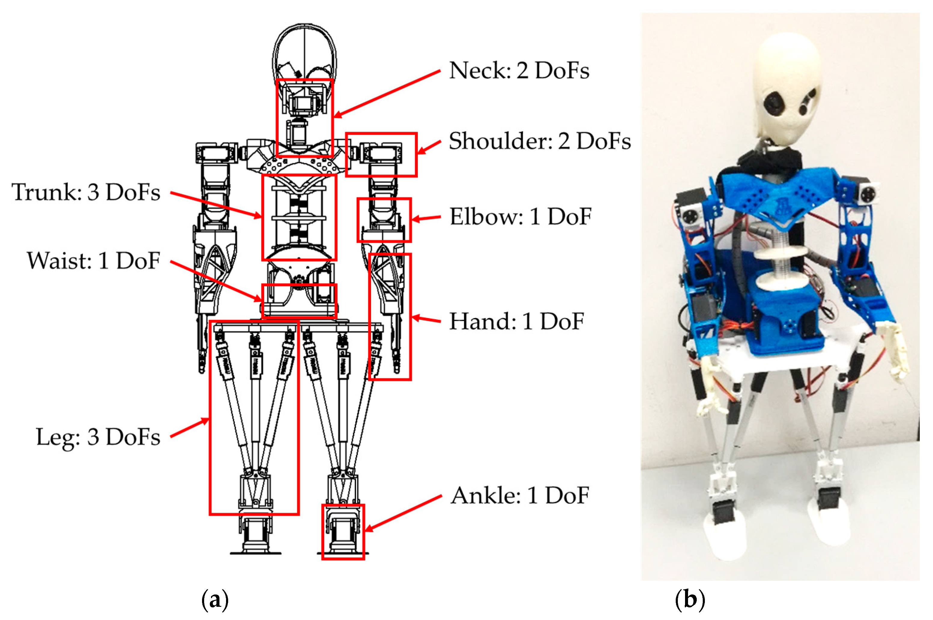
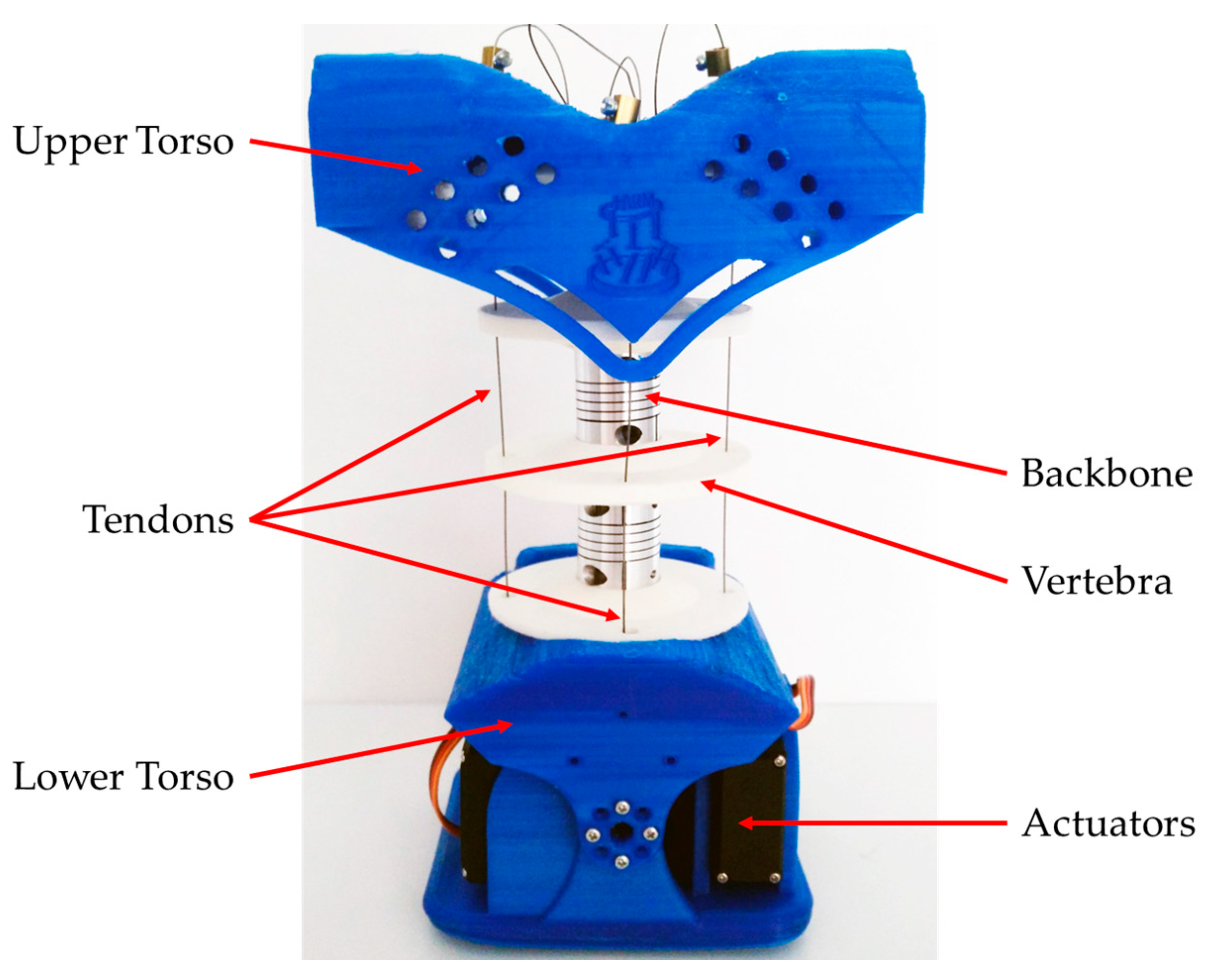
2.1. Mechanical Design of LARMbot’s Torso Mechanism

The LARMbot humanoid robot was developed between 2012 and 2018 [15,16,17,18,19,20] at the LARM laboratory of the University of Cassino. It was designed as a low-cost user-friendly humanoid robot for service tasks, and it features parallel mechanisms both in its legs [29] and torso [30] to achieve a high kinematic and dynamic performance.
As shown in Figure 1, this humanoid robot is characterised by 22 active degrees of freedom (DoFs), a height of 850 mm, and an overall mass of 3.600 kg only, thanks to its lightweight 3D-printed frame [17]. Its torso mechanism, CAUTO (CAssino hUmanoid TOrso), is bioinspired, reproducing Functional Spine Units (FSU). The torso is at the core of the LARMbot performance, as it contributes to both walking balance, general navigation, and manipulation tasks thanks to the additional three active DoFs that it provides to the system. The main geometrical parameters of this mechanism are reported in Table 1, while the main components are illustrated on a 3D-printed prototype in Figure 2.
The main structural element of the torso is the compliant backbone, made of commercial flexible shaft couplers that are characterised by a compliant response to bending and a stiffer response to axial torsion, compression, and elongation. As these components connect the rigid vertebrae of the spine, they determine the mobility of the system. The intrinsic stiffness of the backbone also dampens the effect of unexpected wrenches on the system and restores a straight torso position in case of structural failure of the tendons. The configuration of the couplers is actuated by four tendons that determine the pose of the upper torso with respect to the lower torso.

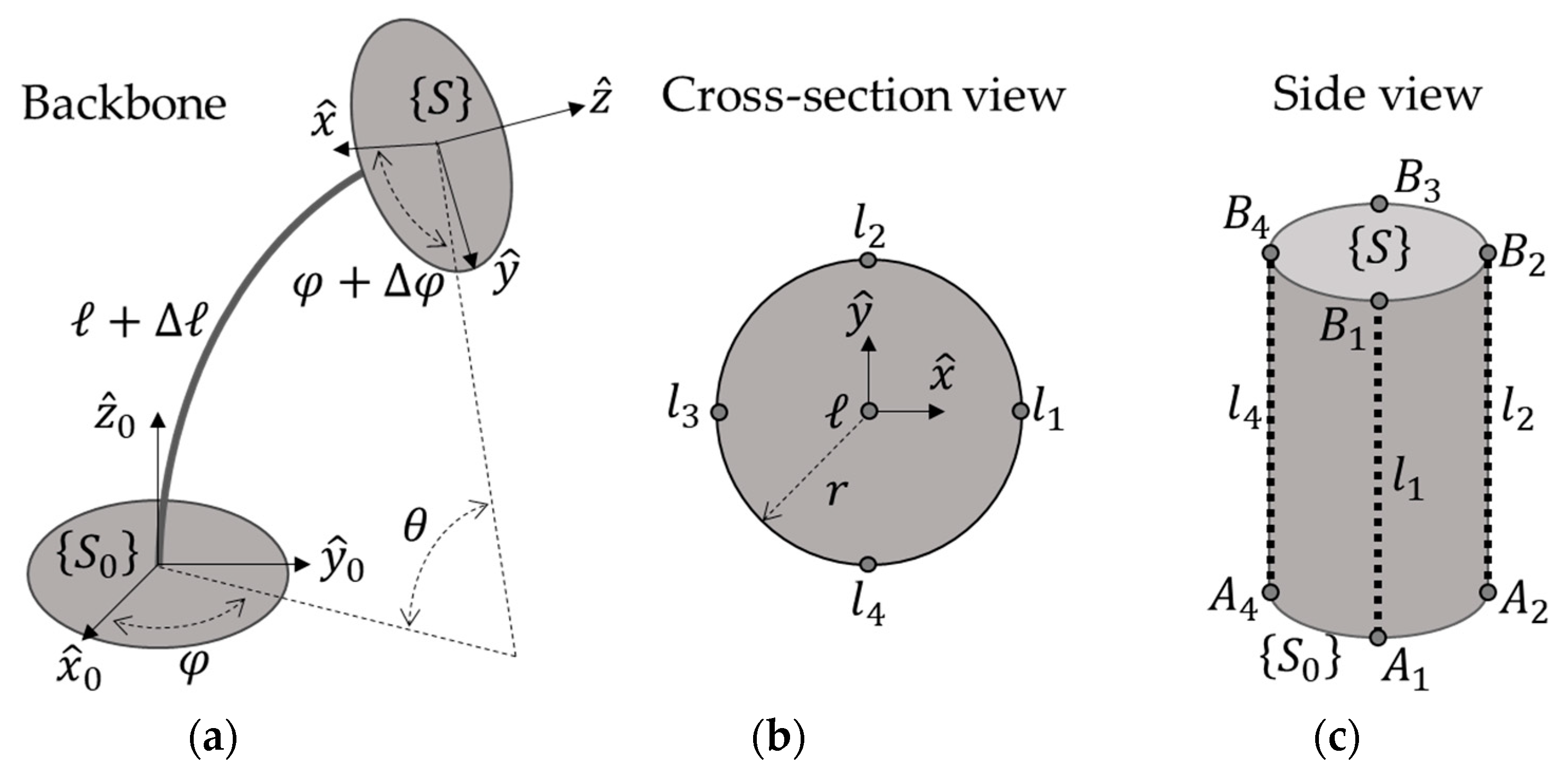
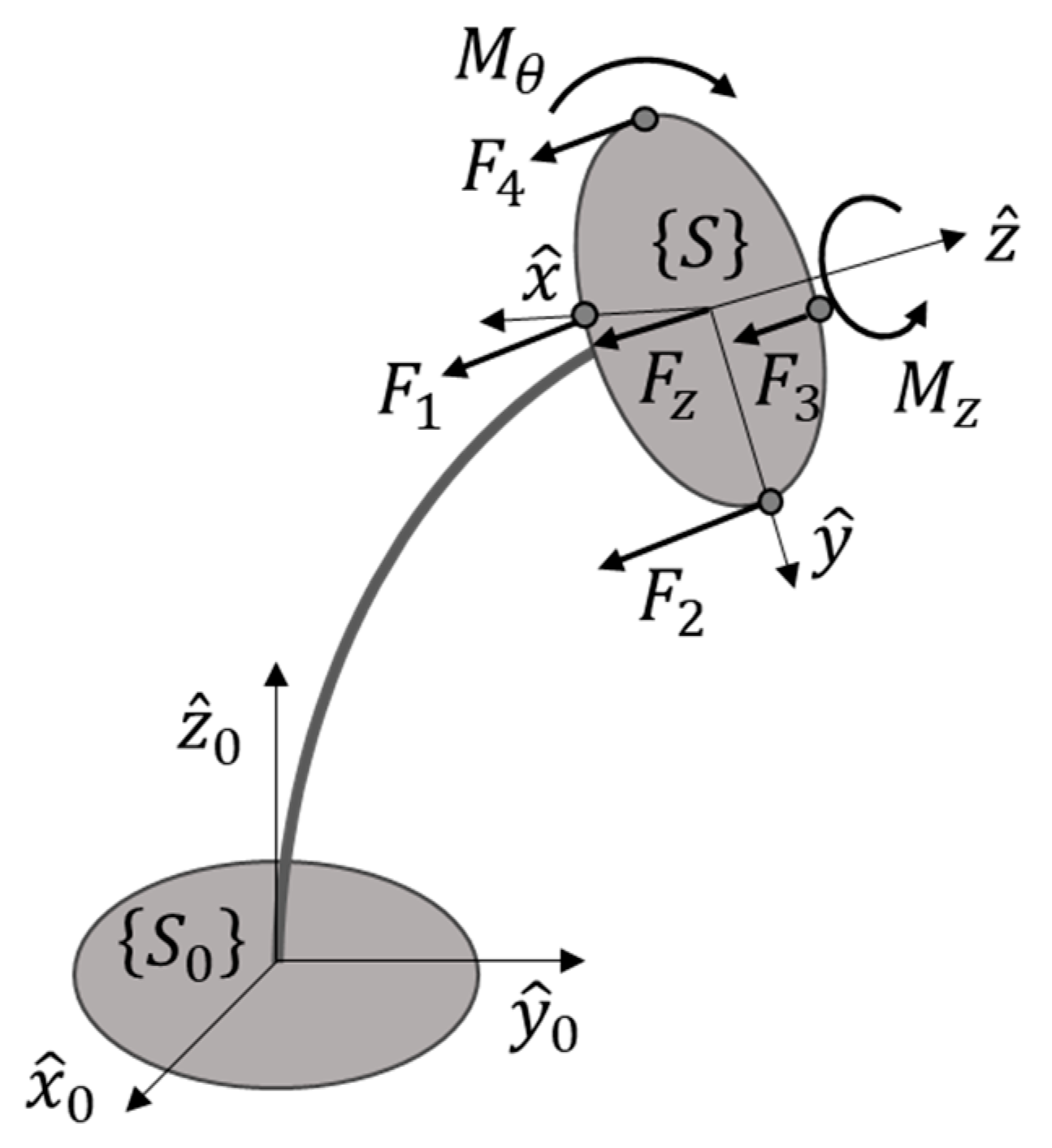
2.2. Kinematic Modelling of a Compliant Tendon-Driven Torso Mechanism

When compared to other similar tendon-driven mechanisms with four cables driving a joint, such as the rehabilitation device in [22], the LARMbot’s torso mechanism poses additional challenges due to the compliance of the backbone. First, the backbone is not an idle joint, and, because of its stiffness, it exerts a wrench on the upper platform in any non-straight configuration. This wrench results in a higher actuation force required to move the torso mechanism but improves the dynamic behaviour of the mechanism by restoring a stable position when force closure is not achieved [22]. Furthermore, the torso mechanism, which is illustrated in the kinematic scheme in Figure 3, is also characterised by a degree of underactuation.
The backbone has four DoFs, which can be characterised by the following parameters with reference to the kinematic schemes in Figure 3:
  • Backbone bending angle θ , which is defined as the angle between the x0y0 plane of the lower torso frame {S0} and the xy plane of the upper torso frame {S}.
  • Direction of bending φ , which is defined as the angle between the plane of bending and the x0y0 plane of the lower torso frame {S0}.
  • Axial torsion φ , which is defined as the angle between the x0z0 plane of the lower torso frame {S0} and the xz plane of the upper torso frame {S}.
  • Axial elongation/compression , which is defined as the variation of the neutral backbone length caused by the wrench acting on the component.
However, only three of these DoFs can be actively controlled by the four actuators, as the tendons (routed as per Figure 3b,c) can only pull, but not push [22]. Thus, the configuration of the mechanism cannot be determined with motor position only, as its torsional mobility is underactuated and depends on the passive spring-like elements in the system, that is, the torso’s backbone. Thus, kinematics must be integrated with a stiffness model of the backbone for complete characterization.
As previously mentioned, a piecewise constant curvature kinematic (PCCK) model is used to describe the main bending of the backbone. PCCK models have been conceived as a convenient tool to analyse and control continuum robots, as explained in [25], even though they are recently being replaced by more complex models with variable curvature [26,27] to accurately describe the hyper-redundant architecture of those systems, with complex motion coupling between independently bending sections. However, as the proposed torso mechanism can be represented by a single bending section, a constant curvature model can appropriately model the compliant backbone with limited approximation errors. To describe the pose of the lower and upper torso, the reference frames {S0} and {S} can be defined at the base and at the end of the backbone, respectively. By assuming constant curvature along the backbone, the translation along its central curve t 3 can be expressed by an arc of a circle as:
t ( θ , φ , ) = + θ [ cos φ ( 1 cos θ ) sin φ ( 1 cos θ ) sin θ ] ,
while the rotation from {S0} to {S} can be written as a rotation matrix R S O ( 3 ) that is:
R ( θ , φ , φ ) = R z ( φ ) · R y ( θ ) R z ( φ φ ) ,
where R z ( φ ) represents a rotation of φ around the z-axis, R y ( θ ) represents a rotation of θ around the y-axis, and R z ( φ φ ) represents a rotation of φ φ around the z-axis. These equations expand the conventional PCCK that is described in [25] to include both the elongation/compression and the axial torsion that are characteristic of the mechanism under examination. The forward kinematics of the torso mechanism can be thus defined with the homogeneous transformation T S E ( 3 ) from {S0} to {S} as:
T ( θ , φ , , φ ) = [ R ( θ , φ , φ ) t ( θ , φ , ) 0 1 ] .
Equation (3) represents only the first part of the kinematics of the structure, as it relates the pose of the upper torso (with respect to the lower torso) only to its configuration, not to the length of the actuating tendons. To compute tendon length l = ( l 1 ;   l 2 ;   l 3 ;   l 4 ) T , the four tendons can be modelled as circle arcs that bend in parallel to the backbone, with the same bending angle and direction. Thus, their lengths can be evaluated as:
l i = + + θ r cos ( φ + φ + ( i 1 ) π 2 ) ; i = { 1 ,   2 ,   3 ,   4 } .
By using Equations (3) and (4), the relationship between actuation vector l and upper platform pose T can be obtained, defining the kinematic input-output function of the robotic system. However, as previously mentioned, the stiffness of the backbone must be considered for full characterization. In order to do so, a linear elastic behaviour of the backbone is assumed, with a torsional stiffness k t , a compression module of k c , and a bending stiffness k b that can be evaluated from the material properties and are related to motion parameters as:
M z = k t φ ;   F z = k c ;   M θ = k b θ ,
where M z is the moment around the z-axis of the backbone, representing axial torsion; F z is the force along the z-axis of the backbone, representing compression; and M θ = M y sin φ M x cos φ is the bending moment acting on the backbone, which can be written as a combination of the moments around the x- and y-axes of the backbone, M x and M y . Given the tensions in the tendons F 1 , F 2 , F 3 , and F 4 , these values can be computed as:
M x = ( F 2 F 4 ) r ;   M y = ( F 3 F 1 ) r ;   M θ = M y sin φ M x cos φ ;   F z = i = 1 4 F i .
Thus, as expressed in Equation (6) and with reference to Figure 4, the four actuation cables can actively control the two DoFs related to bending, whereas the compression/elongation and torsion of the backbone are coupled and cannot be actuated independently.
If a general external wrench ( P x ;   P y ;   P z ;   W x ;   W y ;   W z ) T is applied to the upper torso, the elongation and torsion of the backbone can be estimated from:
M x = ( F 2 F 4 ) r + + θ ( P z sin φ ( 1 cos θ ) P y sin θ ) + W x ;   M y = ( F 3 F 1 ) r + + θ ( P x sin θ P z cos φ ( 1 cos θ ) ) + W y ;   F z = P z + i = 1 4 F i ;
and decoupled through a pose measurement with an onboard motion sensor (for example, with the Inertial Measurement Unit (IMU) installed on the LARMbot’s upper torso).
In summary, the model in this section can be used to accurately move the CAUTO torso by integrating the feedback from the motors’ sensors and the IMUs on the upper torso and the head of the humanoid robot to enable closed-loop control.

3. Results

The kinematic model defined in the previous section is here used to evaluate the workspace of the torso mechanism and its characteristics. Furthermore, a simple mapping of the kinematic variables to an input joystick device is discussed for smooth motion planning with experimental validation of a prototype moving in the torso’s workspace that is evaluated with the proposed model.

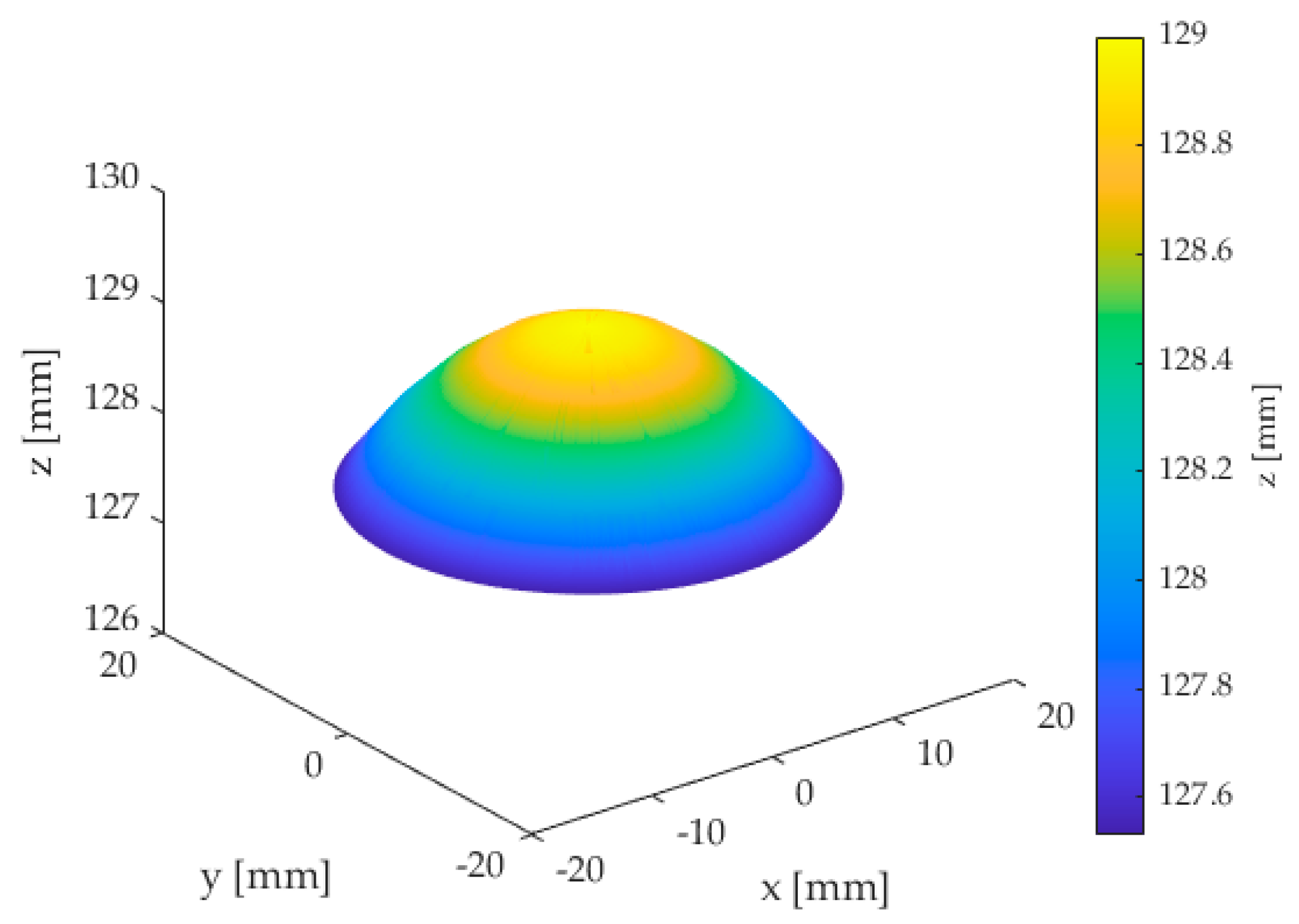
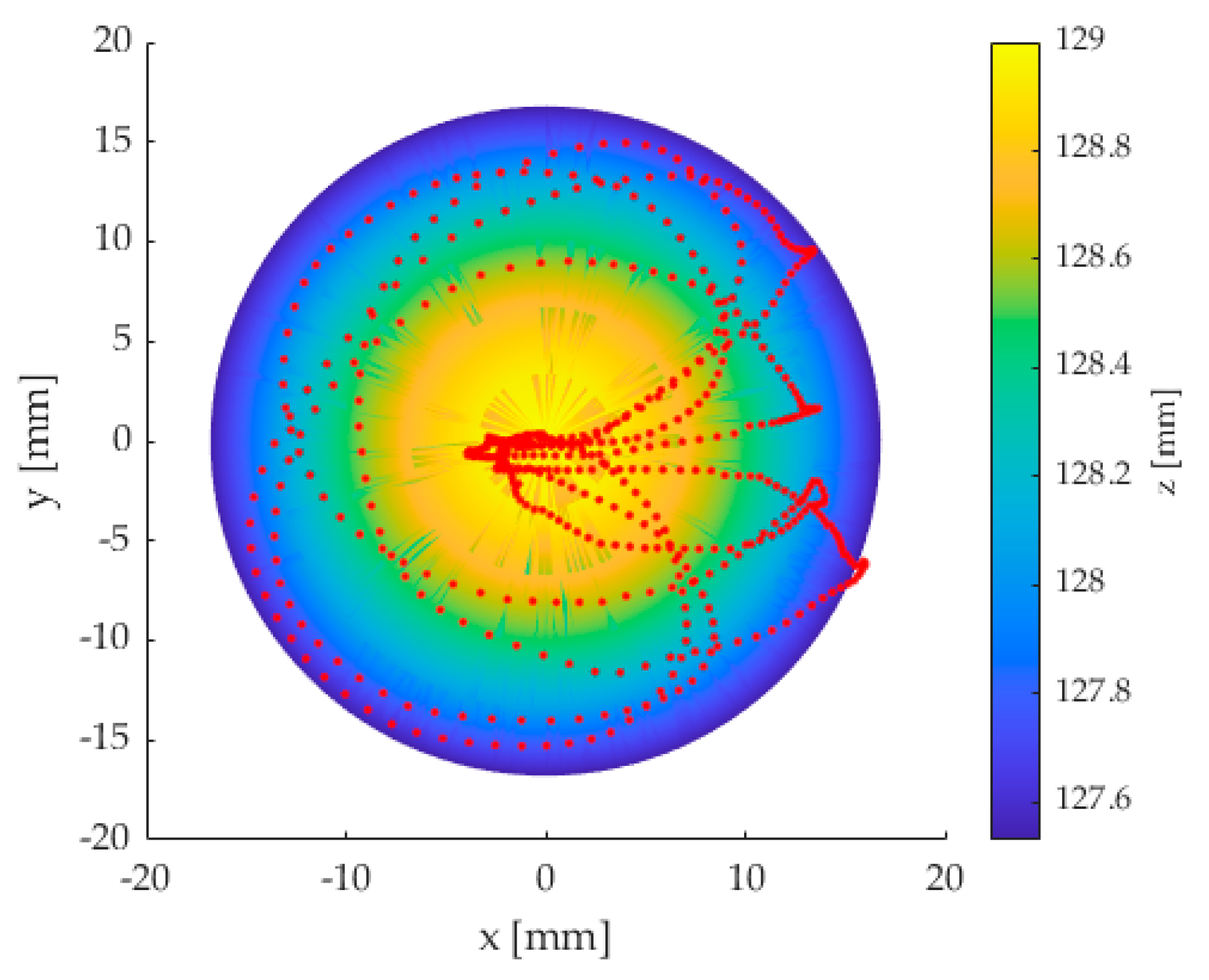
3.1. Workspace of the Proposed Torso Mechanism

Whereas the original motion planning was based on a regression between calibration points, the new analytical kinematic model enables a full characterization of the reachable workspace of the robot by defining all the reachable points of the mechanism. By using the forward kinematics in Equation (3), the reachable workspace of the mechanism was evaluated, given the size and motion parameters of the torso prototype in Figure 2, which are reported in Table 2. Once defined the motion limits on angle and direction of bending, as per Table 2, and by assuming a negligible compression of the backbone, the minimum and maximum tendon lengths were computed through Equation (4). The reachable workspace was defined as the geometrical locus of all the points that can be reached by the upper endpoint of the backbone’s centreline, and it was computed in MATLAB R2021a as plotted in Figure 5. As expected, for a negligible compression, the operational workspace shape resembles a convex surface.

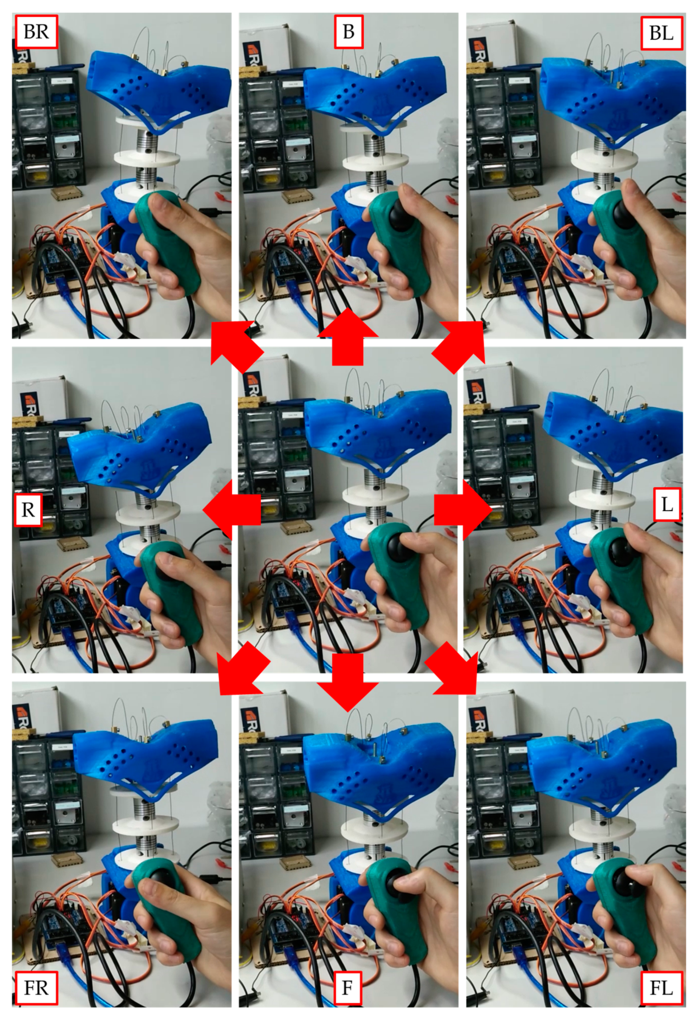
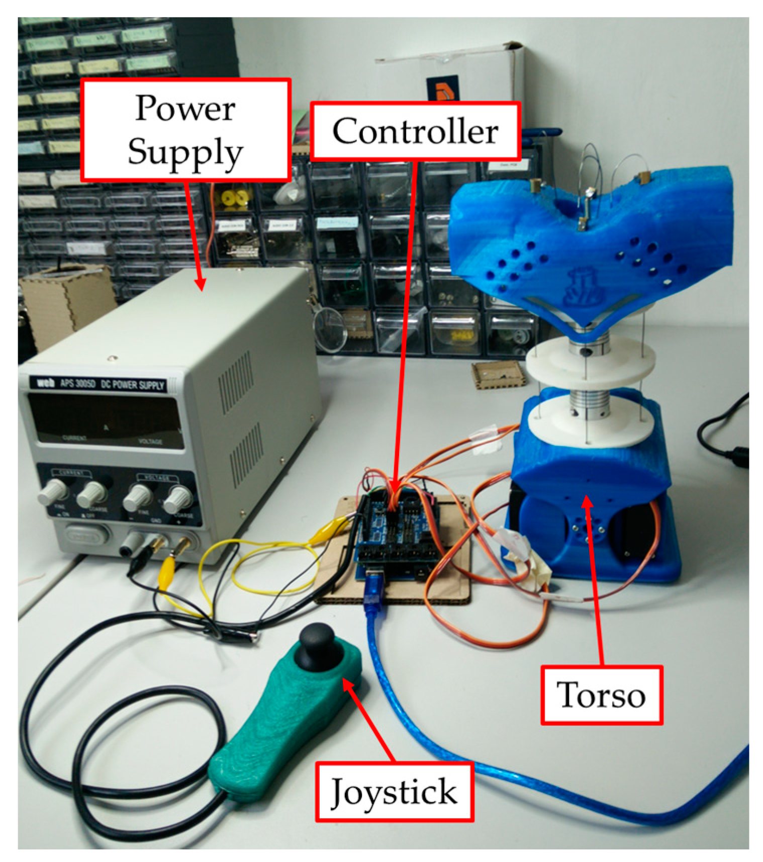
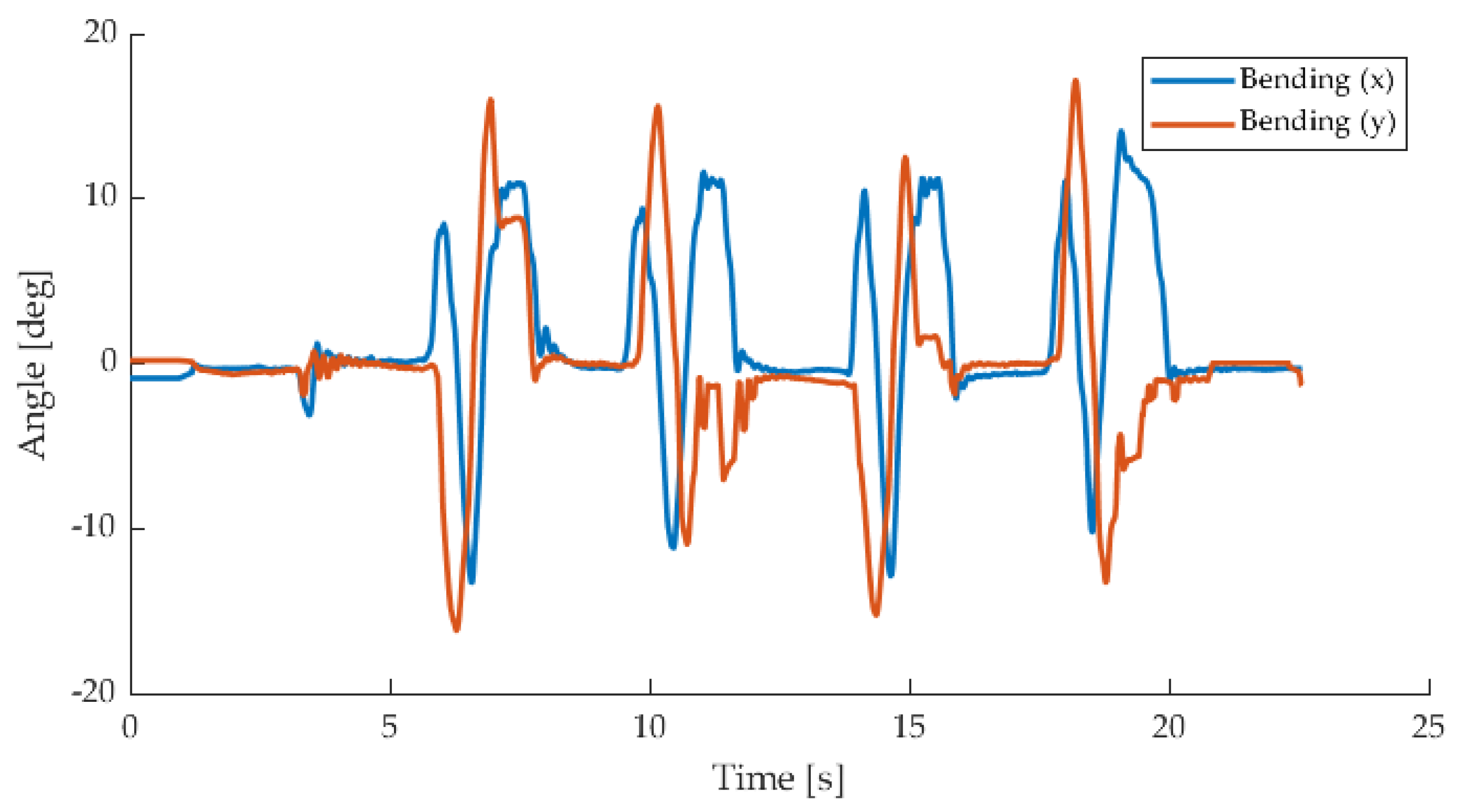
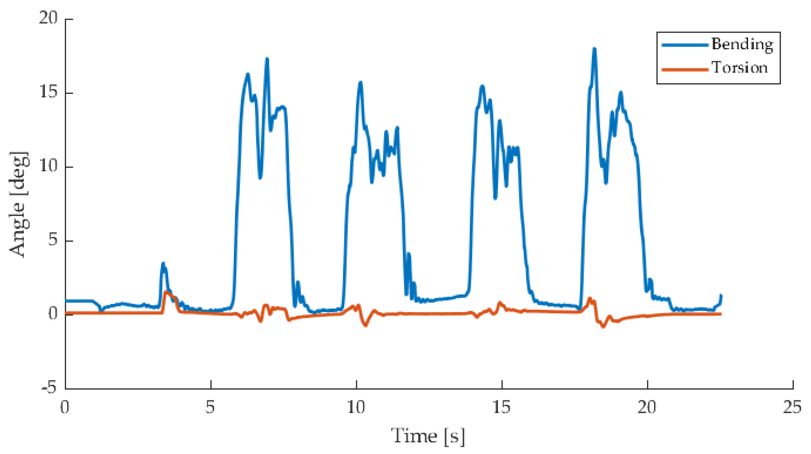
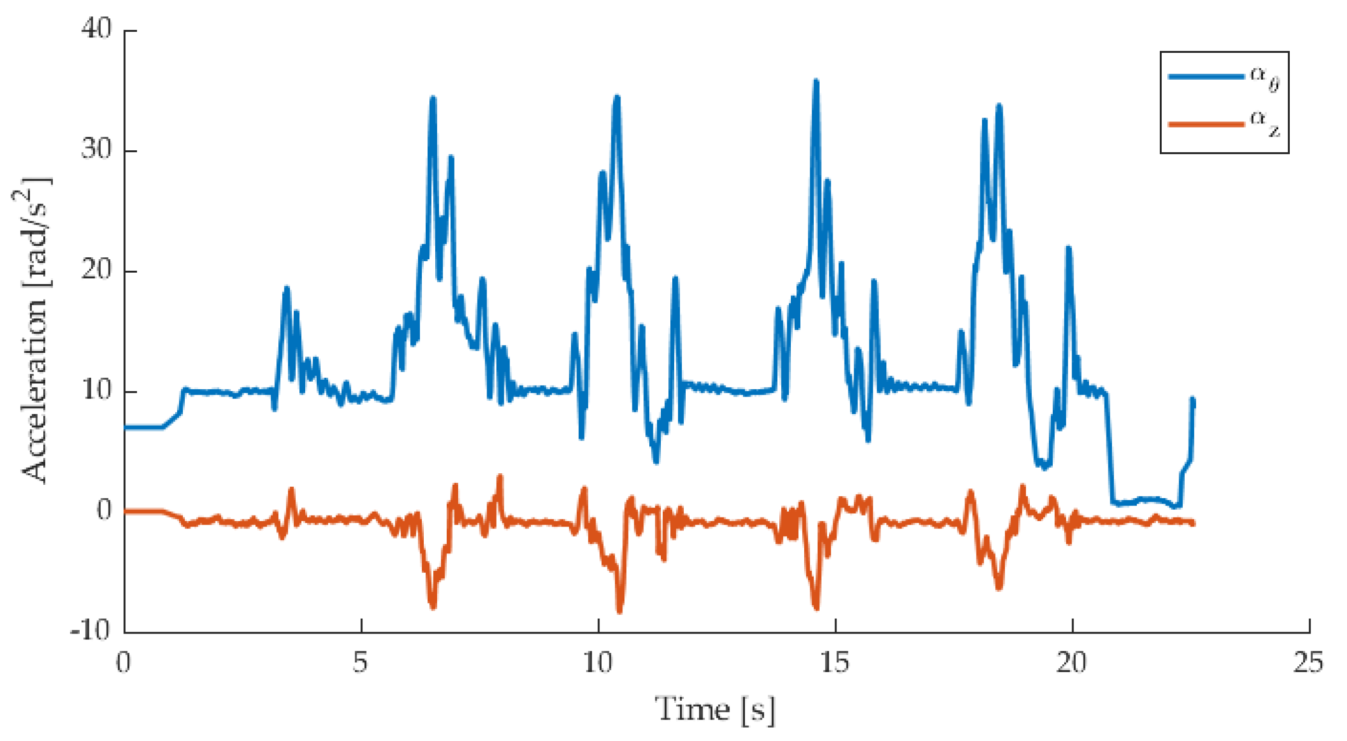
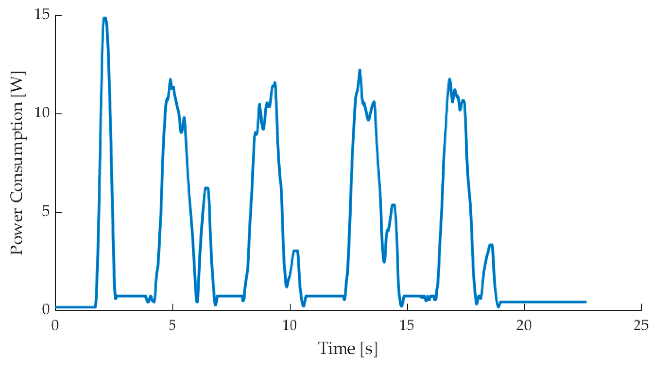
3.2. Experimental Validation

To validate the proposed kinematic model, the workspace result was compared to the reachable workspace of the prototype as per Figure 6, which was evaluated in the configuration space of the robot by measuring the orientation of the upper torso. The experimental setup is illustrated in Figure 7 with its main components, which include the torso prototype with an embedded IMU on the upper torso on the last Functional Spinal Unit (FSU) to extract the orientation data, an Arduino microcontroller with the kinematic model, a power supply, and a joystick (spring-loaded to the centre) to teleoperate the system. All the motors are embedded in the waist of the robot not to hinder spine motion. While a wired control was used in this experimental validation, wireless communication can enable autonomous navigation with the humanoid robot. The motion of the torso was mapped to the joystick motion according to the proposed kinematic model, with the direction of the joystick controlling the direction of bending φ and the position of the joystick linearly mapped to the bending angle θ . The extreme positions of this mapping are illustrated in Figure 6 with the corresponding upper torso pose.
In the reported experiment, the robot was driven from a central position (straight backbone) to a point on the outer border of its workspace and then was moved around the entire border once before going back to the central position (see Figure 6). This motion was repeated four times, and the motion data of the upper torso were reported in Figure 8 and Figure 9 as acquired by the IMU. Figure 8 illustrates the acquired motion as bending around the x- and y-axes of the torso mechanism, whereas Figure 9 reports the overall bending angle and axial torsion of the torso. The proposed torso mechanism can reach and move around the limits on its workspace, as illustrated in Figure 10, which shows the acquired IMU data points during a manually operated motion around the reachable workspace that was computed with the new analytical model. The experiments also show a negligible backbone elongation and torsion in absence of any external wrench, as motion is here obtained by tendon action only. The proposed model achieves a smooth motion, with acceleration values always below 36 rad/s2, as reported in Figure 11. The power consumption is also fairly low, with a maximum value below 15 W, as reported in Figure 12. The experimental results are summarised in Table 3.

4. Discussion

In this paper, a kinematic model was proposed for a four-DoF tendon-driven compliant torso mechanism for humanoid robots. The proposed model is presented with a closed-form analytical formulation and it is used to compute the workspace of the mechanism under examination. The results are validated on a prototype, which is operated with a joystick on which the proposed model is mapped. The main findings of this paper can be summarised as:
  • Mobility analysis: The mobility of a four-DoF tendon-driven compliant torso mechanism for humanoid robots is analysed to identify its main modes of motion. The degrees of mobility of the robot are further classified as active degrees of freedom, which can be controlled by the action of one or more actuators, and passive degrees of freedom, which depend on the intrinsic stiffness of the system only.
  • Kinematic modelling: The proposed constant curvature kinematic model, which is usually used for continuum robots, is used to describe the main bending mode of motion ( θ ,   φ ) of the spine of the torso. The conventional constant curvature kinematic model is characterised for the analysed system, and an expanded model is here proposed to include backbone elongation and torsion φ .
  • Stiffness modelling: A linearised stiffness model is introduced to create an efficient framework with lumped parameters to relate the deformation of the backbone to the wrench acting on the upper torso of the mechanism. This model also outlines how the axial torsion of the backbone cannot be controlled by the actuation tendons, as it can only be caused by external wrenches.
  • Workspace analysis: The behaviour of the torso mechanism is characterised by evaluating its motion limit as a reachable workspace, bending and direction angles, and tendon displacement.
  • Joystick mapping: A joystick mapping of the main motion parameters of the proposed kinematic model is proposed, with direction and angle of bending linearly mapped to joystick orientation and magnitude respectively.
  • Experimental validation: The workspace computed with the proposed model is confirmed by experiments with the prototype, whose motion is acquired by an onboard inertial measurement unit.
The main advantages of the proposed model, which replaces a previous approximated model calibrated on experimental data, can be identified as higher accuracy and efficiency and a quick response thanks to the closed-form analytical formulation. Furthermore, this model can be also used to evaluate the operating performance of the robot over the reachable workspace and to ensure that the tendon-driven architecture operates within its wrench-closure workspace.
Future works will focus on refining the current model by introducing a dynamic and stiffness model of the system, which will be validated with the addition of load cells on the tendons; by defining the performance of the torso through numerical indices that can be used to optimise motion planning; by analysing the compliant behaviour of the backbone with Finite Element analysis simulations in order to evaluate the error introduced by the lumped parameter model that is proposed in this manuscript; and finally by integrating this model with the kinematics of the whole humanoid, in order to implement a dynamic control of the system.

Author Contributions

Conceptualization, M.R., M.C., and D.C.; methodology, M.R.; software, M.R. and D.C.; validation, D.C.; formal analysis, M.R. and M.C.; investigation, M.R.; resources, M.C. and D.C.; data curation, M.R.; writing—original draft preparation, M.R.; writing—review and editing, M.R., M.C., and D.C.; visualization, M.R. and D.C.; supervision, M.C. and D.C.; project administration, M.C. and D.C.; funding acquisition, D.C. All authors have read and agreed to the published version of the manuscript.

Funding

This work was funded by a grant from Ministero della Salute (Ricerca Corrente 2021).

Institutional Review Board Statement

Not applicable.

Informed Consent Statement

Not applicable.

Data Availability Statement

Not applicable.

Conflicts of Interest

The authors declare no conflict of interest.

References

  1. Fitzpatrick, P.; Harada, K.; Kemp, C.C.; Matsumoto, Y.; Yokoi, K.; Yoshida, E. Humanoids. In Springer Handbook of Robotics; Springer: Cham, Switzerland, 2016; pp. 1789–1818. [Google Scholar]
  2. Gulletta, G.; Erlhagen, W.; Bicho, E. Human-like arm motion generation: A Review. Robotics 2020, 9, 102. [Google Scholar] [CrossRef]
  3. Sakagami, Y.; Watanabe, R.; Aoyama, C.; Matsunaga, S.; Higaki, N.; Fujimura, K. The intelligent ASIMO: System overview and integration. In Proceedings of the IEEE/RSJ International Conference on Intelligent Robots and Systems, Lausanne, Switzerland, 30 September–4 October 2002; IEEE: Piscataway, NJ, USA, 2002; Volume 3, pp. 2478–2483. [Google Scholar]
  4. Ogura, Y.; Aikawa, H.; Shimomura, K.; Kondo, H.; Morishima, A.; Lim, H.O.; Takanishi, A. Development of a new humanoid robot WABIAN-2. In Proceedings of the 2006 IEEE International Conference on Robotics and Automation, 2006. ICRA 2006, Orlando, FL, USA, 15–19 May 2006; IEEE: Piscataway, NJ, USA, 2006; pp. 76–81. [Google Scholar]
  5. Gouaillier, D.; Hugel, V.; Blazevic, P.; Kilner, C.; Monceaux, J.; Lafourcade, P.; Maisonnier, B. Mechatronic design of NAO humanoid. In Proceedings of the 2009 IEEE International Conference on Robotics and Automation, Kobe, Japan, 12–17 May 2009; IEEE: Piscataway, NJ, USA, 2009; pp. 769–774. [Google Scholar]
  6. Pandey, A.K.; Gelin, R. A mass-produced sociable humanoid robot: Pepper: The first machine of its kind. IEEE Robot. Autom. Mag. 2018, 25, 40–48. [Google Scholar] [CrossRef]
  7. Simonidis, C.; Stelzner, G.N.; Seemann, W. A kinematic study of human torso motion. In Proceedings of the International Design Engineering Technical Conferences and Computers and Information in Engineering Conference, Las Vegas, NV, USA, 4–7 September 2007; Volume 48094, pp. 773–780. [Google Scholar]
  8. Kljuno, E.; Williams, R.L. Humanoid walking robot: Modeling, inverse dynamics, and gain scheduling control. J. Robot. 2010, 2010, 278597. [Google Scholar] [CrossRef] [Green Version]
  9. Knudson, D. Fundamentals of Biomechanics; Springer Science & Business Media: Berlin, Germany, 2007. [Google Scholar]
  10. Li, Q.; Yu, Z.; Chen, X.; Meng, F.; Meng, L.; Huang, Q. Dynamic Torso Posture Compliance Control for Standing Balance of Position-Controlled Humanoid Robots. In Proceedings of the 2020 5th International Conference on Advanced Robotics and Mechatronics (ICARM), Shenzhen, China, 18–21 December 2020; IEEE: Piscataway, NJ, USA, 2020; pp. 529–534. [Google Scholar]
  11. Kaneko, K.; Kaminaga, H.; Sakaguchi, T.; Kajita, S.; Morisawa, M.; Kumagai, I.; Kanehiro, F. Humanoid robot HRP-5P: An electrically actuated humanoid robot with high-power and wide-range joints. IEEE Robot. Autom. Lett. 2019, 4, 1431–1438. [Google Scholar] [CrossRef]
  12. Yao, P.; Li, T.; Luo, M.; Zhang, Q.; Tan, Z. Mechanism design of a humanoid robotic torso based on bionic optimization. Int. J. Hum. Robot. 2017, 14, 1750010. [Google Scholar] [CrossRef]
  13. Cao, B.; Sun, K.; Jin, M.; Huang, C.; Zhang, Y.; Liu, H. Design and development of a two-DOF torso for humanoid robot. In Proceedings of the 2016 IEEE International Conference on Advanced Intelligent Mechatronics (AIM), Banff, AB, Canada, 12–15 July 2016; IEEE: Piscataway, NJ, USA, 2016; pp. 46–51. [Google Scholar]
  14. Fiorio, L.; Scalzo, A.; Natale, L.; Metta, G.; Parmiggiani, A. A parallel kinematic mechanism for the torso of a humanoid robot: Design, construction and validation. In Proceedings of the 2017 IEEE/RSJ International Conference on Intelligent Robots and Systems (IROS), Vancouver, BC, Canada, 24–28 September 2017; IEEE: Piscataway, NJ, USA, 2017; pp. 681–688. [Google Scholar]
  15. Cafolla, D.; Ceccarelli, M. Design and simulation of a cable-driven vertebra-based humanoid torso. Int. J. Hum. Robot. 2016, 13, 1650015. [Google Scholar] [CrossRef]
  16. Cafolla, D.; Ceccarelli, M. An experimental validation of a novel humanoid torso. Robot. Auton. Syst. 2017, 91, 299–313. [Google Scholar] [CrossRef]
  17. Russo, M.; Cafolla, D.; Ceccarelli, M. Design and experiments of a novel humanoid robot with parallel architectures. Robotics 2018, 7, 79. [Google Scholar] [CrossRef] [Green Version]
  18. Ceccarelli, M.; Cafolla, D.; Russo, M.; Carbone, G. LARMBot Humanoid Design Towards a Prototype. Moj Int. Jnl Appl. Bionics Biomech. 2017, 1, 00008. [Google Scholar]
  19. Cafolla, D.; Marco, C. Design and simulation of humanoid Spine. Mech. Mach. Sci. 2015, 24, 585–593. [Google Scholar]
  20. Cafolla, D.; Ceccarelli, M. Design and FEM analysis of a novel humanoid torso. Mech. Mach. Sci. 2015, 25, 477–488. [Google Scholar]
  21. Li, C.; Gu, X.; Ren, H. A cable-driven flexible robotic grasper with lego-like modular and reconfigurable joints. IEEE/ASME Trans. Mechatron. 2017, 22, 2757–2767. [Google Scholar] [CrossRef]
  22. Russo, M.; Ceccarelli, M. Analysis of a Wearable Robotic System for Ankle Rehabilitation. Machines 2020, 8, 48. [Google Scholar] [CrossRef]
  23. Amanov, E.; Nguyen, T.D.; Burgner-Kahrs, J. Tendon-driven continuum robots with extensible sections—A model-based evaluation of path-following motions. Int. J. Robot. Res. 2019. [Google Scholar] [CrossRef]
  24. Russo, M.; Raimondi, L.; Dong, X.; Axinte, D.; Kell, J. Task-oriented optimal dimensional synthesis of robotic manipulators with limited mobility. Robot. Comput. Integr. Manuf. 2021, 69, 102096. [Google Scholar] [CrossRef]
  25. Webster, R.J., III; Jones, B.A. Design and kinematic modeling of constant curvature continuum robots: A review. Int. J. Robot. Res. 2010, 29, 1661–1683. [Google Scholar] [CrossRef]
  26. Gonthina, P.S.; Kapadia, A.D.; Godage, I.S.; Walker, I.D. Modeling variable curvature parallel continuum robots using euler curves. In Proceedings of the 2019 International Conference on Robotics and Automation (ICRA), Montreal, QC, Canada, 20–24 May 2019; IEEE: Piscataway, NJ, USA, 2019; pp. 1679–1685. [Google Scholar]
  27. Mahl, T.; Hildebrandt, A.; Sawodny, O. A variable curvature continuum kinematics for kinematic control of the bionic handling assistant. IEEE Trans. Robot. 2014, 30, 935–949. [Google Scholar] [CrossRef]
  28. Garriga-Casanovas, A.; Rodriguez y Baena, F. Kinematics of continuum robots with constant curvature bending and extension capabilities. J. Mech. Robot. 2019, 11, 011010. [Google Scholar] [CrossRef] [Green Version]
  29. Russo, M.; Ceccarelli, M.; Takeda, Y. Force transmission and constraint analysis of a 3-SPR parallel manipulator. Proc. Inst. Mech. Eng. Part C J. Mech. Eng. Sci. 2018, 232, 4399–4409. [Google Scholar] [CrossRef]
  30. Cafolla, D.; Ceccarelli, M. Characteristics and Performance of CAUTO (CAssino hUmanoid TOrso) Prototype. Inventions 2017, 2, 17. [Google Scholar] [CrossRef]
Figure 1. The LARMbot humanoid robot [17,18]: (a) Architecture and mobility; (b) A prototype.
Applsci 11 02607 g001
Figure 2. A prototype of the LARMbot’s torso mechanism with its main components [15,16].
Applsci 11 02607 g002
Figure 3. A kinematic scheme of the LARMbot’s torso mechanism: (a) Main geometrical and motion parameters of the compliant backbone; (b) Cross-section view of a vertebra with actuation tendon routing geometry; (c) Side representation of the entire system in a straight configuration with tendons routing points on the lower and upper torso.
Applsci 11 02607 g003
Figure 4. A free-body diagram of the upper torso without any external wrench. The reactions of the backbone are represented by M z , F z , and M θ , whereas F 1 , F 2 , F 3 , and F 4 are the tensions in the actuation tendons.
Applsci 11 02607 g004
Figure 5. Workspace of the LARMbot’s torso mechanism evaluated through the proposed PCCK model with elongation and torsion.
Applsci 11 02607 g005
Figure 6. Motion control of the LARMbot’s torso mechanism through a joystick, with motion mapping to angle of direction and bending angle. F: forward; FL: forward-left; L: left; BL: backward-left; B: backward; BR: backward-right; R: right; FR: forward-right.
Applsci 11 02607 g006
Figure 7. Experimental setup for the validation of the proposed kinematic model, including the torso mechanism, an Arduino microcontroller, a joystick for teleoperation, and a power supply.
Applsci 11 02607 g007
Figure 8. Raw orientation data acquired by the IMU on the upper torso expressed as bending around the x- and y-axes of the upper torso of the robot in Figure 6.
Applsci 11 02607 g008
Figure 9. Orientation data acquired by the IMU on the upper torso and mapped as torso bending angle θ and axial torsion φ .
Applsci 11 02607 g009
Figure 10. Top view of the acquired teleoperated torso motion and comparison with the computed workspace in Figure 5.
Applsci 11 02607 g010
Figure 11. Acceleration data acquired by the IMU on the upper torso mapped as angular acceleration around the instantaneous bending axis α θ and around the backbone axis α z .
Applsci 11 02607 g011
Figure 12. Power consumption acquired with a current sensor during the torso motion reported in Figure 8 and Figure 9.
Applsci 11 02607 g012
Table 1. Technical specifications of the LARMbot’s torso mechanism (CAUTO) [15,16].
Width [mm]Depth [mm]Height [mm]
200150300
Mass [kg]Backbone MobilityActuators
1.2004 Degrees of Freedom 14 Servomotors 2
1 Bending angle, direction of bending, axial torsion, axial elongation. 2 The tendon-driven architecture means that four motors can actively control three degrees of freedom.
Table 2. Size and motion parameters of the torso mechanism prototype in Figure 2.
Backbone Length Bending Angle θ Bending Direction φ
129.0 mm[0; 15] deg[0; 360] deg
Backbone compression Tendon length l i Tendon radius r
0.0 mm[120.0; 138.0] mm34.0 mm
Table 3. Experimental results.
Maximum Angular ValueMaximum Acceleration
Backbone bending θ = 17.95 deg α θ = 35.75 rad/s2
Backbone torsion φ = 1.54 deg α z = 8.32 rad/s2
Publisher’s Note: MDPI stays neutral with regard to jurisdictional claims in published maps and institutional affiliations.

