Article

Experimental and Numerical Study of Thermal Performance of an Innovative Waste Heat Recovery System

1
Faculty of Civil Engineering and Building Services, “Gheorghe Asachi” Technical University of Iasi, 700050 Iasi, Romania
2
IUSTI Laboratory, Aix-Marseille University, 13453 Marseille, France
*
Authors to whom correspondence should be addressed.
Appl. Sci. 2021, 11(23), 11542; https://doi.org/10.3390/app112311542
Submission received: 16 November 2021 / Revised: 27 November 2021 / Accepted: 1 December 2021 / Published: 6 December 2021
(This article belongs to the Special Issue Urban Sustainability and Resilience of the Built Environments)

Abstract

:
One of the biggest challenges the world is facing these days is to reduce the greenhouse gases emissions in order to prevent the global warming. Since a significant quantity of CO2 emissions is the result of the energy producing process required in industry or buildings, the waste heat recovery is an important aspect in the fight for preserving the planet. In this study, an innovative waste heat recovery system which can recover waste heat energy from cooling liquids used in industry or in different processes, was designed and subjected to experimental investigations. The equipment uses heat pipes to capture thermal energy from the residual fluids transiting the evaporator zone and transfer it to the cold water transiting the condenser zone. The efficiency of the heat exchanger was tested in 9 scenarios, by varying the temperature of the primary agent to 60, 65 and 70 °C and the volume flow rate of the secondary agent to 1, 2 and 3 L/min. The temperature of the secondary agent and the volume flow rate of the primary agent were kept constant at 10 °C, respectively 24 L/min. The results were later validated through numerical simulations, and confirmed that the equipment can easily recover waste thermal energy from used water with low and medium temperatures at very low costs compared to the traditional heat exchangers. The results were promising, revealing an efficiency of the equipment up to 76.7%.

1. Introduction

According to a study [1] made in 2019, the building sector is responsible for about 16% of the wasted heat energy. The waste heat energy with a value lower than 100 °C is considered low-temperature, the one with a temperature between 100 °C and 300 °C is medium-temperature, while the waste heat energy with a temperature higher than 300 °C is considered high-temperature. The highest losses of thermal energy are in the low-temperature sector, with a percentage of 64%. Waste heat recovery can have a significant impact on the energy efficiency of buildings by reducing the heat losses. There are various heat recovery technologies such as waste heat boilers [2], economisers [3], plate heat exchangers [4], heat pipe heat exchangers [5] and others, which all have the purpose to capture the waste thermal energy and convert it to active thermal or electrical energy [6].
The waste heat utilization is very diverse and it has been developed in the last few years. There are numerous works in the literature which concentrate on waste heat recovery using heat pipes. The original contribution of this work consists in designing and testing a compact equipment which can recover thermal energy from low-temperature residual fluids at low costs of production and maintenance using termosyphons. Since the gravitational heat pipes is a passive technology and do not require any moving parts, the costs of recovering thermal energy are reduced.
Asl et al. [7] made a theoretical and practical research on three different approaches to implement a geothermal waste heat recovery system which is supplying the necessary heat to the pools of a fish farm. The results showed that when the most efficient method is used, the minimum costs of establishing a heat recovery system decrease by 60.65%. Liang et al. [8] tried to improve the performance of the exhaust heat recovery from diesel engines by using a regenerative super-critical carbon dioxide Brayton cycle/organic Rankine cycle dual loop system. The results showed an improvement of the engine power output by 6.78%, which can be translated as a lower fuel consumption.
A team of researchers made a numerical study on a waste heat recovery steam generator for hydrogen production. The research was aimed to improve the heat transfer mechanism of semi-coke and steam. The 7.5 kg/h proved to be the best steam flow for an efficient heat recovery rate [9].
Scientist have studied the possibility of introducing heat pipes in process of heat recovery for an improved efficiency of these type of systems. A heat pipe consists of a sealed enclosure, made from a heat conductive material and a working fluid. When heat is applied to the evaporator zone, the working fluid turns into vapor and transfers the heat to the condenser zone at a high rate. The vapors turn into liquid droplets and returns to the evaporator zone either with the help of gravity or through wick (Figure 1). Because the pressure inside the heat pipe is very low, the working fluid evaporates at a lower temperature than usual, making the heat pipe a super-conductor even at low temperatures.
The most important benefit of heat pipes is that it is a passive way to recover thermal energy, which makes the process of waste heat recovery cheaper. Another advantage is their high conductance potential compared to common heat recovery technologies. Since each heat pipe functions individually, a heat pipe heat exchanger can operate properly even if one of them fails. Also, the fluids involved in the heat recovery process will not be mixed or contaminated in case of a heat pipe failure.
The most common use of heat pipes is for solar applications. Studies have tried to improve the efficiency of heat pipes in solar collectors by testing different working fluids [10], by using thermal oil [11] or by adding fins to the condenser region of the heat pipes [12]. The optimum fill ratio is also an important factor on the efficiency heat pipes [13]. A study by Yang [14] investigated a novel high-temperature two-phase closed flat heat pipe which uses sodium as a working fluid. Burlacu [15] performed numerical simulations on a system which proposes the introduction of heat pipes in glazed facades.
There are also many applications of heat pipes in the waste heat recovery field. Mahajan proved in his study [16] that by using oscillating heat pipes in waste heat recovery ventilation can save more than 2500 $ annually in cities with continental climatic conditions. Jouhara [17] presented a nuclear seawater desalination system based on heat pipe technology, while Tian [18] recovered waste heat from exhaust gases using a heat recovery gravity heat pipe heat exchanger. A study [19] made in 2018 presented a heat pipe heat exchanger with concentric tube heat pipes and acetone as working fluid used for low-temperature heat sources. Heat pipes were also used in designing a dual heat recovery system which recovers waste heat from residual fluids and produces simultaneously hot water and warm air [20]. A study [21] presented in 2019 analyzed the possibility of combining heat pipes with phase change materials in order to recover and store thermal energy more efficiently.
Delpech et al. [22] designed a heat pipe heat exchanger which has the purpose to recover the heat resulted during the cooling of a ceramic kiln. The recovered heat is used to heat up an air stream which will be used in the ceramic process to dry the ceramic parts. The heat pipe-based heat exchanger was able to recover more than 863 MWh of thermal energy and also reduce the fuel consumption of the ceramic process by 110,600 Sm3/year which is the equivalent of 164 tons/year of CO2. In another experiment, Delpech et al. [23] improved the process of heat recovery in the ceramics industry using a radiative heat pipe system which was able to recover heat through radiation and natural convection in an enclosed kiln. Depending on the heater’s temperature, the heat pipe can recover between 400 W and 3100 W.
Jouhara et al. [24] developed a heat recovery system based on a flat heat pipe heat exchanger which was tested in the laboratory and on an industrial plant. The equipment is meant to recover the radiative heat resulted during the cooling process of steel wires. The rate of heat recovery for the laboratory tests was 5 kW, while for tests made on the industrial plant the efficiency was doubled.
This research presents a numerical and experimental study of thermal performance on an innovative prototype of a waste heat recovery system designed and manufactured in the laboratory of the Faculty of Civil Engineering and Building Services of Technical University “Gheorghe Asachi” of Iasi, Romania. The device has a modular design, with two main components, the evaporator and the condenser, and is using heat pipes for improving the heat transfer inside the device. The novelty and the originality brought by this research consists in using the axial flow for the primary and the secondary agent around the heat pipes for increasing the heat exchange surface and consequently the energy performance of the waste heat recovery system. Thus, the equipment can easily recover waste thermal energy from used water with low and medium temperatures at very low costs compared to the traditional heat exchangers, which represents an important goal in the research domain of modern heat exchangers. The recovered energy can be used for preheating or heating water for domestic use or for other heating systems without any additional pumping system or any other forms or additional energy resulting a high energy efficient innovative waste heat recovery system. The results of the experimental investigations were validated through numerical simulations.

2. Materials and Methods

2.1. The Design of the Heat Pipe Heat Recovery System

The heat pipe heat recovery system (HPHE) is used to recover waste heat from used water through the heat pipes and use it for heating up a volume of cold water. The equipment has a circular design, with a diameter of 0.25 m and a height of 1.04 m. The material used for building the evaporator and condenser is steel, while the heat pipes are made of cooper. The heat pipes do not have a wick structure inside, they use gravity to return the condensate and they were specially designed for this equipment. The working fluid of the heat pipes is water and the pressure inside was set close to 4300 Pa, in order for the fluid to evaporate when it will reach a temperature of 30 °C, thus making the heat pipe efficient in low-temperature applications.
Inside the HPHE there are 14 heat pipes inserted vertically through the separation flange, which are transporting the heat recovered from the primary agent inside the evaporator to the secondary agent inside the condenser. Inside the condenser there are three steel rings and two steel discs for a better circulation of the secondary agent and a more uniform heating. The condenser, the evaporator and the separation flange are connected using 9 screws and nuts. The constructive details of the components can be viewed in Table 1. The design of the heat pipe heat recovery system was made using the Autodesk Inventor 2018 software. The model and its components can be seen in Figure 2.

2.2. Experimental Setup

Using the 3D model we built a prototype of the equipment and tested it in the laboratory. Also, a stand has been designed and manufactured as shown in Figure 3. The primary agent was hot water heated by an electric heater with a power of 8 kW and the temperature could be adjusted as needed.
The electric heater is connected to the heat recovery system through flexible stainless-steel pipes with a diameter of 16 mm. The pipe circuit was equipped with a faucet for filling/emptying the evaporator and the primary circuit, and a probe sheath for measuring the temperature of the primary agent. The circuit of the secondary agent is connected directly to the water supply network of the laboratory. Two probe sheaths were installed at the inlet and outlet of the condenser to track temperature variations and also an ELTERM CF 55 thermal energy meter which is tracking the volume flow rate and the temperature of the secondary agent. The thermal sensors inserted in the probe sheaths are connected to an LT BTM-4208SD electronic thermometer which has a precision of ±0.4%.
The equipment was tested with different temperatures of the primary agent and different volume flow rates, using the parameters presented in Table 2. For each test, the valve on the circuit of the secondary agent was opened at maximum to keep the secondary agent as cold as possible during the process of heating up the secondary agent. When the temperature of the secondary agent reached the value required for testing, the valve was set for the proper volume flow rate required for the test.

2.3. Numerical Simulations

The 3D model designed in the Autodesk Inventor environment was imported in Autodesk CFD Simulation software. The geometry was discretized in a network consisting 500,000 nodes and the first simulation was run. In order to find a proper mesh that presents the most accurate results, the number of meshing elements was increased gradually until the differences between two consecutive simulations were insignificant.
Another criteria for choosing the proper number of mesh elements was the computational power. The higher the number of elements, the longer time required for calculation. According to these criteria, the optimum mesh network was chosen the one consisting in 1.2 M nodes.
The boundary conditions can be observed in Table 2. There were carried out 9 simulations with various parameters.
The temperature of the secondary agent, TCo,1, and the volume flow rate of the primary agent, q2, were kept constant at 10 °C respectively 24 L/min, while the temperature of the primary agent, TEv,1, was varied to 60 °C, 65 °C and 70 °C and the volume flow rate of the secondary agent, q1, was varied to 1 L/min, 2 L/min and 3 L/min.
The simulations were run in steady state and the results obtained are defining the moment when the temperature at the outlet of the secondary agent reaches a quasi-constant temperature.
The governing equations for fluid flow and heat transfer are the Navier-Stokes or momentum equations and the First Law of Thermodynamics or energy equation. These equations are used by the Autodesk CFD Simulation software to calculate and describe the heat transfer process.

3. Results

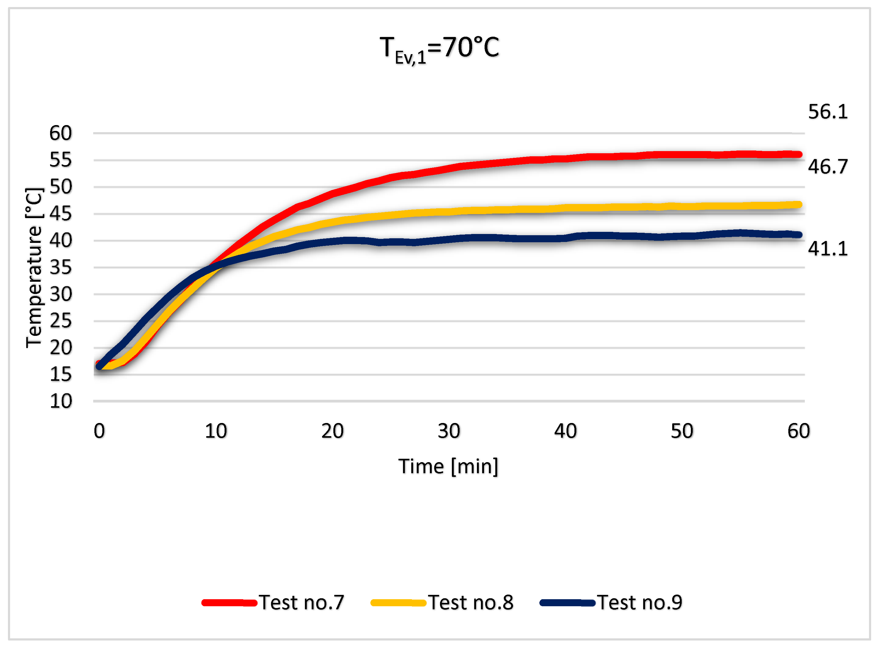
3.1. Experimental Results

The temperature of the primary agent was kept constant for one hour. Since the temperature of the secondary agents is rising very slowly after about 50 min, and the variations are small, we considered that after 1 h of constant temperature in the condenser the temperature of the evaporator reaches a quasi-constant state.
The sensors CH1, CH2, and CH3 are responsible for tracking the temperature variation in time. CH1 is placed at the inlet of the condenser, CH2 at the outlet of the condenser and CH3 at the inlet of the evaporator. The electronic thermometer was set to record the temperature every 60 s.
The temperature recorded after 60 min for the test no. 1 was 40.7 °C, for the test no. 2 the results showed 35.7 °C, while for the test no. 3 the temperature was 32.1 °C. As we can observe in Figure 4, the most significant temperature variation takes place in the first 10 min. After this period of time, the rising of temperature is slower.
To visualize the external temperature of the heat recovery system, we took some photos with a FLIR thermal vision camera during test no. 1. In Figure 5 we can observe that most of the heat recovered is first absorbed by the water in the middle of the condenser during the first 15 min of the test, but after that, the temperature tends to become uniform inside the condenser.
For the next 3 tests we used a temperature of 65 °C at the inlet of the evaporator and the sensors revealed a temperature of 47.4 °C for test no. 4, 41.8 °C for test no. 5 and 36.3 °C for test no. 6. In the first 10 min, the volume flow rate of the secondary agent does not have a significant impact on the heat recovery rate. After about 20 min, the temperature rise in the condenser is slow, with about 0.1 °C/min for all of the three cases (Figure 6).
The tests were repeated for the same volume flow rates but this time with the temperature of the primary agent of 70 °C. As we can observe in Figure 7, the temperature of the secondary agent after 60 min was 56.1 °C for case no. 7, 46.7 °C for case no. 8 and 41.1 °C for case no. 9. Again, the amount of heat recovered in the first 10 min does not depend on the volume flow rate of the secondary agent. After 10 min, the ΔT between the inlet and the outlet of the condenser is about 18.5 °C for all three cases (Figure 7).

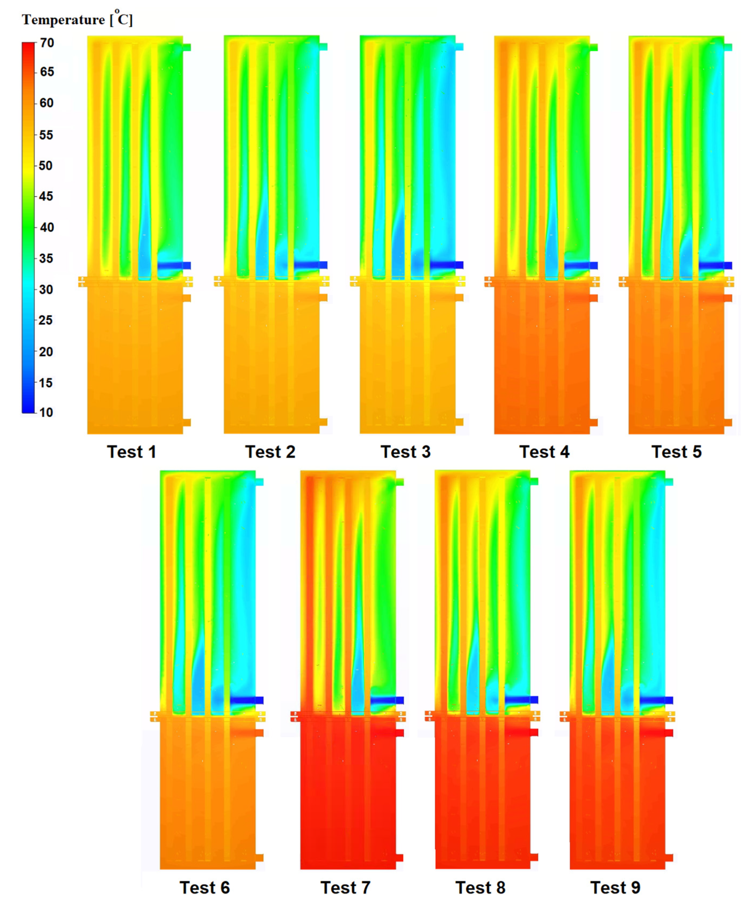
3.2. Numerical Simulations Results

For the numerical simulations we used as boundary conditions the same parameters as in the experimental setup, presented in Table 2. The temperature of the primary agent to 60, 65 and 70 °C and the volume flow rate of the secondary agent to 1, 2 and 3 L/min. The temperature of the secondary agent and the volume flow rate of the primary agent were kept constant at 10 °C, respectively 24 L/min.
The mesh consisted in 1.2 million of elements and the simulations were run in steady state. By using the surface refinement tool, the mesh was refined at the interfaces between fluids and solids and on the smaller areas of the equipment, for an improved capture of the heat transfer. The results were centralized in a graph in Figure 8.
The experimental results were validated by the numerical simulations. The temperatures obtained in the numerical simulations were slightly higher than the experimental ones, with values between 2 and 5 °C. This can be explained due to heat losses from the experimental test, which the simulation does not take into account.
The simulation environment is also a useful tool for observing the heat process that happens inside the heat recovery system. Figure 9 presents a 2D section through the middle of the equipment for the 9 tests.
From Figure 9 it can be concluded that the heat transfer inside the condenser can be further improved by creating a path for the secondary agent.

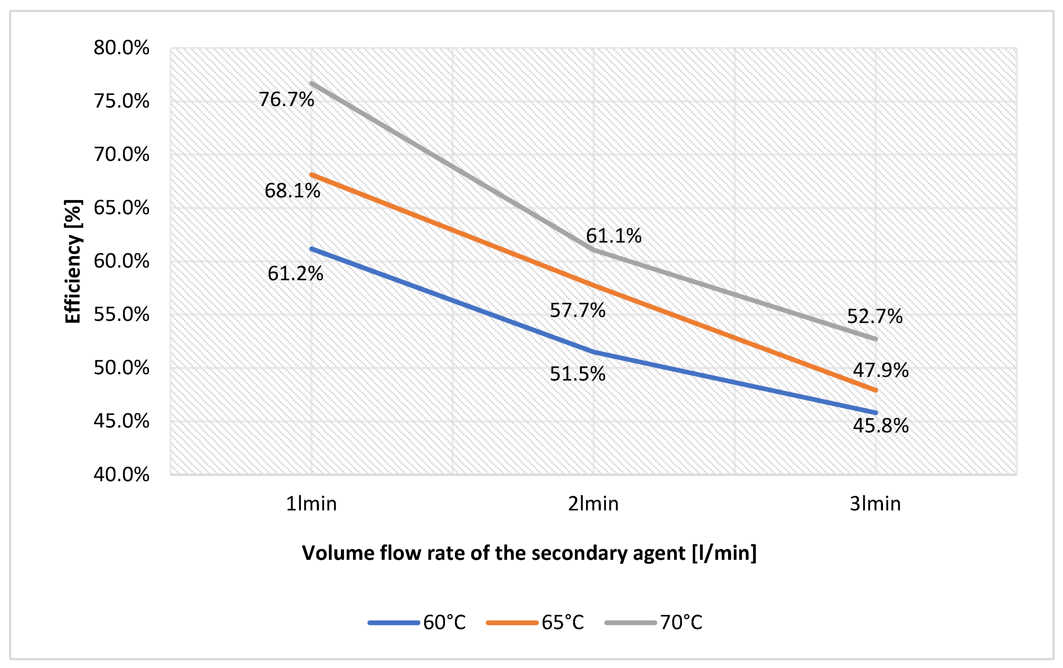
3.3. The Efficiency of the Equipment

The efficiency of the heat pipe heat exchanger can be evaluated as its thermal effectiveness which is the ratio between the heat transfer rate, Q, and the maximum heat transfer rate of the equipment, Qmax. The equation can be expressed as:
ε = Q Q max
Q = C Ev ( T Ev ,   1 T Ev ,   2 ) = C Co ( T Co ,   2 T Co ,   1 )
By using the Equation (2) we can determine the heat transfer rate for the heat recovery system. CEv and CCo represent the heat capacity rate for the evaporator and the condenser section and can be determined as the product of the mass flow rate and the specific heat capacity for the referred section.
C Ev = Ev × c p , Ev
Q max = C min ( T Ev ,   1 T Co ,   1 )
Q max = Co × C p , Co ( T Ev ,   1 T Co ,   1 )
For the expression of Qmax we have used Cmin instead of Cmax because Qmax represents the maximum heat transfer rate for the heat exchanger but for this case, we have a limiting factor represented by the minimum heat capacity rate between the two fluids.
By applying the Equations (2) and (5), the Equation (1) can be written as follows:
ε = Q Q max = Ev × C p , Ev × ( T Ev , 1 T Ev , 2 ) Co × C p , Co × ( T Ev , 1 T Co , 1 )
The highest efficiency of the heat recovery system was in test no. 7, when the temperature of the secondary agent after 1 h was 56.1 °C compared to 70 °C, the temperature of the primary agent, which means an efficiency of 76.7% (Figure 10).

4. Conclusions

A heat pipe heat recovery system was designed, manufactured and tested. The thermal performance of the equipment was investigated through experimental tests and confirmed by numerical simulations. Also, an efficiency calculation was made based on the experimental data obtained.
Compared with classic heat recovery system, this equipment produces hot water at lower costs, given the fact that the heat pipes are a passive technology and do not require any moving parts. The results showed that it needs about 10–15 min until it is able to produce hot water at almost constant temperature. The efficiency of the heat pipes is increasing directly proportional to the temperature of the primary agent. An efficiency of 76.7% was obtained with a temperature of 70 °C of the primary heat source, but the results showed that this percentage can be further improved.
It can be concluded that the heat pipe heat recovery system can be a feasible solution for recovering thermal energy from used waters. As further researches, the equipment can be tested at even higher volume flow rates for the secondary agents and the number of heat pipes could be varied. Also, industrial tests may be carried out to check the efficiency of the heat pipe heat recovery system in factories.

Author Contributions

Conceptualization, R.S.V., A.B. and M.C.B.; methodology, A.B.; software, R.S.V.; validation, R.S.V., A.B., C.A. and M.V.; formal analysis, R.S.V., C.A. and M.B.; investigation, R.S.V., A.B., C.A. and M.B.; resources, M.V.; data curation, R.S.V. and M.B.; writing—original draft preparation, R.S.V. and M.B.; writing—review and editing, A.B., C.A., M.V. and M.C.B.; visualization, R.S.V. and A.B.; supervision, A.B., C.A. and M.C.B.; project administration, A.B., C.A., M.V. and M.C.B.; funding acquisition, M.V. and M.C.B. All authors have read and agreed to the published version of the manuscript.

Funding

This work was supported by a publications grant of the TUIASI, project number GI/P28/2021.

Institutional Review Board Statement

Not applicable.

Informed Consent Statement

Not applicable.

Data Availability Statement

Not applicable.

Acknowledgments

This work was supported by a publications grant of the TUIASI, project number GI/P28/2021.

Conflicts of Interest

The authors declare no conflict of interest.

Nomenclatures

HPHEHeat pipe heat recovery system
TEv,1Temperature of the primary agent at the inlet of the evaporator [°C]
TCo,1Temperature of the secondary agent at the inlet of the condenser [°C]
q1Volume flow rate of the primary agent [L/min]
q2Volume flow rate of the secondary agent [L/min]
CH1Thermal sensor at the inlet of the evaporator
CH2Thermal sensor at the inlet of the condenser
CH3Thermal sensor at the outlet of the condenser
TTime [min]
λThermal conductivity [W/m*K]
εThermal effectiveness of the HPHE [%]
QHeat transfer rate of the HPHE [W]
QmaxMaximum theoretical heat transfer rate of the HPHE [W]
CevHeat capacity rate of the evaporator [W/K]
TEv,2Temperature of the primary agent at the outlet of the evaporator [°C]
CcoHeat capacity rate of the condenser [W/K]
TCo,2Temperature of the secondary agent at the outlet of the condenser [°C]
EvMass flow rate of the primary agent [kg/m3]
CoMass flow rate of the secondary agent [kg/m3]
Cp,EvSpecific heat of the primary agent [J/kg*K]
Cp,CoSpecific heat of the secondary agent [J/kg*K]
CminMinimum heat capacity rate between the two fluids [W/K]

References

  1. Firth, A.; Zhang, B.; Yang, A. Quantification of global waste heat and its environmental effects. Appl. Energy 2019, 235, 1314–1334. [Google Scholar] [CrossRef]
  2. Men, Y.; Liu, X.; Zhang, T. A review of boiler waste heat recovery technologies in the medium-low temperature range. Energy 2021, 237, 121560. [Google Scholar] [CrossRef]
  3. Termtech. Reducing Energy Costs with Economisers. Available online: https://thermtech.co.uk/reducing-energy-costs-with-economisers/ (accessed on 25 November 2021).
  4. Arsenyeva, O.; Klemes, J.J.; Kapustenko, P.; Fedorenko, O.; Kusakov, S.; Kobylnik, D. Plate heat exchanger design for the utilisation of waste heat from exhaust gases of drying process. Energy 2021, 233, 121186. [Google Scholar] [CrossRef]
  5. Xie, C.Y.; Tao, H.Z.; Li, W.; Cheng, J.J. Numerical simulation and experimental investigation of heat pipe heat exchanger applied in residual heat removal system. Ann. Nucl. Energy 2019, 133, 568–579. [Google Scholar] [CrossRef]
  6. Jouhara, H.; Khordehgah, N.; Almahmoud, S.; Delpech, B. Waste heat recovery technologies and applications. Therm. Sci. Eng. Prog. 2018, 6, 268–289. [Google Scholar] [CrossRef]
  7. Asl, S.G.; Gilandeh-Abbaspour, Y. Theoretical and practical analysis of waste heat recovery system in off-season rainbow trout production. Aquac. Eng. 2019, 85, 65–73. [Google Scholar] [CrossRef]
  8. Liang, Y.; Bian, X.; Qian, W.; Pan, M.; Ban, Z.; Yu, Z. Theoretical analysis of a regenerative supercritical carbon dioxide Brayton cycle/organic Rankine cycle dual loop for waste heat recovery of a diesel/natural gas dual-fuel engine. Energy Convers. Manag. 2019, 197, 111845. [Google Scholar] [CrossRef]
  9. Gao, H.; Liu, Y.; Song, X.; Zheng, B.; Sun, P.; Lu, M.; Ma, Y.; Gao, Z. Numerical study of heat transfer characteristics of semi-coke and steam in waste heat recovery steam generator for hydrogen production. Int. J. Hydrogen Energy 2019, 44, 25160–25168. [Google Scholar] [CrossRef]
  10. Jayanthi, N.; Suresh Kumar, R.; Karunakaran, G.; Venkatesh, M. Experimental investigation on the thermal performance of heat pipe solar collector (HPSC). Mater. Today Proc. 2020, 26, 3569–3575. [Google Scholar] [CrossRef]
  11. Abd-Elhady, M.S.; Nasreldin, M.A.; El-Sheikh, M.N. Improving the performance of evacuated tube heat pipe collectors using oil and foamed metals. Ain Shams Eng. J. 2018, 9, 2683–2689. [Google Scholar] [CrossRef]
  12. Brahim, T.; Dhaou, M.H.; Jemni, A. Theoretical and experimental investigation of plate screen mesh heat pipe solar collector. Energy Convers. Manag. 2014, 87, 428–438. [Google Scholar] [CrossRef]
  13. Dehaj, M.S.; Mohiabadi, M.Z. Experimental investigation of heat pipe solar collector using MgO nanofluids. Sol. Energy Mater. Sol. Cells 2019, 191, 91–99. [Google Scholar] [CrossRef]
  14. Yang, L.; Ling, X.; Peng, H.; Duan, L.; Chen, X. Starting characteristics of a novel high temperature flat heat pipe receiver in solar power tower plant based of “Flat-front” Startup model. Energy 2019, 183, 936–945. [Google Scholar] [CrossRef]
  15. Burlacu, A.; Lăzărescu, C.D.; Ciocan, V.; Verdes, M.; Balan, M.C.; Serbanoiu, A.A. CFD Heat transfer analysis for heat pipes integration into buildings with glazed facades. Procedia Eng. 2017, 181, 658–665. [Google Scholar] [CrossRef]
  16. Mahajan, G.; Thompson, S.M.; Cho, H. Energy and cost savings potential of oscillating heat pipes for waste heat recovery ventilation. Energy Rep. 2017, 3, 46–53. [Google Scholar] [CrossRef]
  17. Jouhara, H.; Anastasov, V.; Khamis, I. Potential of heat pipe technology in nuclear seawater desalination. Desalination 2019, 249, 1055–1061. [Google Scholar] [CrossRef] [Green Version]
  18. Tian, E.; He, Y.L.; Tao, W.Q. Research on a new type waste heat recovery gravity heat pipe exchanger. Appl. Energy 2017, 188, 586–594. [Google Scholar] [CrossRef]
  19. Xiaoxing, H.; Yaxiong, W. Experimental investigation of the thermal performance of a novel concentric tube heat pipe heat exchanger. Int. J. Heat Mass Transf. 2018, 127, 1338–1342. [Google Scholar]
  20. Vizitiu, R.S.; Sosoi, G.; Burlacu, A.; Turcanu, F.E. CFD Analysis of a Dual Heat Recovery System. E3S Web Conf. 2019, 85, 02007. [Google Scholar] [CrossRef] [Green Version]
  21. Vizitiu, R.S.; Burlacu, A.; Isopescu, D.N.; Verdes, M.; Sosoi, G.; Lazarescu, C.D. CFD analysis of an innovative heat recovery system. Procedia Manuf. 2019, 32, 488–495. [Google Scholar] [CrossRef]
  22. Delpech, B.; Milani, M.; Montorsi, L.; Boscardin, D.; Chauhan, A.; Almahmoud, S.; Axcell, B.; Jouhara, H. Energy efficiency enhancement and waste heat recovery in industrial processes by means of the heat pipe technology: Case of the ceramic industry. Energy 2018, 158, 656–665. [Google Scholar] [CrossRef]
  23. Delpech, B.; Axcell, B.; Jouhara, H. Experimental investigation of a radiative heat pipe for waste heat recovery in a ceramics kiln. Energy 2019, 170, 636–651. [Google Scholar] [CrossRef]
  24. Jouhara, H.; Almahmoud, S.; Chauhan, A.; Delpech, B.; Bianchi, G.; Tassou, S.A.; Llera, R.; Lago, F.; Arribas, J.J. Experimental and theoretical investigation of a flat heat pipe heat exchanger for waste heat recovery in the steel industry. Energy 2017, 141, 1928–1939. [Google Scholar] [CrossRef]
Figure 1. The operating principle of heat pipes.
Applsci 11 11542 g001
Figure 2. The 3D design of the HPHE.
Applsci 11 11542 g002
Figure 3. The experimental stand: 1—Electric heater, 2—Condenser, 3—Evaporator, 4—Faucet for filling/emptying the primary circuit, 5—Flowmeter, 6—Faucet for controlling the volume flow rate, 7—Water supply faucet, 8—LT BTM-420SD electronic thermometer, 9—Elterm CF 55 flow temperature meter.
Applsci 11 11542 g003
Figure 4. The variation of temperature at the outlet of the condenser for tests no. 1, 2, 3.
Applsci 11 11542 g004
Figure 5. Photos with FLIR thermal camera during test no. 1.
Applsci 11 11542 g005
Figure 6. The variation of temperature at the outlet of the condenser for tests no. 4, 5, 6.
Applsci 11 11542 g006
Figure 7. The variation of temperature at the outlet of the condenser for tests no. 7, 8, 9.
Applsci 11 11542 g007
Figure 8. Results of the numerical simulations.
Applsci 11 11542 g008
Figure 9. 2D section plane.
Applsci 11 11542 g009
Figure 10. The efficiency of the heat recovery system.
Applsci 11 11542 g010
Table 1. Constructive details of the components.
ComponentHeight [m]Diameter [m]
Evaporator0.3950.25
Condenser0.640.25
Separation flange0.0050.246
Discs0.0050.15
Rings0.0050.246
Heat pipes10.015
Table 2. Testing parameters.
TEv,1 [°C]TCo,1 [°C]q1 [L/min]q2 [L/min]
Test no. 16010124
Test no. 26010224
Test no. 36010324
Test no. 46510124
Test no. 56510224
Test no. 66510324
Test no. 77010124
Test no. 87010224
Test no. 97010324
Publisher’s Note: MDPI stays neutral with regard to jurisdictional claims in published maps and institutional affiliations.

