1. Introduction
Nowadays, an ever-expanding human population coupled with a growth in anthropogenic activities and general better standards of living have led to a significant surge in overall energy consumption [
1,
2]. Presently, most of the energy generation comes from fossil fuel sources;
Figure 1 and
Figure 2 show how the widespread use of coal, oil, and natural gas since the beginning of the 19th century has led to the continued emission of greenhouse gases—such as carbon dioxide, methane, and nitrous oxide—causing a gradual increase in the concentration of these gases in the Earth’s atmosphere and contributing to environmental degradation and climate change (it should be noted that the most recent measurement has already peaked at 419 ppm, in May of this year) [
3,
4].
As is well known, the presence of these gases in the atmosphere traps heat radiating from the Earth toward space, effectively warming it.
Figure 3 shows how there is mounting evidence that this global warming is man-made, namely, by observing the rise of world temperatures, the warming of the oceans, shrinking ice sheets, glacial retreats, decreased snow cover, the declining of the Arctic Sea ice, a broad sea level rise, widespread ocean acidification, and more extreme weather events in general [
5,
6,
7].
Figure 1.
CO
atmospheric concentration: long-term overview. Based on data retrieved from [
8].
Figure 1.
CO
atmospheric concentration: long-term overview. Based on data retrieved from [
8].
Figure 2.
Relationship between fossil fuel consumption and CO
concentration in the atmosphere. Based on data retrieved from [
8].
Figure 2.
Relationship between fossil fuel consumption and CO
concentration in the atmosphere. Based on data retrieved from [
8].
Figure 3.
Relationship between CO
concentration in the atmosphere and global temperature anomaly. Based on data retrieved from [
9].
Figure 3.
Relationship between CO
concentration in the atmosphere and global temperature anomaly. Based on data retrieved from [
9].
Furthermore, fossil fuels are naturally a finite resource; so, using them is inherently limiting the use of such energy sources by future generations. While these factors are enough to motivate a total replacement to alternative sources of energy, it turns out that we are actually increasing the use of these conventional fuels, whose impacts are already rapidly approaching tipping-points that will bring disastrous consequences for humanity [
10,
11,
12].
Fighting climate change might be the greatest challenge of this generation; it all boils down to halting the temperature rise, which in turn means decreasing the atmospheric concentration of greenhouse gases, which, again, in turn means finding solutions to replace fossil fuels as our primary energy source; to reverse the on-going global warming, we urgently need to decarbonize the world economy—hence, the development of renewable energy sources has become essential. While such renewable sources like solar and wind can provide environmentally friendly alternatives to fossil fuels, their intermittent nature brings the need of an energy storage medium that allows for the continual provision of energy; as there is no one-size-fits-all solution, we need a multi-faceted approach to accomplish that. For instance, instead of using common batteries, these sources could grant the energy needed to produce hydrogen from water, which can then be stored as a means to generate electrical and mechanical energy, as well as heat—thus ensuring the continuous production of emissions-free energy, which is necessary to fulfill modern society’s consumption requirements [
13,
14]. The push for environmentally friendly energy solutions has renewed the interest to accelerate the development of hydrogen production methods. Currently, around 96% of global hydrogen production comes from non-renewable fossil fuels [
15,
16]. However, besides releasing harmful greenhouse gases to the atmosphere, these methods can only produce low-purity hydrogen [
17,
18,
19].
This article focused on studying green hydrogen production methods, namely, through the analysis of different types of water electrolysis technologies currently being developed and used in modern industry—including their characteristics and modes of operation, their advantages and disadvantages, and their similarities and differences. It does so integrated on hydrogen’s value chain, therefore adding to this growing body of research. However, an extensive review of the state of the art in general hydrogen production methods is given, including all the current main methods of producing hydrogen—either by renewable or non-renewable sources: hydrocarbon reforming, thermochemical biomass processes, biological biomass processes, and water splitting. The research regarding these several production technologies is deepened, referring to the respective detailed challenges and future trends on related published work; this review addresses not only current and commercial technologies but also future technologies presently in the research phase (but which are expected to be of interest for the coming years). This analysis is one of this article’s most valuable assets, as, to the best knowledge of the authors, no such review is available in the literature.
The remainder of the article is arranged as follows:
Section 2 gives a general description of hydrogen’s value chain, addressing the main end-use strategic configurations and the leading prevailing forms of storage.
Section 3 then delivers an overview on hydrogen production technologies, starting with a background explanation of some important concepts and then moving to the in-depth study of electrolysis. A literature review takes place in
Section 4, and the article ends with some conclusions in
Section 5.
2. Hydrogen Value Chain
Some now argue that a true decarbonized economy cannot even exist without hydrogen. The European Commission is particularly determined to make Europe deliver on its ambitious climate promise to achieve carbon neutrality by 2050; in its main document related to the introduction of green hydrogen technology, it aims to give a boost to clean production, since this immensely versatile energy vector could find many possible applications in all major sectors of modern society—from industry to buildings to transportation [
20].
Figure 4 shows a generic scheme of hydrogen’s value chain, hinting that to frame the implementation of this strategy, it is important to first define the configurations considered to be priorities in the hydrogen value chain—from production to final consumption. This comprises, in practice, three phases:
Production. The first stage of the hydrogen value chain consists in its production, with different pathways, processes, and associated technologies already identified. Depending on the required scale, large-scale (centralized) production is distinguished from small-scale (decentralized) production—ideally, close to the place of consumption;
Storage and Distribution. The second stage starts with storage and ends with delivery for final use. This stage includes processes that generally break down into sub-processes; a sub-process can be, for instance, underground gas storage, liquefaction, compression, storage and distribution in gas networks, road and maritime transport, or refueling. Naturally, all these have their own risk and safety concerns associated with the operation at very low temperatures and/or very high pressures, requiring tanks with higher thicknesses to guarantee insulation levels; this topic will be addressed with more detail in
Section 2.2.2.
Likely combinations of hydrogen fueling processes could be:
- –
Road distribution in the form of liquefied/compressed gas, ending with a liquid-to-liquid refueling process, liquid-to-gaseous cryogenic storage systems, or gas-to-gas at various scales;
- –
Distribution by ships in the form of liquefied hydrogen, including delivery for end-use in oil pipelines and road transport;
- –
Distribution of gaseous hydrogen through pipeline systems;
- –
Blending of hydrogen with natural gas in the current natural gas infrastructure.
End-use. In the third stage, the hydrogen value chain is addressed to the main end-use applications in the mobility/transport and industrial sectors. In residential and industrial stationary applications, mixtures of hydrogen and natural gas can be applied to generate heat and electricity.
An utmost important matter on this last phase is with regards to the strategic configuration of the hydrogen value chain, i.e., how hydrogen going to be used as an energy vector.
2.1. End-Use on Hydrogen Value Chain
Generally speaking, the current characteristics of any generic energy system allows five main end-use configurations: power-to-gas (P2G), power-to-mobility (P2M), power-to-industry (P2I), power-to-synfuel (P2FUEL), and power-to-power (P2P) [
21].
2.1.1. Power-to-Gas Configuration
Figure 5 shows a general arrangement of a typical P2G value chain, alluding to be mainly directed towards the decarbonization of the current natural gas system.
This approach involves mixing (blending) hydrogen with natural gas, aiming for the gas networks to transport more energy from renewable sources than from fossil origin in the medium to long term [
22]. Considering that both the technical characteristics of the end-use equipment (furnaces, turbines, boilers…) and those of the gas network itself impose limitations on the percentage composition of hydrogen in the mixture, there is also the option—or the need—to build dedicated hydrogen networks.
2.1.2. Power-to-Mobility Configuration
P2M aims at mobility and transport, considering the technical design and installation of refilling station networks resorting to: geo-optimization tools that help find the best locations to make accurate mapping of those places, cost-minimization analysis of fuel cells on board of vehicles—with a particular focus on light vehicles (taxis, company fleets, and shared mobility), heavy vehicles (goods and passengers), rail (non-electrified trains), ships, and even airplanes [
23,
24]—and profitability analysis of on-site hydrogen production. The scheme on
Figure 6 displays an overview of a typical P2M value chain.
Currently, there are already several companies and promoters with P2M projects in progress, namely, involving the modeling, optimization, and performance simulations of energy consumption related to the hydrogen refilling stations for light and heavy vehicles; these are mainly associated with logistics centers, industries, transport fleets, and cruise ships—clearly showing the research interest and dynamic already generated in this particular field of hydrogen’s value chain [
25,
26].
2.1.3. Power-to-Industry Configuration
P2I refers to hydrogen usage in modern industry; presently, it is an essential chemical agent for the production of ammonia, methanol, various polymers, and many other compounds and materials in oil refining and also as a process byproduct in some sub-sectors of the inorganic chemical industry (many more applications can be identified with a wide-level range of technological maturity) [
27].
Looking at
Figure 7, which depicts a generic scheme of P2I, hydrogen has primarily the potential to replace natural gas as a heat source in industry, in processes where electrification is not possible or is economically inefficient—such as sectors that use high temperatures (e.g., steel and cement)—which may require the adaptation or replacement of equipment but do not need highly pure hydrogen [
28,
29].
2.1.4. Power-to-Fuel Configuration
Synthetic fuels are currently produced by steam reforming of fossil hydrocarbons (mainly methane) and by coal or biomass gasification. Other technologies include coal liquefaction, namely, through direct processes like co-processing and dry hydrogenation, where coal is directly converted to liquid synfuel avoiding the initial conversion to syngas.
Figure 8 presents a general overview of what a P2FUEL value chain looks like, indicating how different renewable technologies can enable the production of these fuels, leading to the perspective that all crude oil products could at first be produced synthetically—resulting in true renewable fuels [
30]. P2FUEL thus states that, in conjunction with the electrification of the economy and previous value chains, this route could in principle lead to the total decarbonization of the energy sector [
31].
2.1.5. Power-to-Power Configuration
Finally, if its purpose is to participate in the electricity supply market, the production of electrical energy using properly adapted gas turbines or hydrogen fuel cell stations—which in itself is produced with electricity—may be, at first glance, an energy-inefficient option.
Nonetheless,
Figure 9 shows a possible design scheme of P2P, revealing how it may be interesting from a system’s services point of view, especially with regards to storage (in addition to batteries and dams with a pumping mode) and presents an option that strengthens the security of supply in a context of accelerated decarbonization of the electricity sector. For instance, when dealing with dry hydrological years, in which there is a lower availability of water resources, large amounts of stored hydrogen could be used to feed high-power fuel cells (or possibly even hydrogen turbines), in this way ensuring supply security [
32,
33].
2.2. Storage on Hydrogen Value Chain
A new question now arises about this stored hydrogen; current storage options consist mainly of compressed gas, cryogenically frozen or liquefied gas, and chemical storage (such as in metal hydrides and ammonia) [
34].
2.2.1. Storage by Compression
Although compressing hydrogen requires less energy than liquifying it, storing hydrogen in a compressed gaseous state requires substantially more storage space; that is disadvantageous. Even so, compressed hydrogen gas is presently the most commonly used storage technology. This system has many advantages, such as a simple operation (resulting in low costs), rapid (dis)charge cycles at a wide range of temperatures, and low energy requirements, as mentioned before [
34]. Nonetheless, due to the overall low density of hydrogen as a gas, the main obstacle of this kind of storage is possibly that it requires bulky systems (over two times the volume that of natural gas with the same energy output) [
35,
36,
37]. Hydrogen as a compressed gas is also more volatile than in all other storage options; leaks due to impact or compartment failure may result in a rapid discharge of a highly explosive gas. Moreover, these issues may include material weakening, which causes premature degradation of mechanical properties and results in cracking and loss of the storage cylinders’ rigidity [
38].
2.2.2. Storage by Liquefaction
The process of liquefying hydrogen requires large amounts of energy, since this gas has extremely low boiling and melting points (−252.9 °C and −259.2 °C, respectively). This results in a high energy consumption required for solid and liquid hydrogen storage options, needing up to 30% of its potential stored energy; additionally, the insulation requirements for such storage are not easy to obtain [
34], despite tanks of cryogenic hydrogen being much lighter than, say, tanks that can hold pressurized hydrogen.
Studies on the optimization process of large-scale hydrogen liquefaction have found that a wide range of lower-cost, highly efficient designs are heavily dependent on the plant’s capacity; selecting the optimal process also depends on other relevant conditions such as the plant’s location, utility costs, and customer needs [
39]. Moreover, case-study analysis of advanced liquefaction systems have shown how there is still room for improvement on what concerns overall efficiency challenges. These may include changes in the hydrogen’s feed temperature and the catalysts themselves; the total yield could further benefit from design adjustments that reduce environmental impact and waste production [
40].
2.2.3. Storage by Chemical Processes
Regarding chemical storage methods, metal hydride systems in particular store hydrogen in a solid-state—that happens when hydrogen molecularly bonds to the metal— resulting in a much safer and high-volume efficient tankage when compared to liquid or gas [
34,
38]; although this being still an emerging technology, it has already reached high levels of safety—proven to be non-reactive even to bullets [
41]. This presents as a major advantage over, say, battery storage, which nowadays still has associated risks with explosiveness. Current research on metal hydrides is focused on improving the adsorption properties and decreasing the cost of this system [
34,
38], with magnesium hydride appearing as a promising solution due to its favorable properties; however, this system requires relatively high ambient temperatures to (dis-)charge, which may pose a drawback to the transportation sector. Such drawbacks are currently being addressed through research on several different production techniques, as well as the study of catalyst inclusion to the systems [
34].
On the other hand, hydrogen can also be stored in ammonia. This compound is well known and used within the fuel industry, making it easily one highly valued hydrogen storage option. It has a relatively high hydrogen density and a high utilization flexibility—both in stationary and mobile applications. As ammonia’s capabilities ensure long-term stable storage and transportation, it can cope with the needs to store energy in time and in space (stationary and export/import energy, respectively) [
42]. When comparing these storage methods, liquid ammonia was found able to store volumes of hydrogen larger than, say, liquefied hydrogen itself. Besides, it can also be stored at normal pressure and temperature conditions (1 bar and 25 °C, respectively)—much lower than compressed hydrogen gas, for example. However, this very high density also means heavier storage and a special transportation demand. Moreover, the process of releasing hydrogen from ammonia downstream consumes great amounts of energy, requiring even more in the case where high-purity hydrogen is needed; this could arguably be the most challenging aspect of high-efficiency hydrogen storage in ammonia, particularly considering that both compressed and liquid hydrogen easily deliver pure hydrogen from design [
27]. Methanol could be seen as competitor of ammonia-based hydrogen storage, as it yields higher energy density; however, it has a lower hydrogen content by weight and volume [
43].
Table 1 offers a summary of the described so far, compiling the major advantages and disadvantages of the leading hydrogen storage technologies.
Nowadays, the most advanced technologies for storing hydrogen are cryogenically liquefied and compressed gas [
38]; but these methods may not be completely suitable for future widespread hydrogen applications, mainly due to leakage and safety concerns in their pressurized form and energy requirements in the case of liquefaction. Even so, as the push for environmentally friendly solutions is gaining traction, new technologies are constantly being researched and developed to overcome these issues [
38].
3. Hydrogen Production Technologies
Hydrogen has been produced, in one form or another, for a long time. Most of that time, and to this day, it has been produced through environmentally unsustainable methods; thus, one of the most important and urgent goals of the scientific community today is to decarbonize hydrogen production.
3.1. Background Concepts
Some of these processes are briefly described below; they are further discussed with more detail in
Section 4 below.
3.1.1. Steam Methane Reforming
This is a process in which methane is heated, with steam (usually also with a catalyst), to produce a mixture of carbon monoxide and hydrogen [
44]. Methane, coming from natural gas, reacts with steam under a pressure up to 25 bar, splitting into carbon monoxide (later removed) and hydrogen molecules—as shown in Equation (
1). Because this is an endothermic reaction, heat must be supplied to the process for it to occur:
3.1.2. Oil and Naphtha Reforming
Also known as catalytic reforming, this is a complex chemical process used to convert petroleum refinery naphthas (distilled from crude oil) into high-octane liquid reformates, which are stocks for gasoline [
45]. The process converts linear hydrocarbons into branched alkanes and cyclic naphthenes, which are then partially dehydrogenated to produce high-octane aromatic hydrocarbons—and also significant amounts of hydrogen gas, as a byproduct.
3.1.3. Coal Gasification
Coal is a chemically complex and highly variable substance, which can be converted into a variety of products. The gasification process of coal is one method to produce power, liquid fuels, chemicals, and hydrogen [
46].
Specifically, hydrogen is produced by first reacting coal with oxygen and steam—under high pressures and temperatures—to form synthesis gas (a mixture consisting primarily of carbon monoxide and hydrogen), like is shown in Equation (
2).
After removing impurities from the synthesis gas, the carbon monoxide present in the gas mixture reacts again with steam to produce additional hydrogen and carbon dioxide, following the reaction of Equation (
3).
Hydrogen is removed in a separation system, and the highly-concentrated carbon dioxide stream is subsequently captured and stored.
3.1.4. Biomass
Being a renewable organic resource, biomass usually includes forest and agriculture crop residues and animal and other organic solid waste [
47], and it can be used to produce hydrogen, along with other byproducts, by gasification. As seen below, in Equation (
4), this process converts organic carbonaceous materials into carbon mono-/dioxide and hydrogen, at high temperatures, without combustion and with a controlled amount of oxygen or steam intake.
Note: Actual biomass has a highly variable composition and complexity, with cellulose being one major component; the reaction above uses glucose as a substitute.
Carbon monoxide then reacts with water to form more carbon dioxide and more hydrogen via a water–gas shift reaction (Equation (
3)), and special membranes separate the hydrogen from this gas stream.
Pyrolysis is a particular type of biomass gasification technology that uses no oxygen. This is because, in general, biomass does not gasify as easily as coal, producing other hydrocarbon compounds in the gas mixture exiting the gasifier.
As a result, an extra step must typically be taken to reform these hydrocarbons to yield a clean syngas mixture of hydrogen, carbon monoxide, and carbon dioxide. Then, just as in the gasification process for hydrogen production, a shift reaction happens (with steam) that converts the carbon monoxide to carbon dioxide—hydrogen is produced and then separated and purified.
3.1.5. Biological Hydrogen Production
Photobiological processes use live microorganisms and sunlight to turn water—and sometimes organic matter—into hydrogen. In photolytic biological systems, microorganisms such as green microalgae or cyanobacteria use sunlight as a mechanism to split water into oxygen and hydrogen ions; these hydrogen ions are later combined through direct or indirect routes and released as hydrogen gas [
48]. Some photosynthetic microbes use sunlight as the driver to break down organic matter, releasing hydrogen; this mechanism is commonly known as “photofermentative hydrogen production,” and some of its major challenges include a very low production rate and a low solar-to-hydrogen efficiency—something researchers are currently looking at, expecting to make the microbes better at collecting and using energy, thus becoming more suited overall for hydrogen production.
3.1.6. Water Electrolysis
This method refers to the oldest method of producing hydrogen, dating back to the 19th century [
49]; it generally refers to a DC electrical power source connected to two electrodes, which are then placed in water. The flow of an electric current splits water molecules into its constituents, making hydrogen appear at the cathode side and oxygen appear at the anode side. The efficiency of electrolysis is increased through the addition of an electrolyte to the solution (such as a salt, an acid, or a base) and the use of electrocatalysts, which raise the reaction’s rate too.
The article now focuses on recent developments of this technology, discussing its efficiency, durability, cost, and overall challenges.
3.2. Water Electrolysis Technologies
While there are many different methods to produce hydrogen, currently the vast majority of the global hydrogen production comes from non-renewable fossil fuels—in particular, steam reforming of methane—mainly due to its low cost and high efficiency. However, these processes also tend to produce less-pure hydrogen, besides obviously releasing harmful greenhouse gasses to the atmosphere [
17].
So, today, new environmentally friendly energy strategies are sought to replace the current system, namely through water electrolysis; this method enables the production of eco-friendly, high-purity hydrogen, in addition to still releasing oxygen as a byproduct—as seen in Equation (
5).
However, water electrolysis is still not economically competitive due to high energy consumption costs and low hydrogen yield rates [
15]. In order to increase overall efficiency, many researchers have been looking to develop alternatives with low-cost electrocatalysts and less energy consumption.
Equation (
5) shows that, in electrolysis processes, water molecules are the reactant, which—under the influence of electricity and heat—dissociate into hydrogen and oxygen, in an oxidation–reduction process. This process can be then classified into three main types, based on its operating conditions, the electrolyte and electrolyzer used, and the ionic agent present (OH
−, H
+, O
2−): alkaline electrolysis (AEL), proton-exchange membrane electrolysis (PEMEL), and solid oxide electrolysis (SOEL), respectively.
3.2.1. Alkaline Water Electrolysis
Hydrogen production by alkaline water electrolysis was first introduced by Troostwijk and Diemann in 1789 [
50], so it is by now a well-established technology.
Figure 10 shows a generic depiction of an alkaline water electrolyzer.
This electrolyzer is characterized by having two electrodes operating in a liquid alkaline electrolyte solution, generally potassium or sodium hydroxide (KOH or NaOH, respectively); the electrodes are kept apart by a diaphragm, where the transport of the hydroxide ions (OH
−) occurs, from one electrode to the other [
51].
So, the process initiates at the cathode, the site of reduction, where two molecules of an alkaline water solution are reduced to one molecule of hydrogen (H
2), and two hydroxyl ions are produced (OH
−). The produced hydrogen emanates from the cathode surface to recombine in a gaseous form, while the hydroxyl ions transfer through the porous diaphragm to the anode, under the influence of the imposed electrical potential. Here a similar reaction occurs: two water molecules are oxidized, forming one diatomic oxygen (O
2) molecule and four hydrogen atoms. These half-reactions are shown below:
To obtain the overall cell equation, one just has to add both half-equations:
which is the same as Equation (
5).
Alkaline electrolysis normally operates at low temperatures, around 30–80 °C, and, as seen, uses an aqueous solution as the electrolyte [
52,
53]. The diaphragm is usually made of asbestos [
54] and electrodes made of nickel; this diaphragm in the middle of the cell is what separates the cathode side from the anode side, avoiding the mixing of the produced gases [
55]. This method does have some negative aspects, such as limited current densities, low operating pressure, and low energy efficiency, making this type of electrolyzer just suited to operate at almost constant power while connected to the grid; one of the highest-powered electrolyzers of this type, however, has shown to have a dynamic response fast enough to track the production of a renewable power plant [
56].
An investment cost analysis from the past 30 years [
57] revealed that capital expenditure (CAPEX) values for large alkaline electrolyzers can vary significantly over plant capacity, ranging from EUR 1250 /kW
el to around EUR 700/kW
el—depending on whether the plant is small (<1 MW) or large (>40 MW), respectively. The annual operational expenditures (OPEX) are generally around 7% for medium-sized plants, but, due to superior technical approaches and a higher lifespan, it is expected to decrease to 2% in 2030 [
57].
3.2.2. Proton-Exchange Membrane Electrolysis
The first PEMEL was idealized by Grubb in the early 1950s, having been later developed by General Electric Co. (Boston, MA, USA) in 1966 to overcome the drawbacks of AEL [
58,
59,
60].
Figure 11 displays a schematic illustration of a proton-exchange membrane water electrolyzer, showing how the working principle of this technology is very similar to that of PEM fuel cells—actually being the exact reverse—with solid polysulfated membranes used as an electrolyte (proton conductor), through which the ionic agents move during the process [
61,
62,
63].
Finally, the protons and electrons re-combine at the cathode side to produce hydrogen, as shown in the following half-reactions:
These proton-exchange membranes have many important characteristics, such as low gas permeability, high proton conductivity, small thickness, and the potential to operate at high pressures and ambient temperatures. In terms of sustainability and environmental impact, PEMEL is also found to be one of the most favorable methods for conversion of renewable energy to highly pure hydrogen; this is mainly due to other promising advantages like its compact design, high current density (meaning higher efficiencies), fast response, and small footprint [
63,
64,
65,
66]. Additionally, PEMEL plants are very simple, which is more attractive for industrial applications; these applications might include offshore wind parks [
67], grid-independent/grid-assisted solar hydrogen generation and grid-independent integrated solar hydrogen energy systems [
68].
Electrocatalysts used in this method are usually noble metals such as platinum or palladium for the cathode [
65,
69] and iridium/ruthenium oxide for the anode [
70,
71,
72,
73], which makes the whole process more expensive than, say, alkaline water electrolysis. Here water is accrued by being pumped on the anode side, where it is electrochemically split into oxygen, hydrogen protons, and single electrons; these protons then travel via the proton-exchange membrane to the cathode side, while the electrons exit from the anode through the external power circuit, which provides the driving force to the chemical reaction.
So, one of the main challenges of proton-exchange membrane water electrolysis is to reduce production cost while maintaining high efficiency. Substantial research has been devoted to this matter, namely, to tackle issues like relative electrolyzer sizing, operation intermittence, output pressure, oxygen generation, and water consumption. If such barriers are overcome, together with a strong investment in R&D, PEMEL capital costs could see a substantial reduction from around EUR 2000/kW
el in 2020 to around EUR 900/kW
el in 2030 [
74]—with operational costs following the same path. The levelized cost of hydrogen (LCOH) is also expected to decreased, especially over the increase of PEMEL plant scales; a growth from 1 MW to 40 MW could represent a drop in LCOH values from EUR 7.37/kg to EUR 4.49/kg [
75].
Several authors have proposed a large number of different methods to increase the efficiency of PEM water electrolysis [
76], and, as a result, this technology is ever approaching sustainable commercial market establishment [
61]. Moreover, a new approach to this method is currently under development, which promises to combine AEL’s low cost with PEMEL’s high efficiency: anion-exchange membranes, made of polymers with anionic conductivity, which are set to replace the asbestos diaphragm and help improve overall electrolysis yield rates [
77,
78].
3.2.3. Solid Oxide Electrolysis
Dönitz and Erdle were the first to develop solid oxide electrolysis, in the 1980s [
79,
80]. This method has attracted significant attention due to the conversion process of electrical into chemical energy, along with the high-efficiency production of pure hydrogen [
61,
81]. Solid oxide electrolysis operates at high pressures and temperatures, being novel by using water in the form of steam—as seen in
Figure 12, showing a schematic illustration of the process; it conventionally uses O
2− as the ionic agent, which mostly come from yttria-stabilized zirconia [
82].
SOEL’s operating principle is very similar to AEL’s, only slightly differing the half-reaction equations:
Nowadays, some proton ceramic conducting materials have been studied to replace regular ionic agents on solid oxide fuel cells, due to these showing higher thermodynamic efficiency and superior ionic conductivity at the operating temperatures [
83]. Proton ceramic electrolysers could allegedly deliver pure dry hydrogen straight from steam, in this way averting costly processes downstream—like further gas separation and compression. Yet, the development of such technology has undergone some constraints linked to limited electrical efficiency, mainly due to poor electrode kinetics and electronic leakage [
84].
Proton ceramic electrochemical cells, on the other hand, produce hydrogen at intermediate temperatures through solid oxide proton conductors. Some reliable and highly robust electrodes are needed to increase the electrochemical efficiency of this process, as well as to ease the conduction of stable lower-temperature electrolysis; these cells, coupled with custom catalysts and a specific ceramic architecture could operate reversibly with great performance [
85]. Recent studies [
86] have successfully achieved self-sustainable reversible hydrogen operations, having confirmedly credited the remarkable electrocatalytic activity to superior proton conduction. This lower-temperature operation grants a set of numerous benefits, namely, lower heat losses, the possibility of using lower-heat-grade materials, and reduced capital costs due to a decrease in surface-area needs [
87]. Others confirmed this trend [
88], showing how PCECs can perform with extremely high Faradaic efficiencies and low long-term degradation, while inherently providing CO
2 sequestration and H
2 with purity levels suited for natural gas use—presenting as a very positive alternative to conventional electrolysis. Besides, insufficient long-term stability leading to serious deterioration caused by electrolysis—which was considered to be irreversible before—has been found to be completely eliminated through reversible cycling between electrolysis and fuel-cell modes [
89].
Solid oxide electrolysis thus presents as an advantageous method to produce hydrogen, although still having some issues preventing it to be commercialized on a large scale, namely related to a lack of stability, degradation, and very high temperatures requirements [
90,
91,
92]. This is also why it is especially not adequate for coupling with intermittent power sources but more with nuclear or combined cycle power plants [
67].
Currently, SOEL capital costs still fluctuate considerably and are quite uncertain, mainly due to its pre-commercial status; although being surely situated above EUR 3000/kW
el [
93], experts suggest that solid oxide systems could experience the strongest relative cost reduction by 2030, reaching values as low as EUR 750/kW
el by 2030 with production scale-up [
74].
Table 2 shows a summary comparison between all the processes described so far, analyzing different aspects of each technology—from operation to economic parameters and from system details to some nominal features.
4. State-of-the-Art Review
Green hydrogen is one of the most promising clean and sustainable energy carriers, emitting only water as a byproduct of its production and no carbon emissions [
100]. Having many attractive properties as an energy carrier, namely, a high energy density (which is more than double that of typical solid fuels [
99]), hydrogen is mostly used today in industrial applications such as fertilizers [
101], petroleum refining processes [
102], chemical and petrochemical industries [
103,
104], and fuel cells.
Several authors have previously studied and described the various forms in which hydrogen can be produced, from renewable and non-renewable energy resources.
4.1. Steam Methane Reforming
A. Boyano et al. argue that steam methane reforming is one of the most promising processes for hydrogen production [
105]. They performed a study on SMR from the viewpoint of overall environmental impact, using an exergo-environmental analysis (the combination of exergy analysis and life cycle assessment), having found that the components in which chemical reactions occur tend to have high exergy destruction. The analysis further shows that the environmental impact of exergy destruction within all components in the SMR plant is significantly higher than the single-component environmental impact—meaning that the overall impact can be reduced simply by reducing the exergy destruction within the components. The downsize is then the request for more efficient and modern equipment, which is expensive; thus, the authors refer to an exergo-economic analysis [
106,
107] conducted in parallel, to provide important information on cost reduction.
Other studies analyzed the possibility of increasing the efficiency of steam methane reforming. Jing Xu et al. studied the hypothesis of adding boron atoms into the reaction to increase the stability of nickel catalysts; they ended up achieving a 5% increase in the conversion efficiency [
108]. Lightheart et al., in turn, addressed the influence of particle size on the activity and stability in SMR of supported rhodium nanoparticles; the study concluded that catalysts with rhodium nanoparticles smaller than 2.5 nm deactivate more strongly than catalysts with larger nanoparticles [
109].
Moreover, Harald Malerød-Fjeld and his co-authors presented a protonic membrane reformer that yields productions of high-purity electrochemically compressed hydrogen from SMR—in a single-stage process with almost no energy loss [
110]. This technology has shown to allow great intensification of compressed hydrogen production with high energy efficiency and very low net carbon emission, particularly when renewable electricity is used. Furthermore, as this technology is scalabe, when performed in locations with access to effective carbon capture, protonic membrane reformers also allow for a true distributed carbon neutral footprint by producing an almost pure carbon dioxide stream as a byproduct.
4.2. Oil and Naphtha Reforming
On the other hand, R. Trane and his co-authors state that hydrogen can be produced in an environmentally friendly and sustainable method through steam reforming of bio-oil—although it is still in an early phase of its development [
111]. Many different catalytic systems were investigated, and the most promising metals, like we saw for SMR, seem to be nickel, rhodium, or ruthenium. This study then concludes that, if to be used industrially, steam reforming of bio-oil needs further investigation and optimization.
D. Iranshahi et al. state that refineries can be considered as alternative sources of hydrogen production, and they proposed a novel membrane technology configuration for a radial-flow naphtha reformer [
112]. They investigated and compared different types of tubular membrane reactors (TMR), as well as the effect of varying certain parameters, and found that radial-flow TMR improves by applying a pattern that lessens the pressure drop, leading to an increase in percentage conversion of reactants and products yield. With this, the team managed to increase the hydrogen production efficiency by 1.50%.
In an effort to gather the scattered information of several articles published on this subject, M. Rahimpour, M. Jafari, and D. Iranshahi collected a series of studies regarding catalytic naphtha-reforming processes [
113] and concluded that, in general, the reactors used today are either tubular or spherical, and the feedstock may flow in axial or radial direction; additionally, to improve the performance of the whole process, thus increasing the output and reducing waste, all new units are to be designed based on continuous catalyst regeneration (CCR) reformers.
4.3. Coal Gasification
In the continuous demand for more efficient and more environmentally friendly methods to produce hydrogen, S. S. Seyitoglu and his co-authors point to coal gasification [
114]. This thermochemistry transformation generates gas from coal [
115], i.e., converts solid fuel to gas fuel; the aim of this process is mainly to decrease harmful emission occurring during the traditional burning of coal and also to increase the fuel’s density. Their study in particular analyzes the gasification process’ performance of different types of coal, concluding that the gasification of Tuncbilek coal followed by Soma coal provide the highest energy efficiency processes, with 41% and 38%, respectively. Other studies [
116] have analyzed the impact of moisture contents on the gasification process, concluding through numerical simulations that coal gasification time increases with increasing moisture content—since high moisture content causes a decrease in temperature, which reduces the reaction rates.
Piotr Burmistrz et al. have gone a step further and carried out a deep analysis of the carbon footprint of hydrogen production from sub-bituminous coal and lignite, using two gasification technologies—GE Energy/Texaco and Shell [
117]. Among the analyzed variants of hydrogen production, sub-bituminous coal gasified with Shell technology was the one holding the lowest carbon footprint, at around 19 kg CO
/kg H
2; on the other hand, Shell technology used to gasify lignite held the highest, at 25.30 kg CO
/kg H
. This technology was included in this analysis despite not being renewable—and not comparable with SMR, which can already be used to produce blue hydrogen—because it is on the verge of doing it too: as expected, the authors concluded that the use of capture and sequestration of CO
decreases the overall carbon footprint of all the processes.
J. Huang and I. Dincer take yet another approach and, in their study, conducted a parametric study to find the best steam-to-carbon ratio that yields the maximum performance of an integrated gasifier system for hydrogen production [
118]. They found evidence that, in general, increasing this value makes the system work at its most optimal performance; at a 0.9 steam-to-carbon ratio, the maximum energy efficiency is reached: 53.80%. The authors then conclude that further increasing the proportion does not yield much more performance improvements (only incurring in higher costs). The same conclusion is reached regarding ambient temperature—it is best to operate this system in low-temperature climate areas. If that is achieved, the authors state, gasification of coal presents itself as the cleanest and most efficient method of utilizing coal for hydrogen production.
4.4. Biomass
Y. Kalinci and his co-authors took a different route and chose to review the various processes for conversion of biomass into hydrogen, first dividing them into two main groups: thermo-chemical processes and biological conversions [
119]. They went on and discussed the various systems in terms of their energetic and exergetic aspects and also summarized potential methods for comparison purposes. Carrying out a simulation with a wide range of pressure and temperature conditions brought as a conclusion that the maximum energy efficiency values for the gasification reaction is around 46.54%.
B. Zhao et al. chose to address the impact of temperature on biomass combustion and gasification, in terms of SO
/NO
emissions [
120]. They found that, for three different algae biomass species, both emissions increase with an increase in combustion temperature; particularly, NO
peak formation was further accelerated with this increase in temperature. On the other hand, SO
emissions were significantly higher at 900 °C when compared with 700 °C and 800 °C, but no second-peak formation was particularly relevant.
M. Mujeebu explored hydrogen and syngas production by superadiabatic combustion (SAC), stating at the outset that, at present, the most effective method of hydrogen production is the conversion of the hydrocarbon sources [
121]. The author deduces that even though there are diverse kinds of techniques being explored for hydrogen production, unfortunately thermal reforming of methane and other fossil fuels (seen before) will still continue, until alternative clean technologies are popularized. Superadiabatic combustion of biomass may just be one of those alternatives, as decomposition and biomass gasification has demonstrated excellent performance. However, M. Mujeebu concludes, research has yet a long way to go before materializing SAC systems for practical applications—particularly by considering the risks associated with storage and transportation of hydrogen (the reason why onsite production is receiving more attention).
A. Abuadala and I. Dincer have conducted a detailed review in their study [
122], discussing mainly sawdust wood biomass-based hydrogen production systems and their applications. They performed a comprehensive sensitivity analysis on the hydrogen yield from steam biomass gasification, concluding in general that there are various key parameters affecting the hydrogen production process and system performance: pressure, temperature, current density, and the fuel utilization factor. At a particular set of values for these parameters, the authors found a strong potential to increase energy efficiency from 45% to 55%.
4.5. Biological Sources
D. Das and his co-author state that, adding to hydrogen being the fuel of the future mainly due to its high conversion efficiency, recyclability, and nonpolluting nature, biological hydrogen production processes (mostly controlled by either photosynthetic or fermentative organisms) are more environment friendly and less energy intensive as compared to thermochemical and electrochemical processes [
123]. They concluded that the rate of fermentative hydrogen production is always faster than that of the photosynthetic production. They found that most of the biological processes are operated at ambient temperature and pressure, so rgwt are not energy-intensive processes.
O. Elsharnouby et al. defend biohydrogen as having the potential to replace current hydrogen production technologies heavily relying on fossil fuels [
124]. In their study, it was found that attaining technical and economic efficiencies is the main drive behind employing co-cultures of pure bacteria in fermentative hydrogen production. These are the ones with the best performance at generation rates, although it is essential to first determine specific optimal operational conditions. Additionally, as seen in the previous study, side products of biohydrogen can be useful too; biodiesel wastes, oil industry wastewaters, and microalgal biomass have significant potential as sustainable feed stocks.
However, the usefulness and practical application of biohydrogen to everyday energy problems is still unclear, according to D.B. Levin et al. [
125]. By first standardizing the units of hydrogen production, the authors intended to calculate the size of biohydrogen systems that would be required to power proton-exchange-membrane fuel cells of various sizes.
They undoubtedly concluded that biohydrogen technologies are still in their infancy, and if they are to become commercially competitive with steam reforming and electrolysis, they must be able to synthesize hydrogen at rates that are sufficient to power reasonably sized fuel cells. So, further research and development aimed at increasing the rates of synthesis, optimizing bioreactor designs to rapidly remove and purify side-product gases, genetically modify enzyme pathways, and increasing overall final yields of hydrogen productionareis essential.
4.6. Water Electrolysis
F. Barbir approaches the subject of water electrolysis, especially PEMEL, as a viable alternative to produce hydrogen from renewable energy sources; in his study [
68], several possible applications are discussed, including grid-independent and grid-assisted hydrogen generation, the use of support-electrolyzers, and integrated systems where electrolytically generated hydrogen is stored and then—via fuel cell—converted back to electricity when needed. It goes even deeper, by addressing specific issues regarding the use of PEMEL electrolyzers in renewable energy systems, such as sizing of equipment, the issue of intermittent operation, output pressure, oxygen generation, water consumption, and, naturally, efficiency. His findings are indeed interesting: PEMEL is a viable alternative for hydrogen generation in conjunction with renewable energy sources, particularly solar photovoltaics. PEMEL electrolyzers are simpler than conventional alkaline electrolyzers, being able to generate hydrogen (and optionally even oxygen) at pressures up to 200 bar with very little additional power consumption (which may be attractive for applications where it needs to be stored). This method is also capable of producing hydrogen with very high purity, at very high efficiencies—between 70% and 90% depending on the generation rate.
O. Atlam and M. Kolhe decided to approach this thematic from another perspective, developing an electrical equivalent model for a PEMEL electrolyser [
126]. Using experimental results, the authors managed to model the input current–voltage characteristic for a single PEM electrolyser cell under steady-state conditions; useful power conversion and losses were taken into account, following Faraday’s Law. They found that the developed model matches very closely the experimental results in the active operating electrolysis region, and, using the developed model and a simplified equivalent circuit, the hydrogen production rate and electrolysis efficiency can be estimated. It was observed that the hydrogen production rate is proportional to the input current, and efficiency decreases with input voltage, being up to 68% in this study.
M. Balat agrees on hydrogen as a future energy carrier having a number of advantages [
35]. One of them is that it can be produced from a variety of primary resources, through water electrolysis; another important advantage is that its only major oxidation product is water vapor—so its use produces no CO
, if generated from renewable energy sources and nuclear energy. The author asserts that hydrogen also has good properties as a fuel for internal combustion engines in automobiles, being able to be used as a fuel directly (not much different from engines using gasoline nowadays). The main problem here is that while hydrogen supplies three times the energy per kilogram of gasoline, it has only one tenth the density (when in a liquid form—very much less when it is stored as a compressed gas).
N.A. Burton and his co-authors presented an extensive literature review on increasing the efficiency of hydrogen production, stating that “although hydrogen presents an excellent option as an energy carrier, much of hydrogen’s current uses are based on its ability to chemically react with other molecules” [
76]. Some examples its uses as a reactant include petroleum processing, the production of petrochemicals, and the process for recycling plastics [
127]. Besides, over 96% of the presently produced hydrogen is still generated using fossil fuels, only 4% coming from commercial electrolysis (yet with low efficiency and high production costs).
J. Joy, J. Mathew, and S. C. George have studied the impact of nanomaterials in photoelectrochemical water splitting, a technique that could effectively couple solar energy with hydrogen production [
128]. This promising recent technology has the potential to become an easy, cheap, and sustainable method of generating hydrogen, simply by adjusting the bandwidth of the photocatalyst material. By regulating the size and shape of their structure, materials such as nanotubes, nanowires, nanorods, and nanosheets can boost the overall conversion from solar light to hydrogen in terms of energy efficiency; with the inclusion of these nanomaterials in semiconductors, one observes a clear increase in the absorption of solar light. The biggest drawback of such technology resides in its efficiency—which is still very low—and the need to develop cost-effective materials to overcome said performance.
Finally, S. A. Grigoriev et al., in their study regarding current status and research trends in water electrolysis science and technology, give us the future outlook of the next generation of electrolyzers: increasing the operating current density while improving efficiency [
129]. Ideally, the authors believe water electrolyzers could be used for grid-balancing services and energy storage systems, with market applications foreseen in the short-term period. Artificial intelligence and neural network methods could even be used for efficiently designing, planning, and controlling the operation of these types of systems, something that poses very interesting and daring challenges for the future of these technologies [
130,
131,
132].
The various hydrogen production methods along with their advantages, disadvantages, efficiency, and capital costs—based on the literature review done so far—are provided in
Table 3.
5. Conclusions
The development of renewable hydrogen production technologies is a vital step moving forward into a truly sustainable human existence; the use of renewable resources for energy generation is pivotal. Although renewable hydrogen production technologies have made some very important advances lately—increasing its feasibility as a broad-scale energy generation method—there remains the need to develop methods with greater efficiency for them to be economically competitive with current hydrogen production methods sourced on fossil fuels.
In this review, a short introduction was made about the various strategic configurations for the hydrogen value chain and the best storage systems currently available. Some background concepts were discussed regarding hydrogen production technologies, with particular attention given to water electrolysis. In addition, research related to alkaline water, solid oxide, and proton-exchange membrane electrolysis was deepened, giving focus to their respective characteristics, operational and economical parameters, nominal features, system details, advantages/disadvantages, and market maturity. The contributions of this study come not only from the discussion of the present state of the art but also from the elaboration of the in-depth investigation of historical research, challenges, and recent achievements on several renewable and non-renewable hydrogen production techniques, from established steam, methane/oil, and naphtha reforming and coal gasification to developing ones such as from biomass and biological sources. The main issue with these emerging technologies, it was concluded, has to do with efficiency; so, further research into the enhancement of biomass processes like bio-photolysis, dark-/photo-fermentation, and pyrolosis but also water-splitting processes such as thermolysis, photolysis, and mainly electrolysis will be essential to increase the efficiency of renewable hydrogen production.
As highlighted in this study, future research on electrolysis in particular should seek to resolve issues related to the cost of some rare materials used, the acidity and corrosiveness of the environment in which it occurs, the high operating temperatures and pressures needed, as well as improving the durability of the components and increasing the cells’ area—thus increasing current densities and production rates.
Subjects of interest to the scientific community will be, for instance, to dive deeper into the field of anion-exchange membranes, made of polymers with anionic conductivity, or microbial electrolysis, where hydrogen is produced from organic matter (including renewable biomass and wastewaters) through microbe oxidation. Moreover, possible future outcomes of these studies may include the fields or artificial intelligence and computer neural networks, which could also find some use in sustainable hydrogen production, helping design and plan the operation of such processes in a more efficient way.
Author Contributions
Conceptualization, L.V. and R.C.; methodology, L.V. and R.C.; software, L.V.; validation, L.V. and R.C.; formal analysis, L.V. and R.C.; investigation, L.V.; resources, L.V.; data curation, L.V.; writing—original draft preparation, L.V.; writing—review and editing, R.C.; visualization, L.V. and R.C.; supervision, R.C.; project administration, R.C.; funding acquisition, R.C. All authors have read and agreed to the published version of the manuscript.
Funding
This research was funded by Fundação para a Ciência e a Tecnologia (FCT), grant number UIDB/50021/2020.
Institutional Review Board Statement
Not applicable.
Informed Consent Statement
Not applicable.
Data Availability Statement
Not applicable.
Conflicts of Interest
The authors declare no conflict of interest. The funders had no role in the design of the study, in the collection, analyses, or interpretation of data, in the writing of the manuscript, or in the decision to publish the results.
Abbreviations
The following abbreviations are used in this manuscript:
| P2G | Power-to-gas |
| P2M | Power-to-mobility |
| P2I | Power-to-industry |
| P2FUEL | Power-to-synfuel |
| P2P | Power-to-power |
| AEL | Alkaline electrolysis |
| PEMEL | Proton-exchange membrane electrolysis |
| SOEL | Solid oxide electrolysis |
| CAPEX | Capital expenditures |
| OPEX | Operational expenditures |
| LCOH | Levelized cost of hydrogen |
| SMR | Steam methane reforming |
| TMR | Tubular membrane reactors |
| CCR | Continuous catalyst regeneration |
| SAC | Super adiabatic combustion |
References
- Sieminski, A. International Energy Outlook; Energy Information Administration (EIA): Washington, DC, USA, 2014. [Google Scholar]
- British Petroleum. BP Statistical Review of World Energy, 67th ed.; BP Statistical Review: London, UK, 2018. [Google Scholar]
- Höök, M.; Tang, X. Depletion of fossil fuels and anthropogenic climate change—A review. Energy Policy 2013, 52, 797–809. [Google Scholar] [CrossRef] [Green Version]
- National Oceanic and Atmospheric Administration. Carbon Dioxide Peaks Near 420 Parts per Million at Mauna Loa Observatory. NOAA Resarch News, 7 June 2021.
- Gaffney, O.; Steffen, W. The Anthropocene equation. Anthr. Rev. 2017, 4, 53–61. [Google Scholar] [CrossRef]
- Levitus, S.; Antonov, J.I.; Boyer, T.P.; Baranova, O.K.; García, H.E.; Locarnini, R.A.; Mishonov, A.V.; Reagan, J.R.; Seidov, D.; Yarosh, E.; et al. NCEI Ocean Heat Content, Temperature Anomalies, Salinity Anomalies, Thermosteric Sea Level Anomalies, Halosteric Sea Level Anomalies, and Total Steric Sea Level Anomalies from 1955 to Present Calculated from In Situ Oceanographic Subsurface Profile Data; National Centers for Environmental Information (NOAA): Washington, DC, USA, 2021. [Google Scholar] [CrossRef]
- Velicogna, I.; Mohajerani, Y.; Landerer, F.; Mouginot, J.; Noel, B.; Rignot, E.; Sutterley, T.; van den Broeke, M.; van Wessem, M.; Wiese, D. Continuity of Ice Sheet Mass Loss in Greenland and Antarctica from the GRACE and GRACE Follow-on Missions. Geophys. Res. Lett. 2020, 47, e2020GL087291. [Google Scholar] [CrossRef] [Green Version]
- Bereiter, B.; Eggleston, S.; Schmitt, J.; Nehrbass-Ahles, C.; Stocker, T.F.; Fischer, H.; Kipfstuhl, S.; Chappellaz, J. Revision of the EPICA Dome C CO2 record from 800 to 600 kyr before present. Geophys. Res. Lett. 2015, 42, 542–549. [Google Scholar] [CrossRef]
- Morice, C.P.; Kennedy, J.J.; Rayner, N.A.; Jones, P.D. Quantifying uncertainties in global and regional temperature change using an ensemble of observational estimates: The HadCRUT4 data set. J. Geophys. Res. Atmos. 2012, 117, D08101. [Google Scholar] [CrossRef]
- Stocker, T.; Qin, D.; Plattner, G.K.; Tignor, M.; Allen, S.; Boschung, J.; Nauels, A.; Xia, Y.; Bex, V.; Midgley, P. IPCC, 2013: Summary for Policymakers. In Climate Change 2013: The Physical Science Basis. Contribution of Working Group I to the Fifth Assessment Report of the Intergovernmental Panel on Climate Change; Cambridge University Press: Cambridge, UK; New York, NY, USA, 2013; 1535p. [Google Scholar]
- Wunderling, N.; Donges, J.F.; Kurths, J.; Winkelmann, R. Interacting tipping elements increase risk of climate domino effects under global warming. Earth Syst. Dyn. 2021, 12, 601–619. [Google Scholar] [CrossRef]
- Gatti, L.V.; Basso, L.S.; Miller, J.B.; Gloor, M.; Gatti Domingues, L.; Cassol, H.L.G.; Tejada, G.; Aragão, L.E.O.C.; Nobre, C.; Peters, W.; et al. Amazonia as a carbon source linked to deforestation and climate change. Nature 2021, 595, 388–393. [Google Scholar] [CrossRef]
- Yue, M.; Lambert, H.; Pahon, E.; Roche, R.; Jemei, S.; Hissel, D. Hydrogen energy systems: A critical review of technologies, applications, trends and challenges. Renew. Sustain. Energy Rev. 2021, 146, 111180. [Google Scholar] [CrossRef]
- Zhang, B.; Zhang, S.X.; Yao, R.; Wu, Y.H.; Qiu, J.S. Progress and prospects of hydrogen production: Opportunities and challenges. J. Electron. Sci. Technol. 2021, 19, 100080. [Google Scholar] [CrossRef]
- Lee, B.; Heo, J.; Kim, S.; Sung, C.; Moon, C.; Moon, S.; Lim, H. Economic feasibility studies of high pressure PEM water electrolysis for distributed H2 refueling stations. Energy Convers. Manag. 2018, 162, 139–144. [Google Scholar] [CrossRef]
- Borgschulte, A. The Hydrogen Grand Challenge. Front. Energy Res. 2016, 4, 11. [Google Scholar] [CrossRef] [Green Version]
- Holladay, J.; Hu, J.; King, D.; Wang, Y. An overview of hydrogen production technologies. Catal. Today 2009, 139, 244–260. [Google Scholar] [CrossRef]
- Damyanova, S.; Pawelec, B.; Arishtirova, K.; Fierro, J. Ni-based catalysts for reforming of methane with CO2. Int. J. Hydrogen Energy 2012, 37, 15966–15975. [Google Scholar] [CrossRef]
- Rashid, M.; Al Mesfer, M.K.; Naseem, H.; Danish, M. Hydrogen production by water electrolysis: A review of alkaline water electrolysis, PEM water electrolysis and high temperature water electrolysis. Int. J. Eng. Adv. Technol. 2015, 4, 80–93. [Google Scholar]
- European Commission. Hydrogen Strategy for a Climate-Neutral Europe; European Commission: Brussels, Belgium, 2020. [Google Scholar]
- Ambiente e Ação Climática. EN-H2 - Estratégia Nacional para o Hidrogénio; Ministério do Ambiente e Ação Climática: Lisboa, Portugal, 2020. [Google Scholar]
- Fragiacomo, P.; Genovese, M. Technical-economic analysis of a hydrogen production facility for power-to-gas and hydrogen mobility under different renewable sources in Southern Italy. Energy Convers. Manag. 2020, 223, 113332. [Google Scholar] [CrossRef]
- Piraino, F.; Genovese, M.; Fragiacomo, P. Towards a new mobility concept for regional trains and hydrogen infrastructure. Energy Convers. Manag. 2021, 228, 113650. [Google Scholar] [CrossRef]
- Noland, J.K. Hydrogen Electric Airplanes: A Disruptive Technological Path to Clean up the Aviation Sector. IEEE Electrif. Mag. 2021, 9, 92–102. [Google Scholar] [CrossRef]
- Murray, P.; Carmeliet, J.; Orehounig, K. Multi-objective optimisation of power-to-mobility in decentralised multi-energy systems. Energy 2020, 205, 117792. [Google Scholar] [CrossRef]
- Reddi, K.; Elgowainy, A.; Rustagi, N.; Gupta, E. Impact of hydrogen refueling configurations and market parameters on the refueling cost of hydrogen. Int. J. Hydrogen Energy 2017, 42, 21855–21865. [Google Scholar] [CrossRef]
- Aziz, M.; Wijayanta, A.T.; Nandiyanto, A.B.D. Ammonia as effective hydrogen storage: A review on production, storage and utilization. Energies 2020, 13, 3062. [Google Scholar] [CrossRef]
- Bhaskar, A.; Assadi, M.; Nikpey Somehsaraei, H. Decarbonization of the iron and steel industry with direct reduction of iron ore with green hydrogen. Energies 2020, 13, 758. [Google Scholar] [CrossRef] [Green Version]
- Sasiain, A.; Rechberger, K.; Spanlang, A.; Kofler, I.; Wolfmeir, H.; Harris, C.; Bürgler, T. Green hydrogen as decarbonization element for the steel industry. BHM Berg- und Hüttenmännische Monatshefte 2020, 165, 232–236. [Google Scholar] [CrossRef]
- Rozzi, E.; Minuto, F.D.; Lanzini, A.; Leone, P. Green synthetic fuels: Renewable routes for the conversion of non-fossil feedstocks into gaseous fuels and their end uses. Energies 2020, 13, 420. [Google Scholar] [CrossRef] [Green Version]
- van Renssen, S. The hydrogen solution? Nat. Clim. Chang. 2020, 10, 799–801. [Google Scholar] [CrossRef]
- Okundamiya, M. Size optimization of a hybrid photovoltaic/fuel cell grid connected power system including hydrogen storage. Int. J. Hydrogen Energy 2020, 46, 30539–30546. [Google Scholar] [CrossRef]
- Song, P.; Sui, Y.; Shan, T.; Hou, J.; Wang, X. Assessment of hydrogen supply solutions for hydrogen fueling station: A Shanghai case study. Int. J. Hydrogen Energy 2020, 45, 32884–32898. [Google Scholar] [CrossRef]
- Zhang, Y.H.; Jia, Z.C.; Yuan, Z.M.; Yang, T.; Qi, Y.; Zhao, D.L. Development and Application of Hydrogen Storage. J. Iron Steel Res. Int. 2015, 22, 757–770. [Google Scholar] [CrossRef]
- Balat, M. Potential importance of hydrogen as a future solution to environmental and transportation problems. Int. J. Hydrogen Energy 2008, 33, 4013–4029. [Google Scholar] [CrossRef]
- Verhelst, S. Recent progress in the use of hydrogen as a fuel for internal combustion engines. Int. J. Hydrogen Energy 2014, 39, 1071–1085. [Google Scholar] [CrossRef] [Green Version]
- Chakik, F.E.; Kaddami, M.; Mikou, M. Effect of operating parameters on hydrogen production by electrolysis of water. Int. J. Hydrogen Energy 2017, 42, 25550–25557. [Google Scholar] [CrossRef]
- Barthelemy, H.; Weber, M.; Barbier, F. Hydrogen storage: Recent improvements and industrial perspectives. Int. J. Hydrogen Energy 2017, 42, 7254–7262. [Google Scholar] [CrossRef]
- Cardella, U.; Decker, L.; Sundberg, J.; Klein, H. Process optimization for large-scale hydrogen liquefaction. Int. J. Hydrogen Energy 2017, 42, 12339–12354. [Google Scholar] [CrossRef]
- Hammad, A.; Dincer, I. Analysis and assessment of an advanced hydrogen liquefaction system. Int. J. Hydrogen Energy 2018, 43, 1139–1151. [Google Scholar] [CrossRef]
- Gray, E.; Webb, C.; Andrews, J.; Shabani, B.; Tsai, P.; Chan, S. Hydrogen storage for off-grid power supply. Int. J. Hydrogen Energy 2011, 36, 654–663. [Google Scholar] [CrossRef]
- Ikäheimo, J.; Kiviluoma, J.; Weiss, R.; Holttinen, H. Power-to-ammonia in future North European 100% renewable power and heat system. Int. J. Hydrogen Energy 2018, 43, 17295–17308. [Google Scholar] [CrossRef]
- Andersson, J.; Grönkvist, S. Large-scale storage of hydrogen. Int. J. Hydrogen Energy 2019, 44, 11901–11919. [Google Scholar] [CrossRef]
- Navas-Anguita, Z.; García-Gusano, D.; Dufour, J.; Iribarren, D. Revisiting the role of steam methane reforming with CO2 capture and storage for long-term hydrogen production. Sci. Total Environ. 2021, 771, 145432. [Google Scholar] [CrossRef]
- Hienuki, S. Environmental and Socio-Economic Analysis of Naphtha Reforming Hydrogen Energy Using Input-Output Tables: A Case Study from Japan. Sustainability 2017, 9, 1376. [Google Scholar] [CrossRef] [Green Version]
- Li, J.; Cheng, W. Comparative life cycle energy consumption, carbon emissions and economic costs of hydrogen production from coke oven gas and coal gasification. Int. J. Hydrogen Energy 2020, 45, 27979–27993. [Google Scholar] [CrossRef]
- Cao, L.; Yu, I.K.; Xiong, X.; Tsang, D.C.; Zhang, S.; Clark, J.H.; Hu, C.; Ng, Y.H.; Shang, J.; Ok, Y.S. Biorenewable hydrogen production through biomass gasification: A review and future prospects. Environ. Res. 2020, 186, 109547. [Google Scholar] [CrossRef]
- Sivaramakrishnan, R.; Shanmugam, S.; Sekar, M.; Mathimani, T.; Incharoensakdi, A.; Kim, S.H.; Parthiban, A.; Edwin Geo, V.; Brindhadevi, K.; Pugazhendhi, A. Insights on biological hydrogen production routes and potential microorganisms for high hydrogen yield. Fuel 2021, 291, 120136. [Google Scholar] [CrossRef]
- Hnát, J.; Paidar, M.; Bouzek, K. Hydrogen production by electrolysis. In Current Trends and Future Developments on (Bio-) Membranes; Iulianelli, A., Basile, A., Eds.; Elsevier: Amsterdam, The Netherlands, 2020; pp. 91–117. [Google Scholar] [CrossRef]
- Trasatti, S. Water electrolysis: Who first? J. Electroanal. Chem. 1999, 476, 90–91. [Google Scholar] [CrossRef]
- Abe, I. Alkaline Water Electrolysis. In Energy Carriers and Conversion Systems; UNESCO–Encyclopedia of Life Support Systems: Chiba, Japan, 2009; Volume 1. [Google Scholar]
- Seetharaman, S.; Balaji, R.; Ramya, K.; Dhathathreyan, K.; Velan, M. Graphene oxide modified non-noble metal electrode for alkaline anion exchange membrane water electrolyzers. Int. J. Hydrogen Energy 2013, 38, 14934–14942. [Google Scholar] [CrossRef]
- Vermeiren, P.; Adriansens, W.; Moreels, J.; Leysen, R. Evaluation of the Zirfon® separator for use in alkaline water electrolysis and Ni-H2 batteries. Int. J. Hydrogen Energy 1998, 23, 321–324. [Google Scholar] [CrossRef]
- Shiva Kumar, S.; Ramakrishna, S.; Srinivasulu Reddy, D.; Bhagawan, D.; Himabindu, V. Synthesis of polysulfone and zirconium oxide coated asbestos composite separators for alkaline water electrolysis. Chem. Eng. Process. Technol. 2017, 3, 1035. [Google Scholar]
- Burnat, D.; Schlupp, M.; Wichser, A.; Lothenbach, B.; Gorbar, M.; Züttel, A.; Vogt, U.F. Composite membranes for alkaline electrolysis based on polysulfone and mineral fillers. J. Power Sources 2015, 291, 163–172. [Google Scholar] [CrossRef]
- McPhy. Augmented McLyzer. Available online: https://mcphy.com/en/equipment-services/electrolyzers/augmented/ (accessed on 6 July 2021).
- Saba, S.M.; Müller, M.; Robinius, M.; Stolten, D. The investment costs of electrolysis–A comparison of cost studies from the past 30 years. Int. J. Hydrogen Energy 2018, 43, 1209–1223. [Google Scholar] [CrossRef]
- Grubb, W.T. Batteries with Solid Ion Exchange Electrolytes. J. Electrochem. Soc. 1959, 106, 275. [Google Scholar] [CrossRef]
- Grubb, W.T.; Niedrach, L.W. Batteries with Solid Ion-Exchange Membrane Electrolytes. J. Electrochem. Soc. 1960, 107, 131. [Google Scholar] [CrossRef]
- Khan, M.A.; Zhao, H.; Zou, W.; Chen, Z.; Cao, W.; Fang, J.; Xu, J.; Zhang, L.; Zhang, J. Recent progresses in electrocatalysts for water electrolysis. Electrochem. Energy Rev. 2018, 1, 483–530. [Google Scholar] [CrossRef] [Green Version]
- Xu, W.; Scott, K. The effects of ionomer content on PEM water electrolyser membrane electrode assembly performance. Int. J. Hydrogen Energy 2010, 35, 12029–12037. [Google Scholar] [CrossRef]
- Abdol Rahim, A.; Tijani, A.S.; Kamarudin, S.; Hanapi, S. An overview of polymer electrolyte membrane electrolyzer for hydrogen production: Modeling and mass transport. J. Power Sources 2016, 309, 56–65. [Google Scholar] [CrossRef]
- Ju, H.; Badwal, S.; Giddey, S. A comprehensive review of carbon and hydrocarbon assisted water electrolysis for hydrogen production. Appl. Energy 2018, 231, 502–533. [Google Scholar] [CrossRef]
- Nikolaidis, P.; Poullikkas, A. A comparative overview of hydrogen production processes. Renew. Sustain. Energy Rev. 2017, 67, 597–611. [Google Scholar] [CrossRef]
- Grigoriev, S.; Porembsky, V.; Fateev, V. Pure hydrogen production by PEM electrolysis for hydrogen energy. Int. J. Hydrogen Energy 2006, 31, 171–175. [Google Scholar] [CrossRef]
- Millet, P.; Ngameni, R.; Grigoriev, S.; Mbemba, N.; Brisset, F.; Ranjbari, A.; Etiévant, C. PEM water electrolyzers: From electrocatalysis to stack development. Int. J. Hydrogen Energy 2010, 35, 5043–5052. [Google Scholar] [CrossRef]
- Calado, G.; Castro, R. Hydrogen Production from Offshore Wind Parks: Current Situation and Future Perspectives. Appl. Sci. 2021, 11, 5561. [Google Scholar] [CrossRef]
- Barbir, F. PEM electrolysis for production of hydrogen from renewable energy sources. Sol. Energy 2005, 78, 661–669. [Google Scholar] [CrossRef]
- Cheng, J.; Zhang, H.; Chen, G.; Zhang, Y. Study of IrxRu1-xO2 oxides as anodic electrocatalysts for solid polymer electrolyte water electrolysis. Electrochim. Acta 2009, 54, 6250–6256. [Google Scholar] [CrossRef]
- Santana, M.H.; De Faria, L.A. Oxygen and chlorine evolution on RuO2+TiO2+CeO2+Nb2O5 mixed oxide electrodes. Electrochim. Acta 2006, 51, 3578–3585. [Google Scholar] [CrossRef]
- Wu, X.; Tayal, J.; Basu, S.; Scott, K. Nano-crystalline RuxSn1-xO2 powder catalysts for oxygen evolution reaction in proton exchange membrane water electrolysers. Int. J. Hydrogen Energy 2011, 36, 14796–14804. [Google Scholar] [CrossRef]
- Terezo, A.; Pereira, E. Preparation and characterization of Ti/RuO2-Nb2O5 electrodes obtained by polymeric precursor method. Electrochim. Acta 1999, 44, 4507–4513. [Google Scholar] [CrossRef]
- Liu, B.; Wang, C.; Chen, Y. Surface determination and electrochemical behavior of IrO2-RuO2-SiO2 ternary oxide coatings in oxygen evolution reaction application. Electrochim. Acta 2018, 264, 350–357. [Google Scholar] [CrossRef]
- Schmidt, O.; Gambhir, A.; Staffell, I.; Hawkes, A.; Nelson, J.; Few, S. Future cost and performance of water electrolysis: An expert elicitation study. Int. J. Hydrogen Energy 2017, 42, 30470–30492. [Google Scholar] [CrossRef]
- Guo, X.; Li, X.; Xu, Z.; He, G.; Miao, P. Cost analysis of hydrogen production by electrolysis of renewable energy. Energy Storage Sci. Technol. 2020, 9, 688. [Google Scholar]
- Burton, N.; Padilla, R.; Rose, A.; Habibullah, H. Increasing the efficiency of hydrogen production from solar powered water electrolysis. Renew. Sustain. Energy Rev. 2021, 135, 110255. [Google Scholar] [CrossRef]
- Zeng, K.; Zhang, D. Recent progress in alkaline water electrolysis for hydrogen production and applications. Prog. Energy Combust. Sci. 2010, 36, 307–326. [Google Scholar] [CrossRef]
- Marini, S.; Salvi, P.; Nelli, P.; Pesenti, R.; Villa, M.; Berrettoni, M.; Zangari, G.; Kiros, Y. Advanced alkaline water electrolysis. Electrochim. Acta 2012, 82, 384–391. [Google Scholar] [CrossRef]
- Carmo, M.; Fritz, D.L.; Mergel, J.; Stolten, D. A comprehensive review on PEM water electrolysis. Int. J. Hydrogen Energy 2013, 38, 4901–4934. [Google Scholar] [CrossRef]
- Dönitz, W.; Erdle, E. High-temperature electrolysis of water vapor—Status of development and perspectives for application. Int. J. Hydrogen Energy 1985, 10, 291–295. [Google Scholar] [CrossRef]
- Brisse, A.; Schefold, J.; Zahid, M. High temperature water electrolysis in solid oxide cells. Int. J. Hydrogen Energy 2008, 33, 5375–5382. [Google Scholar] [CrossRef]
- Liang, M.; Yu, B.; Wen, M.; Chen, J.; Xu, J.; Zhai, Y. Preparation of LSM–YSZ composite powder for anode of solid oxide electrolysis cell and its activation mechanism. J. Power Sources 2009, 190, 341–345. [Google Scholar] [CrossRef]
- Sapountzi, F.M.; Gracia, J.M.; Weststrate, C.K.J.; Fredriksson, H.O.; Niemantsverdriet, J.H. Electrocatalysts for the generation of hydrogen, oxygen and synthesis gas. Prog. Energy Combust. Sci. 2017, 58, 1–35. [Google Scholar] [CrossRef] [Green Version]
- Vøllestad, E.; Strandbakke, R.; Tarach, M.; Catalán-Martínez, D.; Fontaine, M.L.; Beeaff, D.; Clark, D.R.; Serra, J.M.; Norby, T. Mixed proton and electron conducting double perovskite anodes for stable and efficient tubular proton ceramic electrolysers. Nat. Mater. 2019, 18, 752–759. [Google Scholar] [CrossRef]
- Serra, J.M. Electrifying chemistry with protonic cells. Nat. Energy 2019, 4, 178–179. [Google Scholar] [CrossRef]
- Ding, H.; Wu, W.; Jiang, C.; Ding, Y.; Bian, W.; Hu, B.; Singh, P.; Orme, C.J.; Wang, L.; Zhang, Y.; et al. Self-sustainable protonic ceramic electrochemical cells using a triple conducting electrode for hydrogen and power production. Nat. Commun. 2020, 11. [Google Scholar] [CrossRef]
- Thatte, A.; Braun, R.J. Modeling and Techno-Economic Analysis of High Temperature Electrolysis Systems Using Protonic Ceramics. Electrochem. Soc. 2021, MA2021-03, 155. [Google Scholar] [CrossRef]
- Duan, C.; Kee, R.; Zhu, H.; Sullivan, N.; Zhu, L.; Bian, L.; Jennings, D.; O’Hayre, R. Highly efficient reversible protonic ceramic electrochemical cells for power generation and fuel production. Nat. Energy 2019, 4, 230–240. [Google Scholar] [CrossRef]
- Graves, C.; Ebbesen, S.D.; Jensen, S.H.; Simonsen, S.B.; Mogensen, M.B. Eliminating degradation in solid oxide electrochemical cells by reversible operation. Nat. Mater. 2015, 14, 239–244. [Google Scholar] [CrossRef] [PubMed]
- Laguna-Bercero, M. Recent advances in high temperature electrolysis using solid oxide fuel cells: A review. J. Power Sources 2012, 203, 4–16. [Google Scholar] [CrossRef] [Green Version]
- Moçoteguy, P.; Brisse, A. A review and comprehensive analysis of degradation mechanisms of solid oxide electrolysis cells. Int. J. Hydrogen Energy 2013, 38, 15887–15902. [Google Scholar] [CrossRef]
- Knibbe, R.; Traulsen, M.L.; Hauch, A.; Ebbesen, S.D.; Mogensen, M. Solid Oxide Electrolysis Cells: Degradation at High Current Densities. J. Electrochem. Soc. 2010, 157, B1209. [Google Scholar] [CrossRef]
- Buttler, A.; Spliethoff, H. Current status of water electrolysis for energy storage, grid balancing and sector coupling via power-to-gas and power-to-liquids: A review. Renew. Sustain. Energy Rev. 2018, 82, 2440–2454. [Google Scholar] [CrossRef]
- Lehner, M.; Tichler, R.; Steinmüller, H.; Koppe, M. Power-to-Gas: Technology and Business Models; SpringerBriefs in Energy Series; Springer: Cham, Switzerland, 2014. [Google Scholar] [CrossRef]
- Bertuccioli, L.; Chan, A.; Hart, D.; Lehner, F.; Madden, B.; Standen, E. Study on Development of Water Electrolysis in the EU. Fuel Cells and Hydrogen Joint Undertaking; E4tech Sàrl: Lausanne, Switzerland; Element Energy: Cambridge, UK, 2014; pp. 1–160. [Google Scholar]
- Shiva Kumar, S.; Ramakrishna, S.; Krishna, S.V.; Srilatha, K.; Devi, B.R.; Himabindu, V. Synthesis of titanium (IV) oxide composite membrane for hydrogen production through alkaline water electrolysis. S. Afr. J. Chem. Eng. 2018, 25, 54–61. [Google Scholar] [CrossRef]
- Ursua, A.; Gandia, L.M.; Sanchis, P. Hydrogen Production From Water Electrolysis: Current Status and Future Trends. Proc. IEEE 2012, 100, 410–426. [Google Scholar] [CrossRef]
- Aricò, A.S.; Siracusano, S.; Briguglio, N.; Baglio, V.; Di Blasi, A.; Antonucci, V. Polymer electrolyte membrane water electrolysis: Status of technologies and potential applications in combination with renewable power sources. J. Appl. Electrochem. 2013, 43, 107–118. [Google Scholar] [CrossRef]
- Chi, J.; Yu, H. Water electrolysis based on renewable energy for hydrogen production. Chin. J. Catal. 2018, 39, 390–394. [Google Scholar] [CrossRef]
- Kazim, A.; Veziroglu, T. Utilization of solar–hydrogen energy in the UAE to maintain its share in the world energy market for the 21st century. Renew. Energy 2001, 24, 259–274. [Google Scholar] [CrossRef]
- Züttel, A. Hydrogen storage methods. Naturwissenschaften (Sci. Nat.) 2004, 91, 157–172. [Google Scholar] [CrossRef]
- Rakib, M.A.; Grace, J.R.; Lim, C.J.; Elnashaie, S.S.; Ghiasi, B. Steam reforming of propane in a fluidized bed membrane reactor for hydrogen production. Int. J. Hydrogen Energy 2010, 35, 6276–6290. [Google Scholar] [CrossRef]
- Lim, H. Hydrogen selectivity and permeance effect on the water gas shift reaction (WGSR) in a membrane reactor. Korean J. Chem. Eng. 2015, 32, 1522–1527. [Google Scholar] [CrossRef]
- Lee, B.; Chae, H.; Choi, N.H.; Moon, C.; Moon, S.; Lim, H. Economic evaluation with sensitivity and profitability analysis for hydrogen production from water electrolysis in Korea. Int. J. Hydrogen Energy 2017, 42, 6462–6471. [Google Scholar] [CrossRef]
- Boyano, A.; Blanco-Marigorta, A.; Morosuk, T.; Tsatsaronis, G. Exergoenvironmental analysis of a steam methane reforming process for hydrogen production. Energy 2011, 36, 2202–2214. [Google Scholar] [CrossRef]
- Tsatsaronis, G.; Morosuk, T. A General Exergy-Based Method for Combining a Cost Analysis With an Environmental Impact Analysis: Part I—Theoretical Development. In Proceedings of the ASME International Mechanical Engineering Congress and Exposition, Boston, MA, USA, 31 October–1 November 2008. [Google Scholar]
- Tsatsaronis, G.; Morosuk, T. A General Exergy-Based Method for Combining a Cost Analysis With an Environmental Impact Analysis: Part II—Application to a Cogeneration System. In Proceedings of the ASME International Mechanical Engineering Congress and Exposition, Boston, MA, USA, 31 October–1 November 2008. [Google Scholar]
- Xu, J.; Chen, L.; Tan, K.F.; Borgna, A.; Saeys, M. Effect of boron on the stability of Ni catalysts during steam methane reforming. J. Catal. 2009, 261, 158–165. [Google Scholar] [CrossRef]
- Ligthart, D.; van Santen, R.; Hensen, E. Influence of particle size on the activity and stability in steam methane reforming of supported Rh nanoparticles. J. Catal. 2011, 280, 206–220. [Google Scholar] [CrossRef]
- Malerød-Fjeld, H.; Clark, D.; Yuste-Tirados, I.; Zanón, R.; Catalán-Martinez, D.; Beeaff, D.; Morejudo, S.H.; Vestre, P.K.; Norby, T.; Haugsrud, R.; et al. Thermo-electrochemical production of compressed hydrogen from methane with near-zero energy loss. Nat. Energy 2017, 2, 923–931. [Google Scholar] [CrossRef]
- Trane, R.; Dahl, S.; Skjøth-Rasmussen, M.; Jensen, A. Catalytic steam reforming of bio-oil. Int. J. Hydrogen Energy 2012, 37, 6447–6472. [Google Scholar] [CrossRef]
- Iranshahi, D.; Pourazadi, E.; Paymooni, K.; Rahimpour, M.; Jahanmiri, A.; Moghtaderi, B. A dynamic membrane reactor concept for naphtha reforming, considering radial-flow patterns for both sweeping gas and reacting materials. Chem. Eng. J. 2011, 178, 264–275. [Google Scholar] [CrossRef]
- Rahimpour, M.R.; Jafari, M.; Iranshahi, D. Progress in catalytic naphtha reforming process: A review. Appl. Energy 2013, 109, 79–93. [Google Scholar] [CrossRef]
- Seyitoglu, S.; Dincer, I.; Kilicarslan, A. Energy and exergy analyses of hydrogen production by coal gasification. Int. J. Hydrogen Energy 2017, 42, 2592–2600. [Google Scholar] [CrossRef]
- Higman, C. Chapter 11-Gasification. In Combustion Engineering Issues for Solid Fuel Systems; Miller, B.G., Tillman, D.A., Eds.; Academic Press: Burlington, ON, Canada, 2008; pp. 423–468. [Google Scholar] [CrossRef]
- Xu, J.; Qiao, L. Mathematical Modeling of Coal Gasification Processes in a Well-Stirred Reactor: Effects of Devolatilization and Moisture Content. Energy Fuels 2012, 26, 5759–5768. [Google Scholar] [CrossRef]
- Burmistrz, P.; Chmielniak, T.; Czepirski, L.; Gazda-Grzywacz, M. Carbon footprint of the hydrogen production process utilizing subbituminous coal and lignite gasification. J. Clean. Prod. 2016, 139, 858–865. [Google Scholar] [CrossRef]
- Huang, J.; Dincer, I. Parametric analysis and assessment of a coal gasification plant for hydrogen production. Int. J. Hydrogen Energy 2014, 39, 3294–3303. [Google Scholar] [CrossRef]
- Kalinci, Y.; Hepbasli, A.; Dincer, I. Biomass-based hydrogen production: A review and analysis. Int. J. Hydrogen Energy 2009, 34, 8799–8817. [Google Scholar] [CrossRef]
- Zhao, B.; Su, Y.; Liu, D.; Zhang, H.; Liu, W.; Cui, G. SO2/NOx emissions and ash formation from algae biomass combustion: Process characteristics and mechanisms. Energy 2016, 113, 821–830. [Google Scholar] [CrossRef]
- Abdul Mujeebu, M. Hydrogen and syngas production by superadiabatic combustion—A review. Appl. Energy 2016, 173, 210–224. [Google Scholar] [CrossRef]
- Abuadala, A.; Dincer, I. A review on biomass-based hydrogen production and potential applications. Int. J. Energy Res. 2012, 36, 415–455. [Google Scholar] [CrossRef]
- Das, D.; Veziroǧlu, T. Hydrogen production by biological processes: A survey of literature. Int. J. Hydrogen Energy 2001, 26, 13–28. [Google Scholar] [CrossRef]
- Elsharnouby, O.; Hafez, H.; Nakhla, G.; El Naggar, M.H. A critical literature review on biohydrogen production by pure cultures. Int. J. Hydrogen Energy 2013, 38, 4945–4966. [Google Scholar] [CrossRef]
- Levin, D.B.; Pitt, L.; Love, M. Biohydrogen production: Prospects and limitations to practical application. Int. J. Hydrogen Energy 2004, 29, 173–185. [Google Scholar] [CrossRef]
- Atlam, O.; Kolhe, M. Equivalent electrical model for a proton exchange membrane (PEM) electrolyser. Energy Convers. Manag. 2011, 52, 2952–2957. [Google Scholar] [CrossRef]
- Ramachandran, R.; Menon, R.K. An overview of industrial uses of hydrogen. Int. J. Hydrogen Energy 1998, 23, 593–598. [Google Scholar] [CrossRef]
- Joy, J.; Mathew, J.; George, S.C. Nanomaterials for photoelectrochemical water splitting—Review. Int. J. Hydrogen Energy 2018, 43, 4804–4817. [Google Scholar] [CrossRef]
- Grigoriev, S.; Fateev, V.; Bessarabov, D.; Millet, P. Current status, research trends, and challenges in water electrolysis science and technology. Int. J. Hydrogen Energy 2020, 45, 26036–26058. [Google Scholar] [CrossRef]
- Jha, S.K.; Bilalovic, J.; Jha, A.; Patel, N.; Zhang, H. Renewable energy: Present research and future scope of Artificial Intelligence. Renew. Sustain. Energy Rev. 2017, 77, 297–317. [Google Scholar] [CrossRef]
- Ahn, J.; Kim, M.; Cho, Y.; Kim, T. A quadruple power generation system for very high efficiency and its performance optimization using an artificial intelligence method. Appl. Therm. Eng. 2020, 168, 114861. [Google Scholar] [CrossRef]
- Justo, J.J.; Mwasilu, F.; Lee, J.; Jung, J.W. AC-microgrids versus DC-microgrids with distributed energy resources: A review. Renew. Sustain. Energy Rev. 2013, 24, 387–405. [Google Scholar] [CrossRef]
| Publisher’s Note: MDPI stays neutral with regard to jurisdictional claims in published maps and institutional affiliations. |
© 2021 by the authors. Licensee MDPI, Basel, Switzerland. This article is an open access article distributed under the terms and conditions of the Creative Commons Attribution (CC BY) license (https://creativecommons.org/licenses/by/4.0/).


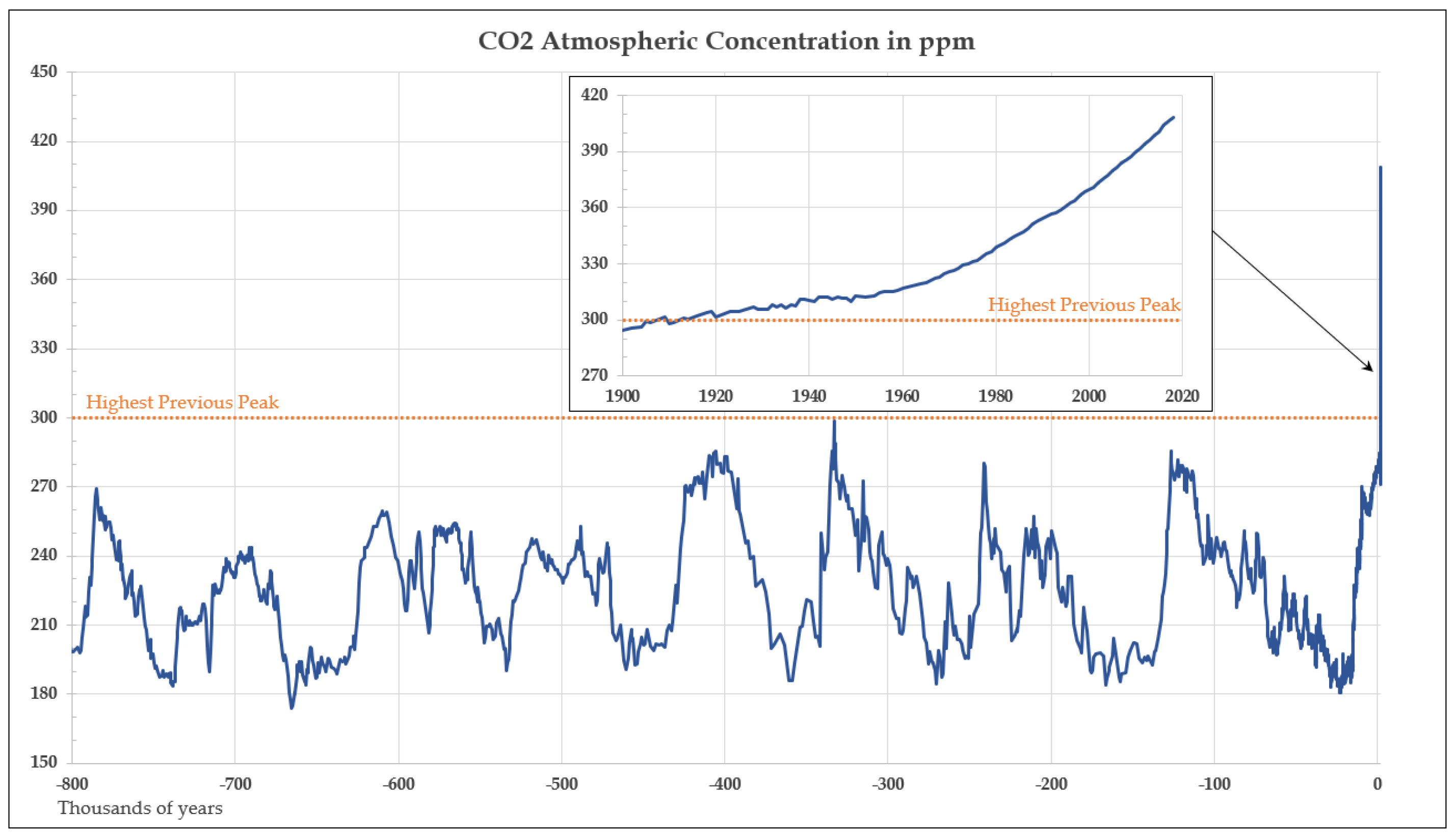
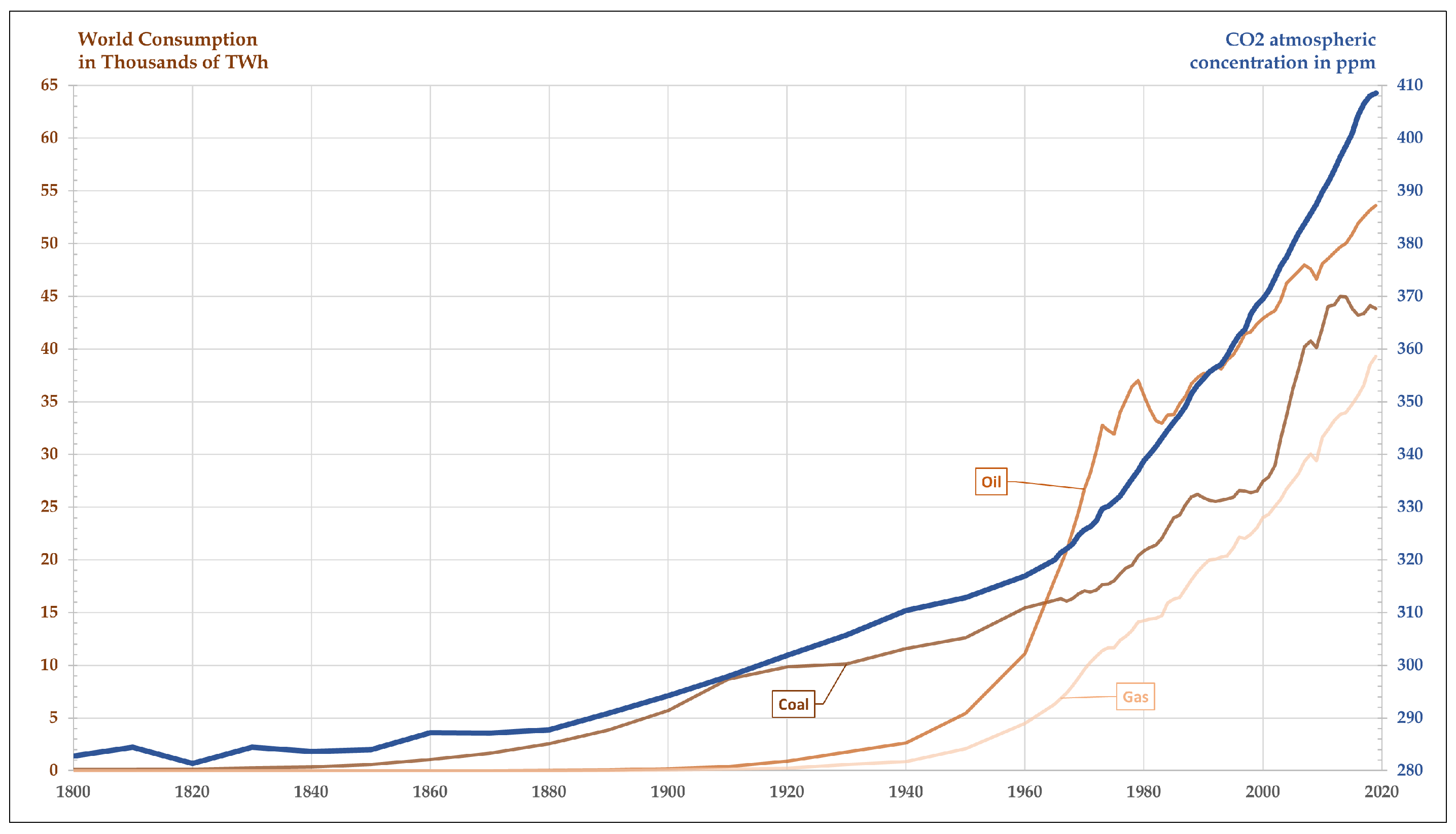
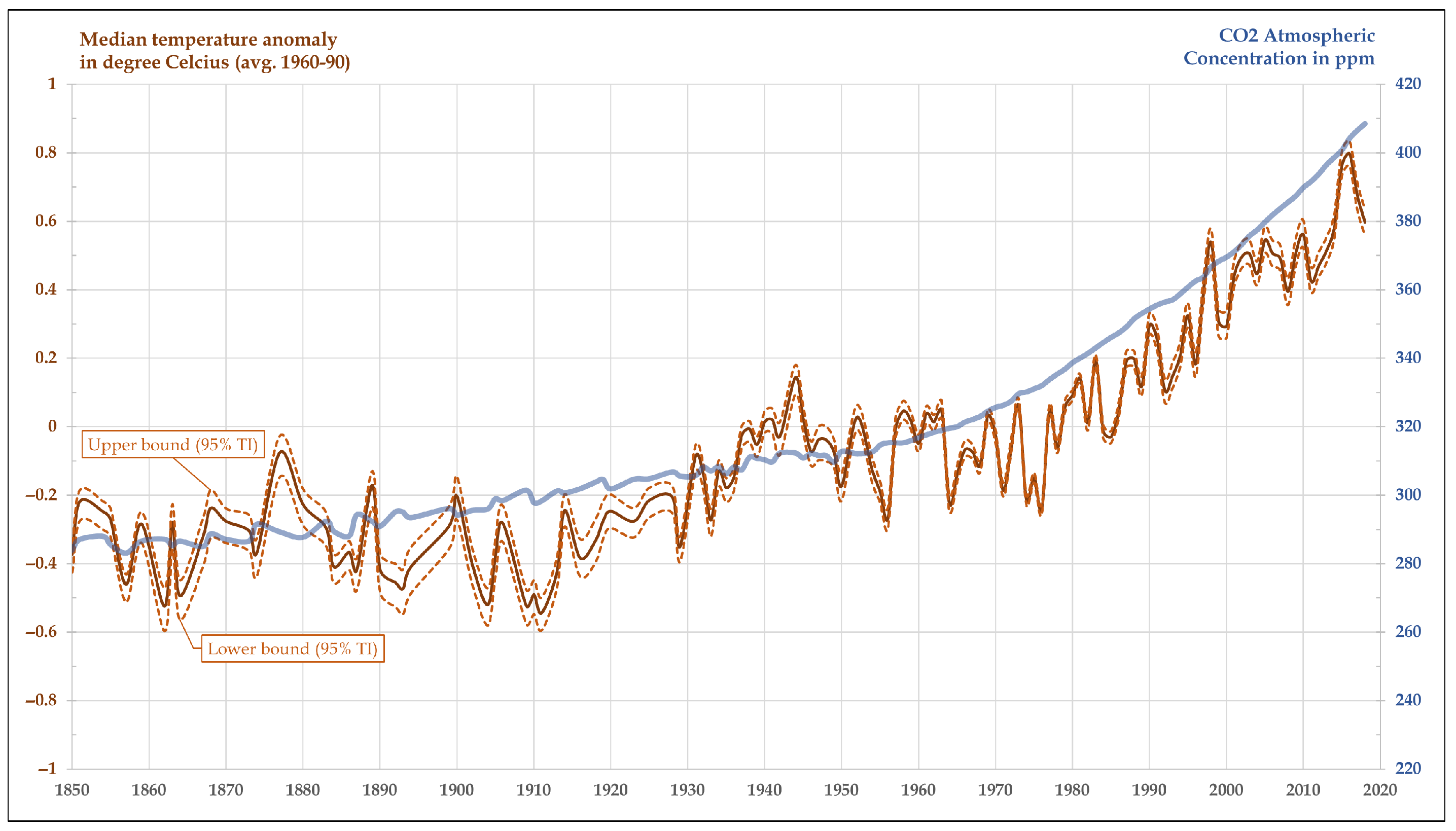
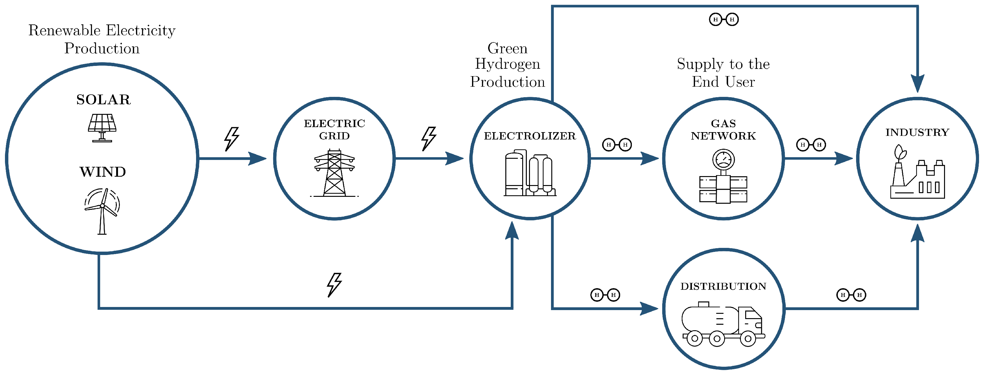
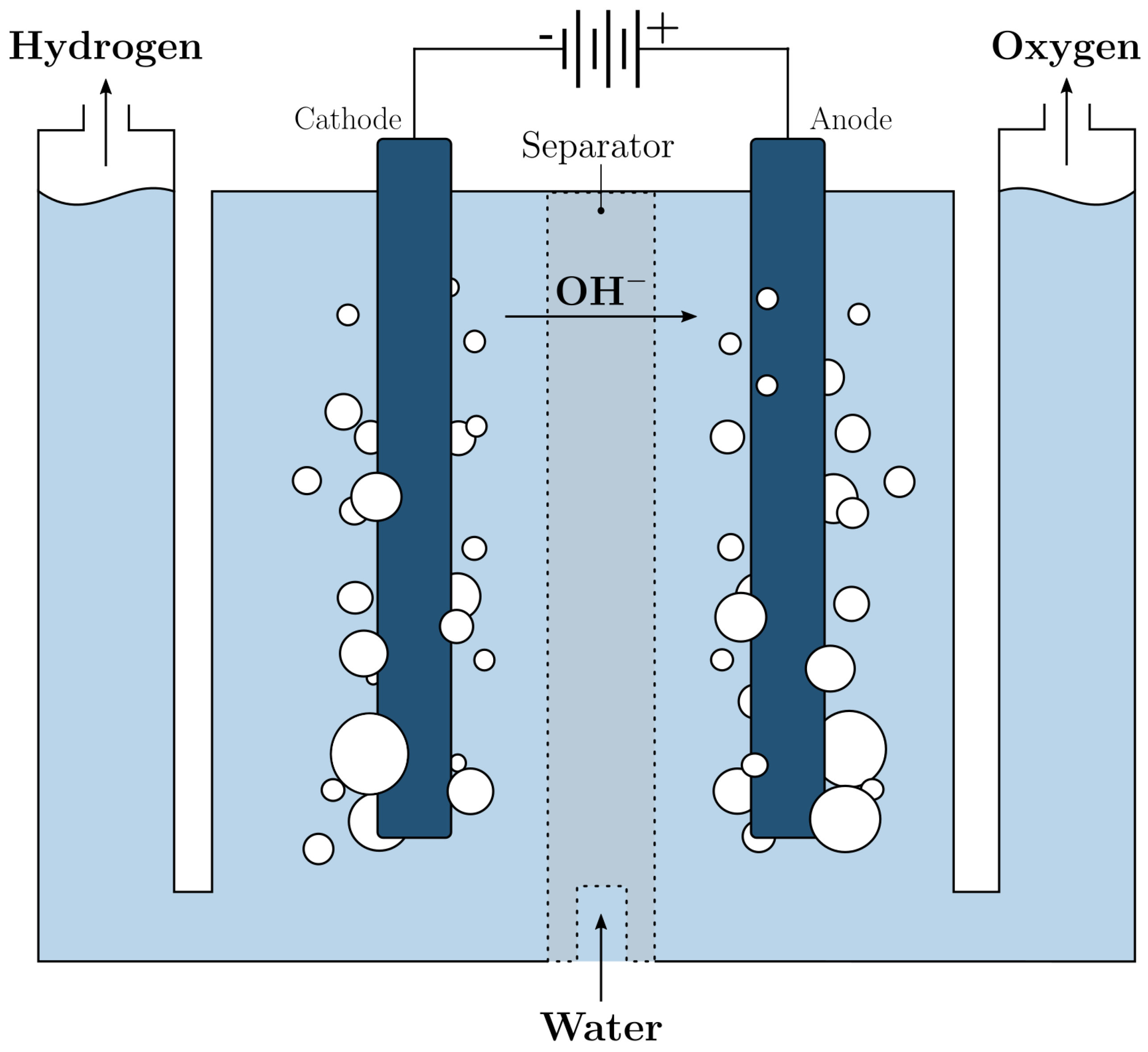