
A Study on Anti-Shock Performance of Marine Diesel Engine Based on Multi-Body Dynamics and Elastohydrodynamic Lubrication


Abstract
:1. Introduction
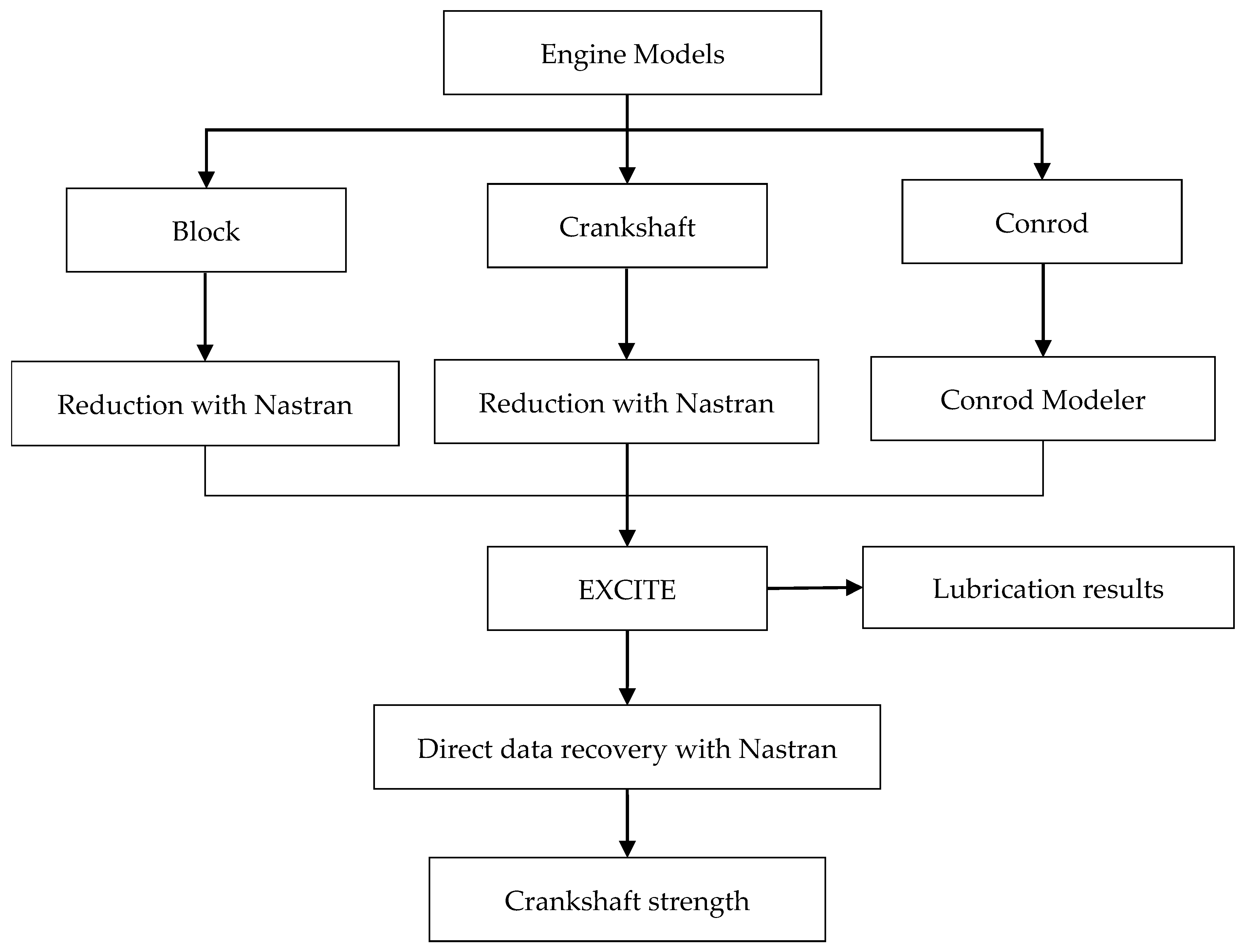
2. Methodology
2.1. Theory
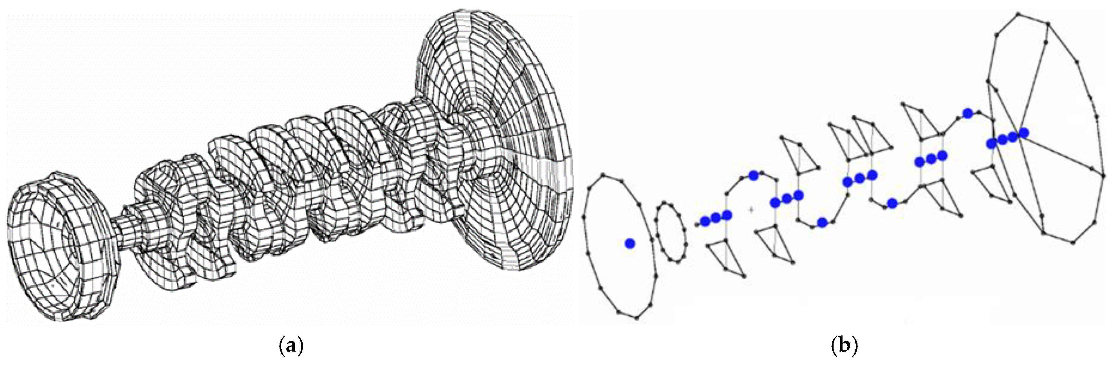
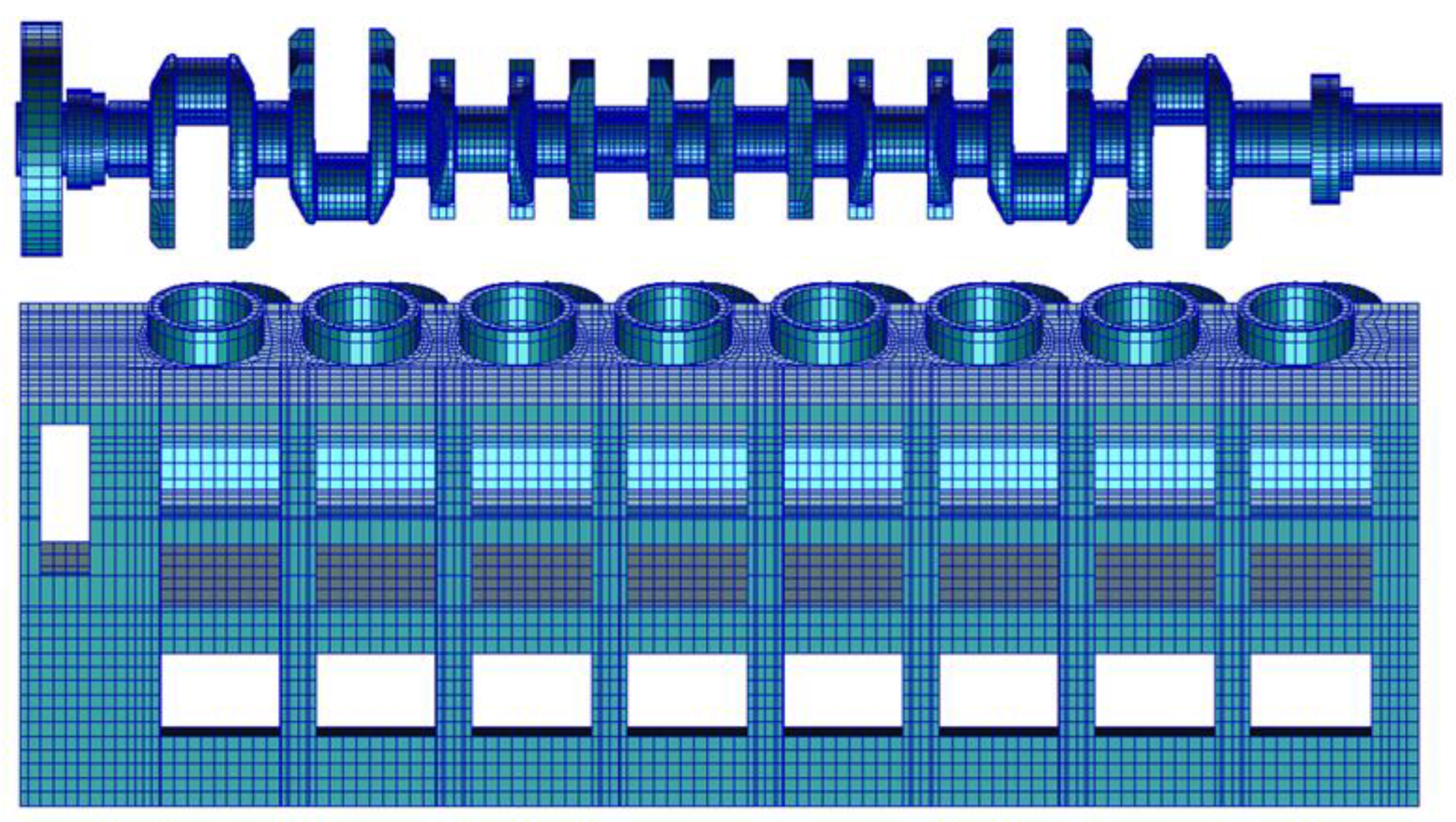
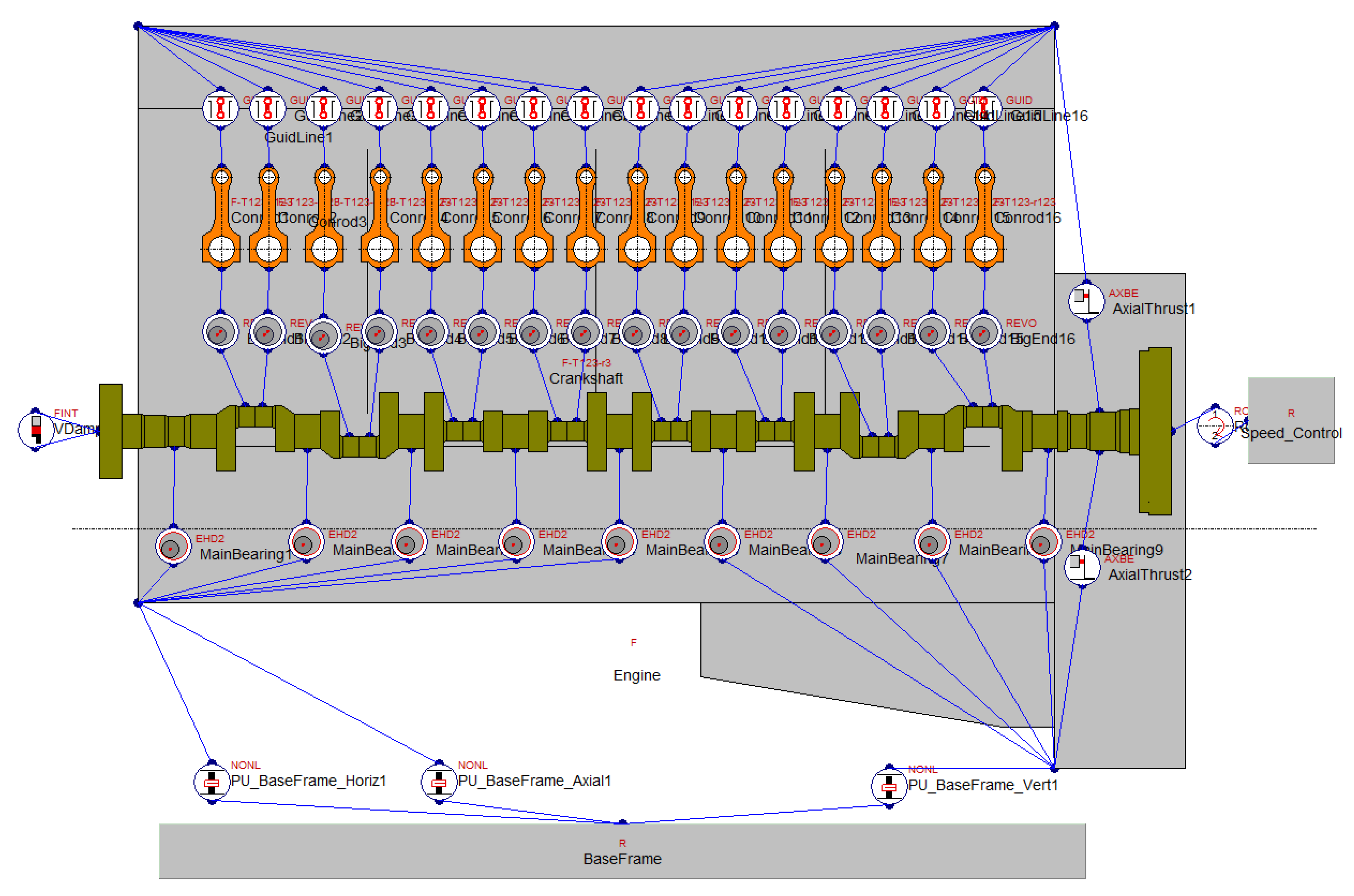
2.2. Simulation Model
2.3. Boundary Conditions
2.4. Key Parameters for Elastohydrodynamic Lubrication Algorithm in External Shock Condition
3. Case Study
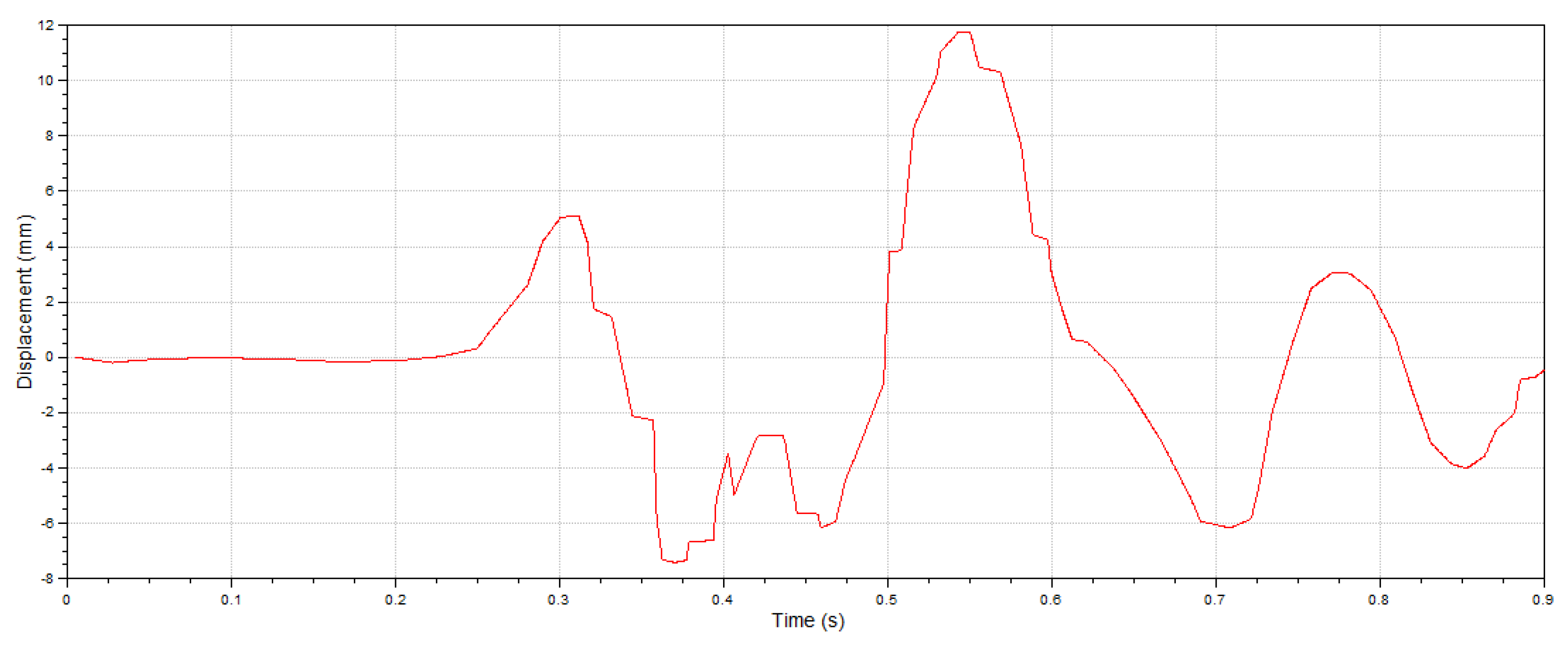
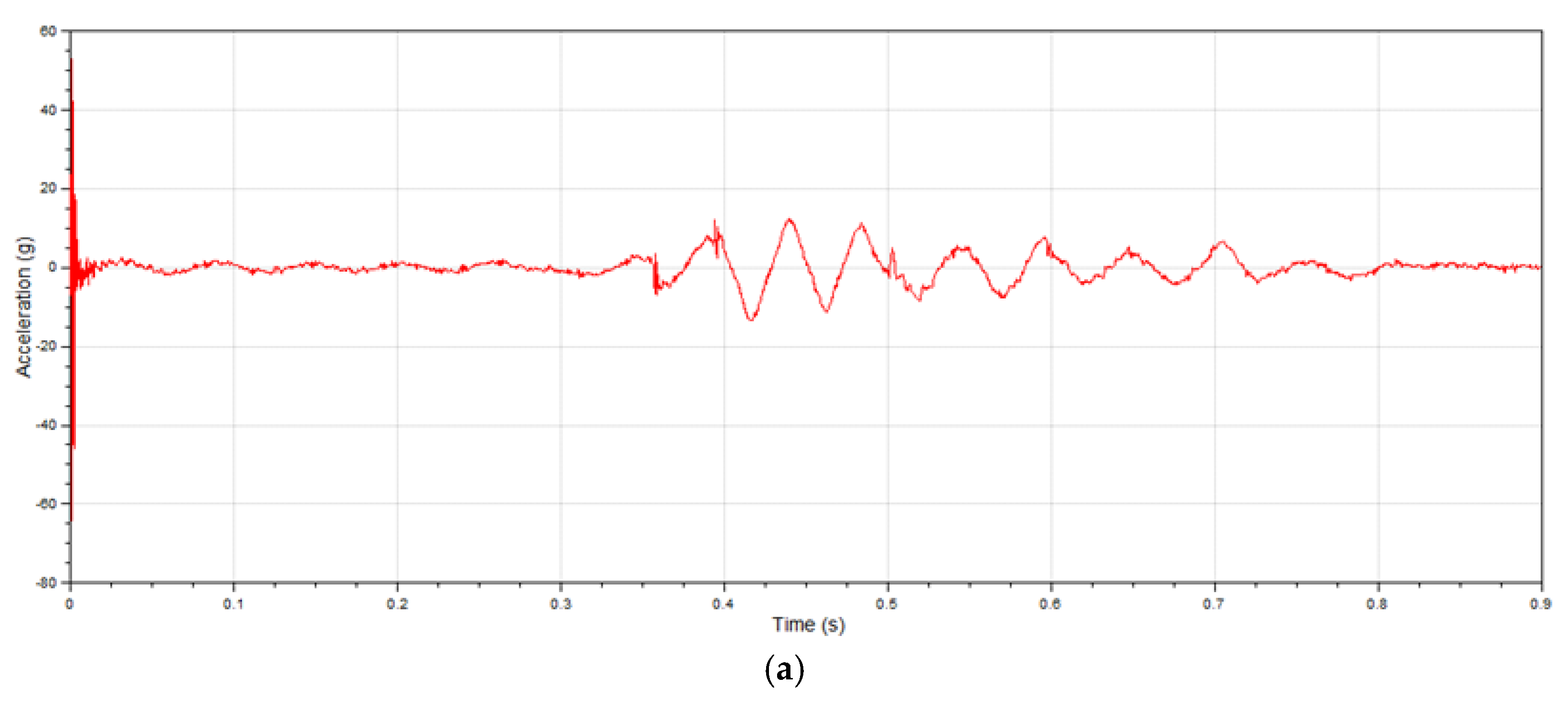
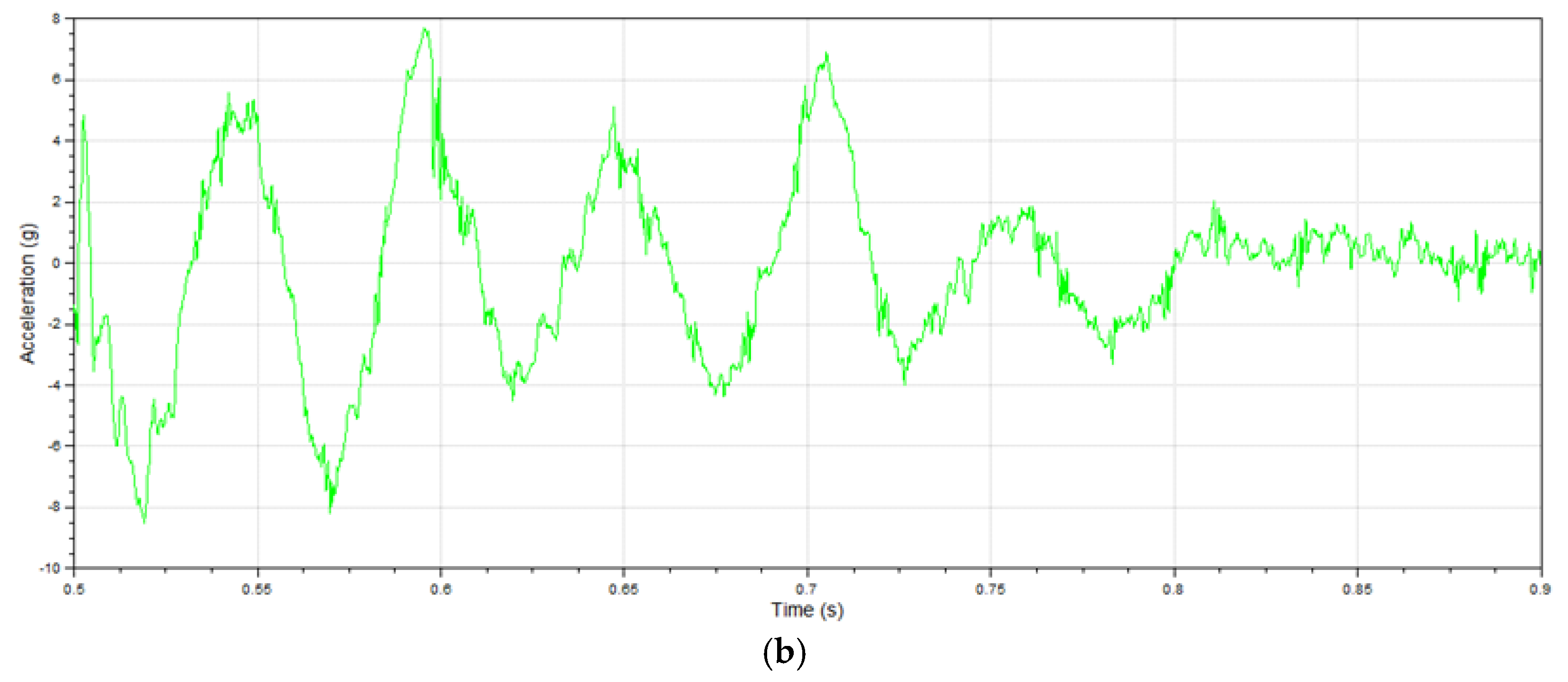
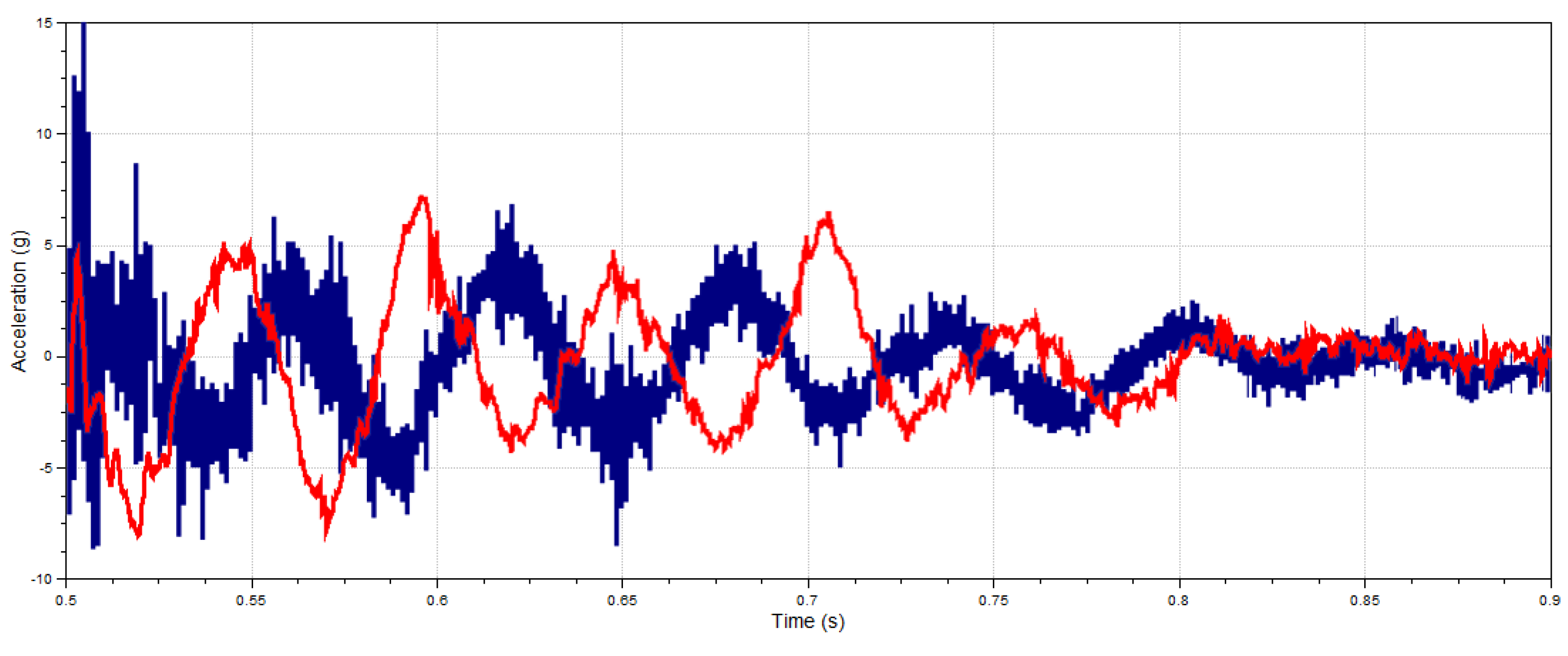
3.1. Comparison of Calculation and Experiment
3.2. Calculation of Diesel Engine with Shock Absorbers in Normal Condition
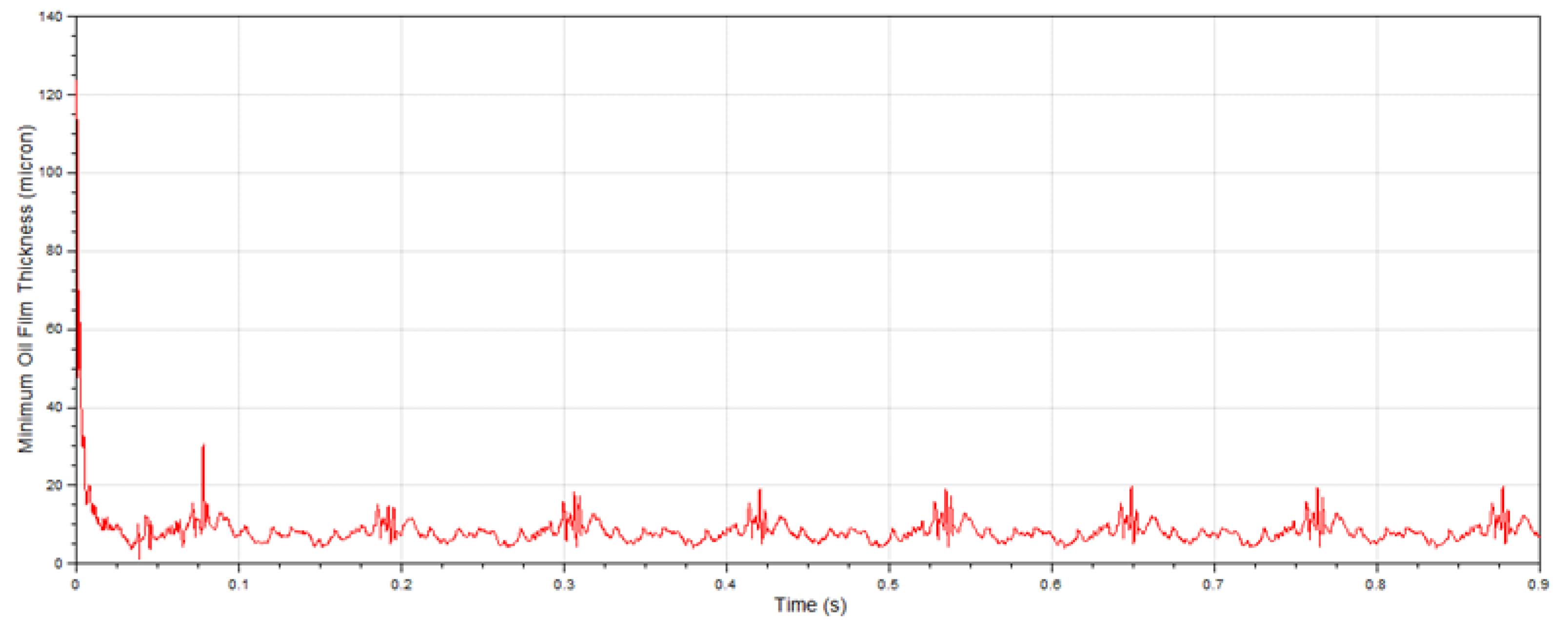
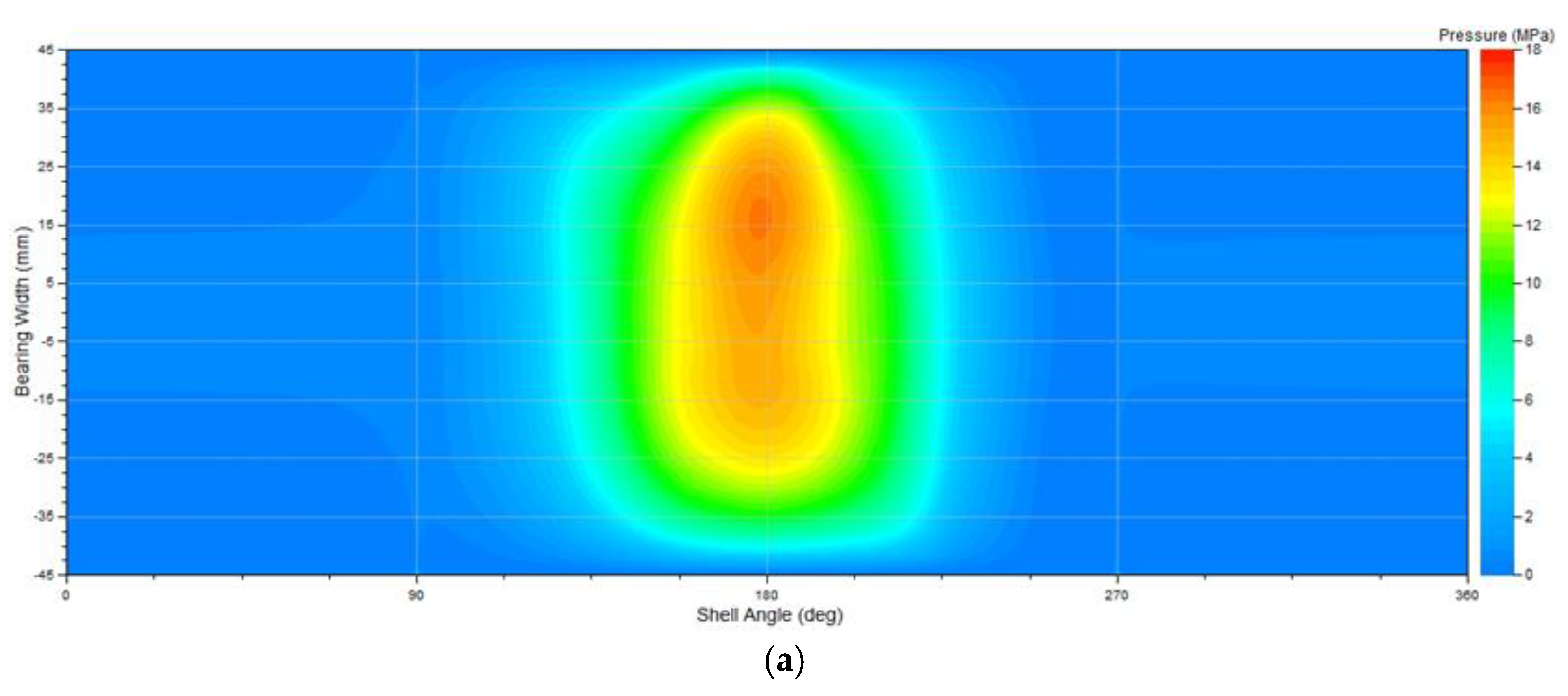
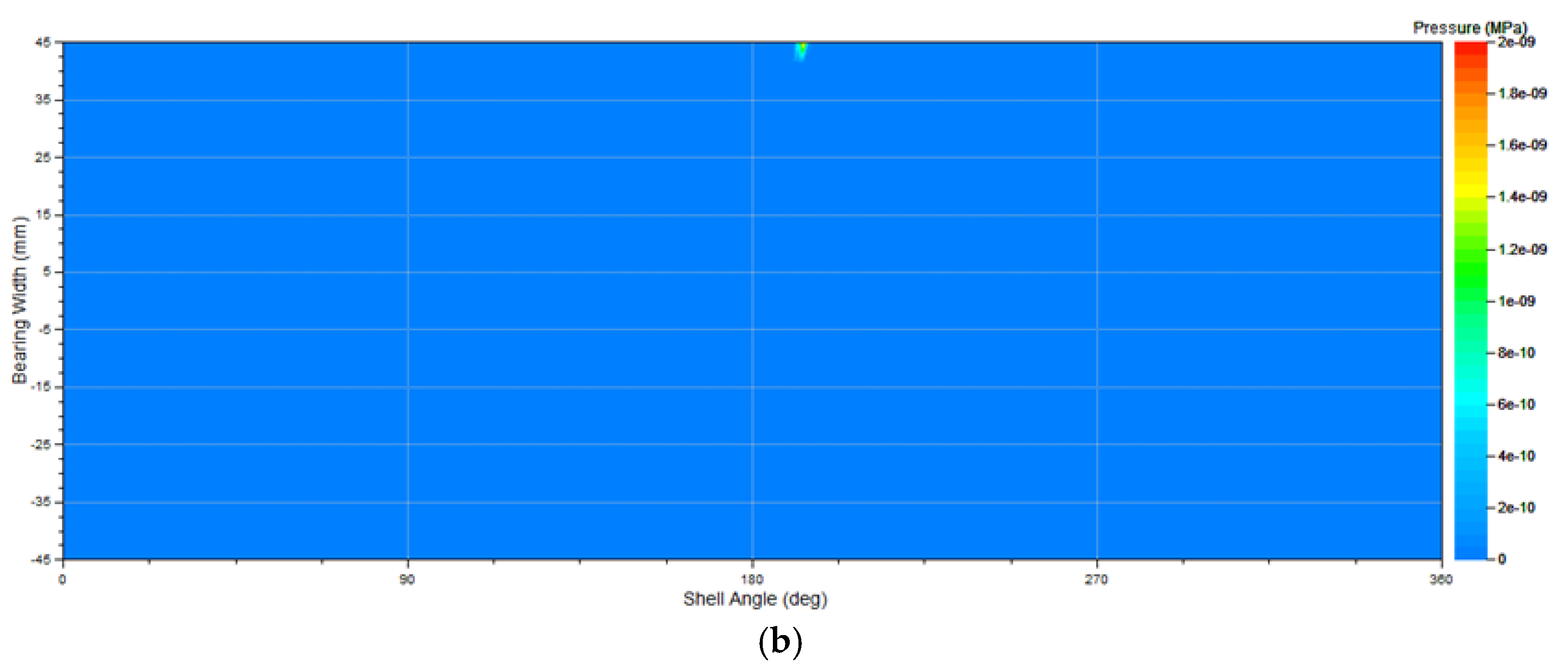
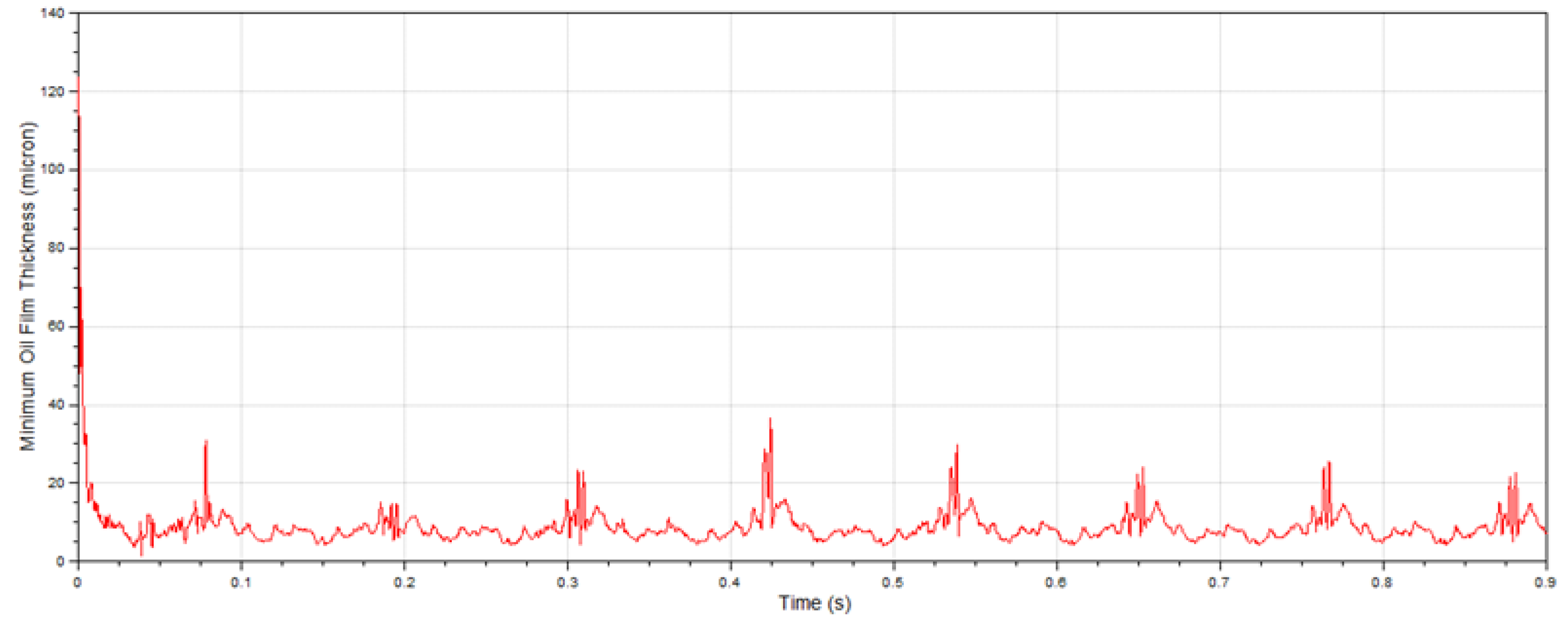
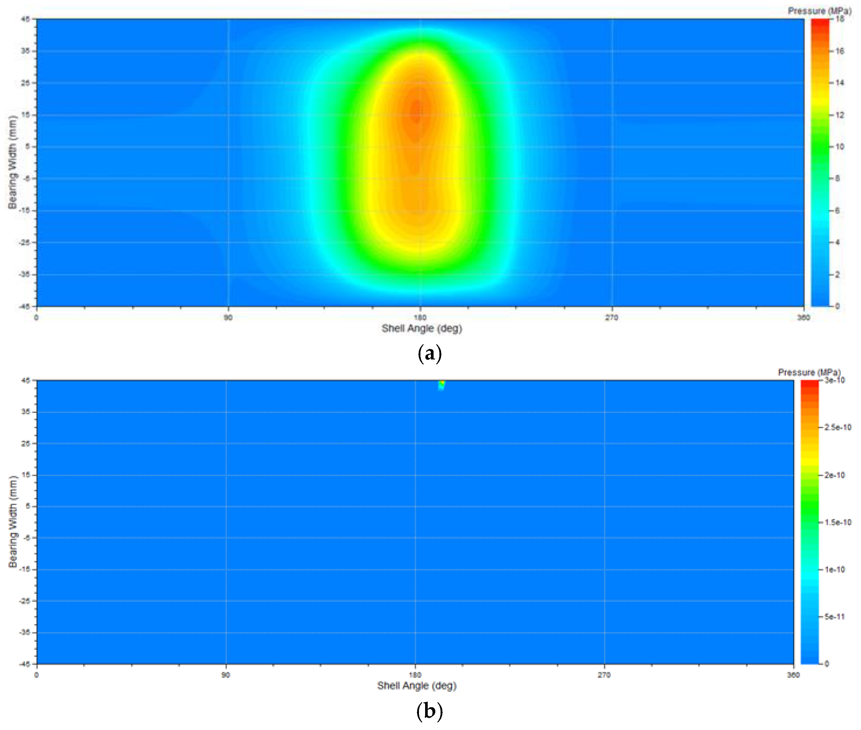
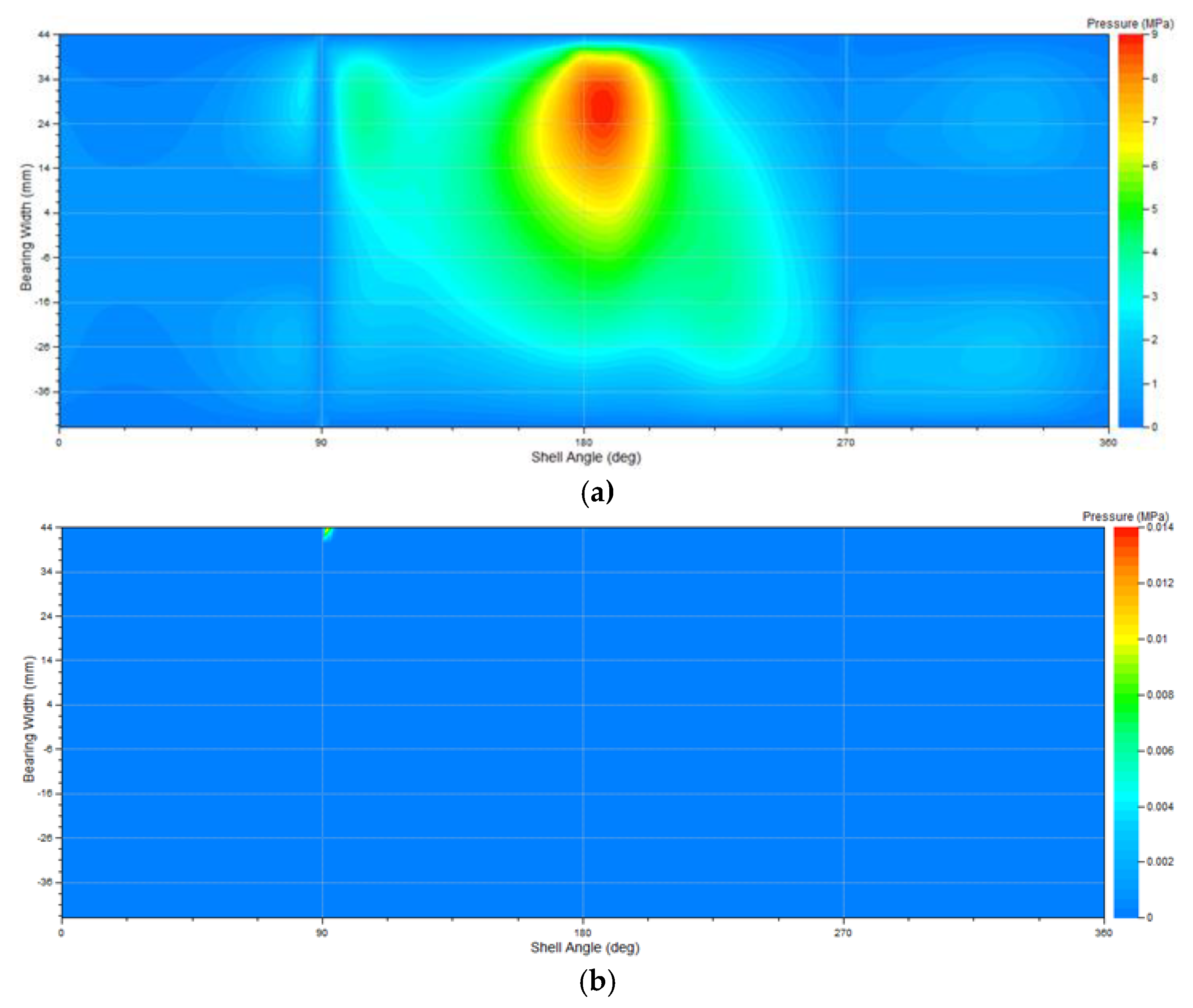
3.2.1. Main Bearing Lubrication of Diesel Engine with Shock Absorbers in Normal Condition
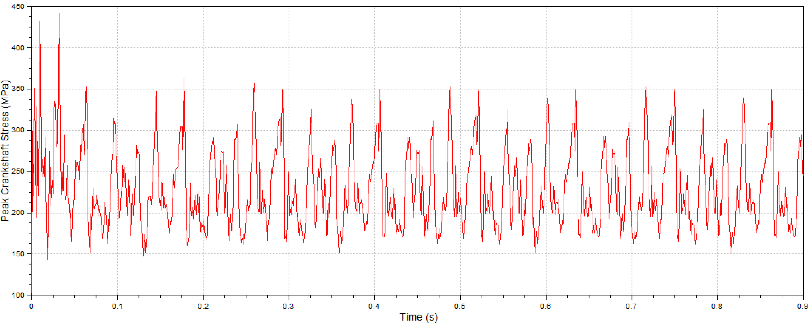
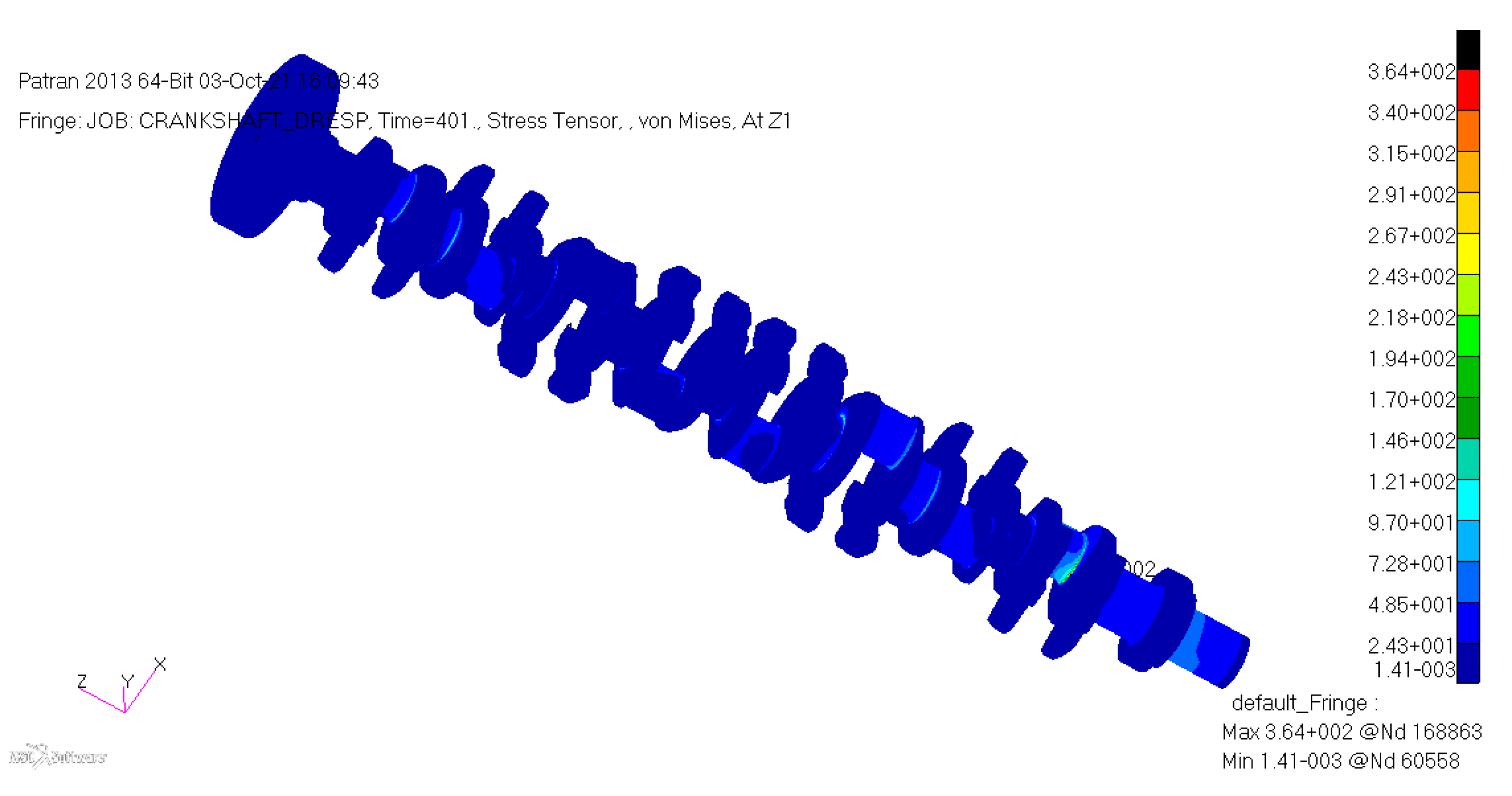
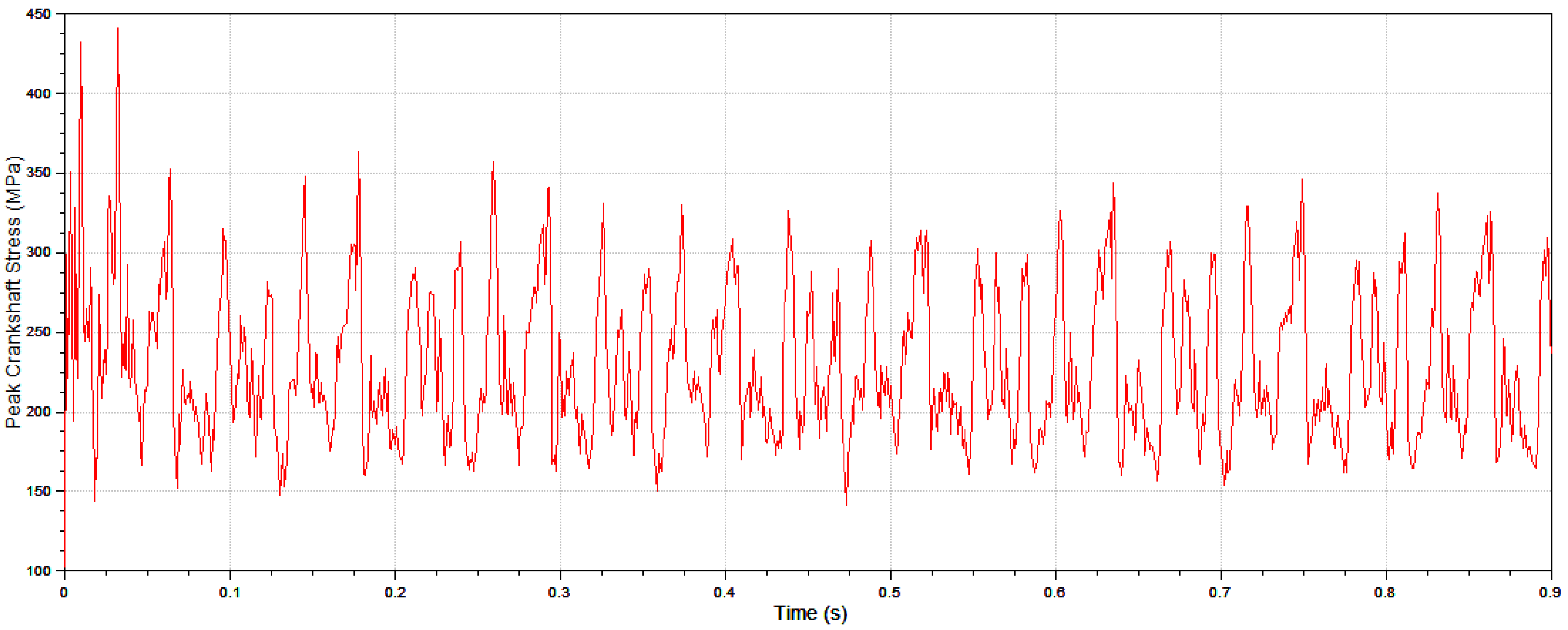
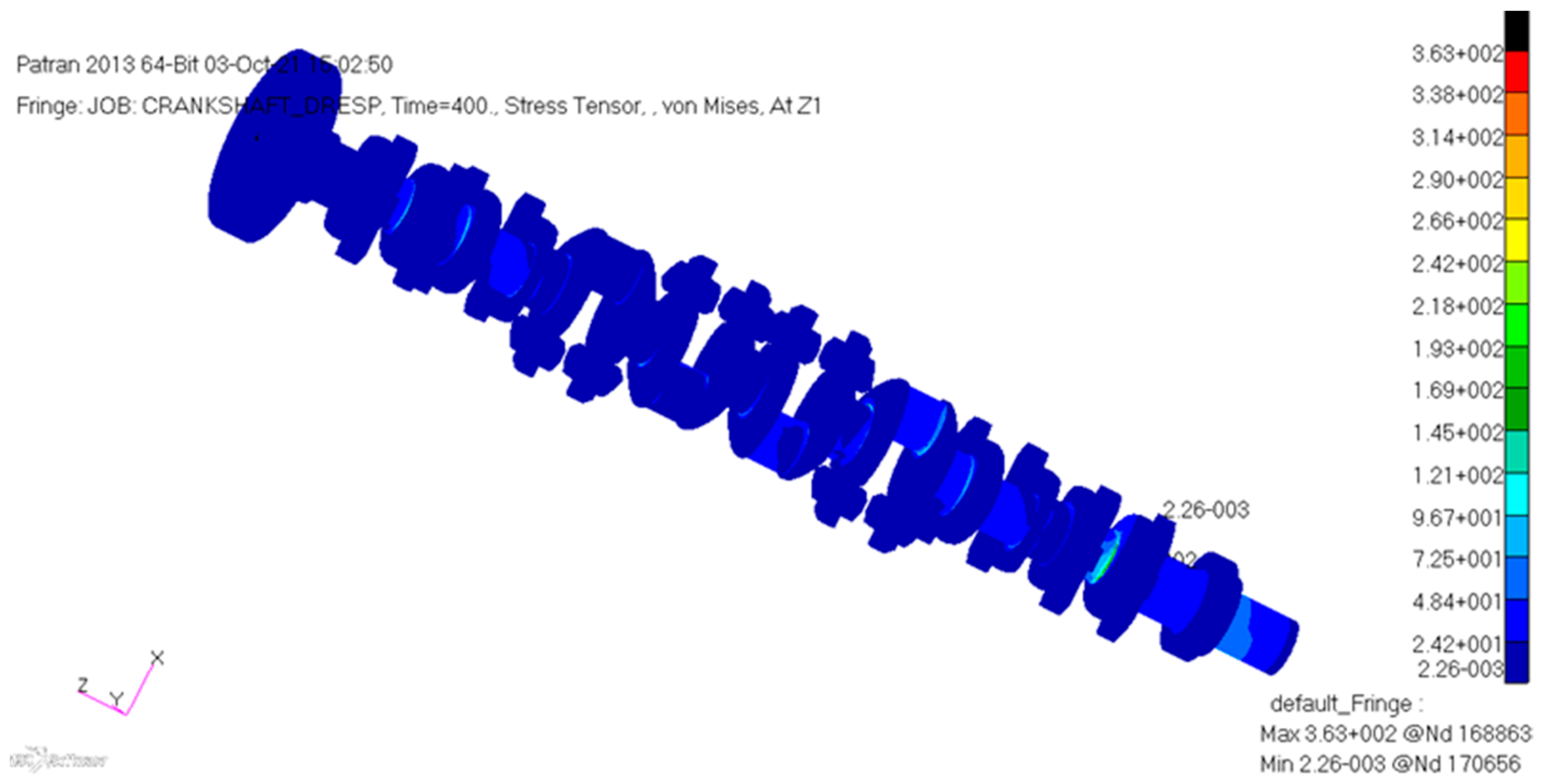
3.2.2. Crankshaft Stress of Diesel Engine with Shock Absorbers in Normal Conditions
3.3. Calculation of Diesel Engine with Shock Absorbers in Impact Condition
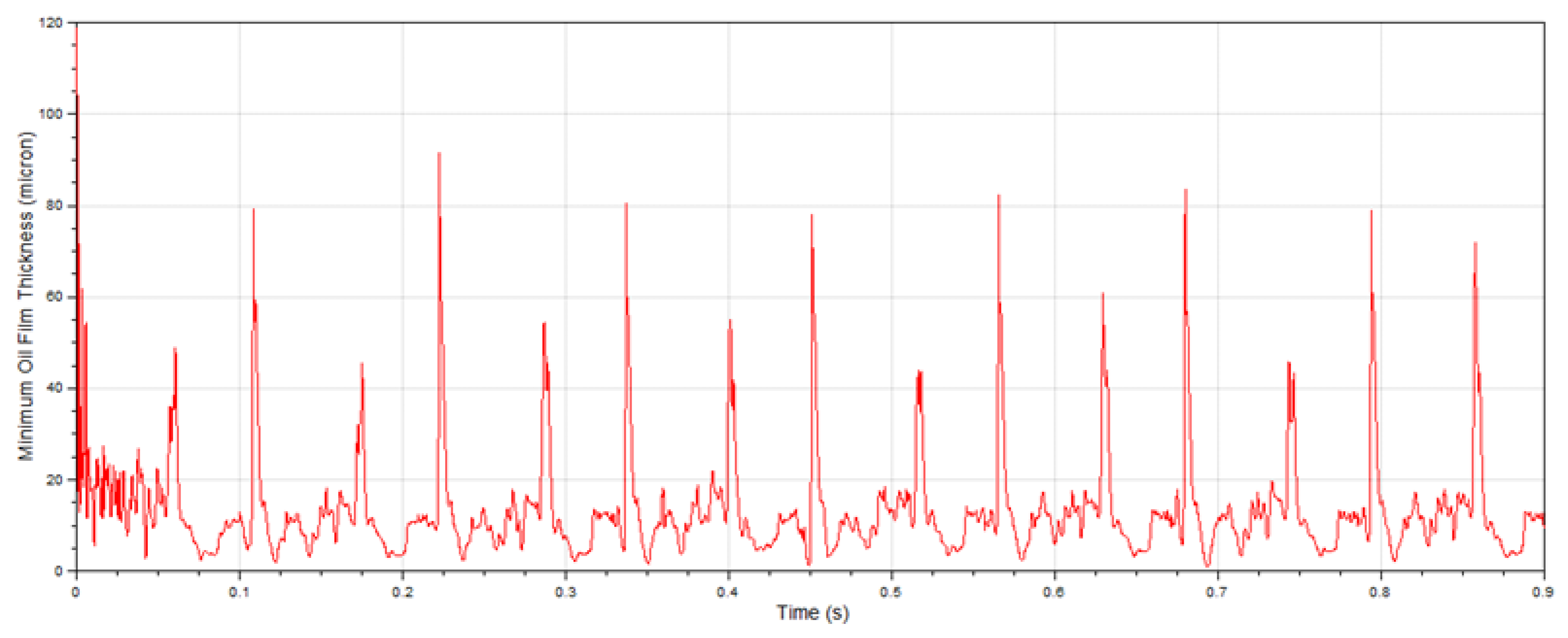
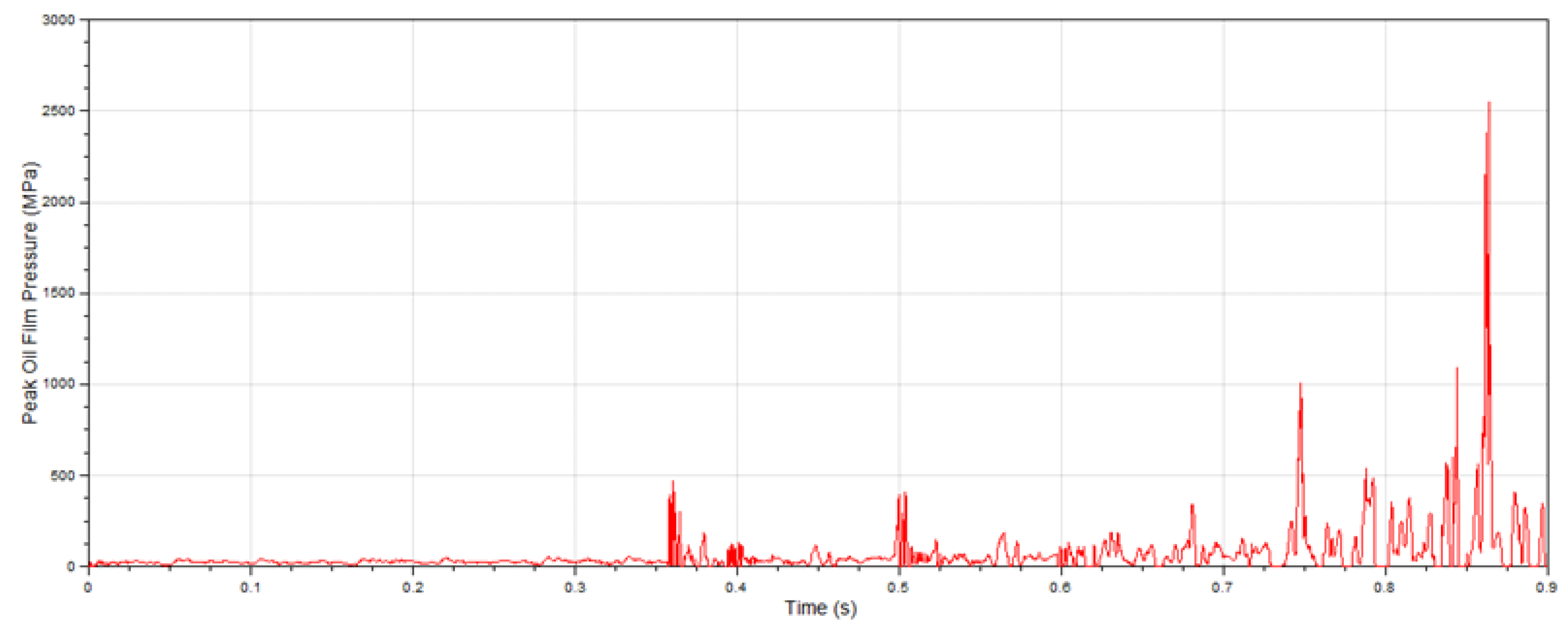
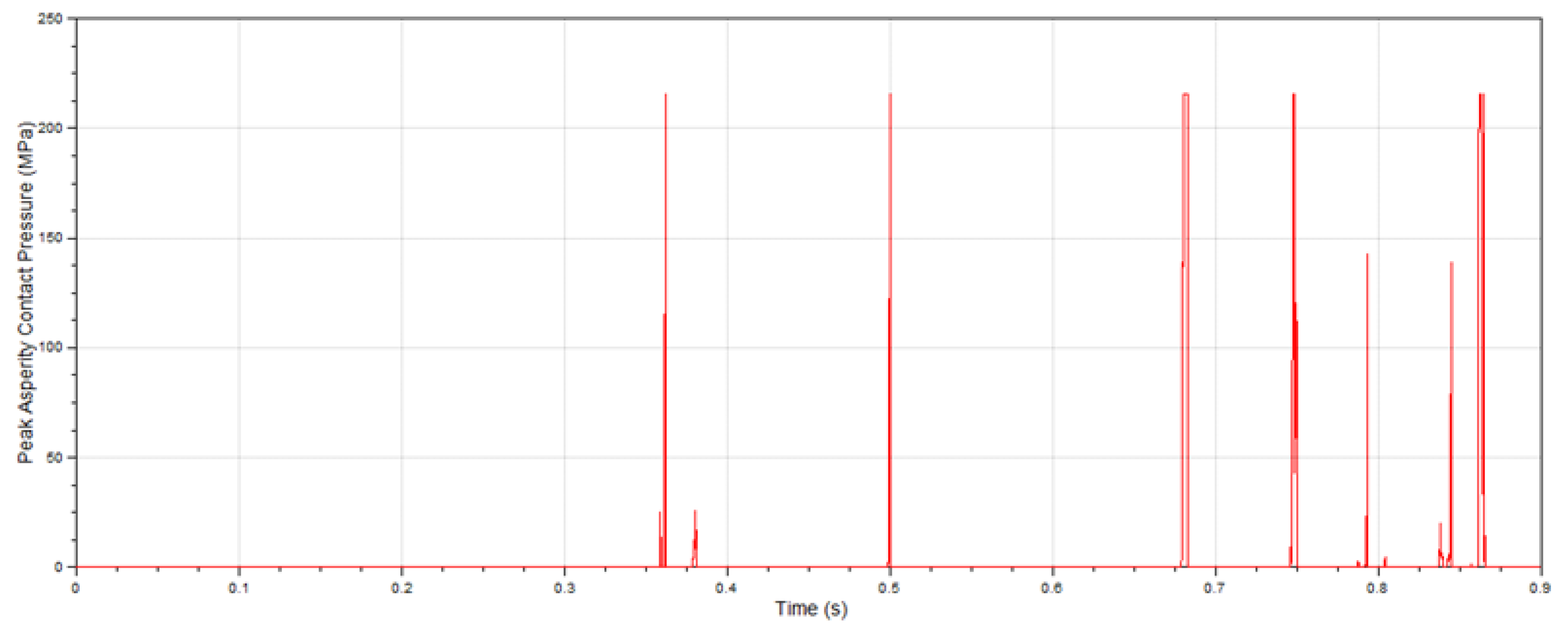
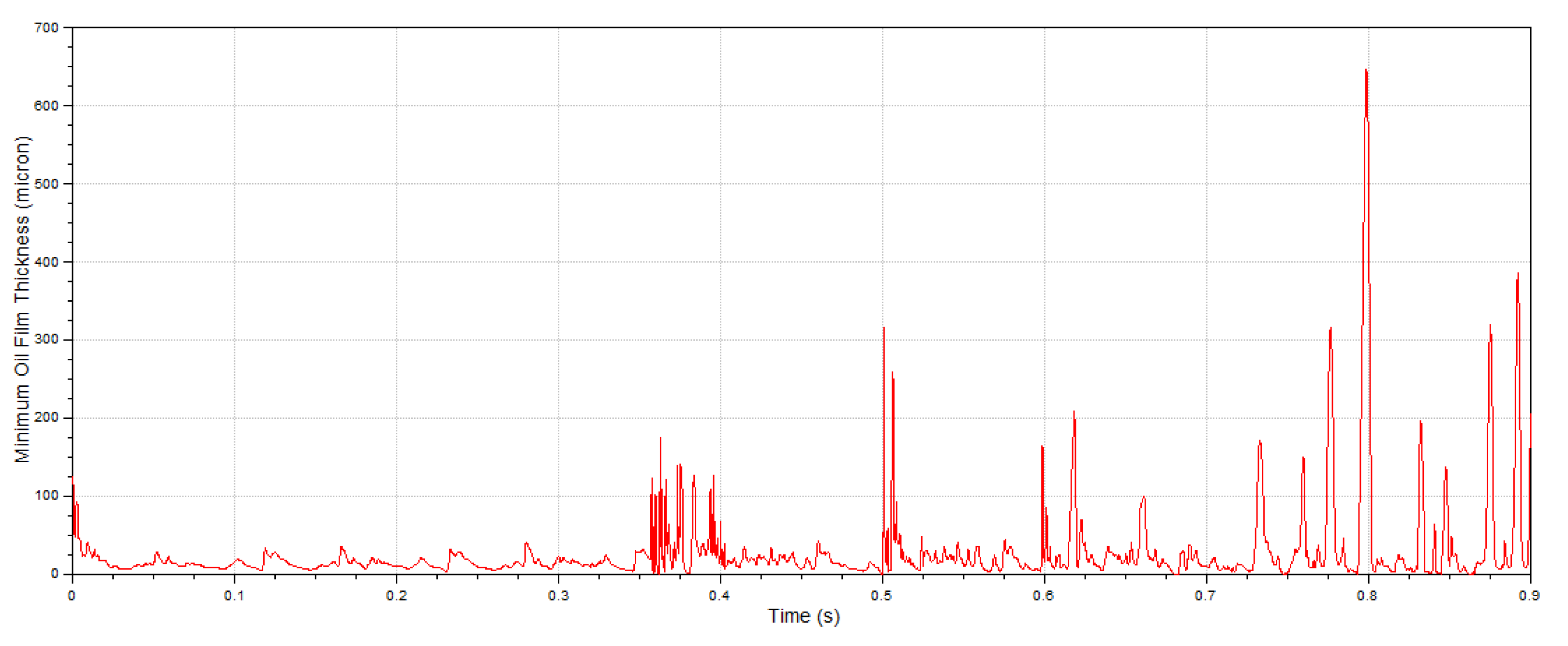
3.3.1. Main Bearing Lubrication of Diesel Engine with Shock Absorbers in Impact Condition
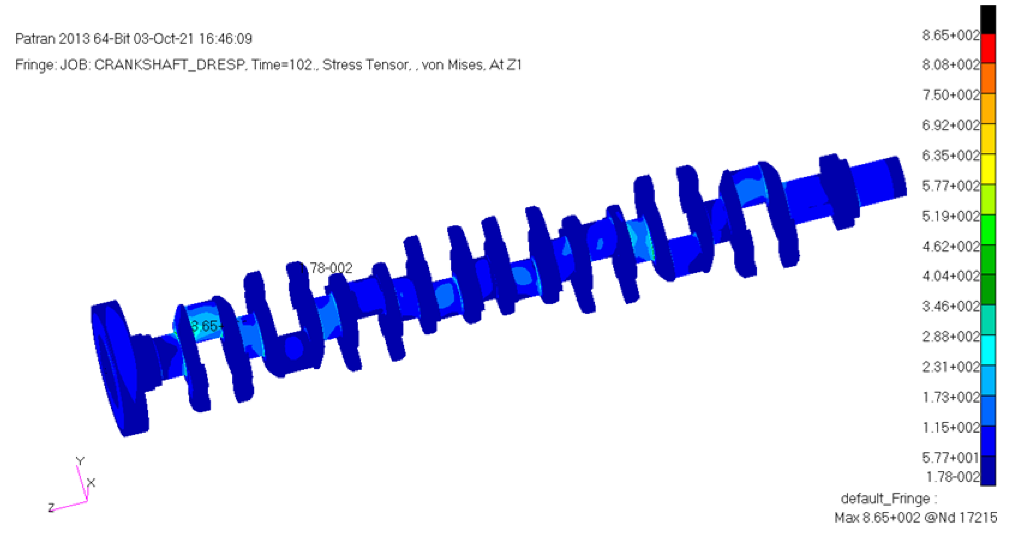
3.3.2. Crankshaft Stress of Diesel Engine with Shock Absorbers in Impact Condition
3.4. Calculation of Diesel Engine without Shock Absorbers in Impact Condition
3.4.1. Main Bearing Lubrication of Diesel Engine without Shock Absorbers in Impact Condition
3.4.2. Crankshaft Stress of Diesel Engine without Shock Absorbers in Impact Condition
4. Conclusions
Author Contributions
Funding
Institutional Review Board Statement
Informed Consent Statement
Data Availability Statement
Acknowledgments
Conflicts of Interest
References
- Liu, J.H. Theory and Its Application of Ship Dynamic Responses to Non-Contact Underwater Explosions. Ph.D. Thesis, China Ship Scientific Research Center, Wuxi, China, March 2002. [Google Scholar]
- Alexander, J.E. Nonlinear system mode superposition given a prescribed shock response spectrum input. In Proceedings of the IMAC-XX Conference and Exposition on Structural Dynamics-Smart Structures and Transducers, Los Angeles, CA, USA, 4–7 February 2002. [Google Scholar]
- James, P.; Roggeman, B. Mechanical shock testing and modeling of PC motherboards. In Proceedings of the IEEE Electronic Components and Technology Conference, Las Vegas, NV, USA, 1–4 June 2004. [Google Scholar]
- Jayson, E.M. Numerical and Experimental Investigations of a Hard Disk Drive Subject to Shock and Vibration. Ph.D. Thesis, University of California, San Diego, CA, USA, 2003. [Google Scholar]
- Wang, Y.; Hua, H.X. Modern Ship Shock Theory and Its Application, 1st ed.; China Science Publishing & Media Ltd.: Beijing, China, 2005; pp. 1–2. [Google Scholar]
- Liu, S.J.; Bao, G.Z.; Chen, H.Q.; Chen, X.C.; Yao, S.G. Shock response analysis of crank and connecting rod mechanism of 12VPA6 marine diesel engine. Chin. Intern. Combust. Engine Eng. 2007, 28, 39–42. [Google Scholar]
- Wang, C.Y.; Chang, H.B.; Zheng, R.B.; Wang, Y. Shock dynamics simulation of crankshaft system based on DYTRAN. Chin. Intern. Combust. Engine Eng. 2009, 30, 87–92. [Google Scholar]
- Ma, B.J.; Zhang, H.; Wang, Z.G. Dynamic analysis of shock response for crank and connecting rod mechanism in diesel engines. Noise Vib. Control 2013, 33, 32–35. [Google Scholar]
- Lu, K.M.; Wang, Y. Analysis of shock dynamics on diesel engine crank and connecting rod mechanism. J. Nav. Univ. Eng. 2011, 23, 84–87. [Google Scholar]
- Ming, Z.J. Analysis for Dynamic Characteristics and Shocking Response of a Diesel Engine Crankshaft System. Master’s Thesis, Dalian University of Technology, Dalian, China, 2008. [Google Scholar]
- Ding, J.H.; Song, Y.L.; Wang, H.; Ren, J.J.; Liu, B. Parallel computing for large scale anti-shock dynamic simulation of diesel engine. J. Vib. Shock. 2014, 33, 163–167. [Google Scholar]
- Zhao, J.H.; Wang, Y.; Gao, H.B.; Sun, Y.P. Shock limited load of equipment and analysis examples. Noise Vib. Control 2012, 32, 120–124. [Google Scholar]
- Gao, H.P.; Song, J.L.; Feng, L.H.; Shen, X.L. Method research of the test point arrangement for marine diesel in anti-shock test. China Meas. Test. 2016, 42, 140–144. [Google Scholar]
- Zhao, J.H.; Wang, Y.; Ji, C.; Yang, Y. Strength analysis of the main fixed assembly of diesel engine subjected to underwater explosion. J. Mech. Strength 2008, 30, 707–712. [Google Scholar]
- Ji, C.; Wang, Y.; Yang, L.; Feng, L.H. Time domain analysis on shock response of main components of diesel. Acta Armamentarii 2011, 32, 391–396. [Google Scholar]
- Wu, W.B. Simulation on anti-shock characteristic of diesel engine. Ship Ocean Eng. 2010, 39, 63–65. [Google Scholar]
- Ji, C.; Wang, Y.; Ao, C.Y.; Wu, J.B. Shock response analysis of marine diesel engine on dynamic operation. Ship Eng. 2010, 32, 13–16. [Google Scholar]
- Wang, Y.; Zhao, J.H.; Du, J.Y.; Mu, C. Simulation on antishock performance of a marine diesel engine by using finite element calculation based on multibody dynamics. J. Vib. Shock. 2009, 28, 87–90. [Google Scholar]
- Xiao, Y.L. Research on Vibration and Shock-Resistant of Marine Diesel. Master’s Thesis, Jiangsu University of Science and Technology, Zhenjian, China, March 2014. [Google Scholar]
- Sun, J.; Gui, C.L.; Wang, J.F.; Pan, Z.D. Analysis of bearing tribology performance considering crankshaft deformation in crankshaft-bearing system. Trans. CSICE 2007, 25, 258–264. [Google Scholar]
- He, Z.X.; Gui, C.L.; Li, Z.; Sun, J. Couple research on dynamics and tribology of crankshaft-bearing system considering misalignment caused by elastic deflection. Trans. Chin. Soc. Agric. Mach. 2007, 38, 5–10. [Google Scholar]
- Marian, M.; Bartz, M.; Wartzack, S.; Rosenkranz, A. Non-dimensional groups, film thickness equations and correction factors for elastohydrodynamic lubrication: A review. Lubricants 2020, 8, 95. [Google Scholar] [CrossRef]
- Marian, M.; Grützmacher, P.; Rosenkranz, A.; Tremmel, S.; Mücklich, F.; Wartzack, S. Designing surface textures for EHL point-contacts-transient 3D simulations, meta-modeling and experimental validation. Tribol. Int. 2019, 137, 152–163. [Google Scholar] [CrossRef]
- Yang, F.Q.; Liu, X.; Jiang, J.W. Current progress of elasto-hydrodynamic lubrication on mechanical parts with higher pairs. Lubr. Eng. 2019, 44, 135–140. [Google Scholar]
- Zhao, J.J.; Wang, Y.Q. Present situation and development trend of elastohydrodynamic lubrication for modified helical gear. J. Mach. Des. 2018, 35, 53–57. [Google Scholar]
- Xue, H.; Wang, J.G.; Hong, Y.F. Elastohydrodynamic lubrication analysis on line contact lubricated with grease. Lubr. Eng. 2017, 42, 12–16. [Google Scholar]
- Zhou, Y.B.; Wang, Y.Q.; Wei, C.; Long, S.W. Influence of interfacial modification on EHL of journal bearing. J. Mech. Transm. 2019, 43, 27–31. [Google Scholar]
- Shen, J.L.; Xue, Z.T.; Heng, C.F.; Liu, X.J. Elastic deformations of surface under EHL point contact. China Mech. Eng. 2019, 30, 1696–1702. [Google Scholar]
- Zhang, T.; Chen, X.Y.; Chen, S.J.; Gu, J.M. Study on starved oil elastohydrodynamic lubrication model and experiments of multi-point contacts. Lubr. Eng. 2020, 45, 125–134. [Google Scholar]
- Jin, W.; Guo, F.; Jing, Z.G. Reconsideration of Hamrock–Dowson Formula for Elliptic Contact Elastohydrodynamic Lubrication. 2021. Available online: https://kns.cnki.net/kcms/detail/62.1095.O4.20210220.1414.025.html (accessed on 20 February 2021).
- Meng, F.M.; Zhang, W.M. Elastohydrodynamic lubrication of elliptical contact considering effect of inertia of lubrication film. Tribology 2019, 39, 585–592. [Google Scholar]
- Yang, G.D.; Cao, Y.P.; Zhang, W.P.; Ming, P.J.; Li, L.Y. Coupling analysis of thermal elastic hydrodynamic lubrication of functionally graded main bearing. Trans. CSICE 2021, 39, 459–465. [Google Scholar]
- Li, C.J.; Zhao, J.S.; Zhu, G.X.; Li, X.C.; Zhang, G.D. Influence of crankshaft journal profile on lubrication of main bearing. Lubr. Eng. 2021, 46, 51–56. [Google Scholar]
- Ren, P.R.; Zuo, Z.X.; Cheng, Y.; Zhang, Z.W. Effect of the side bolts on the dynamic and static characteristics of the internal combustion engine’s main bearing. J. Mach. Des. 2020, 37, 14–20. [Google Scholar]
- Teng, X.B.; Zhang, J.D.; Ye, W.Q. Characteristic analysis of diesel engine main bearing lubrication based on thermo-elastic hydrodynamic pressure. Ship Eng. 2016, 238, 61–64. [Google Scholar]
- Shi, L.; Zhang, H.B.; Li, L.T.; Liang, G. Finite element analysis and structural optimization of main bearing block for a marine diesel engine. Diesel Engine 2016, 38, 20–24. [Google Scholar]
- Li, H.; Zhao, J.S.; Cui, S.X.; Zhang, Z.W.; Yang, S.B. Influence of surface profile on lubrication performance of engine main bearings. Lubr. Eng. 2018, 43, 49–54. [Google Scholar]
- Zhou, W.; Liao, R.D. Thermo-elasto-hydrodynamic mixed lubrication analysis of main bearing for high power-density diesel engine. Trans. CSICE 2016, 34, 370–378. [Google Scholar]
- Liu, C.P.; Zhao, B.; Li, W.; Lu, X. Effects of bushing profiles on the elastohydrodynamic lubrication performance of the journal bearing under steady operating conditions. Mech. Ind. 2019, 20, 207–220. [Google Scholar] [CrossRef]
- Zhang, J.H.; Zhang, G.C.; He, Z.P.; Ma, L.; Ma, W.P. Optimization of crankshaft-bearing lubricating characteristics based on orthogonal experiment and neural network. Trans. CSICE 2011, 29, 461–467. [Google Scholar]
- Wang, J.; Zhang, J.H.; Lin, J.W.; Ma, L. Study on lubrication performance of journal bearing with multiple texture distributions. Appl. Sci. 2018, 8, 244. [Google Scholar] [CrossRef] [Green Version]
- Liu, K.; Chen, R.; Zhao, J.H.; Wang, F.Y.; Zhao, B. Lubrication characteristics analysis and variable wall thickness optimization design of a diesel engine main bearing under different crankshaft balance ratios. Chin. Intern. Combust. Engine Eng. 2021, 42, 54–61. [Google Scholar]
- Yan, X.Y.; Cui, Y.; Fu, Y.; Cheng, D.; Dong, J.J. Elasto-hydrodynamic lubrication analysis of main bearing for a low speed marine diesel engine. Diesel Engine 2020, 42, 22–29. [Google Scholar]
- Yan, X.Y.; Cui, Y.; Fu, Y.; Cheng, D.; Dong, J.J. Stiffness matching design of bedplate for low speed two-stroke marine diesel engine based on dynamics and coupling lubrication. Ship Eng. 2019, 41, 52–58. [Google Scholar]
- Zhou, J.H.; Xu, M.; Wang, B. A novel method studying the effects of journal straightness in three-dimensional space on lubrication of bearing. In Proceedings of the SAE World Congress Experience, Detroit, MI, USA, 4–6 April 2017. [Google Scholar]
- Feng, X.K.; Yang, L.H. Analysis on thermoelasto-hydrodynamic lubrication characteristics of tilting pad thrust bearing under heavy load. J. Aerosp. Power 2021, 36, 1861–1870. [Google Scholar]
- Qian, W.D.; Jin, G.; Tang, L.M. Lubrication characteristic analysis of three-dimensional thermal-elastic flow for the dynamic pressure thrust bearing. Pump Technol. 2020, 2020, 16–21. [Google Scholar]
- Wang, J.X.; Ni, X.K.; Han, Y.F.; Xiang, G.; Xiao, K. Mixed thermoelastohydrodynamic lubrication investigation of misaligned journal bearing. J. Cent. South Univ. Sci. Technol. 2019, 50, 2425–2434. [Google Scholar]
- Mourelatos, Z.P. A crankshaft system model for structural dynamic analysis of internal combustion engines. Comput. Struct. 2001, 79, 2009–2027. [Google Scholar] [CrossRef]
- Offner, G. Simulation of the dynamics of internal combustion engines considering oil film lubricated contacts. In Proceedings of the European Congress on Computational Methods in Applied Sciences and Engineering, Vienna, Austria, 10–14 September 2012. [Google Scholar]
- Ma, M.T.; Offner, G.; Loibnegger, B.; Priebsch, H.H.; McLuckie, I. A fast approach to model hydrodynamic behavior of journal bearings for analysis of crankshaft and engine dynamics. In Proceedings of the 30th Leeds–Lyon Symposium on Tribology, Lyon, France, 2–5 September 2003. [Google Scholar]
- Caika, V.; Bukovnik, S.; Offner, G.; Bartz, W.J. Elasto-hydrodynamic journal bearing model with pressure, temperature and shear rate dependent viscosity. In Proceedings of the International Conference on Tribology (AITC-AIT), Parma, Italy, 20–22 September 2006. [Google Scholar]
- Caika, V.; Offner, G.; Bukovnik, S.; Bartz, W.J. Modeling of shear thinning effects in EHD lubrication of combustion engine journal bearings. In Proceedings of the European Conference on Tribology (ECOTRIB), Ljubljana, Slovenia, 12–15 June 2007. [Google Scholar]
- Priebsch, H.H.; Affenzeller, J.; Kuipers, G. Prediction technique of vibration and noise in engines. In Proceedings of the IMechE Conference on Quiet Resolutions: Powertrain and Vehicle Noise Refinement, London, UK, 9–11 October 1990. [Google Scholar]
- Priebsch, H.H.; Affenzeller, J.; Gran, S. Prediction technique for stress and vibration of non-linear supported rotating crankshafts. J. Eng. Gas Turbines Power 1993, 115, 711–720. [Google Scholar] [CrossRef]
- Parikyan, T.; Priebsch, H.H. Structured model of crankshaft in the simulation of engine dynamics with AVL EXCITE. In Proceedings of the ASME Internal Combustion Engine Division Fall Technical Conference, Argonne, IL, USA, 23–26 September 2001. [Google Scholar]
- Greenwood, J.A.; Williamson, J.B.P. The contact of two nominally flat surfaces. Proc. Roy. Soc. 1966, 295, 300–319. [Google Scholar] [CrossRef]
- Greenwood, J.A.; Tripp, J.H. The contact of two nominally flat rough surfaces. Proc. Inst. Mech. Eng. 1971, 185, 48–71. [Google Scholar] [CrossRef]
- Keil, A.H. The Response of Ships to Underwater Explosions; Armed Services Technical Information Agency: Arlington, VA, USA, 1961. [Google Scholar]
- EHD Reference Manual of AVL EXCITE Power Unite Software Help Documents.
- Mou, S.K. Analysis and improvement of calculating results for 16V240ZJB diesel engine bearings. Diesel Locomot. 1995, 1995, 30–35. [Google Scholar]
- Ji, C.; Wang, Z.G.; Wang, Y.; Zhao, J.H. Anti-shock capability of marine diesel in ship shock trial. Ship Sci. Technol. 2010, 32, 27–30. [Google Scholar]


| Item | Crankshaft | Block |
|---|---|---|
| Length (mm) | 3756 | 3594 |
| Width (mm) | 672 | 1385 |
| Height (mm) | 672 | 1288.2 |
| Item | Parameter |
|---|---|
| Type of engine layouts | V-type |
| Engine type | 4 stroke |
| Number of cylinders | 16 |
| Bore (mm) | 240 |
| Stroke (mm) | 275 |
| Rated power (kW) | 3240 |
| Dry weight (kg) | 22,600 |
| Rated speed (r/min) | 1000 |
| Over 10% speed (r/min) | 1100 |
| Mean effective pressure (MPa) | 1.82 |
| Maximum blast pressure (MPa) | 13.37 |
| Item | Parameters |
|---|---|
| Main bearing width (mm) | 83 (No. 1 Bearing) 90 (No. 2–8 Bearing) 88 (No. 9 Bearing) |
| Main journal diameter (mm) | 220 |
| Main bearing radial clearance (mm) | 0.125 |
| Groove width on upper bearing bush (mm) | 22 |
| Diameter of bore on main journal (mm) | 20 |
| Oil type | 4th generation locomotive lubricants |
| Kinematic oil viscosity at 100 °C (mm2/s) | 14.7 |
| Kinematic oil viscosity at 40 °C (mm2/s) | 146.7 |
| Oil density (Kg/m3) | 896.2 |
| Oil temperature (°C) | 88 |
| Lubrication oil supply pressure (MPa) | 0.49 |
| Surface roughness of main journal Rrms (μm) | 0.5 |
| Surface roughness of main bearing bush Rrms (μm) | 1 |
| Item | Stiffness (kN/mm) | Damping (Ns/mm) |
|---|---|---|
| vertical shock absorber | 15 | 4 |
| horizontal shock absorber | 4000 | 4 |
| longitudinal shock absorber | 4000 | 4 |
| Main Bearing | Peak Oil Film Pressure (MPa) | Peak Asperity Contact Pressure (MPa) | Minimum Oil Film Thickness (µm) |
|---|---|---|---|
| 1 | 61.166 | 5.044 × 10⁻⁷ | 4.2 |
| 2 | 57.338 | 14.816 | 1.065 |
| 3 | 53.517 | 0 | 4.693 |
| 4 | 61.874 | 8.561 × 10⁻² | 2.875 |
| 5 | 56.926 | 1.469 × 10⁻³ | 3.593 |
| 6 | 55.082 | 1.447 × 10⁻⁴ | 3.847 |
| 7 | 63.852 | 9.141 × 10⁻³ | 3.322 |
| 8 | 56.472 | 1.175 | 2.125 |
| 9 | 54.5 | 4.58 | 1.527 |
| Main Bearing | Peak Oil Film Pressure (MPa) | Peak Asperity Contact Pressure (MPa) | Minimum Oil Film Thickness (µm) |
|---|---|---|---|
| 1 | 66.984 | 5.773 | 4.083 |
| 2 | 57.195 | 14.372 | 1.081 |
| 3 | 55.74 | 0 | 4.759 |
| 4 | 62.114 | 8.273 × 10⁻² | 2.883 |
| 5 | 59.696 | 4.693 × 10⁻³ | 3.43 |
| 6 | 56.478 | 1.97 × 10⁻⁴ | 3.818 |
| 7 | 80.243 | 0.864 | 2.229 |
| 8 | 59.023 | 1.808 | 1.971 |
| 9 | 64.28 | 11.677 | 1.093 |
Publisher’s Note: MDPI stays neutral with regard to jurisdictional claims in published maps and institutional affiliations. |
© 2021 by the authors. Licensee MDPI, Basel, Switzerland. This article is an open access article distributed under the terms and conditions of the Creative Commons Attribution (CC BY) license (https://creativecommons.org/licenses/by/4.0/).
Share and Cite
Chen, L.; Xue, D.; Song, X.; He, Z.; Huang, D. A Study on Anti-Shock Performance of Marine Diesel Engine Based on Multi-Body Dynamics and Elastohydrodynamic Lubrication. Appl. Sci. 2021, 11, 11259. https://doi.org/10.3390/app112311259
Chen L, Xue D, Song X, He Z, Huang D. A Study on Anti-Shock Performance of Marine Diesel Engine Based on Multi-Body Dynamics and Elastohydrodynamic Lubrication. Applied Sciences. 2021; 11(23):11259. https://doi.org/10.3390/app112311259
Chicago/Turabian StyleChen, Liang, Dongxin Xue, Xigeng Song, Zhaoqi He, and Dongjie Huang. 2021. "A Study on Anti-Shock Performance of Marine Diesel Engine Based on Multi-Body Dynamics and Elastohydrodynamic Lubrication" Applied Sciences 11, no. 23: 11259. https://doi.org/10.3390/app112311259