Article

Accuracy of Implant Level Intraoral Scanning and Photogrammetry Impression Techniques in a Complete Arch with Angled and Parallel Implants: An In Vitro Study

1
Department of Removable Prosthodontics, Faculty of Dental Medicine, Saint Joseph University, Beirut 1107, Lebanon
2
Department of Prosthodontics and Esthetic Dentistry, Faculty of Dental Medicine, Saint Joseph University, Beirut 1107, Lebanon
3
Department of Prosthodontics, Faculty of Dental Medicine, Lebanese University, Beirut 1107, Lebanon
4
School of Medicine and Dentistry, Griffith University, Gold Coast 4000, Australia
5
Faculty of Dental Medicine, Lebanese University, Beirut 1107, Lebanon
*
Author to whom correspondence should be addressed.
Appl. Sci. 2021, 11(21), 9859; https://doi.org/10.3390/app11219859
Submission received: 9 October 2021 / Revised: 15 October 2021 / Accepted: 20 October 2021 / Published: 22 October 2021
(This article belongs to the Special Issue New Techniques, Materials and Technologies in Dentistry)

Abstract

:
(1) Background: Stereophotogrammetry has recently been investigated showing high accuracy in complete implant supported cases but has scarcely been investigated in cases of tilted implants. The aim of this in vitro study was to compare the accuracy of digital impression techniques (intraoral scanning and photogrammetry) at the level of intraoral scan bodies in terms of angular deviations and 3D discrepancies. (2) Methods: A stone master cast representing an edentulous maxilla using four implant analogs was fabricated. The two anterior implants were parallel to each other, and the two posterior implants were at an angulation of 17 degrees. Digital intraoral scanning (DIOS) impressions were taken after connecting implant level scan bodies to the master cast and STL files were exported (n = 15). Digital photogrammetry (DPG) impressions were captured using a PiC Camera after tightening implant level PiC optical markers and STL files were exported (n = 15). Superimposition was carried out by a software for determining the accuracy of both. (3) Results: Significant angular discrepancies (ΔA) and 3D deviations of scan bodies were found among the groups in trueness with lower deviations for the DPG (p value < 0.001). However, trueness within ISBs varied between angular and 3D deviations and outcomes were not specific to determine the effect of implant angulation. In precision, no significant differences were detected within ISBs and among both groups in terms of angular deviation. However, DPG had less deviations than DIOS group in terms of 3D deviations (p value < 0.001). (4) Conclusion: Digital photogrammetry technique conveyed the utmost accuracy in both trueness and precision for the intraoral scan bodies among both impression methods assessed. In addition, implant angulation did not influence the precision of the impression techniques but affected their trueness without explicit conclusions.

1. Introduction

Digital technology in the dental field has been a game-changer ever since its introduction into surgical and prosthetic procedures [1,2]. Transforming workflows to cope up with this advancement necessitates the need of intraoral scanners (IOS)s, intraoral scan bodies (ISB)s, computer software, milling machines, and digital ceramic materials [3,4,5]. This new era has been met with great success facilitating the fabrication of crowns and bridges, restoration of missing teeth, planning, and prosthetically guiding implant placement [6,7,8]. It has also revealed higher predictability and consistency of results in contrast with conventional techniques that were considered as hosts to a wide assortment of human and technical errors [9,10]. From that time on, technology has revolutionized treatment modalities, especially in implant-supported cases.
However, there are still many lingering problems with scanning full arch implant prosthesis where a passive fit is still questionable. This is due to several factors affecting the accuracy when taking a digital impression such as implant position [11,12,13,14], scanning strategy [15], light intensity [16,17], and arch length [18]. Additionally, when performing scans of multiple implants, it may be hard for the IOS to distinguish identical ISBs and to recognize their locations [19]. The IOS in this case will analyze dissimilar scan bodies as only one and may fix images on top of each other [20]. In addition, obtaining consistent digital scans with edentulous patients is demanding since the scanned surface may lack reference points between point clouds that may accompany improper stitching of the images. Accordingly, the images may be stitched with compounding errors including imprecise and noisy mesh [21]. Also, the main parts of the scan may be recognized as redundant and eventually will be cut out by the software’s post-processing algorithm [21,22,23].
The technological evolution did not stop with digital intraoral scanners (DIOS) but grew to bring forth a new digital technique called photogrammetry (DPG). This development is based on obtaining reliable information about physical objects through processes of recording, measuring, and interpreting photographic images and patterns and is devoid of any direct physical contact with the measured object [24]. In 1999, DPG was proposed by Jemt and Back as a technique for complete implant-supported impressions showing similar fidelity results with conventional procedures [25]. The supremacy of this technique lies in that the presence of blood, saliva, or any other residue does not affect the measurement precision [26]. Its camera is based on measuring angles and distances between prosthetic attachments allowing the patient total freedom of movement. In a randomized clinical trial, Peñarrocha-Diago et al. reported that stereophotogrammetric and traditional impressions showed no differences in implant success rate, marginal bone loss, or prosthesis survival after one year of follow-up [27]. In addition, numerous clinical reports also stated that this technique ensures optimum fit of the framework representing a predictable solution for complete implant-supported cases [28,29,30,31,32,33]. Although new technologies are based on the premise of achieving higher quality prosthesis, their direct comparison with digital intraoral scanning is still lacking robust evidence in the literature (specifically with tilted implants) [34,35,36].
Accuracy is a blend of precision and trueness according to the ISO standards [37]. Precision is the closeness of measurements to each other in a specific group which makes the results more expectable. However, trueness refers to how much these measurements are in accordance with fact [38,39]. To date, no article has investigated the fidelity of implant level impressions using DPG in comparison with DIOS in all on four cases with posteriorly tilted implants. Hence, the aim of this in vitro study was to assess and compare the accuracy in terms of trueness and precision of these methods and the effect of implant angulation through measuring the intraoral scan body 3D deviation and angular distortion. The first null hypothesis was that there was no significant difference in the accuracy (trueness and precision) between the DIOS and DPG groups. The second null hypothesis was that implant inclination would not affect the fidelity.

2. Materials and Methods

A scannable gypsum cast covered with pink gingiva used as the reference model (RM) was a representative of a fully edentulous maxilla with four implant analogs (RC Bone Level Implant Analog; Institut Straumann AG) located in right first premolar (RP), right lateral incisor (RLI), left first premolar (LFP), and left lateral incisor (LLI) regions demonstrating a typical clinical scenario. The two anterior analogs were parallel whereas those posteriorly situated were of 17 degrees angulation. This cast was obtained from an all-on-four acrylic model by taking a polyether (Impregum Polyether Impression Material; 3M ESPE, Seefeld, Germany) impression with splinted implant level impression copings (Implant level open tray impression post, D4.6 mm, Straumann, Basel, Switzerland). Auto-polymerizing pattern resin (Pattern Resin LS; GC) was used to join the copings where it was sectioned and rejoined after 24 h of setting to minimize the resin polymerization shrinkage [40]. Light pink impression silicone (Gingifast Rigid; Zhermack, Badia Polisine, Italy) was first placed surrounding the impression copings to create the gingival mask. Then scannable plaster (CAM-Stone N; SILADENT, Goslar, Germany) was mixed according to the manufacturer’s instructions and poured over the impression. To create control Standard Tessellation Language (STL) files for trueness comparison, new identical four implant level ISBs (Cares Mono Scanbody D4.6mm PEEK/TAN, Institut Straumann A/S, Basel, Switzerland) of the same diameter and height were chosen and prior to tightening, the pink silicone was covered with scanning powder. After that they were tightened at 15 N over the gypsum model and digitized with a desktop scanner (E3; 3Shape A/S, Copenhagen, Denmark) of 7 µm accuracy. This file was considered as a baseline scan acting as a standard to which all other scans would be compared.
On the part of the DIOS group, fifteen scans were obtained using a previously calibrated IOS (TRIOS3 Cart; 3Shape A/S) after tightening implant level scan bodies (Cares Mono Scanbody D4.6mm PEEK/TAN, Institut Straumann A/S) on the RM (Figure 1). To escape the impending adverse effects of practitioner fatigue, a 5-min break was scheduled between scans. The progress of the scanning strategy used was slow and constant where the practitioner started from the occlusal surface, continued to capture the buccal region, and then ended by registering the palatal area starting from the scan body of implant LFP and ending at that of implant RFP. The operator tried to capture all the details of each ISB, without asserting too much on them from the same angle, to prevent unnecessary reflection. All scans were captured in the same environmental conditions with ambient light of 1003 lux, without interference from any external light sources [16,17].
For the DPG group, implant level Pic transfers (PiCabutment; PiC dental, Miami, FL, USA) were screwed on top of the analogs (Figure 2 and Figure 3). A stereo-camera positioned 15–30 cm away from the reference cast with a supreme angle of 45 degrees with respect to the transfers was used to register implant positions (PiC camera; PiC dental). After defining the code of each Pic transfer, the information was captured and processed by a customized Pic program (Pic Cam Soft v1.1; PiC dental) that created vectors representing the implants’ positions. From the Pic library file, ISBs having the same shape as the ones used for the RM were chosen to replace the vectors, and STL files were exported. Fifteen STL files were attained for this group.
After all scans were captured, the reference file and the scans obtained from the DIOS group were trimmed using reverse engineering software (Geomagic Control X; 3D System, Boston, MA, USA) leaving the scan bodies only and disregarding the surrounding structures. This was carried out to have all files in resemblance with DPG captures that are devoid of surface scans ensuring a close number of point clouds between all registrations. After this, the scans were assessed and compared by the same software. For trueness, each scan of each group was compared with the reference. However, for precision, the scans of each group were superimposed randomly over each other [41]. Each alignment entailed two steps where the initial alignment option was carried out first to proceed to the final rough alignment through the best fit option ensuring a top-notch merging (Figure 4) [42,43,44,45,46,47,48]. Fifteen superimpositions were conducted for each group, for a total of thirty alignments for each of precision and trueness.
Congruence between the two superimposed scans was expressed quantitatively by measuring the 3D deviations (Figure 5) and angular deviations of each ISB. 3D comparison option was used to determine 3D distortions in mm. Then, means ± standard deviations (SD) of these distortions were calculated after obtaining the Root Mean Square (RMS) of each ISB that was unitless [49]. For the angular discrepancies, the geometrical deviation option in the software was implied after defining the geometrical shape to be cylindrical in this case due to the topography of the ISBs. The distortion level between the control and measured scans was calculated in degrees. Finally, for a better empirical evaluation of the 3D deviations between the files and interpretation of the directivity of the deviation, the software allowed engendering a colorimetric map (Figure 5). This map was generated for the ISB where the blue color was for inward defects, red for outward excesses, and green for minimal deformities. The surface tolerance was set with the scale ranging from a maximum deviation of +50 to −50 µm. This value was determined according to the maximum clinically acceptable framework misfit tolerance [50]. All of the data collected were included in datasheets used for statistical analysis. The sample size was determined adequate for the analysis by a professional statistician. The appropriate significance was set at 0.05 and the power level was set at 0.80. A sample size of 15 in each group would detect a significant difference with a standardized effect size of 1.080.
The statistical analysis was performed with IBM SPSS Statistics (version 26.0, New York, NY, USA). The level of significance was set at p value ≤ 0.05. Kolmogorov-Smirnov and Shapiro-Wilk tests were used to assess the normal distribution of quantitative variables. Repeated-measure analyses of variance followed by univariates analysis and Bonferroni multiple comparisons tests were performed to compare the 3D deviation and angular deviations of precision and trueness between impression techniques and within ISBs. The Bonferroni test was performed to prevent data from incorrectly appearing to be statistically significant during multiple comparison testing since each comparison can impact other results creating multiple false positives.

3. Results

The results of the repeated-measure analyses of variance followed by univariates analyses and Bonferroni multiple comparisons tests for trueness are shown in Table 1 and Figure 6 and for precision in Table 2 and Figure 7.
For trueness, means and standard deviations for angular discrepancy were significantly different between impression techniques (p < 0.001); it was the lowest with DPG (0.724 ± 0.064°) and elevated for DIOS (1.744 ± 0.175°). With DIOS and DPG, the angular deviations within the ISBs were also significantly different. For DIOS, deviation was the highest on LLI and RFP, intermediary on LFP, and the smallest on RLI (p < 0.001) but no significant differences were found between LLI and RFP (p = 1.000). With DPG, it was smaller on LLI, intermediate on LFP followed by RFP and elevated on RLI (p < 0.001). The mean RMS 3D deviation was significantly different between impression techniques (p < 0.001); it was smaller with DPG (0.078 ± 0.001) and raised with DIOS (0.536 ± 0.063). The mean RMS 3D deviation within the ISBs was also significantly different (p < 0.001). With DIOS, it was elevated on LLI and RLI, intermediate on RFP, and smaller on LFP (p < 0.001). The difference was not significant between RLI and LLI (p = 1.000). With DPG, the 3D deviation was smaller on LLI, followed by RFP, RLI and finally elevated on LFP (p < 0.001).
For precision, the mean angular deviation was not significantly different between impression techniques (p = 0.067) and within ISBs for DIOS (p = 0.090), and DPG (p = 0.725). The mean RMS was significantly different between impression techniques (p < 0.001); it was smaller with DPG (0.014 ± 0.013) and elevated with DIOS (0.039 ± 0.009) The mean RMS for 3D deviation within ISBs was not significantly different for DIOS (p = 0.615) and DPG (p = 0.666).

4. Discussion

This study aimed to measure the trueness and precision of different implant level impression techniques in an all-on-four fully edentulous cast with anterior parallel implants and posteriorly tilted implants. The first null hypothesis was partially rejected. In terms of trueness, statistically significant differences were found between the DIOS and DPG groups in comparison with the true value. However, in terms of precision, scans were consistently reproducible within each group when analyzing angular deviations, yet DPG had fewer discrepancies when comparing 3D distortion datasets. The second null hypothesis was also partially rejected.
Trueness within ISBs revealed significant differences but did not have a clear direction since the results varied between parallel and angulated ISBs. However, parallel and distal implants were equally precise in terms of angular deviation and 3D deviation for both groups. This is important since the correlation between trueness and precision is a substantial aspect in choosing a proper impression technique for the intended application.
Several factors can influence impression accuracy which may project in the passivity of the prosthesis including implant angulation, implant depth, implant connection type, and inter-implant distance [11,12,13]. These factors were highlighted with conventional impressions in previous studies. However, different paths of results can be found when studying scans of digital impressions. With regards to implant angulation, the fidelity of digital impressions must not be affected by the angulation of implants as the worry of impression material distortion during removal, or movement of impression transfer is not a problem in this technique [11,12]. However, the results of this study showed no clear results for trueness when comparing parallel and distal implants where alternating values were recorded, having parallel implants more accurate in some cases and distal ones more legitimate in others. In the DIOS group, higher angular deviations were observed at scan body of the LLI and RFP followed by RLI and LFP. A possible analysis of this can be directional inaccuracy when bending the IOS as it approaches a different plane disfavoring the capture of scan bodies located at the curve. In other words, errors may depend not on implant angulation but rather on the arch shape and how the scanner is oriented to capture the needed image unlike photogrammetry system being fixed in a certain position and at a predetermined standardized distance is not influenced by motion or camera’s inclination. However, this was not the case with 3D deviations of DIOS where RFP and LFP were truer than RLI and LLI. This means that implant angulation favors accuracy of IOSs where results were consistent with Sallorenzo and Gómez-Polo [35]. In contrast, a systematic review by Carneiro Pereira et al. stated that angulations larger than 15 degrees can influence intraoral scanning accuracy [13].
It is important to note that differences in the results between 3D distortions and angular deviations are due to the lack of measurement uniformity between both variables despite the similarity of the purpose traced. 3D distortions are calculated from the surface of the ISB while the latter are calculated from the center axis projected by the software. In addition, RMS used to calculate the surface fit is more sensitive to outliers [48] than the mean absolute deviation used to calculate angular deviations. However, RMS was used instead of mean values since the best fit algorithm matching produces positive and negative deviations between reference and test objects which could lead to results canceling each other and not representing the real divergence [47].
The findings in this study did not relate directly to the previous work. Congruence is made difficult by the lack of standardization of measurement methodology, comparison programs, number of implants, origin of the reference dataset, and IOS and DPG technologies used. Although perfect superimposition is still difficult to obtain with digital comparison software, the technique using best-fit alignment significantly amended the merging accuracy and dwindled the quantification fallacy [42]. Also, many researchers quoted outcomes for measuring change using the best fit alignment [14,43,44,45,46,47] although other authors relied on the zero-method technique for calculating deviations [11,12,18,21,35]. The zero method relies on the implant center to calculate angulations and distance deviations. In addition, some preceding studies used a coordinate measuring machine (CMM) instead of desktop scanner [11,12,18,21,35]. Even though the CMM is a repeatable measuring method, it shows abbreviated exactitude in assessing small areas due to its probe size and shape [37]. In our previous work and in a similar study by Sallorenzo and Gómez-Polo similar conclusions were found showing favorable results for photogrammetry even when the latter used the zero-method technique [35,36]. In contrast, Revilla-León and her colleagues contradicted the results of this investigation and stood out among other previous clinical reports stating that photogrammetry provided the least accurate values, with the highest discrepancy [34]. It is critical to mention that a different DPG system called Icam Imetric was used, which may have a different capture complexity than Pic.
Despite the significant findings of this study, limitations do exist. Correlating findings of this in vitro study to clinical situation should be carried out with attentiveness as there are contributing factors that although standardized are different in the oral environment [9]. This includes different light reflectivity, presence of saliva, and limited access during scanning. In addition, upon importing the STL files into Geomagic software, inconsistencies in the mesh quality were noticed between the groups. Since DPG STL files were imported from Pic library, they had the least irregularities in comparison with DIOS. This may be the reason behind the underestimation of the intraoral scanning technology which may have influenced the RMS 3D deviation. However, angular deviations were sufficient to reflect the validity of the results. Further analysis should investigate the effect of mesh topography when weighing up STL files and determining accuracy. Also, the current study only attempted to assess the data acquisition step of the workflow and did not investigate what effect this may have on the manufacturing procedures, such as the processing and production of the definitive full arch framework. Challenges remain in identifying the appropriate methodology for comparing these techniques since alignment of datasets is still highly prone to errors and these techniques vary in their workflow and strategy. Future studies should be directed towards evaluating the influence of various comparison methodologies, implant angulation, photogrammetry systems, and ISBs on the legitimacy of the impression techniques.

5. Conclusions

Within the limitations of this in vitro study, the following conclusions can be drawn.
Digital photogrammetry impressions were truer than the digital intraoral scanning ones but were of similar precision in terms of angular deviation.
Implant angulation had little effect on precision in both techniques. In terms of trueness, angulated implants had less 3D distortions in the digital intraoral scanning group than parallel implants. However, no clear results were observed for both techniques when angular deviations were evaluated.

Author Contributions

Conceptualization, H.T.; methodology, H.T. and G.L.; software, G.L.; validation, H.T. and G.L.; formal analysis, H.T. and G.L.; investigation, H.T. and G.L.; resources, G.L.; data curation, R.E.; writing—original draft preparation, H.T. and G.L.; writing—review and editing, H.T. and G.L.; visualization, H.T.; supervision, J.M., K.E.A. and Z.S.; project administration, J.M., K.E.A. and Z.S. All authors have read and agreed to the published version of the manuscript.

Funding

This research received no external funding.

Institutional Review Board Statement

Not applicable.

Informed Consent Statement

Not applicable.

Data Availability Statement

Not applicable.

Acknowledgments

The authors would like to thank Straumann Group and Prodent SARL for providing the needed materials, Nadine Saade for her assistance in extraorally scanning the models, and Kris Chmielewski for his support in terms of providing the Pic stereo-photogrammetry system.

Conflicts of Interest

The authors declare no conflict of interest.

References

  1. Moreira, A.H.; Rodrigues, N.F.; Pinho, A.C.; Fonseca, J.C.; Vilaça, J.L. Accuracy comparison of implant impression techniques: A systematic review. Clin. Implant Dent. Relat. Res. 2015, 17, e751–e764. [Google Scholar] [CrossRef] [PubMed] [Green Version]
  2. Joda, T.; Ferrari, M.; Gallucci, G.O.; Wittneben, J.G.; Brägger, U. Digital technology in fixed implant prosthodontics. Periodontology 2000 2016, 73, 178–192. [Google Scholar] [CrossRef] [PubMed]
  3. Mangano, F.; Gandolfi, A.; Luongo, G.; Logozzo, S. Intraoral scanners in dentistry: A review of the current literature. BMC Oral Health 2017, 17, 1–11. [Google Scholar] [CrossRef] [PubMed] [Green Version]
  4. Mizumoto, R.M.; Yilmaz, B. Intraoral scan bodies in implant dentistry. A systematic review. J. Prosthet. Dent. 2018, 120, 343–352. [Google Scholar] [CrossRef] [PubMed]
  5. Pyo, S.W.; Kim, D.J.; Han, J.S.; Yeo, I.L. Ceramic materials and technologies applied to digital works in implant-supported restorative dentistry. Materials 2020, 13, 1964. [Google Scholar] [CrossRef] [PubMed]
  6. Papadiochou, S.; Pissiotis, A.L. Marginal adaptation and CAD-CAM technology: A systematic review of restorative material and fabrication techniques. J. Prosthet. Dent. 2018, 119, 545–551. [Google Scholar] [CrossRef] [PubMed]
  7. Hultin, M.; Svensson, K.G.; Trulsson, M. Clinical advantages of computer-guided implant placement: A systematic review. Clin. Oral Implant. Res. 2012, 6, 124–135. [Google Scholar] [CrossRef] [PubMed]
  8. Bover-Ramos, F.; Viña-Almunia, J.; Cervera-Ballester, J.; Peñarrocha-Diago, M.; García-Mira, B. Accuracy of implant placement with computer-guided surgery: A systematic review and meta-analysis comparing cadaver, clinical, and in vitro studies. Int. J. Oral Maxillofac. Implant. 2018, 33, 101–115. [Google Scholar] [CrossRef] [PubMed]
  9. Keul, C.; Güth, J.F. Accuracy of full-arch digital impressions: An in vitro and in vivo comparison. Clin. Oral Investig. 2020, 24, 735–745. [Google Scholar] [CrossRef] [PubMed]
  10. Aragón, M.L.; Pontes, L.F.; Bichara, L.M.; Flores-Mir, C.; Normando, D. Validity and reliability of intraoral scanners compared to conventional gypsum models measurements: A systematic review. Eur. J. Orthod. 2016, 38, 429–434. [Google Scholar] [CrossRef] [PubMed]
  11. Giménez, B.; Özcan, M.; Martínez-Rus, F.; Pradíes, G. Accuracy of a digital impression system based on parallel confocal laser technology for implants with consideration of operator experience and implant angulation and depth. Int. J. Oral Maxillofac. Implant. 2014, 29, 853–862. [Google Scholar] [CrossRef] [PubMed]
  12. Alikhasi, M.; Siadat, H.; Nasirpour, A.; Hasanzade, M. Three-dimensional accuracy of digital impression versus conventional method: Effect of implant angulation and connection type. Int. J. Dent. 2018, 2018, 3761750. [Google Scholar] [CrossRef] [PubMed]
  13. Carneiro Pereira, A.L.; Medeiros, V.R.; da Fonte Porto Carreiro, A. Influence of implant position on the accuracy of intraoral scanning in fully edentulous arches: A systematic review. J. Prosthet. Dent. 2020. [Google Scholar] [CrossRef] [PubMed]
  14. Arcuri, L.; Pozzi, A.; Lio, F.; Rompen, E.; Zechner, W.; Nardi, A. Influence of implant scanbody material, position and operator on the accuracy of digital impression for complete-arch: A randomized in vitro trial. J. Prosthodont. Res. 2020, 64, 128–136. [Google Scholar] [CrossRef] [PubMed]
  15. Müller, P.; Ender, A.; Joda, T.; Katsoulis, J. Impact of digital intraoral scan strategies on the impression accuracy using the TRIOS Pod scanner. Quintessence Int. 2016, 47, 343–349. [Google Scholar] [PubMed]
  16. Revilla-León, M.; Jiang, P.; Sadeghpour, M.; Piedra-Cascón, W.; Zandinejad, A.; Özcan, M.; Krishnamurthy, V.R. Intraoral digital scans-Part 1: Influence of ambient scanning light conditions on the accuracy (trueness and precision) of different intraoral scanners. J. Prosthet. Dent. 2020, 124, 372–378. [Google Scholar] [CrossRef] [PubMed]
  17. Revilla-León, M.; Jiang, P.; Sadeghpour, M.; Piedra-Cascón, W.; Zandinejad, A.; Özcan, M.; Krishnamurthy, V.R. Intraoral digital scans: Part 2-influence of ambient scanning light conditions on the mesh quality of different intraoral scanners. J. Prosthet. Dent. 2020, 124, 575–580. [Google Scholar] [CrossRef] [PubMed]
  18. Tan, M.Y.; Yee, S.H.X.; Wong, K.M.; Tan, Y.H.; Tan, K.B.C. Comparison of three-dimensional accuracy of digital and conventional implant impressions: Effect of interimplant distance in an edentulous arch. Int. J. Oral Maxillofac. Implant. 2019, 34, 366–380. [Google Scholar] [CrossRef] [PubMed]
  19. Fluegge, T.; Att, W.; Metzger, M.; Nelson, K. A novel method to evaluate precision of optical implant impressions with commercial scan bodies-an experimental approach. J. Prosthodont. 2017, 26, 34–41. [Google Scholar] [CrossRef] [PubMed]
  20. Andriessen, F.S.; Rijkens, D.R.; van der Meer, W.J.; Wismeijer, D.W. Applicability and accuracy of an intraoral scanner for scanning multiple implants in edentulous mandibles: A pilot study. J. Prosthet. Dent. 2014, 111, 186–194. [Google Scholar] [CrossRef] [PubMed]
  21. Giménez, B.; Pradíes, G.; Martínez-Rus, F.; Özcan, M. Accuracy of two digital implant impression systems based on confocal microscopy with variations in customized software and clinical parameters. Int. J. Oral Maxillofac. Implant. 2015, 30, 56–64. [Google Scholar] [CrossRef] [PubMed] [Green Version]
  22. Goodacre, B.J.; Goodacre, C.J.; Baba, N.Z. Using intraoral scanning to capture complete denture impressions, tooth positions, and centric relation records. Int. J. Prosthodont. 2018, 31, 377–381. [Google Scholar] [CrossRef] [PubMed]
  23. Rhee, Y.K.; Huh, Y.H.; Cho, L.R.; Park, C.J. Comparison of intraoral scanning and conventional impression techniques using 3-dimensional superimposition. J. Adv. Prosthodont. 2015, 7, 460–467. [Google Scholar] [CrossRef] [PubMed] [Green Version]
  24. Petriceks, A.H.; Peterson, A.S.; Angeles, M.; Brown, W.P.; Srivastava, S. Photogrammetry of human specimens: An innovation in anatomy education. J. Med. Educ. Curric. Dev. 2018, 5. [Google Scholar] [CrossRef] [PubMed] [Green Version]
  25. Jemt, T.; Bäck, T.; Petersson, A. Photogrammetry-an alternative to conventional impressions in implant dentistry? A clinical pilot study. Int. J. Prosthodont. 1999, 12, 363–368. [Google Scholar] [PubMed]
  26. Peñarrocha-Oltra, D.; Agustín-Panadero, R.; Bagán, L.; Giménez, B.; Peñarrocha, M. Impression of multiple implants using photogrammetry: Description of technique and case presentation. Med. Oral Patol. Oral Cir. Bucal 2014, 19, e366. [Google Scholar] [CrossRef] [PubMed]
  27. Peñarrocha-Diago, M.; Balaguer-Martí, J.C.; Peñarrocha-Oltra, D.; Balaguer-Martínez, J.F.; Peñarrocha-Diago, M.; Agustín-Panadero, R. A combined digital and stereophotogrammetric technique for rehabilitation with immediate loading of complete-arch, implant-supported prostheses: A randomized controlled pilot clinical trial. J. Prosthet. Dent. 2017, 118, 596–603. [Google Scholar] [CrossRef] [PubMed]
  28. Pradíes, G.; Ferreiroa, A.; Özcan, M.; Giménez, B.; Martínez-Rus, F. Using stereophotogrammetric technology for obtaining intraoral digital impressions of implants. J. Am. Dent. Assoc. 2014, 145, 338–344. [Google Scholar] [CrossRef] [PubMed] [Green Version]
  29. Peñarrocha-Oltra, D.; Agustín-Panadero, R.; Pradíes, G.; Gomar-Vercher, S.; Peñarrocha-Diago, M. Maxillary Full-Arch Immediately Loaded Implant-Supported Fixed Prosthesis Designed and Produced by Photogrammetry and Digital Printing: A Clinical Report. J. Prosthodont. 2017, 26, 75–81. [Google Scholar] [CrossRef] [PubMed]
  30. Agustín-Panadero, R.; Peñarrocha-Oltra, D.; Gomar-Vercher, S.; Peñarrocha-Diago, M. Stereophotogrammetry for Recording the Position of Multiple Implants: Technical Description. Int. J. Prosthodont. 2015, 28, 631–636. [Google Scholar] [CrossRef] [PubMed] [Green Version]
  31. Sánchez-Monescillo, A.; Sánchez-Turrión, A.; Vellon-Domarco, E.; Salinas-Goodier, C.; Prados-Frutos, J.C. Photogrammetry Impression Technique: A Case History Report. Int. J. Prosthodont. 2016, 29, 71–73. [Google Scholar] [CrossRef] [PubMed] [Green Version]
  32. Sánchez-Monescillo, A.; Hernanz-Martín, J.; González-Serrano, C.; González-Serrano, J.; Duarte, S., Jr. All-on-four rehabilitation using photogrammetric impression technique. Quintessence Int. 2019, 50, 288–293. [Google Scholar] [CrossRef] [PubMed]
  33. Molinero-Mourelle, P.; Lam, W.; Cascos-Sánchez, R.; Azevedo, L.; Gómez-Polo, M. Photogrammetric and intraoral digital impression technique for the rehabilitation of multiple unfavorably positioned dental implants: A clinical report. J. Oral Implantol. 2019, 45, 398–402. [Google Scholar] [CrossRef] [PubMed]
  34. Revilla-León, M.; Att, W.; Özcan, M.; Rubenstein, J. Comparison of conventional, photogrammetry, and intraoral scanning accuracy of complete-arch implant impression procedures evaluated with a coordinate measuring machine. J. Prosthet. Dent. 2021, 125, 470–478. [Google Scholar] [CrossRef] [PubMed]
  35. Sallorenzo, A.; Gómez-Polo, M. Comparative study of the accuracy of an implant intraoral scanner and that of a conventional intraoral scanner for complete-arch fixed dental prostheses. J. Prosthet. Dent. 2021. [Google Scholar] [CrossRef] [PubMed]
  36. Tohme, H.; Lawand, G.; Chmielewska, M.; Makhzoume, J. Comparison between stereophotogrammetric, digital, and conventional impression techniques in implant-supported fixed complete arch prostheses: An in vitro study. J. Prosthet. Dent. 2021. [Google Scholar] [CrossRef] [PubMed]
  37. ISO 5725-1. Accuracy (Trueness and Precision) of Measuring Methods and Results. Part-I: General Principles and Definitions; Beuth Verlag GmbH: Berlin, Germany, 1994. [Google Scholar]
  38. Ender, A.; Mehl, A. Accuracy of complete-arch dental impressions: A new method of measuring trueness and precision. J. Prosthet. Dent. 2013, 109, 121–128. [Google Scholar] [CrossRef] [Green Version]
  39. Giachetti, L.; Sarti, C.; Cinelli, F.; Russo, D.S. Accuracy of digital impressions in fixed prosthodontics: A systematic review of clinical studies. Int. J. Prosthodont. 2020, 33, 192–201. [Google Scholar] [CrossRef] [PubMed]
  40. Wenz, H.J.; Hertrampf, K. Accuracy of impressions and casts using different implant impression techniques in a multi-implant system with an internal hex connection. Int. J. Oral Maxillofac. Implant. 2008, 23, 39–47. [Google Scholar]
  41. Mangano, F.G.; Hauschild, U.; Veronesi, G.; Imburgia, M.; Mangano, C.; Admakin, O. Trueness and precision of 5 intraoral scanners in the impressions of single and multiple implants: A comparative in vitro study. BMC Oral Health 2019, 19, 101. [Google Scholar] [CrossRef] [PubMed] [Green Version]
  42. Tantbirojn, D.; Pintado, M.R.; Versluis, A.; Dunn, C.; Delong, R. Quantitative analysis of tooth surface loss associated with gastroesophageal reflux disease: A longitudinal clinical study. J. Am. Dent. Assoc. 2012, 143, 278–285. [Google Scholar] [CrossRef] [PubMed]
  43. O’Toole, S.; Osnes, C.; Bartlett, D.; Keeling, A. Investigation into the accuracy and measurement methods of sequential 3D dental scan alignment. Dent. Mater. 2019, 35, 495–500. [Google Scholar] [CrossRef] [PubMed]
  44. Kim, R.J.; Benic, G.I.; Park, J.M. Trueness of digital intraoral impression in reproducing multiple implant position. PLoS ONE 2019, 14, e0222070. [Google Scholar] [CrossRef] [PubMed] [Green Version]
  45. Iturrate, M.; Eguiraun, H.; Solaberrieta, E. Accuracy of digital impressions for implant-supported complete-arch prosthesis, using an auxiliary geometry part-An in vitro study. Clin. Oral Implant. Res. 2019, 30, 1250–1258. [Google Scholar] [CrossRef] [PubMed]
  46. Mizumoto, R.M.; Alp, G.; Özcan, M.; Yilmaz, B. The effect of scanning the palate and scan body position on the accuracy of complete-arch implant scans. Clin. Implant Dent. Relat. Res. 2019, 21, 987–994. [Google Scholar] [CrossRef] [PubMed]
  47. Papaspyridakos, P.; Gallucci, G.O.; Chen, C.J.; Hanssen, S.; Naert, I.; Vandenberghe, B. Digital versus conventional implant impressions for edentulous patients: Accuracy outcomes. Clin. Oral Implant. Res. 2016, 27, 465–472. [Google Scholar] [CrossRef] [PubMed] [Green Version]
  48. Amin, S.; Weber, H.P.; Finkelman, M.; El Rafie, K.; Kudara, Y.; Papaspyridakos, P. Digital vs. conventional full-arch implant impressions: A comparative study. Clin. Oral Implant. Res. 2017, 28, 1360–1367. [Google Scholar] [CrossRef] [PubMed]
  49. Chai, T.; Draxler, R.R. Root mean square error (RMSE) or mean absolute error (MAE)? e Arguments against avoiding RMSE in the literature. Geosci. Model Dev. 2014, 7, 1247–1250. [Google Scholar] [CrossRef] [Green Version]
  50. Pereira, L.M.S.; Sordi, M.B.; Magini, R.S.; Calazans Duarte, A.R.; Souza, J.C.M. Abutment misfit in implant-supported prostheses manufactured by casting technique: An integrative review. Eur. J. Dent. 2017, 11, 553–558. [Google Scholar] [CrossRef] [PubMed]
Figure 1. Implant level intraoral scan bodies tightened on the reference model.
Applsci 11 09859 g001
Figure 2. Implant level PiC transfer with an engaging configuration.
Applsci 11 09859 g002
Figure 3. PiC transfers screwed on the reference model.
Applsci 11 09859 g003
Figure 4. STL file to be measured superimposed over the reference STL file using best fit algorithm.
Applsci 11 09859 g004
Figure 5. Colorimetric map showing the 3D deviation of intraoral scan bodies of an STL file obtained from digital intraoral scanning group.
Applsci 11 09859 g005
Figure 6. Trueness of intraoral scan bodies in terms of 3D deviation. RMS, root mean square; ISBs, intraoral scan-bodies; LFP, left first premolar; LLI, left lateral incisor; RLI, right lateral incisor; RFP, right first premolar; DIOS, digital intraoral scanning; DPG, digital photogrammetry.
Applsci 11 09859 g006
Figure 7. Mean values of angular deviations among impression techniques when evaluating precision. ISBs, intraoral scan-bodies; LFP, left first premolar; LLI, left lateral incisor; RLI, right lateral incisor; RFP, right first premolar; DIOS, digital intraoral scanning; DPG, digital photogrammetry.
Applsci 11 09859 g007
Table 1. Means and standards deviations of angular distortions among implant level impression techniques in terms of trueness.
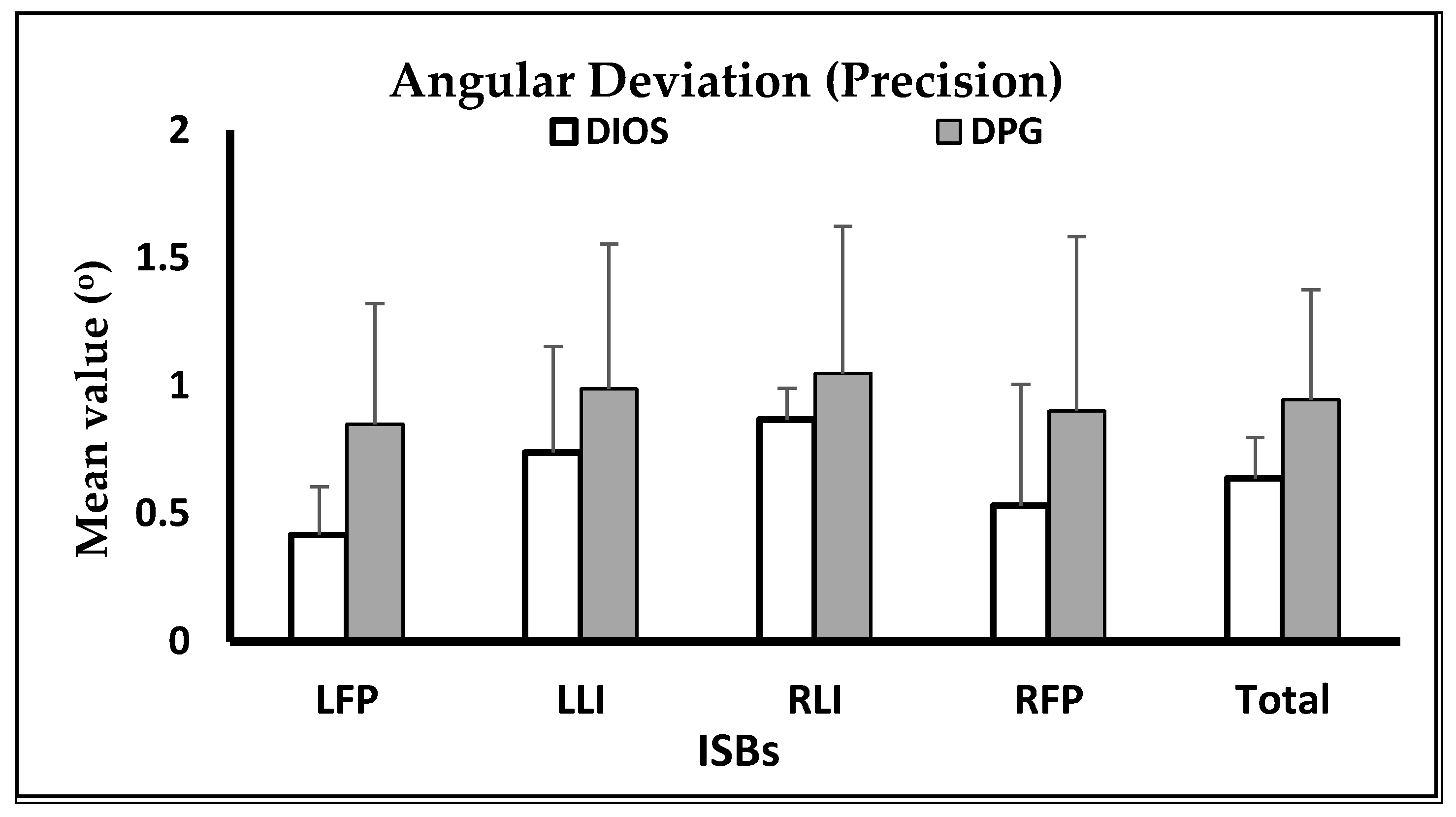
Angular Deviation for Trueness (Mean ± SD) in Degrees (°)
ISBsDIOS (n = 15)DPG (n = 15)p Value
LFP1.682 ± 0.205 b0.586 ± 0.088 a<0.001
LLI1.907 ± 0.234 c0.346 ± 0.038 a<0.001
RLI1.496 ± 0.1421.293 ± 0.0680.398
RFP1.890 ± 0.293 b0.672 ± 0.081 a<0.001
Global1.744 ± 0.175 b0.724 ± 0.064 a<0.001
p value<0.001<0.001
RLI < LFP < LLI = RFPLLI < LFP < RFP < RLI
a–c different letters indicate the presence of significant difference between impression techniques using post hoc tests. ISBs, intraoral scan-bodies; LFP, left first premolar; LLI, left lateral incisor; RLI, right lateral incisor; RFP, right first premolar; DIOS, digital intraoral scanning; DPG, digital photogrammetry.
Table 2. Means and standards deviations of RMS 3D distortions among implant level impression techniques in terms of precision.
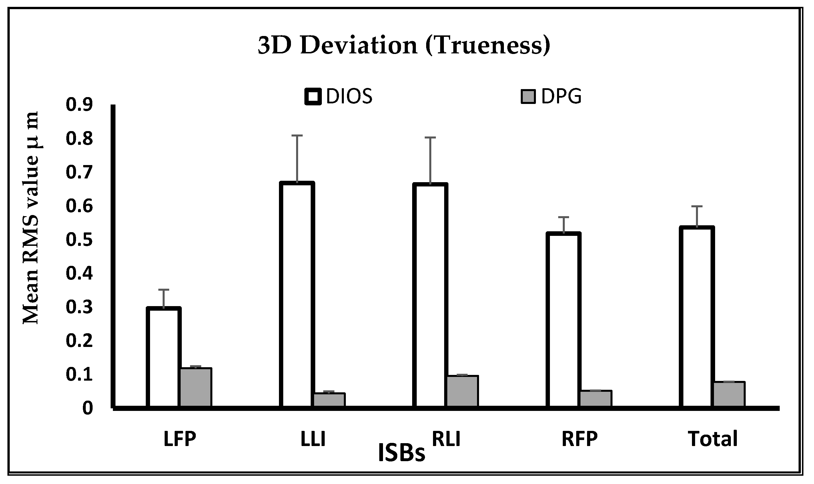
RMS 3D ISBs Deviation for Precision (Mean ± SD)
ISBsDIOS (n = 15)DPG (n = 15)p Value
LFP0.042 ± 0.020 a0.019 ± 0.015 a<0.001
LLI0.042 ± 0.016 a0.020 ± 0.021 a<0.001
RLI0.032 ± 0.007 a0.009 ± 0.007 a<0.001
RFP0.043 ± 0.012 b0.010 ± 0.014 a<0.001
Global0.039 ± 0.009 b0.014 ± 0.013 a<0.001
p value0.6150.666
a,b different letters indicate the presence of significant difference between impression techniques using post hoc tests. RMS, root mean square; ISBs, intraoral scan-bodies; LFP, left first premolar; LLI, left lateral incisor; RLI, right lateral incisor; RFP, right first premolar; DIOS, digital intraoral scanning; DPG, digital photogrammetry.
Publisher’s Note: MDPI stays neutral with regard to jurisdictional claims in published maps and institutional affiliations.

