1. Introduction
Nowadays, digitalization is fundamentally and sustainably transforming the industrial world. The industrial production process is moving towards “Industry 4.0” [
1], which is characterized by introducing digital twins, the digital representations of the physical assets, processes, or systems [
2].
On one hand, digital twins could empower the whole product life cycle from machine design to development and optimization until maintenance with high flexibility and efficiency [
3]. On the other hand, the increasing amount of digital twin data within different formats and from different resources creates a challenging context for human–machine interface (HMI) design [
4].
However, highly supportive HMIs used for operating machines and managing services are severely lacking. Comprehensive research is needed on how to refine the information, highlight relevant content, manage multiple access points and explore innovative interaction methods that simplify operations, enhance safety and correct decisions. This work, therefore, aims at exploring the possibility of creating an HMI for digital twin systems, specifically, leveraging the mixed reality technology to operate a digital twin based industrial crane.
1.1. Overview of Digital Twins
“A conceptual idea” of the digital twin was firstly proposed in early 2002 for product lifecycle management (PLM) [
5]. The concept contained three fundamental components: the virtual and physical space, as well as the constant information exchange between them. Through real-time data communication between the physical world and its digital counterpart, digital twins were expected to play a role through the life span of a product, i.e., development, growth, maintenance, and decline.
In 2010, the term “digital twin” was firstly adopted by NASA, where a digital twin was envisioned in its space vehicles as part of simulation-based system engineering [
6]. The digital twin was conceptualized to facilitate the probabilistic simulation of NASA’s aerospace vehicles, as well as the integration of real-time data from different sensors and historical data mainly for maintenance. The digital twin was also used to propose modifications in the mission profile, whereby it was argued to reduce the potential damage and improve the probability of the mission success.
The later years have witnessed the expansion of this term into an increasingly wide variety of domains and contexts with different applications and objectives [
2]. In some cases, digital twins were solely used for simulation and modeling of physical assets, systems or processes [
7,
8]. In other cases, they were also adopted for predictive maintenance or future design improvement by monitoring and evaluating e.g., the inefficiency or stress load of machinery [
9,
10].
A feature-based digital twin framework, proposed in [
11], included nine technical features and the integration of them through connection with the data link in the center. The nine features, i.e., computation, coupling, identifiers, security, data storage, user interfaces, simulation models, analysis, and artificial intelligence, marked the functional requirements in implementing digital twins in the context of Industry 4.0. Among those, a user interface defines show operators interact with the digital twin, thus functioning as a critical building component of any digital twin system.
1.2. HMIs in Industry 4.0
HMIs in the Industry 4.0 context should enable or at least function as a gateway for visualization, aggregation, and analysis of the rich data coming from different units within an industrial internet of things (IIoT) system [
12]. With a modern adapted production strategy applied in Industry 4.0, while the systems and processes are organized autonomously, the machine users are expected to perceive the information that is aggregated, prepared, and well presented by HMIs to monitor and, if necessary, give intervention to the processes by manipulating the physical components through HMIs. To empower this, various types of mobile devices have started to be adopted in manufacturing and production, such as overhead displays, tablets, and smartphones, with multi-modal (gesture, voice, position) or multi-touch interaction capabilities.
Among many HMI technologies, mixed reality (MR) is acknowledged as the forthcoming evolution in the interactions among humans, computers and the environment [
13]. Characterized by combining both augmented reality (AR) and virtual reality (VR) environments in the the reality–virtuality continuum [
14], MR technologies offer new opportunities for developing a hybrid reality with digital content embedded in the real world, and are therefore expected to bring a disruptive transformation particularly to the manufacturing and production industry.
1.3. Industrial MR/AR Applications
Industry 4.0 has already been witnessing plenty of applications of MR/AR, such as 3D visualization of a product, guidance on complicated assembly tasks, assistance of machine/process maintenance and of hands-on safety trainings. The vacuum-pump manufacturer, Leybold, developed an AR app for both the HoloLens and iPad platform and leveraged it in the in-house sales activities and customer support process [
15]. With the app, users could view and explore the information on the structure and different components of a vacuum pump, with no additional steps of disassemblies. An “augmented smart Factory” app was proposed in [
12], through which operators could interact with a cyber-physical system. The app could visualize the critical information of the system into virtual objects and superimpose them directly into the real-world scene surrounding the user.
However, most of the industrial MR/AR solutions only involved static information visualization or one-directional data flow from machinery systems to the interface, without enabling users to control or intervene in the physical processes or systems through MR/AR. Along with this research gap, a standardized procedure of quantitatively evaluating the control accuracy with MR/AR application was also not in place.
1.4. Crane HMI Solutions
This work selected an industrial overhead crane platform with its digital twin as a case study. Several crane HMI solutions have been presented in previous research works. A conceptual architecture of a speech-based HMI equipped with AR technology and interactive systems was proposed in [
16] for controlling mobile cranes. The use of AR and wearable technologies was also tested for industrial maintenance work in the crane industry to facilitate knowledge sharing among maintenance technicians in their everyday work [
17]. An approach integrating 4D building information modeling and AR, proposed in [
18], provided users with real-time navigation for tower crane lifting operation with enhanced safety and efficiency. An assistance system for mobile cranes leveraging AR was developed in [
19] to provide safety-related information for the crane operator. However, as addressed in the section above, those solutions were limited to one-directional data flow between the crane and the AR interface. In other words, AR was only used to improve data visualization, without involving any interactive component, through which users could directly control the crane.
The industrial crane platform in our research environment contained various practical components of a digital twin [
20], including two HMI solutions, a web-based interface [
21] and a HoloLens-based MR app [
22]. Both of them enabled users to monitor and control the crane movement. The web app was empowered by the advanced connectivity solution leveraging a GraphQL wrapper, which served as an additional interface between the crane OPC UA server and the client application, thus easing the cross-platform project development and ensuring scalability. However, the web app only emulated a basic control and monitor panel without additional features to enable an immersive or intuitive user experience. On the other hand, the HoloLens app brought the user experience to another immersive level, while its communication solution that relied on the WebSocket to access the crane OPC UA server was obsolete. Furthermore, only if users started the application every time at a specific location could the holograms be placed in a correct manner.
The limited mobility issue indicates a major challenge in MR, spatial registration and tracking of the MR environment, which ensure the alignment between the physical and virtual world. Registration determines the static offsets between the coordinate systems of markers, sensors and other objects, while tracking enables continuous detection of the object position and orientation in relation to a certain coordinate system in a real-time manner [
23]. Spatial Relationship Graphs (SRGs), representing directed cyclic graphs, can be adopted to specify the static and dynamic spatial properties of real or virtual objects and thus depict a high-level infrastructure of the registration and tracking environment [
24].
1.5. Contribution of This Work
The review of previous research works shows a clear research gap: MR control applications for industrial cranes were scarcely implemented, and therefore a method of evaluating the control accuracy, and the functionalities supporting control, such as registration of an MR environment and bi-directional data communication between an MR interface and a physical system, were also understudied.
This paper was built upon the master thesis of the first author [
25]. The thesis prototyped a proof-of-concept MR crane application, integrating different functional modules into one coherent interface. The application was featured by:
Interactivity: Real-time bi-directional interaction enabled by leveraging the most recently developed connectivity solution of the crane digital twin platform;
Flexibility: Improved mobility enabled by leveraging tracking and registration techniques;
Immersiveness: Immersive information visualization and interaction approach enabled by fully exploiting the MR technology.
The main contributions of the work, tackling the limitations of previous research on industrial MR/AR applications and existing crane HMI solutions, are:
2. Materials and Methods
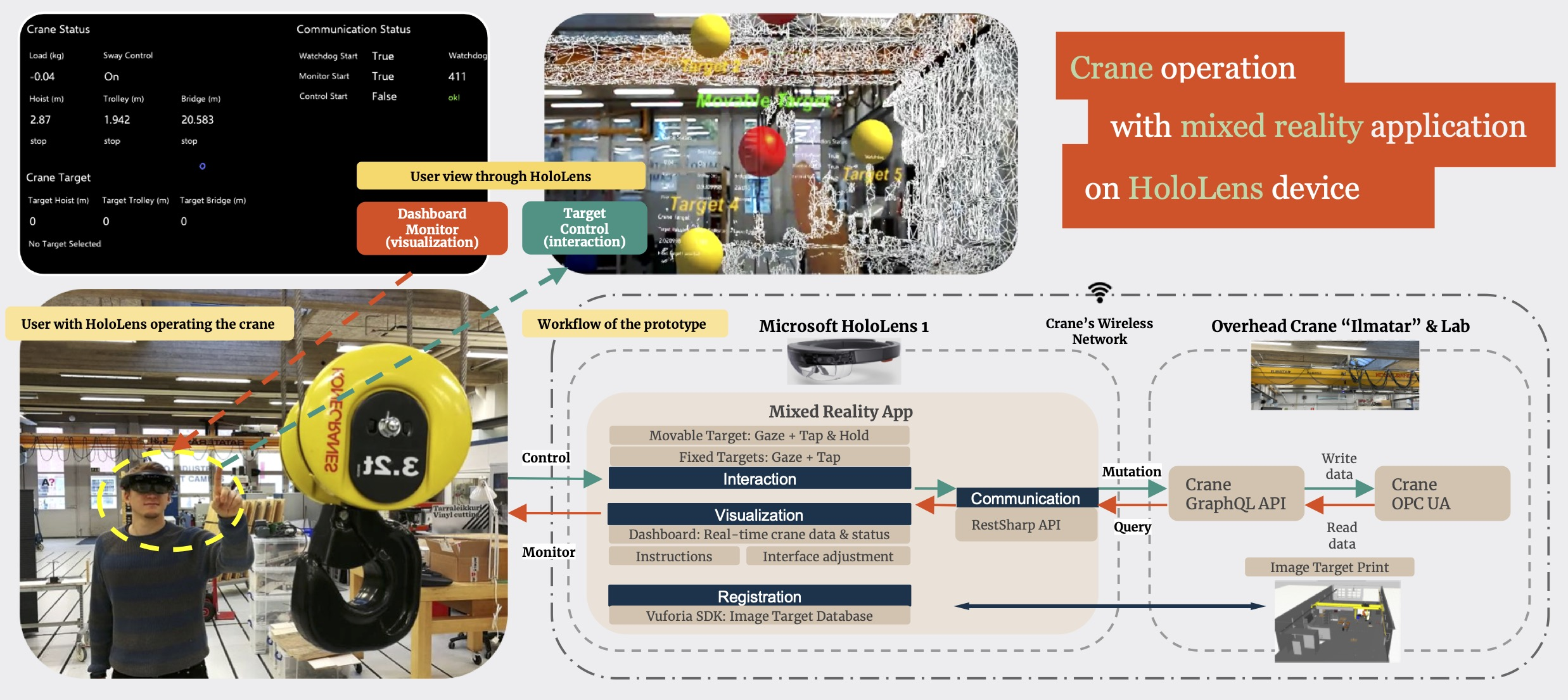
Figure 1 depicts the prototype architecture. The setup involved two pieces of hardware, Microsoft HoloLens 1 and the overhead crane “Ilmatar” with the lab. Accordingly, the software setup was divided into two parts, the one for mixed reality app development, and the software system of the crane platform.
2.1. Hardware Setup
2.1.1. Microsoft HoloLens (1st Generation)
The HoloLens 1, developed and manufactured by Microsoft, is the first head-mounted device running the Windows Mixed Reality (WMR) platform under the Windows 10 computer operating system [
26].
The see-through display of HoloLens 1 allows users to see digital content overlaid onto the surroundings in the real world. A variety of sensors enable the device to perceive its surroundings, place holograms in the real environment, and understand user inputs. The 2–3 h active battery life is a disadvantage for industrial use cases, but it can be compensated by the feature of fully functioning while charging. Additionally, HoloLens 1 is equipped with various networking technologies, among which Wi-Fi 802.11ac was employed in the work.
HoloLens 1 is capable of understanding users’ actions in three forms: gaze tracking, gesture input, and voice support. The head-gaze input allows users to navigate the cursor across the environments and focus on specific holograms. Then, users can perform actions on holograms either by gestures or voice input. Unlike HoloLens 2 that can recognize various gestures, HoloLens 1 only supports two simple gestures, bloom and air tap, and a composed gesture “tap and hold”. This work leveraged the head-gaze combined with air tap and “tap and hold” gestures for user interaction.
2.1.2. Digital Twin Based Overhead Crane “Ilmatar”
The industrial overhead crane “Ilmatar” was manufactured by the Finnish company Konecranes, and donated to the Aalto Industrial Internet Campus (AIIC) of Aalto University, functioning as a digital twin based IIoT platform for students and researchers to conduct experiments on Industry 4.0 related use cases [
27].
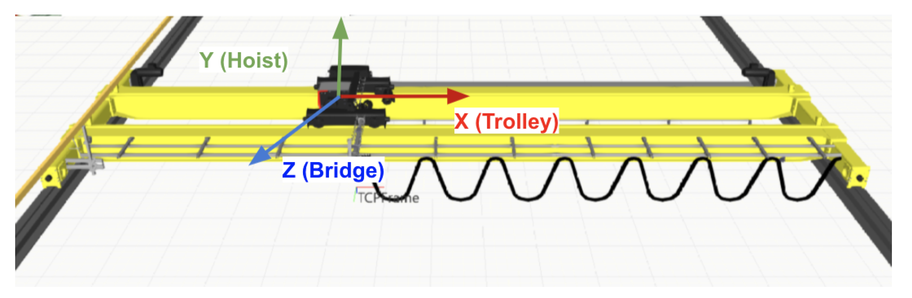
Figure 2 illustrates the three translationally moving components of the crane, namely hoist, trolley, and bridge, with moving ranges of 3, 9, and 20 m, respectively. These subsystems enable the crane to lift and move the load from one location to another. The coordinates added in the figure will be used in the later section to illustrate the specifications defined in the measurement protocol.
The crane is equipped with a manual controller. In this work, we used the controller to switch on the crane, manually move the crane in the pre-calibration and evaluation phase, as well as activate the external control, through which external clients can communicate with the crane via the OPC UA server (as elaborated in
Section 2.2.2). The external control is activated only when a corresponding button of the controller is constantly pressed, and deactivated once the button is released, whereby the controller also serves as a dead man’s switch.
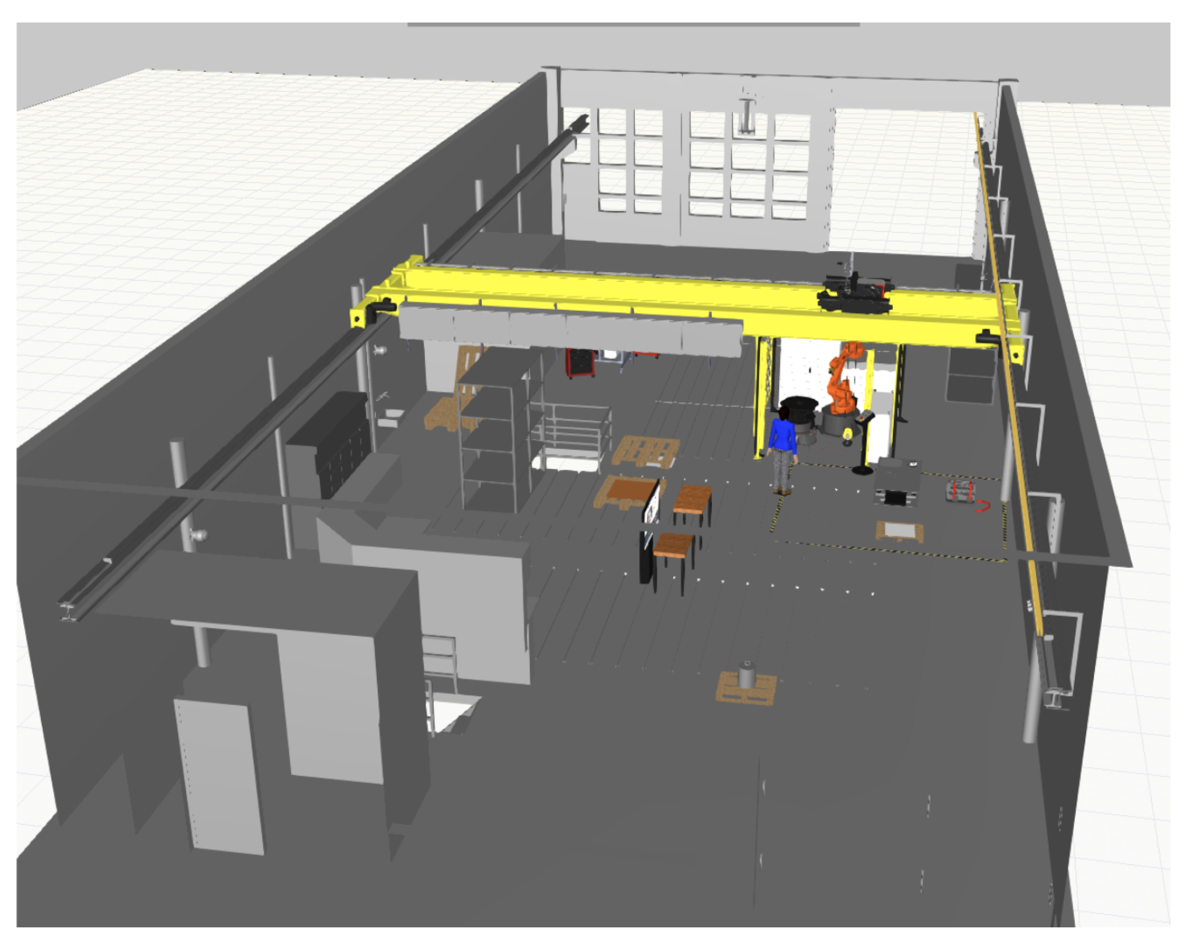
Figure 3 illustrates how the crane operational environment AIIC looks like through the screen capture of its 3D model that was created with the Visual Component software along with a thesis work [
28].
2.2. Software Setup
2.2.1. Software and SDKs for MR Development
We used several software tools and SDKs to facilitate certain application modules, namely visualization, interaction, registration, or communication, as well as support the overall development of the MR application.
Unity: a cross-platform game development engine, which is used to develop 3D VR, AR, MR, games, apps, and other experiences. In this work, it functioned as the main platform for MR application development.
Microsoft Mixed Reality Toolkit (MRTK): an SDK that provides APIs to employ different capabilities of the HoloLens for spatial coordination and input interfaces [
29]. In this work, it was used to facilitate the MR input system and create interactive components in the interaction and visualization modules of the application.
PTC Vuforia SDK: an SDK that uses computer vision technology to recognize and track planar images or 3D objects in real time [
30]. The image registration capability enables the application to position and orient virtual objects in relation to real-world objects when they are viewed through the HoloLens display [
31]. In this work, it was employed in the registration module to register the space and track the device.
RestSharp API: a comprehensive HTTP client library that enables interfacing with public APIs and accessing data quickly [
32]. In this work, it was used in the communication module to send the HTTP request to the GraphQL wrapper.
2.2.2. Software System and Connectivity of the Crane
The software specifications of the crane platform were elaborated in [
11,
20,
27], among which the following three parts presented direct relevance to this work.
OPC UA interface and data access: The crane interface leverages the OPC UA server for communication, which has multiple variables available for writing and reading, such as control variables for manual and target control, as well as status variables for radio selection and machinery of different subsystems [
33]. To control the crane through external clients, users need to be identified with an access code and then modify the value of the watchdog parameter constantly, with the dead man’s switch (see
Section 2.1.2) in its “off” position by continued pressure from the user’s hand.
GraphQL wrapper [
21]: The GraphQL wrapper functions as a broker between the client and the OPC UA server. The wrapper translates GraphQL queries from clients into OPC UA service requests and passes them forward to the OPC UA server. The response is also transformed into a GraphQL response.
Crane connectivity: With the current connectivity solution of the crane, the external client (in this work, HoloLens) is able to assess the crane GraphQL API and the OPC UA server by connecting to the crane network via Wi-Fi.
2.3. Mixed Reality Application for the Overhead Crane
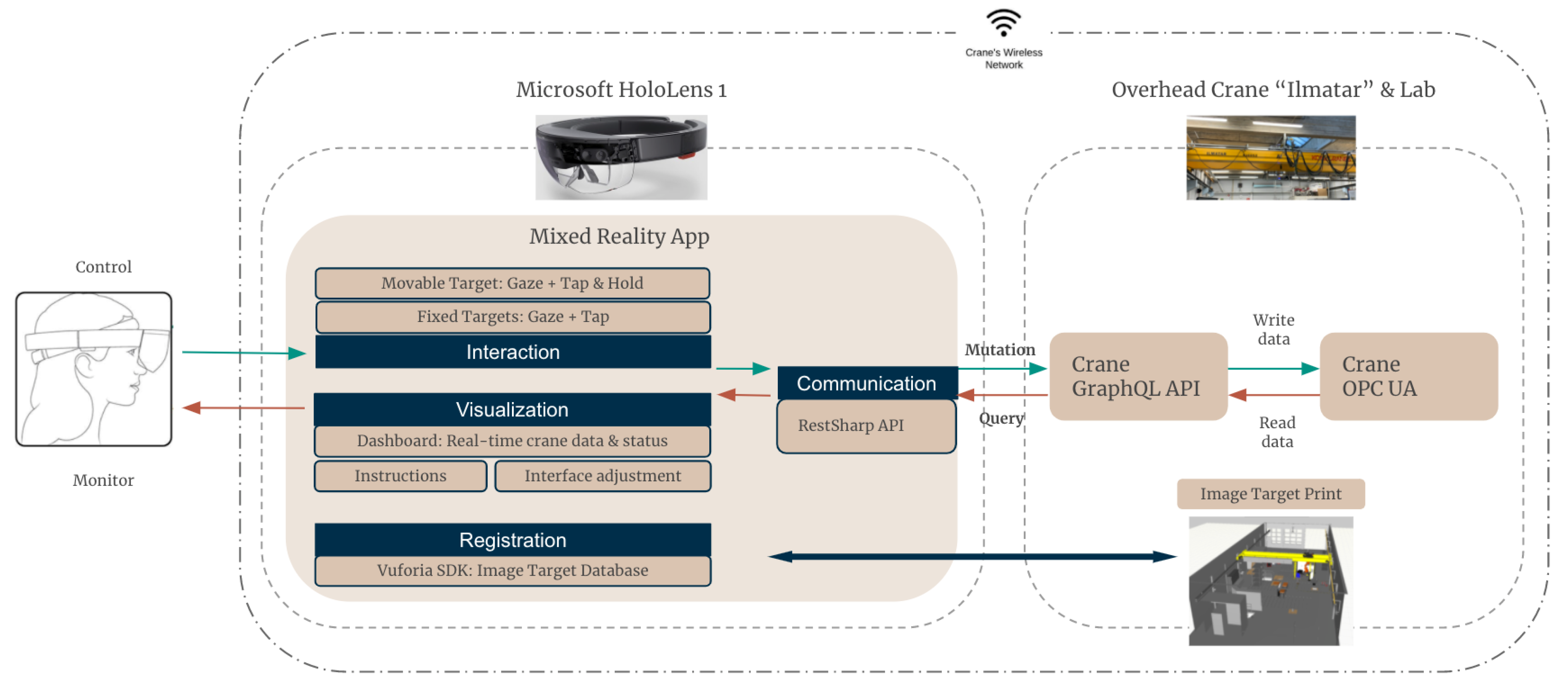
Figure 1 illustrates the bi-directional workflow based on the modularized architecture of the application. On one hand, the user could control the crane through the interaction module by either fixed target control or movable target control. On the other hand, the user could view the instructions on how to use the application, change the interface, and monitor the crane status through the visualization module. The registration module registered the virtual content with the physical lab environment based on an
image target database embedded in the application and the physical
image target print at the AIIC lab. The communication module, leveraging RestSharp API, enabled the application to send HTTP requests in the form of mutation or query to the crane GraphQL wrapper, which led to writing or reading data into the crane OPC UA, respectively. The connectivity between the MR application and the crane was enabled by the crane wireless network.
2.3.1. Interaction Module
The interaction module enabled crane control through interacting with virtual balls in the scene. There were two ways available for interaction, namely the movable target control and the fixed target control. The main difference between the two was whether the assigned crane target position was hooked to space or not.
Workflow of Fixed Target Control
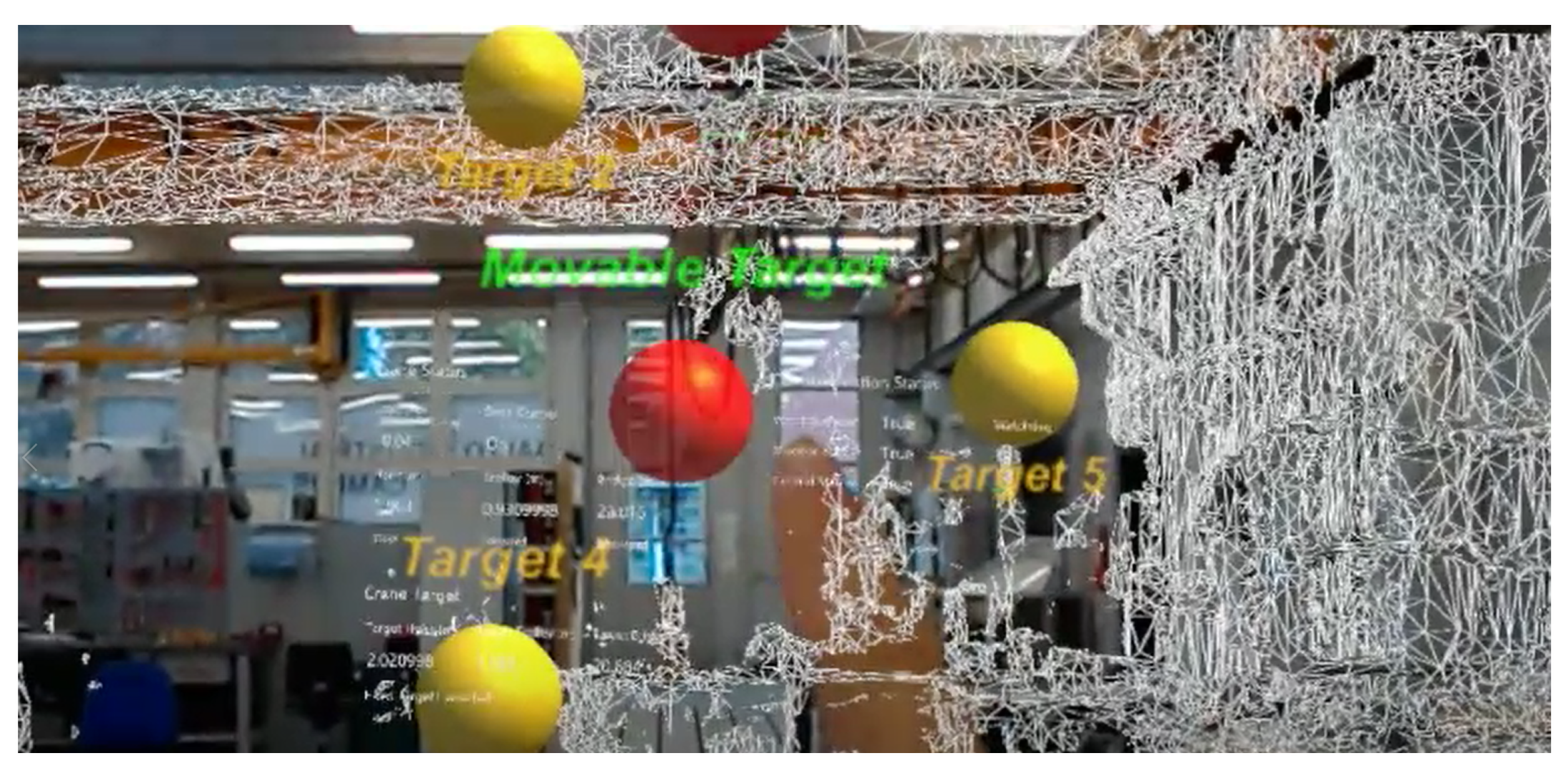
In the fixed target control mode, there were five fixed targets, which were displayed as five yellow 3D sphere-shaped holograms of 20-cm-diameter size, with the text “Target 1/2/3/4/5” on top of them, spreading around at the lab space. Users could select any of them by using the head gaze combined with an air-tap gesture. Once a target was selected, its color turned from yellow to red as an indicator of the successful commit. If meanwhile the control condition was fulfilled, the crane should move to the selected target position.
Workflow of Movable Target Control
The movable target control mode worked similarly, with the only difference that, instead of choosing from a range of the fixed targets, the user could drag and drop the movable target to freely define the target location. The movable target was presented as a 20-cm-diameter green 3D sphere, with the text “Movable Target” on top of it. Once the target was firstly selected with a gaze and “tap and hold” gesture inputs, the sphere color turned to red and the spatial mapping mesh showed up in the scene for enhancing users’ spatial awareness, then the user could navigate the sphere in the space while keeping the hold gesture. Once the user committed again with an air-tap gesture, the target was dropped and placed at a new location with its color turning blue and the spatial mapping mesh disappearing. If meanwhile the control condition was fulfilled, the crane would then start moving towards the target position.
Figure 4 shows the HoloLens view during movable target control.
Development of Interaction Module
Both interaction scenes were developed with the MRTK and its input system in Unity, which support the gaze as well as the “tap and hold” gesture inputs. When the MR application ran, one script constantly computed the value differences between the crane current position and the selected target position of each subsystem, namely the hoist, trolley, and bridge. The crane trolley and bridge first moved forward/backward until the differences were under a pre-defined threshold. Considering the operational safety, only once the trolley and bridge completed their movements did the hoist start to move up/down until the crane finally arrived at the target location in all three dimensions.
Regarding the parameters needed for the calculation above, the crane current position directly fetched through communication with the GraphQL server, while the selected target position was determined by the transformation of the position from Unity scene coordinates to the crane coordinates. The parameters in the transformation required a pre-calibration process as follows. We first manually controlled the crane to align its hook to each of the fixed targets, then read the crane positions from the crane GraphQL server (eventually from crane OPC UA) as well as the hologram position of the fixed targets from the Unity scene. Based on these, we calculated the linear relation between the positions under the crane system in the physical world and the ones in the Unity scene. The final scale and offset of this relation were determined by taking the average of the calculations over the five target sets. The calculated linear relation was then used to transform the target positions in Unity to determine the actual target positions that should be written into the crane system.
2.3.2. Visualization Module
The visualization module enabled users to directly monitor the crane real-time status through a dashboard, view the instructions on how to use the application, as well as adjust the interface (MR scene) in the way that they preferred by switching on/off the toggle of certain hologram.
Workflow of Dashboard
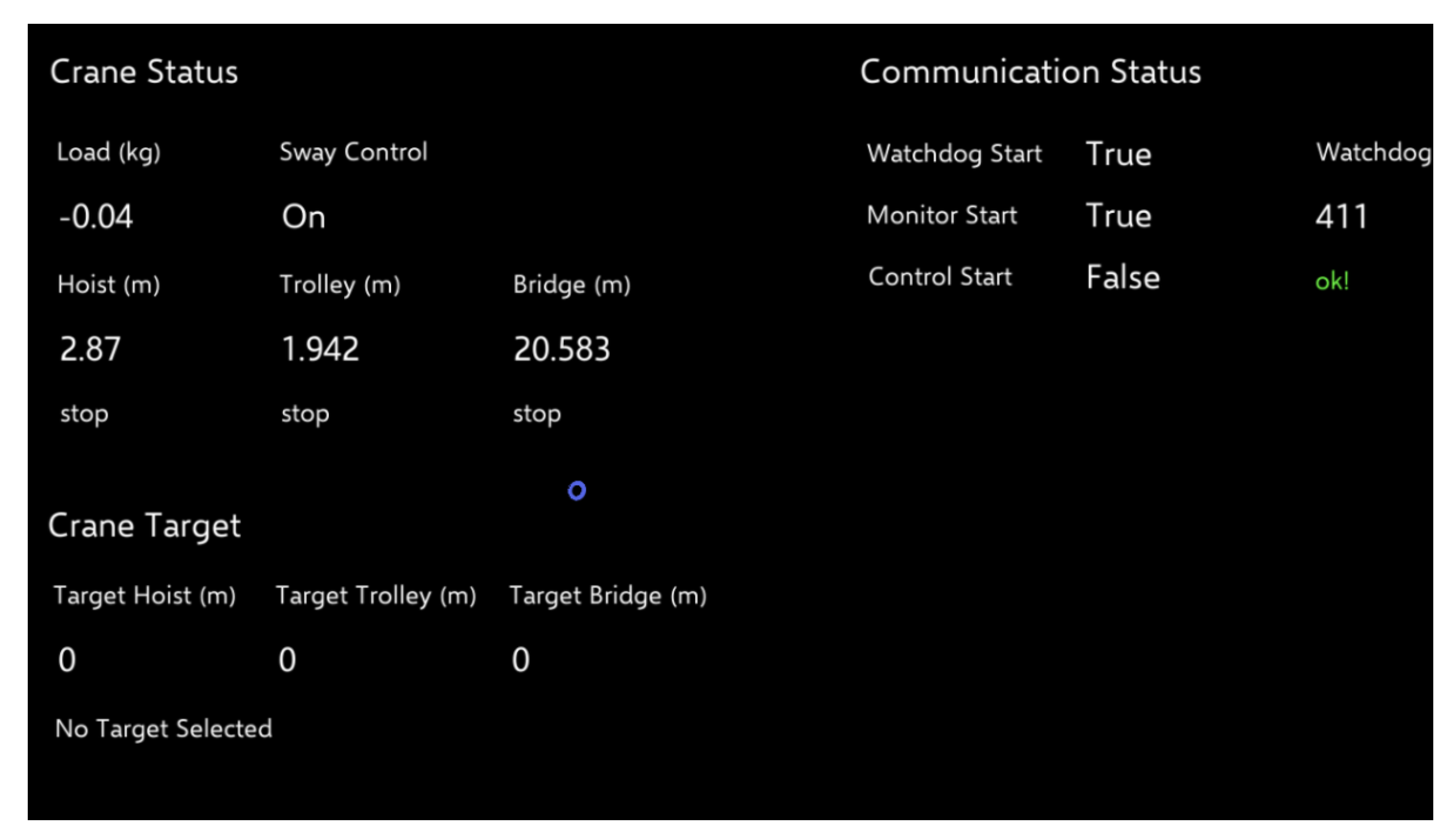
Figure 5 illustrates the dashboard with the crane real-time status data, which was grouped into three sections.
“Crane Status”, which included load value, sway control feature (on/off), positions and movements of the three subsystems (for trolley and bridge: stop/forward/backward, for hoist: stop/up/down). The data were fetched from the GraphQL server.
“Crane Target”, which displayed the name of the selected target (fixed target 1/2/3/4/5 or movable target) and the target position of three dimensions. The data were fetched by reading the corresponding parameters in the scripts attached to the Game Objects of fixed and movable targets that were selected.
“Communication Status”, which showed if the behaviors of the watchdog, monitor and control running in three different threads started, as well as displayed the updated value and status of the watchdog. The data was fetched from the communication script.
In the Unity project, the dashboard as a Game Object was placed under the “HoloLens Camera” hierarchy, meaning that the dashboard would always be displayed right in front of users’ view at a fixed distance. This way, users could check the information easily wherever they were moving towards or looking at.
Workflow of Instructions
In order to help new users to start, the application was empowered with interactive instructions. When users started the application, the welcome page came first, followed by detailed information on how to register the space. After users confirmed the completion of the registration step, the main hologram components appeared in the scene, including the fixed and movable targets, dashboard, and scene-switch toggles. The next page then introduced what the those new holograms were and where they were located. From this page, users could select the “quick guide”, which consisted of three pages showing what users could do with the application (i.e., to monitor and control the crane, adjust the scene, as well revise the guide). Users could also choose to skip the guide and directly start crane operation.
Workflow of Interface Adjustment
During the instruction phase, several holograms appeared and stayed in the scene, which provided users with components to interact with and information to view. However, certain information and components could be redundant for the crane operation at times, and their visibility would even potentially affect user experience.
For this reason, we introduced the interface adjustment to this prototype. With scene-switch toggles, users could switch off certain hologram components (i.e., dashboard, movable and fixed targets) in the default scene to clear up the view, and enable them again any time later. Additionally, the three pages of “quick guide” could be displayed again whenever users needed a recall on how to use the application.
Development of Visualization Module
The components in the visualization module were created with prefab UI building blocks from MRTK to make them visually appealing and operationally interactive. Those building blocks, such as the collision-based buttons and toggles, were configured to have audio-visual feedback for various types of inputs.
2.3.3. Registration Module
The registration module placed the holograms at the designed positions in the physical environment regardless of the user’s initial location. This way, users would not necessarily start the application from a certain place at the lab, thus benefiting from enhanced mobility and flexibility.
Workflow of Registration Procedure
The second page of instructions guided users to complete the registration step. In this step, users were instructed to walk towards and look closely at the image target print at the lab wall, until a green bounding box appeared and stably aligned to the image target. The holograms of the fixed and movable targets as well as the interface adjustment toggles then appeared at the designed locations, which would stay even when users moved their gaze away from the image target.
Development of Registration Module
The registration module was built with the Vuforia AR SDK in Unity, leveraging its features of image target, device tracking, and extended tracking. Firstly, we imported the
image target database processed by Vuforia as well as the spatial mapping mesh of the lab scanned by HoloLens camera into the Unity project. In addition, we placed a bounding box hologram around the
image target, which served as an indicator to help users understand if they completed the registration step successfully.
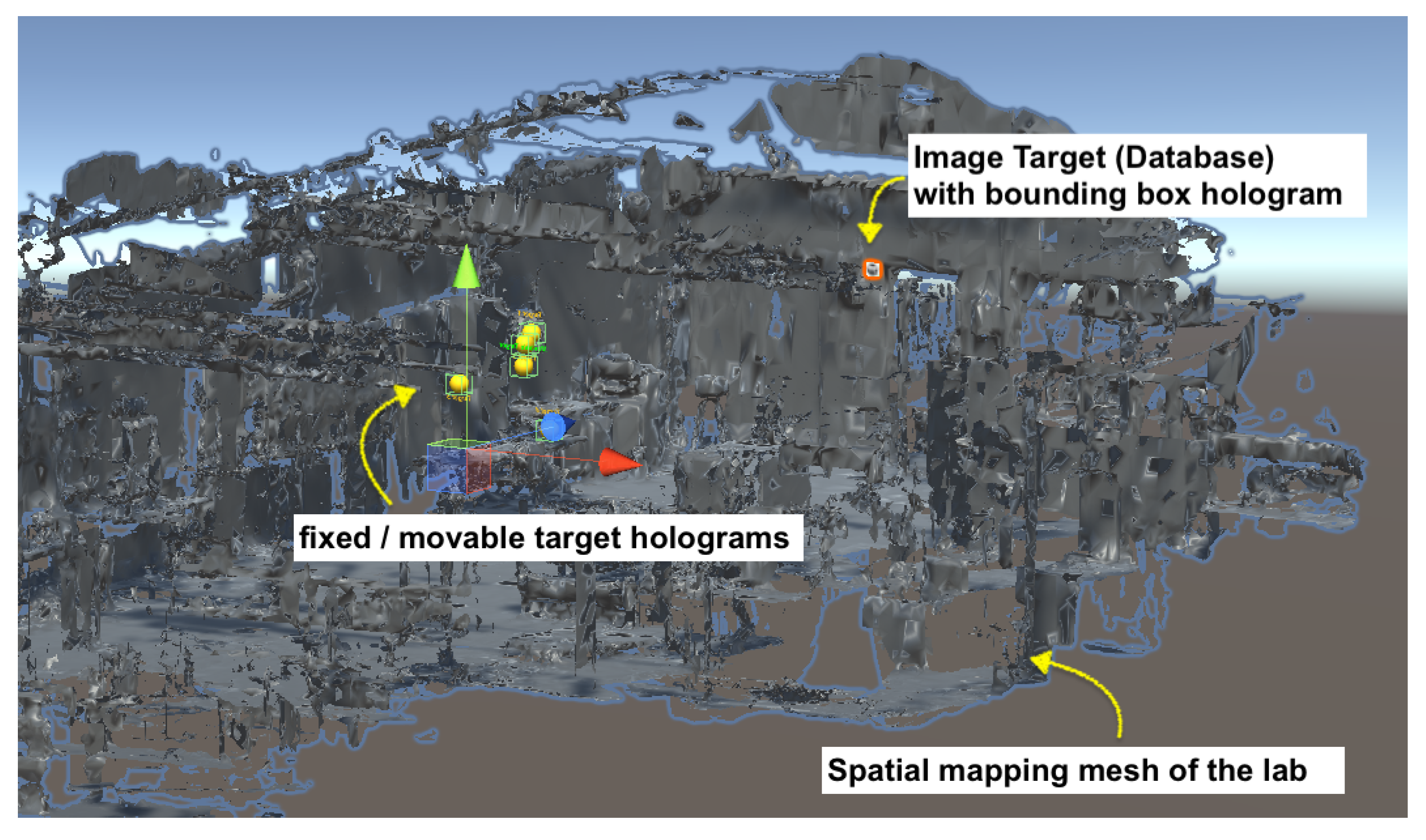
Figure 6 shows the spatial mapping mesh, holograms and
image target in the Unity scene.
Meanwhile, we printed this image target without changing its scale and ensured that its size matched the database size configured in the Unity project. We then fixed the image target print to the lab next to the crane, while its corresponding database in the Unity project was placed with approximately the same pose (i.e., both position and orientation) relative to the spatial mapping mesh of the lab as the image target print relative to the physical lab environment. Finally, from the HoloLens view, we checked the alignment between the spatial mapping mesh and the surroundings in the physical world and fine-tuned the relative pose of the image target in the Unity project accordingly. The alignment was only required to be at an approximate level since the mesh only functioned as a spatial reference that facilitated the process of locating the holograms. Once the scene was constructed, the mesh was deactivated and eventually not included in the application deployed to the HoloLens.
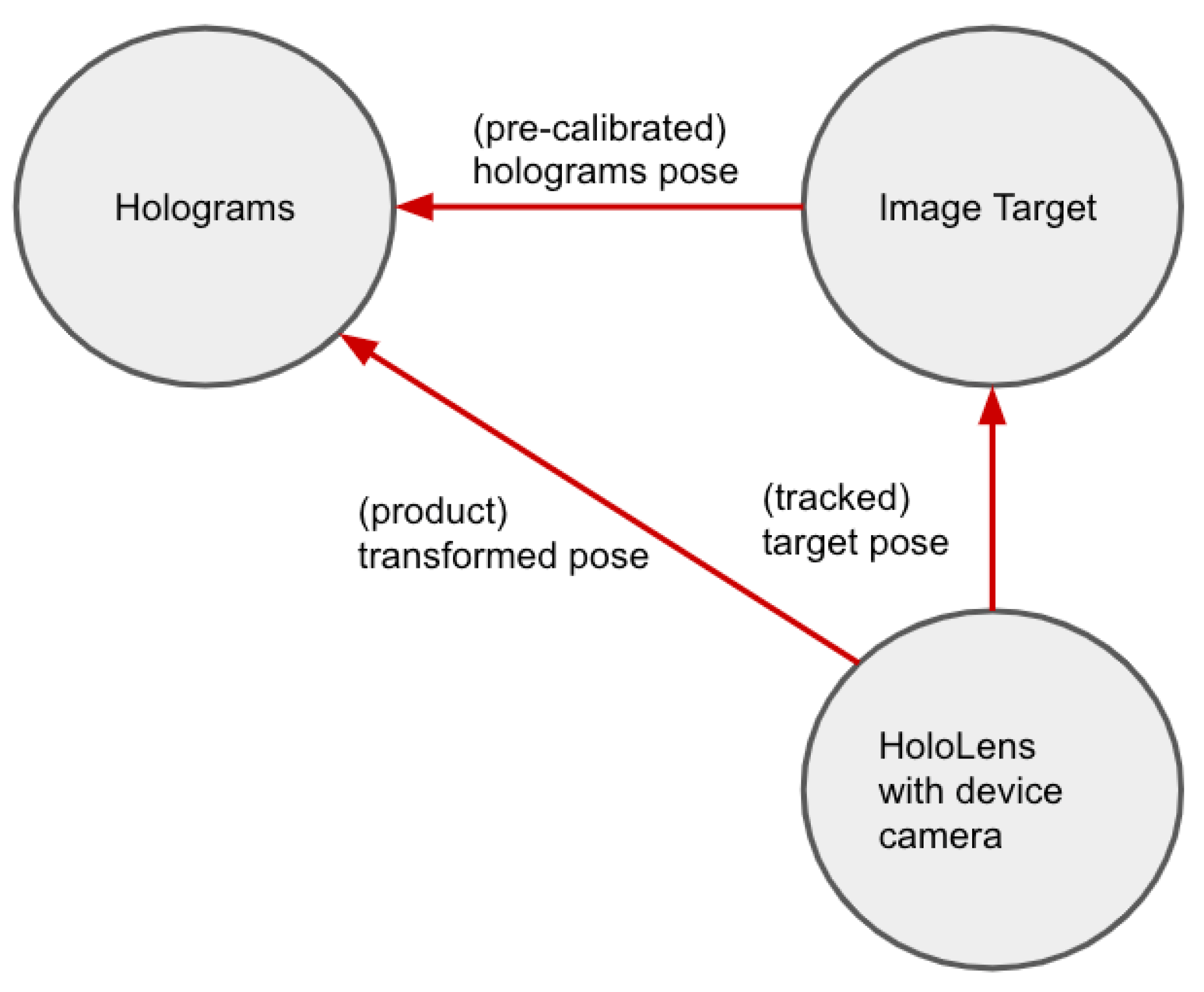
Figure 7 illustrates the spatial relationship in the registration setup. The HoloLens with the device camera functioned as a tracker that constantly accessed the pose of the
image target with Vuforia extended tracking feature. The poses of holograms were pre-calibrated with respect to the
image target. By concatenating the holograms pose relative to the
image target and the
image target pose relative to the HoloLens, the poses of the holograms with respect to the HoloLens device were derived.
2.3.4. Communication Module
The communication module functioned as a gateway between the crane and all the other modules of the application. We leveraged the RestSharp API in the Unity project to send HTTP requests (either a query request to read data, or a mutation request to write data) to the crane GraphQL wrapper. This way, the application could access the crane data, which would either be read and displayed in the dashboard of the visualization module or be written and modified by the fixed/movable target control of the interaction module.
Functional Components of Communication Module
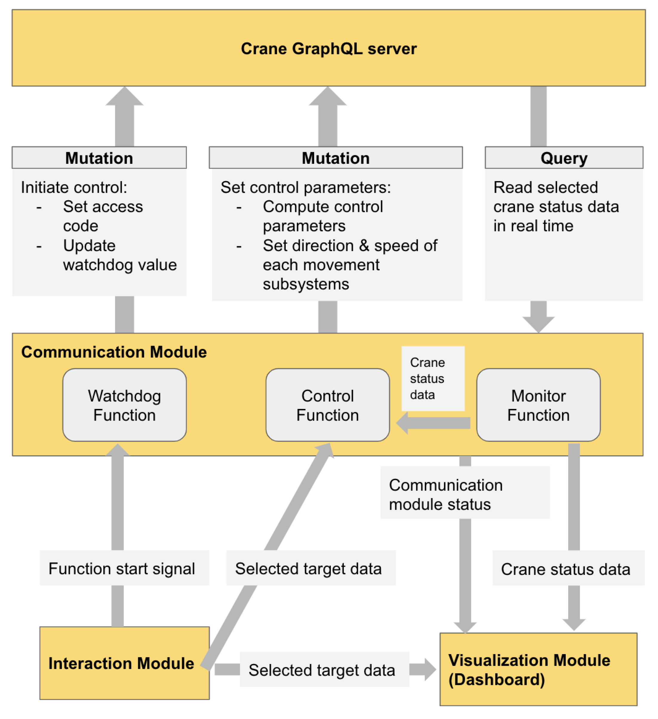
Figure 8 illustrates the three functional components in the communication module.
Watchdog function, which enabled the interaction module by setting the initial access code and updating the watchdog value constantly through mutation requests.
Monitor function, which enabled constant access to the selected crane real-time data, including all the crane status data displayed on the dashboard through query requests.
Control function, which enabled the interaction module by constantly modifying the movement speed and direction of each crane subsystem, based on the difference between the current location and the target location, through mutation requests.
Data Flow
Figure 8 also illustrates the data flow among the communication module, the other modules of the application, and the crane GraphQL server. Within the application, the interaction module gave the signal to call the watchdog function, and determined the target data flowing to the control function, while the visualization module received the crane status data flowing from the monitor function, the selected target data from the interaction module as well as the overall communication module status, then displayed them on the dashboard. Between the application and crane GraphQL server, both the watchdog function and the control function sent mutation requests, while the monitor function sent query requests to the server, which together enabled the application to exchange data with the crane in a bi-directional manner.
3. Results
To quantitatively evaluate the application performance in a standardized process, we defined a measurement protocol, following which we collected the actual crane position data during 20 measurements and the two selected target position data.
3.1. Control Accuracy Measurement Protocol
The measurement protocol divided the procedure into steps and defined each step with a fixed time allocation and operational specifications.
Table 1 illustrates the overall measurement procedure consisting of 20 repeated unit tests, each with registration as an initialization step, followed by unit measurements on two selected targets.
Table 2 illustrates the unit measurement procedure on a selected target. Each unit measurement included a sequence of switches on the view and moving direction, with a fixed time allocation. The X, Y, and Z in the table, as consistent with the notations in
Figure 2, represent the trolley, hoist, and bridge, respectively. The step-by-step protocol is as follows.
Setup of the HoloLens and crane: The tester first switches on the HoloLens and opens the crane MR application, then switches on the crane and activates its operation through the manual controller.
Registration of the holograms: Next, the tester stays close to the image target and looks at it until a green bounding box appears and stably aligns with the image target, which indicates that the registration step is completed.
Target selection and position record: Then, the tester selects Target 1 through air-tap on the corresponding hologram and records the target positions of the hoist, bridge, and trolley shown on the dashboard. The same works for Target 2. Since the target positions stay the same regardless of different registration setups, this step only needs to be done once for each selected target.
Moving the crane manually to the selected target: The tester navigates the crane with a manual controller to the selected target position, until the crane hook aligns with the target hologram, and then records the crane actual position. This step is an iterative process that requires observing from different views and fine-tuning in different moving directions. The protocol defines the time allocation as well as the sequence of the views and moving directions that the manual control procedure should follow (See
Table 2). For example, the tester first views from the XY-face, while moving the crane along the X direction for 10 s; Then, the view should be switched to a ZY-face while the crane is moved along the Z direction for another 10 s, and so on. The total duration of such a unit measurement sums up to 80 s. Once a unit measurement is done, the tester reads the crane status positions of the three subsystems from the application dashboard and records them. This step is repeated for both Targets 1 and 2.
Repeat the test: The tester conducts again Step 2 followed by Step 4 for both Target 1 and 2 as a unit test, and repeats the unit test 20 times (see
Table 1).
3.2. Measurement Implementation and Results
We implemented the measurements following the protocol above, and observed the following:
The holograms, including the bounding box around the image target and the selected targets, at times presented location shifting during the registration step or when manually moving the crane in a unit measurement.
It was complicated to ensure the holograms’ alignment with the objects from the physical world. The issues arose during the registration step between the bounding box and the image target, as well as when manually moving the crane between the target holograms and the crane hook.
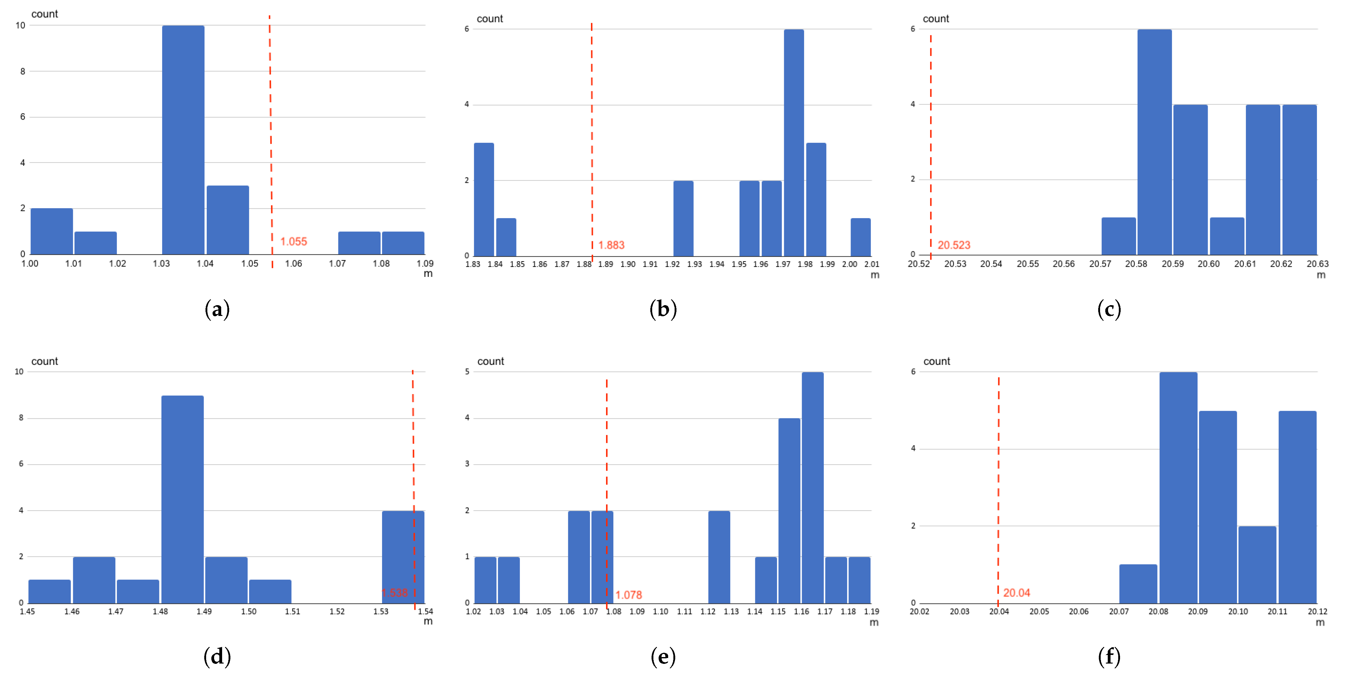
As a result, we collected the actual crane position data from 20 measurements and the target position data of the two selected targets. Each piece of position data consisted of three moving direction values. Based on this, we plotted the actual crane positions from the 20 measurements as histograms to show the data distribution (see
Figure 9). In this histogram, the
x-axis represented the positions in meter, and the
y-axis represented the occurrence count of positions within a certain range. As the reference, the selected target position was marked as a vertical dashed line in the same graph. The graph was generated for both Target 1 and 2, as well as for each moving subsystem, namely the hoist, bridge, and trolley. Each histogram with a reference line illustrates the differences between the target position and the actual positions. Among them, the target positions were static, while the actual positions in different unit measurements could vary.
4. Discussion
4.1. Control Accuracy
The measurement results suggest that the errors between the target and actual positions are within the range of 10 cm along any of the three moving directions, which are relatively small regarding the movement range of the crane, i.e., 3 m for the hoist, 9 m for the trolley, and 20 m for the bridge. Such a level of control accuracy is considered sufficient for the typical crane use cases of logistics purposes, where operators move the crane to fetch the load from and carry it to an approximate location. However, the current application would hardly serve the assembly tasks demanding precise control. For example, the crane use case of a heavy shrinking fit lift operation presented in [
34] would require high precision of under 0.5 mm.
The results also show a certain bias pattern in each dimension for both selected targets, which indicates that the control error could potentially be corrected by shifting the offset of the spatial transformation in the pre-calibration step. We interpreted the control errors as the gap between the pre-calibrated positions of the holograms and their actual locations in the physical space after the registration step. Stable and accurate registration and tracking of the image target cannot always be guaranteed with the current setup, resulting in spatial shifts of the holograms, which use the image target pose as a spatial transformation reference.
To improve the control accuracy, robust registration and tracking approaches can be applied in future work. For instance, instead of only one
image target, we can merge multiple planar markers with different poses, and benefit from enriched registration and tracking information, similarly as proposed in [
35,
36]. This way, the tracking error occurring in a certain dimension of the space could be compensated by more accurate tracking data of another marker. Furthermore, in case the device occasionally loses (extended) tracking of a certain marker, tracking data from other markers could still serve the purpose. This approach could therefore lead to reduced errors, increased effectiveness, and improved mobility. Other possible techniques, such as using the 3D model of the crane hook to register and track the physical hook, can also be considered in future work. Several 3D model-based AR use cases, as presented in [
37,
38,
39], have validated that the method could boost the efficiency and reliability of the registration and tracking performance.
4.2. Usability Research
The work has reached the proof-of-concept phase of exploring the technical feasibility of the industrial MR for digital twin based services. The research focus centered on the technical performance of the prototype, for which we conducted control accuracy measurements. On the other hand, one key design consideration of HMI in Industry 4.0 is to integrate users into the architecture of the cyber-physical systems [
12]. Users can be involved in every step of the HMI development loop, from conception to iterative prototyping until the final evaluation. We acknowledge the user study as a critical part for further HMI development, and consider accessing the usability of the interface via the system usability scale (SUS) [
40] and the workload via a NASA Task Load Index (NASA-TLX) [
41] in our future work, with similar approaches as presented in [
42,
43]. The SUS is a ten-item attitude Likert scale, focusing on the measurement of the three main aspects of usability: effectiveness, efficiency, and satisfaction. The NASA-TLX consists of six subjective sub-scales that address different aspects of the perceived workload. Usability research of such requires involving a number of users sufficient to obtain statistically significant outcomes and analyzing data using proper statistical tests.
4.3. Safety Features
Presenting a huge amount of data in a digital twin in an intuitive manner is challenging for HMI development especially when safety and situational awareness are essential [
4]. MR technologies allow users to interact with digital twin data at a new level through next-generation features and capabilities. At the same time, however, questions arise about how MR can affect system safety. The on-site overhead crane operation environment in this work is a safety-critical setting. The work has taken safety into consideration during the interface development. For instance, displaying a spatial mapping mesh of the surroundings when users navigate the movable target hologram could enhance spatial awareness and reduce the risk of placing the target in inaccessible locations. Other safety-related features, such as the color-changing visual feedback when users select any target, as well as the interface adjustment feature for changing holograms visibility and recalling the operation guide upon demand, have also been implemented in the work. Future research could incorporate more safety features in the MR interface, such as an operational area indicator and a user attention director with audio-visual effects. Furthermore, systematical evaluation could be conducted on how the adoption of MR technologies would impact the operator performance, decision processes, and situation awareness in the crane operating environment, following existing research frameworks like the one proposed in [
44].
In human-controlled systems, dead man’s switches have been widely employed as safety devices to ensure proper operation under life-threatening situations. In the context of crane operation, user incapacitation whilst driving the crane can lead to serious hazards for himself and co-workers in the same operational space. In this work, a dead man’s switch was in use, but it was embedded in a large manual controller (see
Section 2.1.2 and
Section 2.2.2), which mostly requires both hands to hold it. In the future, we could adopt a portable dead man’s switch only serving the safety purpose. To fit the MR operation practice, a dead man’s switch can ideally be a wearable button so that users could hold it down easily with one hand to keep the crane operable and leave the other hand for interacting with holograms while walking around.
4.4. Latency and Responsiveness
The interface was evaluated from the control accuracy angle, which, however, only covers the spatial performance. To integrate the temporal aspect into the loop and form a complete quantitative evaluation, future work could include measurements on the control latency, similarly as presented in [
45]. Note that the control latency in the context of this research can be interpreted in various ways. For instance, it can represent the end-to-end duration between the interaction action (e.g., selecting the target hologram) and the execution of the crane movement. Alternatively, it can also be measured by the time difference between the execution of the HTTP request from the MR application and the response (i.e., corresponding value change) from the GraphQL server or the crane OPC UA nodes. Different interpretations of control latency require different evaluation setups and methods to collect and process the data needed accordingly. Additionally, time-related plots of the control process, which illustrate the responsiveness of operating the crane with the MR application, could be included in future work.
5. Conclusions
Overall, this work presented and evaluated an MR interface for operating (i.e., controlling and monitoring) a digital twin based overhead crane. The MR application was developed for and running on the Microsoft HoloLens 1 device and the industrial crane platform “Ilmatar”. Various software and SDKs were employed, including those for MR development (i.e., Unity, MRTK, PTC Vuforia SDK, and RestSharp API), and the crane software system (i.e., the OPC UA interface, the GraphQL wrapper, and the crane connectivity solution). The application prototype consisted of the following four functional modules: the interaction module with the fixed and movable target control features for navigating the crane; the visualization module with the dashboard to monitor the crane status, the instructions for beginners, and the interface adjustment feature for changing holograms visibility; the registration module with spatial registration and tracking features for enhancing flexibility; as well as the communication module with real-time bi-directional data flow for enabling interactivity.
Furthermore, the work defined a protocol with a detailed procedure description and timestamps for measuring the accuracy of using MR application to control the crane. Accordingly, 20 measurements were implemented on the prototype in fixed target control mode, through which data were collected, and further analyzed and visualized. The results indicated that the errors between the target and actual positions are within the 10-cm range along all three moving directions, which are sufficiently small considering the overall moving range and the logistics use cases. Additionally, the work discussed the limitations and proposed future research directions addressing four aspects for improvement: the control accuracy, usability research, safety features, as well as latency and responsiveness.
Author Contributions
Conceptualization, X.T., J.A. and K.T.; methodology, X.T., J.A. and A.J; software, X.T.; resources, X.T., J.A. and K.T.; writing—original draft preparation, X.T.; writing—review and editing, X.T., J.A., A.J. and K.T.; visualization, X.T., J.A. and A.J.; supervision, K.T. and G.K.; project administration, X.T, J.A. and K.T.; funding acquisition, K.T. All authors have read and agreed to the published version of the manuscript.
Funding
This research was funded by Business Finland under Grant 3508/31/2019 and ITEA 3 Call 5 “MACHINAIDE”.
Institutional Review Board Statement
Not applicable.
Informed Consent Statement
Not applicable.
Data Availability Statement
Acknowledgments
The authors would like to thank all “MACHINAIDE” consortium members and those who presented or participated in discussions of this work.
Conflicts of Interest
The authors declare no conflict of interest.
Abbreviations
The following abbreviations are used in this manuscript:
| AIIC | Aalto Industrial Internet Campus |
| API | Application Program Interface |
| AR | Augmented Reality |
| GraphQL | Graph Query Language |
| HMI | Human–Machine Interface |
| IIoT | Industrial Internet of Things |
| MR | Mixed Reality |
| MRTK | Mixed Realty Toolkit |
| NASA-TLX | NASA Task Load Index |
| OPC UA | Open Platform Communications Unified Architecture |
| SDK | Software Development Kit |
| SRG | Spatial Relationship Graph |
| SUS | System Usability Scale |
| UI | User Interface |
| VR | Virtual Reality |
References
- Lasi, H.; Fettke, P.; Kemper, H.G.; Feld, T.; Hoffmann, M. Industry 4.0. Bus. Inf. Syst. Eng. 2014, 6, 239–242. [Google Scholar] [CrossRef]
- Negri, E.; Fumagalli, L.; Macchi, M. A review of the roles of digital twin in CPS-based production systems. Procedia Manuf. 2017, 11, 939–948. [Google Scholar] [CrossRef]
- El Saddik, A. Digital twins: The convergence of multimedia technologies. IEEE Multimed. 2018, 25, 87–92. [Google Scholar] [CrossRef]
- Zhu, Z.; Liu, C.; Xu, X. Visualisation of the digital twin data in manufacturing by using augmented reality. Procedia CIRP 2019, 81, 898–903. [Google Scholar] [CrossRef]
- Grieves, M. Digital twin: Manufacturing excellence through virtual factory replication. In White Paper; LLC: Melbourne, FL, USA, 2014; pp. 1–7. [Google Scholar]
- Shafto, M.; Conroy, M.; Doyle, R.; Glaessgen, E.; Kemp, C.; LeMoigne, J.; Wang, L. Modeling, Simulation, information Technology & Processing Roadmap—Technology Area 11. In National Aeronautics and Space Administration; NASA: Washington, DC, USA, 2010; p. 27. [Google Scholar]
- Reid, J.; Rhodes, D. Digital system models: An investigation of the non-technical challenges and research needs. In Proceedings of the Conference on Systems Engineering Research, Huntsville, AL, USA, 22–24 March 2016. [Google Scholar]
- Boschert, S.; Rosen, R. Digital twin—The simulation aspect. In Mechatronic Futures; Springer: Berlin/Heidelberg, Germany, 2016; pp. 59–74. [Google Scholar]
- Tao, F.; Cheng, J.; Qi, Q.; Meng, Z.; He, Z.; Sui, F. Digital twin-driven product design, manufacturing and service with big data. Int. J. Adv. Manuf. Technol. 2018, 94, 3563–3576. [Google Scholar] [CrossRef]
- Schroeder, G.N.; Steinmetz, C.; Pereira, C.E.; Espindola, D.B. Digital twin data modeling with automationml and a communication methodology for data exchange. IFAC-PapersOnLine 2016, 49, 12–17. [Google Scholar] [CrossRef]
- Autiosalo, J.; Vepsäläinen, J.; Viitala, R.; Tammi, K. A Feature-Based Framework for Structuring Industrial Digital Twins. IEEE Access 2020, 8, 1193–1208. [Google Scholar] [CrossRef]
- Gorecky, D.; Schmitt, M.; Loskyll, M.; Zühlke, D. human–machine-interaction in the industry 4.0 era. In Proceedings of the 2014 12th IEEE International Conference on Industrial Informatics (INDIN), Porto Alegre, Brazil, 27–30 July 2014; pp. 289–294. [Google Scholar]
- Speicher, M.; Hall, B.D.; Nebeling, M. What is Mixed Reality? In Proceedings of the 2019 CHI Conference on Human Factors in Computing Systems, Glasgow, UK, 4–9 May 2019; Association for Computing Machinery: New York, NY, USA, 2019; pp. 1–15. [Google Scholar] [CrossRef]
- Milgram, P.; Takemura, H.; Utsumi, A.; Kishino, F. Augmented reality: A class of displays on the reality-virtuality continuum. Telemanipulator Telepresence Technol. 1995, 2351, 282–292. [Google Scholar]
- Nichols, M.R. How Augmented Reality Will Disrupt The Manufacturing Industry. 2019. Available online: https://blog.thomasnet.com/augmented-reality-manufacturing (accessed on 1 April 2021).
- Majewski, M.; Kacalak, W. human–machine speech-based interfaces with augmented reality and interactive systems for controlling mobile cranes. In Proceedings of the International Conference on Interactive Collaborative Robotics, Budapest, Hungary, 24–26 August 2016; pp. 89–98. [Google Scholar]
- Aromaa, S.; Aaltonen, I.; Kaasinen, E.; Elo, J.; Parkkinen, I. Use of wearable and augmented reality technologies in industrial maintenance work. In Proceedings of the 20th International Academic Mindtrek Conference, Tampere, Finland, 17–18 October 2016; pp. 235–242. [Google Scholar]
- Lin, Z.; Petzold, F.; Hsieh, S. 4D-BIM Based Real Time Augmented Reality Navigation System for Tower Crane Operation. In Construction Research Congress 2020: Computer Applications; American Society of Civil Engineers: Reston, VA, USA, 2020; pp. 828–836. [Google Scholar]
- Quandt, M.; Beinke, T.; Freitag, M.; Kölsch, C. Requirements for an Augmented Reality-Based Assistance System. In Proceedings of the International Conference on Dynamics in Logistics, Bremen, Germany, 20–22 February 2018; pp. 335–340. [Google Scholar]
- Autiosalo, J.; Ala-Laurinaho, R.; Mattila, J.; Valtonen, M.; Peltoranta, V.; Tammi, K. Towards Integrated Digital Twins for Industrial Products: Case Study on an Overhead Crane. Appl. Sci. 2021, 11, 683. [Google Scholar] [CrossRef]
- Hietala, J.; Ala-laurinaho, R.; Autiosalo, J.; Laaki, H. GraphQL interface for OPC UA. In Proceedings of the 2020 IEEE Conference on Industrial Cyberphysical Systems (ICPS), Tampere, Finland, 10–12 June 2020; Volume 1, pp. 149–155. [Google Scholar] [CrossRef]
- Hublikar, P. A Prototype of a Digital Twin with Mixed Reality and Voice User Interfaces for Controlling a Smart Industrial Crane. Master’s Thesis, School of Science, Aalto University, Espoo, Finland, 2020. [Google Scholar]
- Keitler, P. Management of Tracking. Ph.D. Thesis, Technische Universität München, München, Germany, 2011. [Google Scholar]
- Pustka, D.; Huber, M.; Bauer, M.; Klinker, G. Spatial Relationship Patterns: Elements of Reusable Tracking and Calibration Systems. In Proceedings of the IEEE International Symposium on Mixed and Augmented Reality (IS- MAR’06), Santa Barbara, CA, USA, 22–25 October 2006. [Google Scholar]
- Tu, X. A Mixed Reality Interface for Digital Twin Based Crane. Master’s Thesis, School of Engineering, Aalto University, Espoo, Finland, 2020. [Google Scholar]
- Microsoft. HoloLens (1st gen) Hardware. 2019. Available online: https://docs.microsoft.com/en-us/hololens/hololens1-hardware (accessed on 1 April 2021).
- Autiosalo, J. Platform for industrial internet and digital twin focused education, research, and innovation: Ilmatar the overhead crane. In Proceedings of the 2018 IEEE 4th World Forum on Internet of Things (WF-IoT), Singapore, 5–8 February 2018; pp. 241–244. [Google Scholar] [CrossRef]
- Hannonen, J. Simulation and Visualization Model of an Overhead Crane. Master’s Thesis, School of Engineering, Aalto University, Espoo, Finland, 2020. [Google Scholar]
- Microsoft. What is the Mixed Reality Toolkit. 2019. Available online: https://docs.microsoft.com/en-gb/windows/mixed-reality/mrtk-unity/?view=mrtkunity-2021-01 (accessed on 12 May 2021).
- Vuforia. Vuforia Developer Library—Device Tracking Overview. 2020. Available online: https://library.vuforia.com/features/environments/device-tracker-overview.html (accessed on 12 May 2021).
- Vuforia. Vuforia Developer Library—Image Targets. 2020. Available online: https://library.vuforia.com/features/images/image-targets.html (accessed on 12 May 2021).
- RestSharp. RestSharp Homepage. 2021. Available online: https://restsharp.dev/ (accessed on 12 May 2021).
- Rantala, K.; Oy, J.T.K.G. Controlling of Lifting Device. U.S. Patent 10495880B2, 3 December 2019. Available online: https://patents.google.com/patent/US10495880B2/en?oq=US+10%2c495%2c880+B2 (accessed on 12 May 2021). [CrossRef]
- Sjöman, H.; Autiosalo, J.; Juhanko, J.; Kuosmanen, P.; Steinert, M. Using Low-Cost Sensors to Develop a High Precision Lifting Controller Device for an Overhead Crane—Insights and Hypotheses from Prototyping a Heavy Industrial Internet Project. Sensors 2018, 18, 3328. [Google Scholar] [CrossRef] [PubMed] [Green Version]
- Uematsu, Y.; Saito, H. AR registration by merging multiple planar markers at arbitrary positions and poses via projective space. In Proceedings of the 2005 International Conference on Augmented Tele-Existence, Christchurch, New Zealand, 5–8 December 2005; pp. 48–55. [Google Scholar]
- Yoon, J.H.; Park, J.S.; Kim, C. Increasing camera pose estimation accuracy using multiple markers. In Proceedings of the International Conference on Artificial Reality and Telexistence, Hangzhou, China, 29 November–1 December 2006; pp. 239–248. [Google Scholar]
- Behringer, R.; Park, J.; Sundareswaran, V. Model-based visual tracking for outdoor augmented reality applications. In Proceedings of the International Symposium on Mixed and Augmented Reality, Darmstadt, Germany, 30 September–1 October 2002; pp. 277–322. [Google Scholar]
- Reitmayr, G.; Drummond, T.W. Going out: Robust model-based tracking for outdoor augmented reality. In Proceedings of the 2006 IEEE/ACM International Symposium on Mixed and Augmented Reality, Santa Barbard, CA, USA, 22–25 October 2006; pp. 109–118. [Google Scholar]
- Pressigout, M.; Marchand, E. Hybrid tracking algorithms for planar and non-planar structures subject to illumination changes. In Proceedings of the 2006 IEEE/ACM International Symposium on Mixed and Augmented Reality, Santa Barbard, CA, USA, 22–25 October 2006; pp. 52–55. [Google Scholar]
- Brooke, J. SUS-A quick and dirty usability scale. Usability Eval. Ind. 1996, 189, 4–7. [Google Scholar]
- Hart, S.G. NASA-task load index (NASA-TLX); 20 years later. In Proceedings of the Human Factors and Ergonomics Society Annual Meeting, San Francisco, CA, USA, 16–20 October 2006; Sage Publications: Los Angeles, CA, USA, 2006; Volume 50, pp. 904–908. [Google Scholar]
- Wang, P.; Bai, X.; Billinghurst, M.; Zhang, S.; Wei, S.; Xu, G.; He, W.; Zhang, X.; Zhang, J. 3DGAM: Using 3D gesture and CAD models for training on mixed reality remote collaboration. Multimed. Tools Appl. 2021, 80, 31059–31084. [Google Scholar] [CrossRef]
- Pouliquen-Lardy, L.; Milleville-Pennel, I.; Guillaume, F.; Mars, F. Remote collaboration in virtual reality: Asymmetrical effects of task distribution on spatial processing and mental workload. Virtual Real. 2016, 20, 213–220. [Google Scholar] [CrossRef]
- Grabowski, M.; Rowen, A.; Rancy, J.P. Evaluation of wearable immersive augmented reality technology in safety-critical systems. Saf. Sci. 2018, 103, 23–32. [Google Scholar] [CrossRef]
- Sielhorst, T.; Sa, W.; Khamene, A.; Sauer, F.; Navab, N. Measurement of absolute latency for video see through augmented reality. In Proceedings of the 2007 6th IEEE and ACM International Symposium on Mixed and Augmented Reality, Nara, Japan, 13–16 November 2007; pp. 215–220. [Google Scholar] [CrossRef]
Figure 1.
Setup, architecture and workflow of the prototype: The prototype consisted of two parts, namely the mixed reality application running on HoloLens 1 device, and the overhead crane and the lab with its software system; Within the MR application, functionalities were grouped into four modules, namely interaction, visualization, registration and communication; Users wearing the HoloLens 1 device could interact with the crane in a bi-directional manner (i.e., controlling and monitoring) through the MR application under the crane wireless network.
Figure 2.
Components of the crane “Ilmatar” (a screen capture of its Visual Component model [
28]): Three subsystems enable translational movements in three dimensions—hoist for moving up and down, trolley and bridge for moving backward and forward.
Figure 2.
Components of the crane “Ilmatar” (a screen capture of its Visual Component model [
28]): Three subsystems enable translational movements in three dimensions—hoist for moving up and down, trolley and bridge for moving backward and forward.
Figure 3.
Layout of the lab AIIC environment with the crane inside (a screen capture of a Visual Component model [
28]).
Figure 3.
Layout of the lab AIIC environment with the crane inside (a screen capture of a Visual Component model [
28]).
Figure 4.
HoloLens view while the user was navigating the movable target: the spatial mapping mesh of the AIIC space captured by the HoloLens camera was also displayed in the scene, to enhance users’ spatial awareness and reduce the risk of placing the movable target in inaccessible locations.
Figure 4.
HoloLens view while the user was navigating the movable target: the spatial mapping mesh of the AIIC space captured by the HoloLens camera was also displayed in the scene, to enhance users’ spatial awareness and reduce the risk of placing the movable target in inaccessible locations.
Figure 5.
Screen capture of the dashboard from the Unity project in the play mode: the information displayed in the dashboard consisted of three sections, the “Crane Status”, “Crane Target” and “Communication Status”.
Figure 5.
Screen capture of the dashboard from the Unity project in the play mode: the information displayed in the dashboard consisted of three sections, the “Crane Status”, “Crane Target” and “Communication Status”.
Figure 6.
Spatial mapping mesh, holograms, and image target in the Unity scene: the pose of the mesh, the holograms of fixed/movable targets, and the bounding box were determined by the pose of the image target, with the mesh functioning as a spatial reference for the scene design.
Figure 6.
Spatial mapping mesh, holograms, and image target in the Unity scene: the pose of the mesh, the holograms of fixed/movable targets, and the bounding box were determined by the pose of the image target, with the mesh functioning as a spatial reference for the scene design.
Figure 7.
Spatial Relationship Graph (SRG) of the registration setup: we got the spatial transformation between holograms and the HoloLens device through their relations with the image target.
Figure 7.
Spatial Relationship Graph (SRG) of the registration setup: we got the spatial transformation between holograms and the HoloLens device through their relations with the image target.
Figure 8.
Functional components of the communication module and data flow: The interaction module set the execution of the watchdog function, which then sent mutation requests to the GraphQL server for setting the access code and updating the watchdog value constantly. On the other hand, the interaction module also provided the selected target data to the control function, which then computed the control parameter values and sent them as mutation requests. Meanwhile, the visualization module received constant updates of the crane status from the monitor function through its query requests from the server, the selected target data from the interaction module as well as the execution status of each function within the communication module.
Figure 9.
Histograms of 20 measurements: The histogram represents the actual crane position of each moving subsystem and for each of the two selected targets, which are marked in vertical dashed lines. (a) Target 1 measurement—Hoist (Y); (b) Target 1 measurement—Bridge (Z); (c) Target 1 measurement—Trolley (X); (d) Target 2 measurement—Hoist (Y); (e) Target 2 measurement—Bridge (Z); (f) Target 2 measurement—Trolley (X).
Table 1.
Protocol for the overall procedure: Unit tests were conducted 20 times, each consisting of initial registration and follow-up measurements on two selected targets.
Table 1.
Protocol for the overall procedure: Unit tests were conducted 20 times, each consisting of initial registration and follow-up measurements on two selected targets.
| Test | Procedure | Time Allocation |
|---|
| Test 1 | Registration | 20 s |
| | Target 1 measurement | 80 s |
| | Target 2 measurement | 80 s |
| Test 2 | Registration | 20 s |
| | Target 1 measurement | 80 s |
| | Target 2 measurement | 80 s |
| ... | repeat the unit test 20 times | ... |
| Test 20 | Registration | 20 s |
| Target 1 measurement | 80 s |
| Target 2 measurement | 80 s |
| Time sum | 60 min |
Table 2.
Protocol for the unit measurement: Measurements followed the pre-defined sequence of movements and measurement steps, with specifications on the view switch and moving direction, as well as the time allocation for each step.
Table 2.
Protocol for the unit measurement: Measurements followed the pre-defined sequence of movements and measurement steps, with specifications on the view switch and moving direction, as well as the time allocation for each step.
| View | Moving Direction | Time Allocation |
|---|
| XY | X | 10 s |
| ZY | Z | 10 s |
| XY | X | 5 s |
| ZY | Z | 5 s |
| XY | Y | 10 s |
| X | 5 s |
| Y | 5 s |
| X | 5 s |
| ZY | Z | 10 s |
| Y | 5 s |
| Z | 5 s |
| Y | 5 s |
| | Time sum | 80 s |
| Publisher’s Note: MDPI stays neutral with regard to jurisdictional claims in published maps and institutional affiliations. |
© 2021 by the authors. Licensee MDPI, Basel, Switzerland. This article is an open access article distributed under the terms and conditions of the Creative Commons Attribution (CC BY) license (https://creativecommons.org/licenses/by/4.0/).


