Article

Comparison of Marginal Integrity and Surface Roughness of Selective Laser Melting, CAD-CAM and Digital Light Processing Manufactured Co-Cr Alloy Copings

1
Department of Prosthetic Dental Science, College of Dentistry, King Saud University, Riyadh 11545, Saudi Arabia
2
Department of General Dentistry, College of Dentistry, King Saud University, Riyadh 11545, Saudi Arabia
*
Author to whom correspondence should be addressed.
Appl. Sci. 2021, 11(18), 8328; https://doi.org/10.3390/app11188328
Submission received: 28 July 2021 / Revised: 2 September 2021 / Accepted: 4 September 2021 / Published: 8 September 2021

Abstract

:
The purpose of the present study was to evaluate the influence of fabrication techniques on the surface micro-roughness (Ra) and marginal misfit of cobalt chromium (CoCr) copings. A mandibular first molar was prepared for a metal ceramic crown. Forty metal copings were prepared and divided into groups (n = 10). Group 1, Casting-Lost wax technique (Cast-LWT), Group 2, CAD-CAM, Group 3, Selective laser melting (SLM), and Group 4, Digital light processing-Cast (DLP-Cast). Ra was measured using laser profilometry and marginal misfit was analyzed with Micro-CT. Analysis of variance (ANOVA), Tukey multiple comparison, and correlation coefficient tests were applied (p < 0.05). SLM technique showed the highest Ra (2.251 ± 0.310 μm) and the Cast-LWT group presented the lowest Ra (1.055 ± 0.184 μm). CAD-CAM copings showed statistically lower Ra compared with SLM samples (p = 0.028), but comparable Ra to DLP-Cast (p > 0.05). CoCr copings fabricated from the DLP-Cast technique demonstrated the highest marginal misfit (147.746 ± 30.306 μm) and the lowest misfit was established by SLM copings (27.193 ± 8.519 μm). The SLM technique displayed lower marginal misfit than DLP-Cast and CAD-CAM (p = 0.001), but comparable misfit to Cast-LWT copings. Ra influenced the marginal misfit in CAD-CAM, SLM, and DLP-Cast technique-fabricated copings. (p < 0.01). Marginal misfit and Ra of CoCr copings are contingent on the different fabrication techniques.

1. Introduction

Porcelain-fused-to-metal (PFM) crowns have been widely used in dentistry as a fixed dental aesthetic replacement for decades [1]. Increased aesthetic demands, advancements in casting techniques, availability of different alloys, and their use in almost all clinical conditions account for the popularity of PFM crowns [2]. Precise marginal fit of dental cast restoration is considered as the most critical and technical feature for the long-term successful clinical outcomes. Available evidence advocates an acceptable range of marginal misfit of full veneer crowns to be 100 to 120 µm [3]. However, multiple studies suggest different ranges of acceptable marginal misfit (10 to 160 µm) [4]. Increased marginal discrepancy accounts for the 10% of prosthetic failures, i.e., exposure of dental cement to the oral environment, bacterial penetration and plaque retention, secondary carious lesions, negative pulp reactions, marginal discoloration, periodontal disturbances, and esthetic and functional compromise [3].
Primarily, marginal integrity of cast copings are influenced by the surface characteristics, cast adaptation, and luting adhesives used [5]. Similarly, surface micro-roughness (Ra) also influences the retention of indirect restoration [3]. It has been proposed that different fabrication techniques exhibit different Ra levels for cast indirect restorations. The casting with lost-wax technique (Cast-LWT) is commonly used to fabricate metal copings for PFM crowns [6,7]. The process involves the carving of inlay wax on a dye that mimics the anatomy and morphology of the lost tooth followed by spruing, investing, burnout, and casting with metal ingots [8]. However, it is time consuming and technique and operator sensitive to achieve a better quality of casting restoration [9]. In order to overcome these shortcomings, alternate contemporary digitally advanced fabrication techniques have been developed.
Among various techniques, computer-aided design/manufacturing (CAD-CAM) provides better standardization [10]. This method works on the principle of subtractive manufacturing, involving the milling of a solid metal block in to a desired shape of indirect prosthesis [11]. CAD-CAM offers standard-quality restorations, time efficiency, dimensional accuracy, and reduced risk of health hazards [12,13]. However, subtractive technique is associated with material wastage along with increased cost and difficult accessibility [14]. Current literature demonstrates conflicting outcomes related to the effect of Ra on the marginal misfit of metal copings fabricated using the subtractive technique [15,16].
Limitations related to the complexity of design obtained by subtractive technique led to introduction of novel additive fabrication techniques including selective laser melting (SLM), selective laser-sintering (SLS), and digital light processing (DLP) [17]. SLM is also referred to as 3D printing which is based on addition of material layer by layer using high power-density laser to melt and fuse non-precious alloy powders, particularly titanium and cobalt-chromium [18]. It can produce complex restoration designs without wasting a large amount of material. It is also able to produce multiple parts at the same time. However, it is an expensive technology and requires digital learning with operator skills [19]. Moreover, Digital light projection (DLP) is a further development in 3D Printing [20]. DLP printers project a silhouette of an entire layer simultaneously and polymerize it with a single shot of curing light with faster printing [21]. This method is rapid, precise, and affordable compared with the SLM technique along with providing a better finish [22]. However, data related to the influence of these fabrication methods on the Ra and misfit of metal copings need further investigation.
In a recent study by Kim et al., misfit of restorations was compared among CAD-CAM, Cast, and SLM methods. It was reported that SLM specimens showed higher misfit compared with CAD-CAM and cast crowns [23]. In addition, the current literature is limited on evidence to determine a gold standard among fabrication techniques of metal restorations [24,25]. It was hypothesized that there is no difference in Ra and marginal misfit of CoCr copings manufactured from conventional Cast-LWT and contemporary techniques (CAD-CAM, SLM, DLP-Cast). Therefore, the purpose of the present study was to evaluate the effect of different fabrication techniques on the Ra and marginal misfit of CoCr copings.

2. Materials and Methods

The study compared marginal misfit and surface micro-roughness of metal copings fabricated using Cast-LWT, CAD-CAM, SLM, and DLP-Cast.

2.1. Specimen Preparation

An ivorine mandibular first molar (KaVo Dental, Fruehauf Drive, Charlotte, NC, USA) was prepared for metal ceramic crown with a high-speed airotor and diamond burs (NSK Co., Japan). Tooth reduction parameters included 2 mm occlusal and axial, two-plane reduction on buccal surface, a radial shoulder margin, and a taper of 6° using a milling machine. Preparation margins were finished with a chisel and smoothed with silicon impregnated burs (Rubberrized abrasives, Lasco Diamond Products, Chatsworth, CA, USA) (Figure 1). The prepared tooth surface was recorded using polyvinyl siloxane (PVS) impression material (Putty light technique) and the impression was verified. A replica was prepared in wax and was casted using the lost wax technique in nickel-chrome alloy (Remanium, Dentauram GmbH & Co., Ispringen, Germany).
Forty metal alloy copings were prepared in the study and divided into study groups according to the fabrication technique (n = 10): Casting-Lost wax technique (Cast-LWT) (control), CAD-CAM, Selective laser melting (SLM), and Digital light processing with casting (DLP CAST). The sample size in each group of the study was calculated by performing a power calculation utilizing data from a similar previous study [11].

2.2. Casting-Lost Wax Technique (Cast LWT)

Wax copings with 0.7 mm thickness and 0.2 mm marginal reinforcements were prepared to fabricate cast CoCr copings by a senior dental technician. The wax patterns were sprued and invested using phosphate-bonded investment (Fast Fire 15 investment; Whip Mix, Louisville, KY, USA) with a 16 mL/60 g liquid/powder ratio with a ring-less technique. A Whip Mix plastic ring was used with bars to provide expansion, and the molds were removed from the ring after 15 min. After removal of investment, the molds were allowed to set for 24 h. Wax pattern burn-out was performed using a furnace (PROGRAMIX 50, Ugin’Dentaire, Seyssinet-Pariset, France) at 900 °C. CoCr alloy casting was carried out using a casting machine (FORNAX 35E®, BEGO, Bremen, Germany) at 1500 °C temperature (Wirebond ®C; BEGO, Bremen, Germany) (composition Co 63.3% Cr 24.8% W 5.3% Mo 5.1% Si 1.0%). The copings were divested with glass beads (50 μm) at 1 bar pressure, followed by ultrasonic cleaning.

2.3. Computer Aided Design-Computer Aided Manufacture (CAD-CAM)

Master die surface was coated with a uniform layer of Cercon Eye Scan Spray (DeguDent GmbH, 63457 Hanau-Wolfgang, Germany) and scanning was performed using Cercon Eye scanner (DeguDent GmbH, 63457 Hanau-Wolfgang, Germany). The scan was run using Cercon Art and contours were mapped and the final image in a steriolithographic (STL) format was displayed. The copings were designed using Cercon Art software according to the prescribed dimensions. Cercon Brain (DeguDent GmbH, Hanau-Wolfgang, Germany) milling machine fabricated the copings in the prescribed design. Ceramill Sintron alloy blanks (Co-Cr-Amann Girrbach AG, Herrschaftswiese, Koblach, Austria) were secured in the milling machine and were removed on milling completion.

2.4. Selective Laser Melting (SLM)

To fabricate SLM CoCr alloy copings, the STL file for coping design fabricated for the CAD-CAM technique was transferred to the Concept Laser Machine (metal laser melting system; GE Additive company, Boston, MA, USA) with standard parameters. CoCr alloy (Starbond Easy Powder 30; Scheftner GmbH, Mainz, Germany) (composition, Co 61%, Cr 27.5%, W 8.5%, Si 1.6%, C, Fe and Mn < 1%) with an alloy powder grain size of +10/−30 µm and elastic modulus of 225 GPa was used. The coping model was vertically positioned, and the support material for the printing was designed and attached within the design software. The printing process was carried out in nitrogen and argon inter atmosphere. The fiber laser beam (100 W ytterbium (Yb)) hit the powder layer in selective areas and created a melt pool resulting in the fusion of powder particles. The thickness of the powder layer was 20 μm. This process was repeated until the coping fabrication was completed.

2.5. Digital Light Processing-Cast (DLP Cast)

The fourth group was the three-dimensional-printed resin patterns using digital light processing (DLP) (M-One; MAKEX Technology, Zhejiang, China). A 3D printer (MiiCraft 125; MiiCraft, Jena, Germany) was used with a photo-polymerized biocompatible polymer resin (Freeprint Temp; DETAX GmbH & Co., Ettlingen, Germany). The printer settings included 50 µm thickness, 405 nm wavelength, and a curing time of 2.40 s per layer. The resin copings were casted to metal copings and measured before the final adjustments. A similar casting process was employed as described in earlier Section 2.2.
All coping samples were assessed for surface micro roughness and marginal misfit on the master die replica.

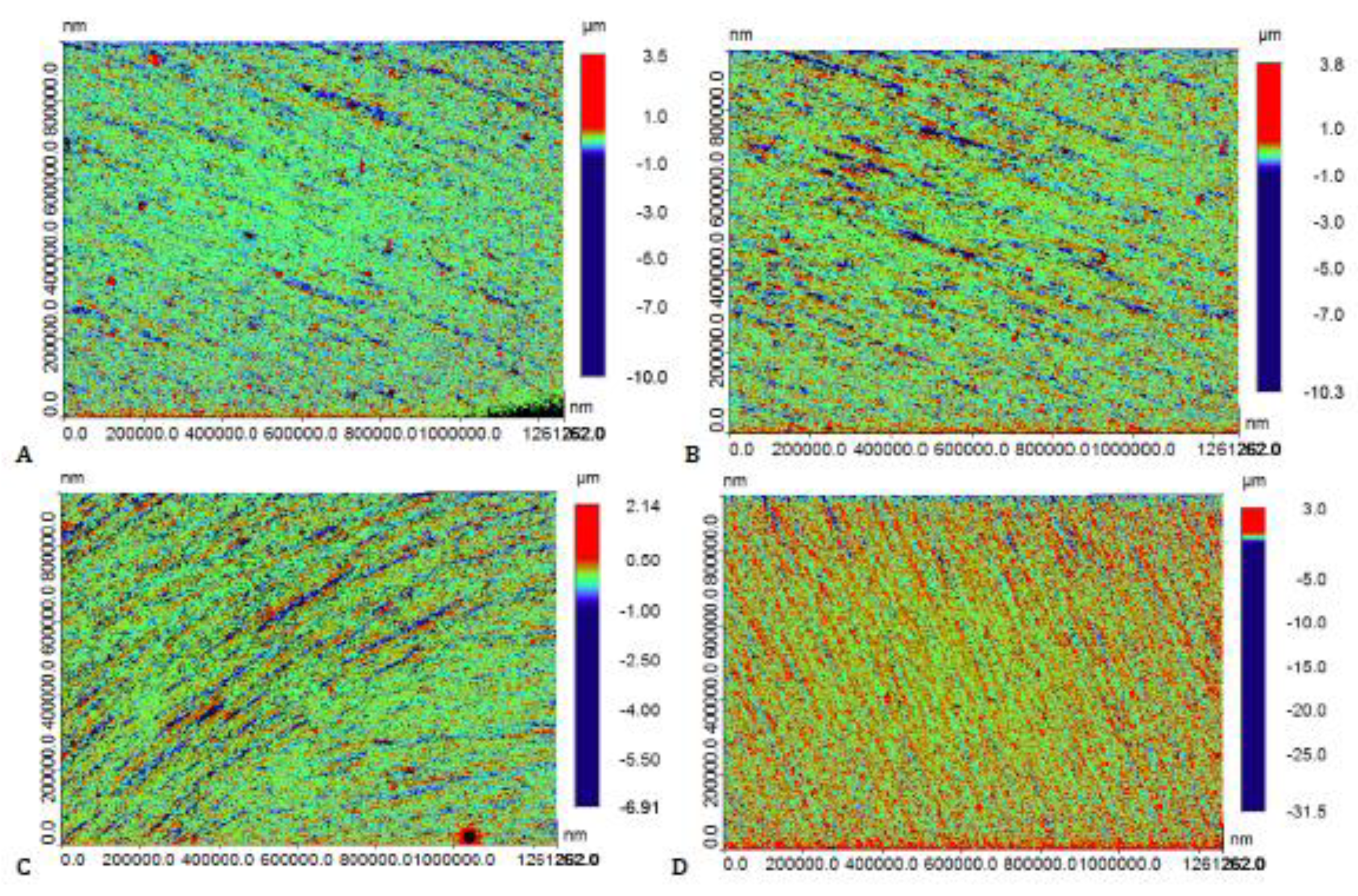
2.6. Assessment of Surface Micro Roughness (Ra)

The average surface Ra was calculated in micrometers (μm) using 3D optical non-contact laser profilometry (LPM) (Contour GT-K 3D Optical Microscope, Bruker®, Tucson, AZ, USA). The scanning parameters included magnification of 5× with a lens with a single window of 1 mm × 1 mm, 1× scan speed, and 3% thresholding. The copings were fixed horizontally on the stage using a mold fabricated with impression material (polyvinyl siloxane, 3M ESPE, St. Paul, MN, USA). The laser beam of the optical microscope was placed on the coping surface with the help of stage movement to obtain a good-quality image. The copings were scanned at five location points and an average was identified. To manage the precision and surface roughness parameters, a Vision 64 Control and Analysis Software (Bruker®, Tucson, AZ, USA) was used.

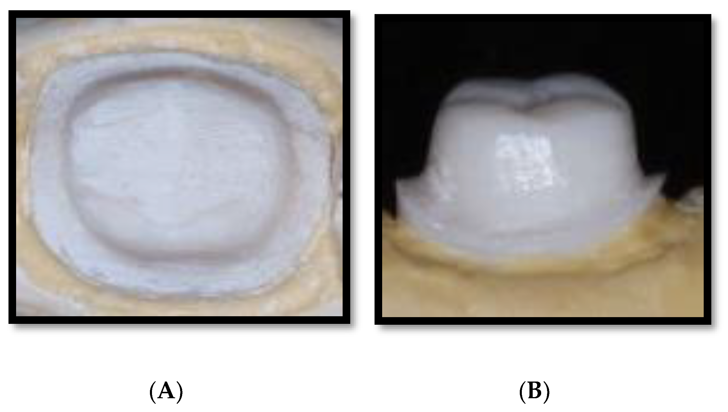
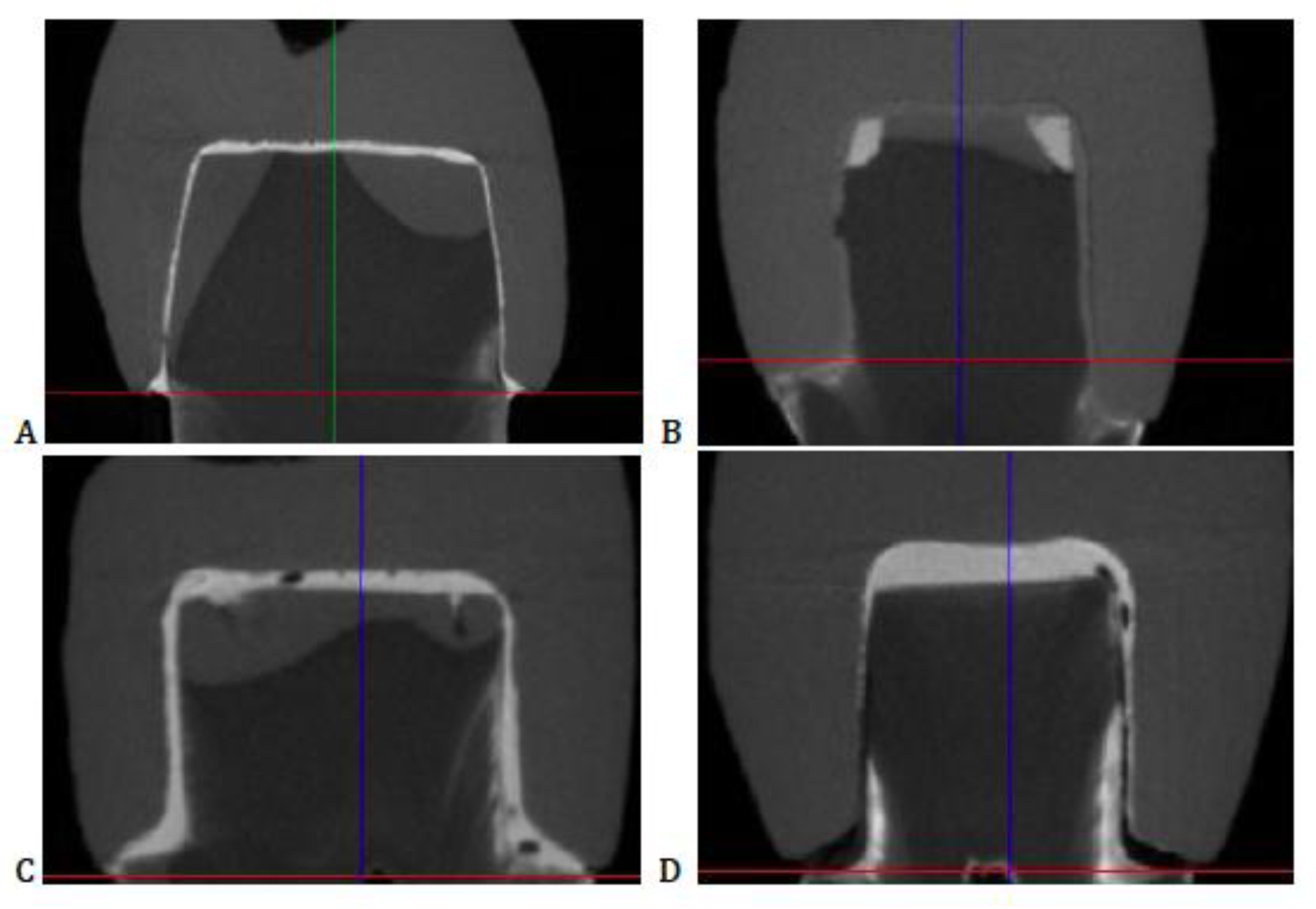
2.7. Marginal Misfit

The coping misfit was assessed in micrometer (μm). Misfit was analyzed with Bruker micro CT (Skyscan 1173 high-energy spiral scan micro-CT; Skyscan NV, Kontich, Belgium) to detect micro gaps at selected points. The coping samples were mounted and positioned inside the specimen chamber and the parameters included 130 kV of source energy at 60 µA at 300 ms of exposure time. To create a good image, a brass filter of 0.25 mm with a 0.2° rotation step for a 360° angle and 4-frame average was employed. Post scanning, reconstruction of 3D images was performed using N-Recon® software (program version 1.6.1.3, Bruker Skyscan, Kontich, Belgium). During this process, parameter adjustments were performed to enhance image quality. Reconstructed images were loaded in the Dataviewer® Software (Bruker Skyscan, Kontich, Belgium) to determine image quality and perform image misfit assessments. The measurements were preformed between the marginal surface of the coping and the prepared marginal surface of replicas of master die (Dental stone).
All assessed recordings for surface roughness and marginal misfit were logged in an Excel sheet and mean and standard deviations were evaluated. Data were analyzed using Analysis of variance (ANOVA) and Tukey Kramer multiple comparisons test. Correlation between specimen roughness and misfit was assessed using Pearson correlation. A p value of <0.05 was considered statistically significant among groups.

3. Results

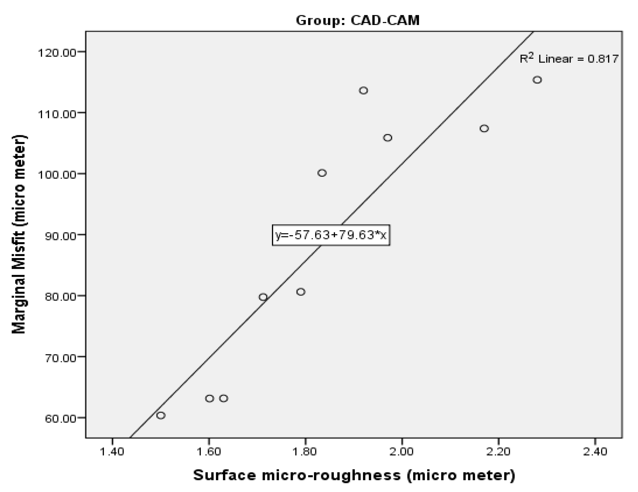
3.1. Surface Roughness

Mean and standard deviation for Ra scores of CoCr specimens after using different fabrication techniques are presented in Table 1. SLM fabricated copings displayed the highest mean values (2.251 ± 0.310 μm). Cast/LWT specimens presented the lowest mean Ra score (1.055 ± 0.184 μm). Ra values among all investigated groups were statistically significant (p < 0.05). SLM specimens showed significantly higher Ra than DLP cast copings (1.590 ± 0.167 μm) (p = 0.001). Mean Ra of Cast/LWT copings was lower than CAD-CAM (1.840 ± 0.236 μm) (p = 0.001), SLM (p = 0.001), and DLP cast (p < 0.05) specimens respectively. The micrographs obtained for surface roughness assessment are presented in Figure 2. The uniform high roughness was observed in SLM samples (2 D) and the DLP-Cast specimen displayed a smoother surface with minimal localized craters (2 C).

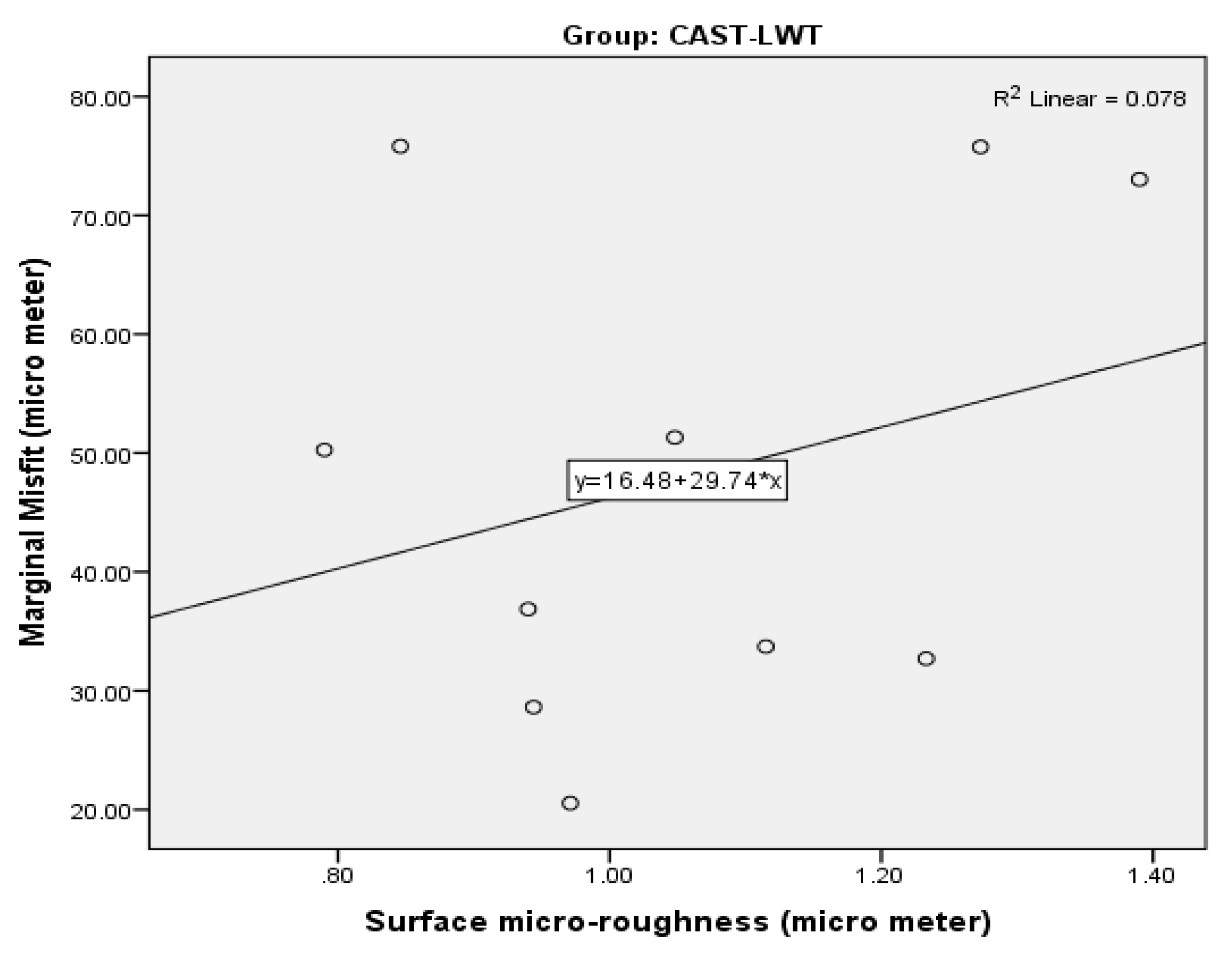
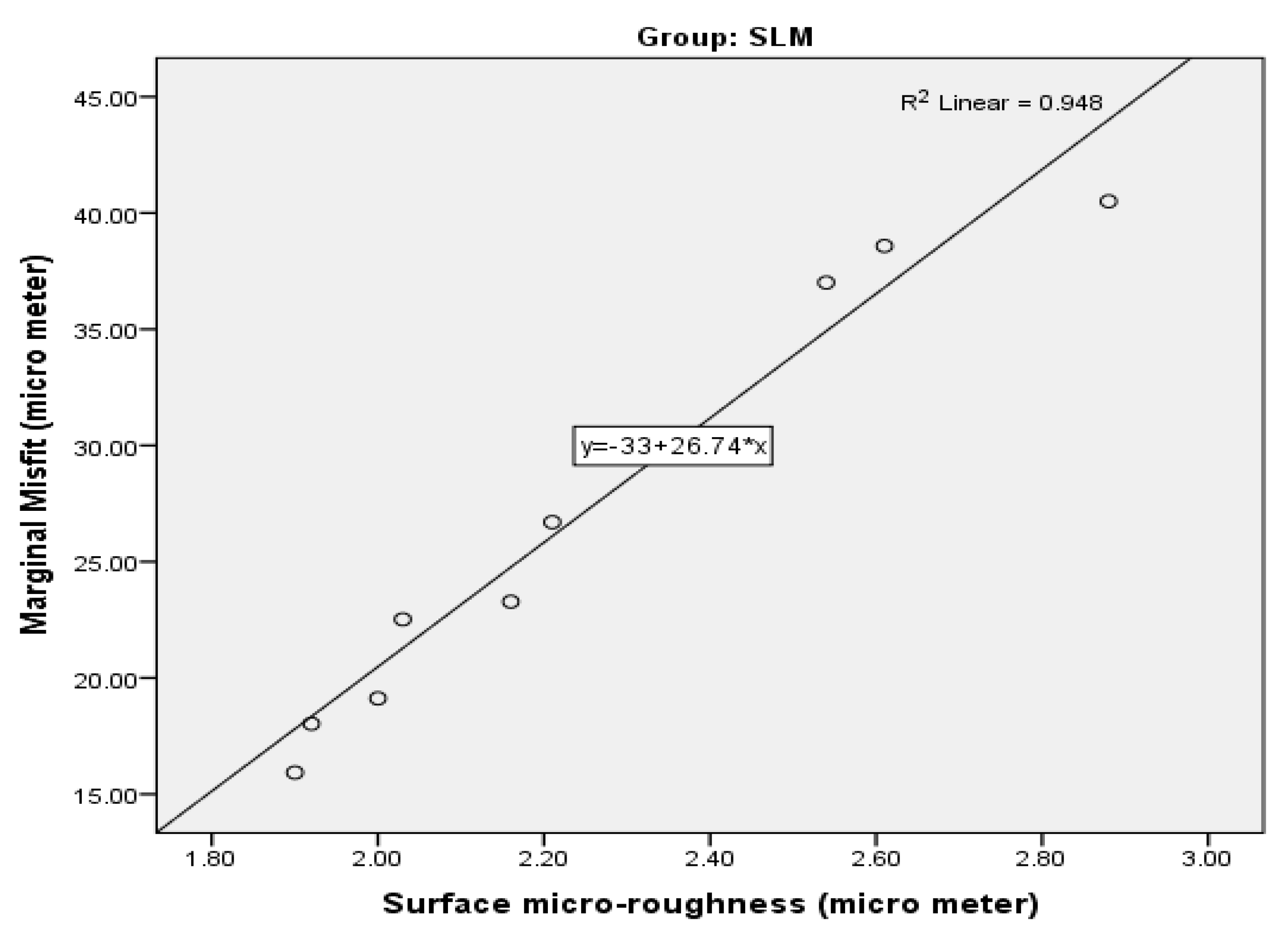
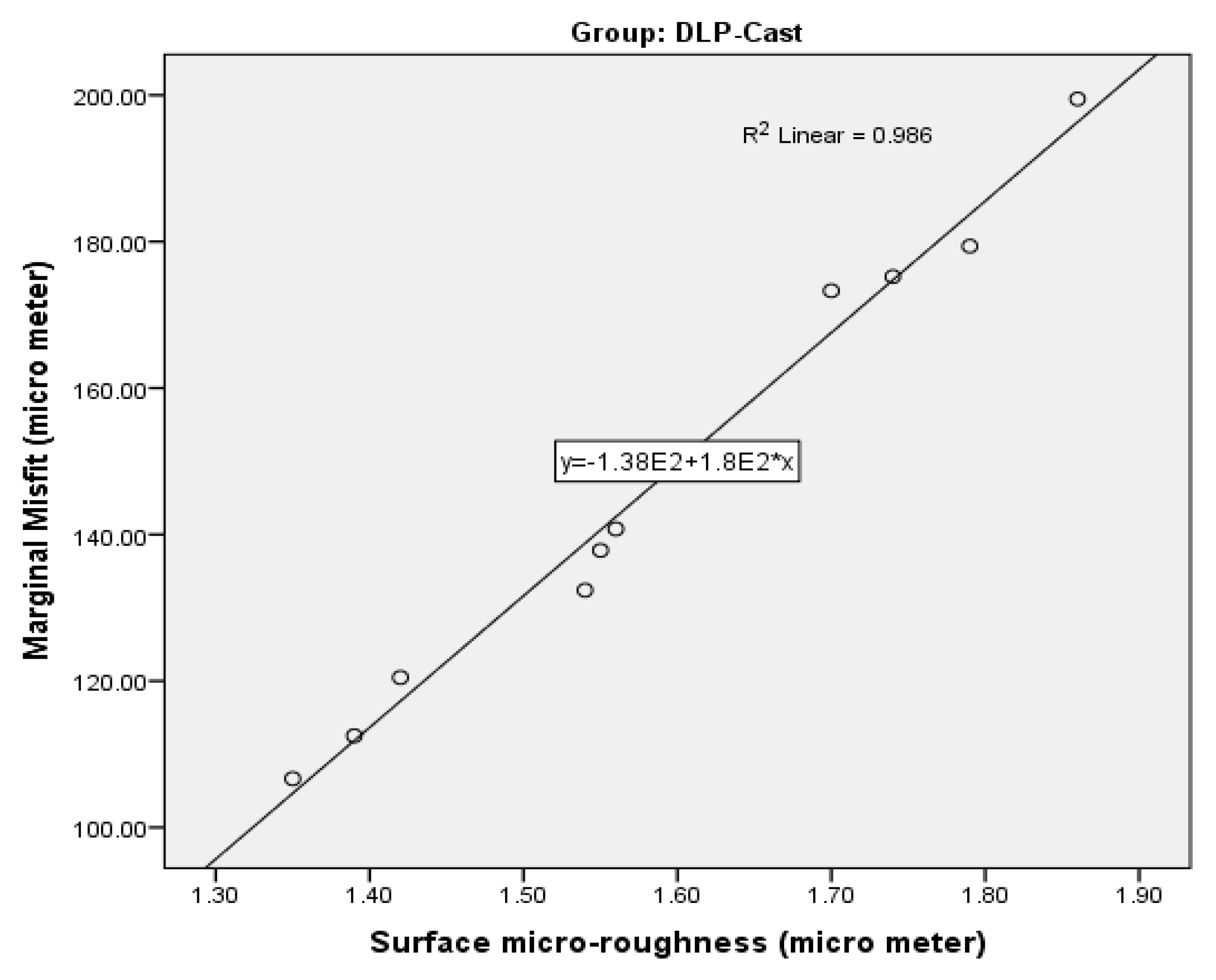
3.2. Marginal Misfit

Means and standard deviation of marginal misfit of CoCr specimens are presented in Table 2. Samples fabricated from the DLP-Cast technique demonstrated the highest mean marginal misfit (147.746 ± 30.306 μm), whereas the lowest marginal misfit was established by SLM-fabricated specimens (27.193 ± 8.519 μm). Moreover, ANOVA revealed that there was a statistically significant difference in mean marginal misfit among all investigated groups (p < 0.05). Individual intergroup comparison using Tukey Kramer post hoc test revealed that copings fabricated from the SLM technique displayed lower marginal misfit than DLP-Cast (p = 0.001) and CAD-CAM (88.943 ± 20.880 μm) (p = 0.001). However SLM copings showed higher but comparable misfits to Cast-LWT (47.861 ± 19.693 μm) samples (p > 0.05). The microCT images of the assessed samples are presented in Figure 3.
Figure 4, Figure 5, Figure 6 and Figure 7 present the correlation between Ra and marginal misfit in CAD-CAM, Cast-LWT, SLM, and DLP-Cast study samples respectively. It was observed that Ra influences the marginal misfit in CAD-CAM (81.7%), SLM (94.8%), and DLP Cast (98.6%) technique-fabricated copings. (p < 0.01). Whereas, copings which are fabricated from CAST-LWT technique did not display any significant effect of Ra on the marginal misfit on the specimens of this group (p = 0.435), as displayed in the correlation plot (Figure 5).

4. Discussion

The present in vitro study was based on the hypothesis that there is no difference on Ra and marginal misfit of CoCr copings manufactured by conventional (Cast-LWT) and contemporary techniques (CAD-CAM, SLM, DLP-Cast). However, the existing study revealed that the additive technique of SLM showed lower misfit and high roughness. Whereas, the DLP-Cast specimen displayed higher internal misfit and lower Ra than the conventional technique. Therefore, the postulated hypothesis was rejected. These outcomes can be attributed to the number of steps, scanning and software limitations, and non-optimal parameters.
Contemporary CoCr alloys have gained popularity as compared with conventional gold alloys due to improved corrosion resistance and low cost [23]. The available literature showed multiple techniques, i.e., the direct-view measurement technique, the silicone replica technique, and cross-sectioning to measure the marginal misfit of fabricated copings [26]. The micro-computed tomography (CT), on the other hand, is comparatively an advanced method to assess the fit of indirect restoration through processing of scanned specimens slices, reconstructing the assembly by using software and gaging the misfit [27]. Similarly, in the present study the LPM was used to evaluate the Ra of CoCr copings. It is an optical system which is used to scan comparatively larger surface areas. It exhibits advantages over other techniques, i.e., determining surface characteristics such as the height of the largest profile projection and the depth of the largest profile depression [28].
In the present study it was found that SLM fabrication technique displayed lower marginal misfit than the other investigated groups. The better performance of the SLM technique is in line with the results of the study conducted by Fathi et al. [29]. Although, in the study by Fathi et al., assessments were performed using a silicone impression technique [29]. This can be explained by the fact that a lesser number of steps involved in the technique contributes to the precisely fitting copings as compared to other tested techniques. Moreover, copings fabricated from Cast-LWT displayed higher marginal misfit as compared with SLM copings. Multiple factors explain the increased misfit of Cast-LWT compared with SLM samples. Multiple steps are involved in the production of prosthesis through Cast-LWT and each step poses a risk of incorporating error thus compromising prosthetic fit [16]. Moreover, the accuracy of cast coping obtained through Cast-LWT depends on the accuracy of wax pattern and technical accuracy, i.e., wax composition, tank and block temperature, time specified for cooling of the wax pattern, and the firing temperature necessary to achieve desirable outcomes [30]. In addition, distortion of inlay casting wax, its shrinkage, and high investment expansion affects the precision of copings fabricated with Cast-LWT [31].
In the present study, DLP-Cast copings exhibited the highest marginal misfit compared with all other techniques. Marginal fit is highly dependent on the material properties utilized to fabricate copings in the 3D printer [32]. Moreover, resin used in the DLP-Cast technique undergoes polymerization shrinkage which generates stress, resulting in distortion of internal and marginal misfit [33]. In addition, the effect of scan spray when scanning the models cannot be overlooked [4]. These findings are in accordance with the study conducted by Kim at el., which used M-One printer, resulting in greater marginal misfit of DLP-Cast than other groups tested [25]. Kim et al. assessed the misfit using the weight of the silicone material and a digital microscope with sectioned specimens. Furthermore, it was also found that CAD-CAM displayed a significantly higher marginal misfit compared with Cast-LWT and SLM copings. This may be because correctness of internal and the marginal fit of copings produced through the subtractive technique depends on bur size. Any discrepancy in selection and size of burs relative to the size of coping results in compromised marginal properties [34]. Moreover, scanning and software system limitations related to finite resolution plausibly explicate the findings as these might result in margins with lower fit accuracy [35]. Many studies have compared the marginal or internal fit of coping and crowns fabricated from CAD-CAM and Cast-LWT [5,12,36]. Yet, it is challenging to conclude the findings of those studies due to variations in sample size, methods adopted to measure the marginal or internal gap, the type of cement used, and the CAD-CAM systems chosen. However, results of multiple previous studies are in line with the finding of the present study and displayed larger marginal or internal misfit for CAD-CAM fabricated prostheses than conventional techniques [12,37,38].
The influence of the different fabrication techniques on the Ra of CoCr copings have been addressed, proposing that Ra varies with the type of manufacturing technique [30]. Available literature also suggested that Ra values of any indirect prosthesis should be at least 0.2 µm [39]. Ra is suggested to influence retention of restorations, but its effect on the marginal fit is not clear. In the present study, it was found that all fabrication techniques demonstrated Ra higher than the recommended threshold. Moreover, the difference in Ra values among different AM techniques, i.e., DLP-Cast and SLM, can be explained by different parameters adopted during fabrication [40]. It is suggested that the use of non-optimal parameters in any of the AM techniques result in porosity and an increase in the Ra of the prosthesis [41]. In the authors’ opinion, decreased marginal misfit in SLM-fabricated copings may be due to the highest surface roughness obtained in this group. Similarly, surface roughness of copings fabricated from the CAD-CAM subtractive technique depends on the cutting speed and depth of the cutting [42]. Moreover, LWT copings displayed the lowest Ra score; this may be due to the favorable inlay wax surface properties along with strict adherence to manufacturer guidelines aiding low Ra [43].
The study showed that additive manufacturing methods like SLM and DLP-cast showed varying success in producing marginally accurate and smooth metal copings. The findings suggest that SLM copings have a good marginal fit and high roughness; however, DLP-Cast specimens display low roughness but a poor marginal fit. Therefore, both of these techniques need further development and can only be applied in limited clinical contexts. The findings of the study should be interpreted in light of the possible study limitations. In the present study, copings were manufactured under ideal circumstances and controlled conditions. In addition, the outcomes of the study are limited to the materials and techniques employed in the experiments. Therefore, to translate the findings of the present study into clinical recommendations, randomized clinical trials assessing the fit and adaptation of CoCr copings fabricated with additive manufacturing techniques are warranted.

5. Conclusions

The SLM technique showed an improved coping marginal fit, but high roughness compared with controls. By contrast, the DLP-Cast specimens had smooth surfaces with poor marginal fits. Therefore, the application of additive manufacturing methods (SLM and DLP-Cast) in the fabrication of CoCr metal alloy coping needs further development.

Author Contributions

Conceptualization, A.S.A., F.V., T.A. and S.A.-S.; methodology, A.S.A., A.A., T.A. and M.E.; validation, A.S.A., S.A.-S., A.A., M.E. and M.K.A.; formal analysis, A.A., A.S.A., T.A., M.K.A. and M.E.; investigation, A.S.A., T.A., M.K.A., M.E., A.M.A. and F.V.; resources, T.A., S.A. and A.M.A.; data curation, M.K.A., S.A. and F.V.; writing—original draft preparation, F.V., S.A.-S. and S.A.; writing—review and editing, T.A., A.M.A. and A.A.; supervision, F.V., T.A. and A.S.A.; funding acquisition, T.A. All authors have read and agreed to the published version of the manuscript.

Funding

The authors are grateful to the Researchers supporting project at King Saud University for funding through Researchers supporting project No. (RSP-2019-44).

Institutional Review Board Statement

No ethical approval was required as patients or human or animal tissues were not involved in the study.

Informed Consent Statement

Not applicable.

Data Availability Statement

The data is available on contact from the corresponding author.

Acknowledgments

The authors are grateful to the Researchers supporting project at King Saud University for funding through Researchers supporting project No. (RSP-2019-44).

Conflicts of Interest

The authors declare no conflict of interest.

References

  1. Vohra, F.; Bin Ismail, I.H.; Al-Rifaiy, M.Q.; Abduljabbar, T.; Abualsaud, H.; Ali, M.; Abu Hasan, M.I. Influence of veneering technique and veneer-coping thickness on fracture toughness of implant retained veneered Y-TZP zirconia crowns. J. Adhes. Sci. Technol. 2017, 31, 1758–1767. [Google Scholar] [CrossRef]
  2. Samer, M.S.; Faraz, Q.; Al-Dubai, S.A.R.; Vohra, F.; Abdullah, H.; Taiyeb-Ali, T.B.; Saub, R. Clinical outcomes and predictors of satisfaction in patients with improved lithium disilicate all-ceramic crowns. Med. Princ. Pract. 2017, 26, 470–479. [Google Scholar] [CrossRef] [PubMed] [Green Version]
  3. Al-Aali, K.A.; Bin-Shuwaish, M.S.; Alhenaki, A.M.; Al Ahdal, K.; Al Deeb, L.; Maawadh, A.M.; AlHelal, A.; Alshehri, H.; Vohra, F.; Abduljabbar, T. Influence of milling systems and marginal configurations on the fit of yttrium stabilized tetragonal zirconia polycrystals (Y-TZP)’copings. J. Appl. Biomater. Funct. Mater. 2020, 18, 2280800020924514. [Google Scholar]
  4. Al-Aali, K.A.; Alhamdan, R.S.; Maawadh, A.M.; Vohra, F.; Abduljabbar, T. Influence of contemporary CAD-CAM milling systems on the fit and adaptation of partially stabilized Zirconia fixed partial dentures. Pak. J. Med. Sci. 2021, 37, 45–49. [Google Scholar] [PubMed]
  5. Al Deeb, L.; Al Ahdal, K.; Alotaibi, G.; Alshehri, A.; Alotaibi, B.; Alabdulwahab, F.; Al Deeb, M.; AlFawaz, Y.F.; Vohra, F.; Abduljabbar, T. Marginal Integrity, Internal Adaptation and Compressive Strength of 3D Printed, Computer Aided Design and Computer Aided Manufacture and Conventional Interim Fixed Partial Dentures. J. Biomater. Tissue Eng. 2019, 9, 1745–1750. [Google Scholar] [CrossRef]
  6. Bin-Shuwaish, M.; AlFawaz, Y.F.; AlGamaiah, H.A.; AlSani, A.S.; Abobakr, I.B.; Alzahrani, K.M.; Almutairi, B.; Attar, E.A.; Vohra, F.; Abduljabbar, T. Technical accuracy of dental laboratories in the quality and shade matching of porcelain fused to metal crowns: An in vitro study. Int. J. Environ. Res. Public Health 2021, 18, 2722. [Google Scholar] [CrossRef]
  7. Hunt, L.B. The long history of lost wax casting—Over five thousand years of art and craftsmanship. Gold Bull. 1980, 13, 63–79. [Google Scholar] [CrossRef] [Green Version]
  8. Vohra, F.; Shuwaish, M.B.; Al Deeb, M.; Alhamdan, R.; Alotaibi, N.; Abduljabbar, T. Comparison of failure loads and compressive stress in Press on metal and Press on Y-TZP copings. Pak. J. Med. Sci. 2020, 36, 1645–1650. [Google Scholar] [CrossRef] [PubMed]
  9. McCoy, T. Lost wax casting technique for metal crown fabrication. J. Vet. Dent. 2014, 31, 126–132. [Google Scholar] [CrossRef] [PubMed]
  10. Carrabba, M.; Vichi, A.; Vultaggio, G.; Pallari, S.; Paravina, R.; Ferrari, M. Effect of finishing and polishing on the surface roughness and gloss of feldspathic ceramic for chairside CAD/CAM systems. Oper. Dent. 2017, 42, 175–184. [Google Scholar] [CrossRef]
  11. Rödiger, M.; Schneider, L.; Rinke, S. Influence of material selection on the marginal accuracy of CAD/CAM-fabricated metal- And all-ceramic single crown copings. BioMed Res. Int. 2018, 2018, 2143906. [Google Scholar] [CrossRef]
  12. Ahrberg, D.; Lauer, H.C.; Ahrberg, M.; Weigl, P. Evaluation of fit and efficiency of CAD/CAM fabricated all-ceramic restorations based on direct and indirect digitalization: A double-blinded, randomized clinical trial. Clin. Oral Investig. 2016, 20, 291–300. [Google Scholar] [CrossRef]
  13. Rajan, B.N.; Jayaraman, S.; Kandhasamy, B.; Rajakumaran, I. Evaluation of marginal fit and internal adaptation of zirconia copings fabricated by two CAD—CAM systems: An in vitro study. J. Indian Prosthodont. Soc. 2015, 15, 173–178. [Google Scholar] [CrossRef] [PubMed]
  14. Mansour, F.K.; Ibrahim, R.M.; Mansour, H.; Hamdy, A.M. Assessment of internal fit and micro leakage of conventionally fabricated ceramometallic restoration versus CAD wax and press veneering (in-vitro study). BDJ Open 2021, 7, 17. [Google Scholar] [CrossRef]
  15. Farjood, E.; Vojdani, M.; Torabi, K.; Khaledi, A.A.R. Marginal and internal fit of metal copings fabricated with rapid prototyping and conventional waxing. J. Prosthet. Dent. 2017, 117, 164–170. [Google Scholar] [CrossRef] [PubMed]
  16. Lövgren, N.; Roxner, R.; Klemendz, S.; Larsson, C. Effect of production method on surface roughness, marginal and internal fit, and retention of cobalt-chromium single crowns. J. Prosthet. Dent. 2017, 118, 95–101. [Google Scholar] [CrossRef] [PubMed] [Green Version]
  17. Zocca, A.; Colombo, P.; Gomes, C.M.; Günster, J. Additive Manufacturing of Ceramics: Issues, Potentialities, and Opportunities. J. Am. Ceram. Soc. 2015, 98, 1983–2001. [Google Scholar] [CrossRef]
  18. Gholamrezaei, K.; Vafaee, F.; Afkari, B.F.; Firouz, F.; Seif, M. Fit of cobalt-chromium copings fabricated by the selective laser melting technology and casting method: A comparative evaluation using a profilometer. Dent. Res. J. 2020, 17, 200–207. [Google Scholar]
  19. Ren, L.; Memarzadeh, K.; Zhang, S.; Sun, Z.; Yang, C.; Ren, G.; Allaker, R.P.; Yang, K. A novel coping metal material CoCrCu alloy fabricated by selective laser melting with antimicrobial and antibiofilm properties. Mater. Sci. Eng. C 2016, 67, 461–467. [Google Scholar] [CrossRef] [Green Version]
  20. Li, X.; Zhong, H.; Zhang, J.; Duan, Y.; Li, J.; Jiang, D. Fabrication of zirconia all-ceramic crown via DLP-based stereolithography. Int. J. Appl. Ceram. Technol. 2019, 17, 844–853. [Google Scholar] [CrossRef]
  21. Chen, Z.; Li, Z.; Li, J.; Liu, C.; Lao, C.; Fu, Y.; Liu, C.; Li, Y.; Wang, P.; He, Y. 3D printing of ceramics: A review. J. Eur. Ceram. Soc. 2019, 39, 661–687. [Google Scholar] [CrossRef]
  22. Pettenò, D.; Schierano, G.; Bassi, F.; Bresciano, M.E.; Carossa, S. Comparison of Marginal Fit of 3 Different Metal-Ceramic Systems: An In Vitro Study. Int. J. Prosthodont. 2001, 13, 405–408. [Google Scholar]
  23. Kim, M.-J.; Choi, Y.-J.; Kim, S.-K.; Heo, S.-J.; Koak, J.-Y.; Weber, F.E. Marginal Accuracy and Internal Fit of 3-D Printing Laser-Sintered Co-Cr Alloy Copings. Materials 2017, 10, 93. [Google Scholar] [CrossRef] [PubMed] [Green Version]
  24. Zeltser, C.; Lewinstein, I.; Grajower, R. Fit of crown wax patterns after removal from the die. J. Prosthet. Dent. 1985, 53, 344–346. [Google Scholar] [CrossRef]
  25. Venkatesh, K.V.; Nandini, V.V. Direct metal laser sintering: A digitised metal casting technology. J. Indian Prosthodont. Soc. 2013, 13, 389–392. [Google Scholar] [CrossRef]
  26. Ram, S.; Ranadive, N.; Nadgere, J. Microcomputed tomography a noninvasive method to evaluate the fit of a restoration as compared to conventional replica technique. J. Indian Prosthodont. Soc. 2019, 19, 233–239. [Google Scholar] [CrossRef]
  27. Pelekanos, S. Micro-CT evaluation of the marginal fit of different In-Ceram alumina copings. Eur. J. Esthet. Dent. Off. J. Eur. Acad. Esthet. Dent. 2009, 4, 278–292. [Google Scholar]
  28. Kulik, E.A.; Calahan, P. Laser Profilometry of Polymeric Materials. Cells Mater. 1997, 7, 3. [Google Scholar]
  29. Fathi, H.M.; Al-Masoody, A.; Johnson, A. The accuracy of fit of crowns made from wax patterns produced conventionally (hand formed) and via CAD/CAM technology. Eur. J. Prosthodont. Restor. Dent. 2016, 24, 10–17. [Google Scholar] [CrossRef] [PubMed]
  30. Sravani, K. To Evaluate And Compare The marginal fit and internal adaptation of cast copings fabricated with pattern wax and autopolymerized pattern resin materials. IOSR J. Dent. Med Sci. (IOSR-JDMS) 2020, 19, 54–66. [Google Scholar]
  31. Oguz, E.I.; Kılıçarslan, M.A.; Özgür, M.E.; Orhan, K.; Shujaat, S. Comparison of Marginal Adaptation of Different Resin-Ceramic CAD/CAM Crowns: An In Vitro Study. J. Adv. Oral Res. 2021, 12, 112–118. [Google Scholar] [CrossRef]
  32. Cui, K.; Shang, X.; Luo, C.; Shen, Z.; Gao, H.; Xiong, G. A kind of accuracy improving method based on error analysis and feedback for DLP 3D Printing. In Proceedings of the IEEE international conference on service operations and logistics, and Informatics 2019 (SOLI 2019), Zhengzhou, China, 6–8 November 2019; pp. 5–9. [Google Scholar]
  33. Kim, S.Y.; Shin, Y.S.; Jung, H.D.; Hwang, C.J.; Baik, H.S.; Cha, J.Y. Precision and trueness of dental models manufactured with different 3-dimensional printing techniques. Am. J. Orthod. Dentofac. Orthop. 2018, 153, 144–153. [Google Scholar] [CrossRef] [Green Version]
  34. Guncu, M.B.; Tuba Akcin, E.; Aktas, G.; Aslan, Y. Accuracy of CAD CAM manufacturing techniques on marginal and internal fit of 5-unit implant-supported Co-Cr frameworks. Clin. Oral Implants Res. 2018, 29, 162. [Google Scholar] [CrossRef] [Green Version]
  35. Davidowitz, G.; Kotick, P.G. The Use of CAD/CAM in Dentistry. Dent. Clin. N. Am. 2011, 55, 559–570. [Google Scholar] [CrossRef]
  36. Tan, P.L.; Gratton, D.G.; Diaz-Arnold, A.M.; Holmes, D.C. An in vitro comparison of vertical marginal gaps of CAD/CAM titanium and conventional cast restorations. J. Prosthodont. 2008, 17, 378–383. [Google Scholar] [CrossRef]
  37. Pompa, G.; Di Carlo, S.; De Angelis, F.; Cristalli, M.P.; Annibali, S. Comparison of conventional methods and laser-assisted rapid prototyping for manufacturing fixed dental prostheses: An In vitro study. BioMed Res. Int. 2015, 2015, 318097. [Google Scholar] [CrossRef] [Green Version]
  38. Alves de Carvalho, I.; Marques, T.; Araújo, F.; Azevedo, L.; Donato, H.; Correia, A. Clinical Performance of CAD/CAM Tooth-Supported Ceramic Restorations: A Systematic Review. Int. J. Periodontics Restor. Dent. 2018, 38, e68–e78. [Google Scholar] [CrossRef]
  39. Bollen, C.M.; Lambrechts, P.; Quirynen, M. Comparison of surface roughness of oral hard materials to the threshold surface roughness for bacterial plaque retention: A review of the literature. Dent. Mater. 1997, 13, 258–269. [Google Scholar] [CrossRef]
  40. Pleass, C.; Jothi, S. Influence of powder characteristics and additive manufacturing process parameters on the microstructure and mechanical behaviour of Inconel 625 fabricated by Selective Laser Melting. Addit. Manuf. 2018, 24, 419–431. [Google Scholar] [CrossRef]
  41. Abate, K.M.; Nazir, A.; Chen, J.E.; Jeng, J.Y. Design, optimization, and evaluation of additively manufactured vintiles cellular structure for acetabular cup implant. Processes 2020, 8, 25. [Google Scholar] [CrossRef] [Green Version]
  42. Koizumi, H.; Saiki, O.; Nogawa, H.; Hiraba, H.; Okazaki, T.; Matsumura, H. Surface roughness and gloss of current CAD/CAM resin composites before and after toothbrush abrasion. Dent. Mater. J. 2015, 34, 881–887. [Google Scholar] [CrossRef] [PubMed] [Green Version]
  43. Vaidya, S.; Parkash, H.; Bhargava, A.; Gupta, S. Evaluation of the marginal fit of metal copings fabricated on three different marginal designs using conventional and accelerated casting techniques: An in vitro study. Indian J. Dent. Res. 2014, 25, 641–647. [Google Scholar] [CrossRef] [PubMed]
Figure 1. Representative image of the prepared tooth specimen. Prepared tooth (A) Occlusal, (B) Buccal.
Applsci 11 08328 g001
Figure 2. Surface roughness (Ra) micrographs for groups (A) Cast/LWT, (B) CAD-CAM, (C) DLP-Cast, and (D) SLM.
Applsci 11 08328 g002
Figure 3. MicroCT images of the assessed samples in groups (A) Cast/LWT, (B) CAD-CAM, (C) DLP-Cast, and (D) SLM.
Applsci 11 08328 g003
Figure 4. Showing a positive correlation between surface micro roughness and marginal misfit in CAD-CAM samples. R2 showed 81.7% variation in marginal misfit explained by surface micro roughness; p-value was less than 0.01, and therefore statistically significant.
Applsci 11 08328 g004
Figure 5. Showing a positive correlation between surface micro roughness and marginal misfit in CAST-LWT samples. R2 showed 7.8% variation in marginal misfit explained by surface micro roughness; p-value 0.435, and therefore statistically insignificant.
Applsci 11 08328 g005
Figure 6. Showing a positive correlation between surface micro roughness and marginal misfit in SLM samples. R2 showed 94.8% variation in marginal misfit explained by surface micro roughness; p-value was less than 0.01, and therefore statistically significant.
Applsci 11 08328 g006
Figure 7. Showing a positive correlation between surface micro roughness and marginal misfit in DLP Cast samples. R2 showed 98.6% variation in marginal misfit explained by surface micro roughness; p-value was less than 0.01, and therefore statistically significant.
Applsci 11 08328 g007
Table 1. Comparison of surface micro-roughness of the CoCr copings.
Study GroupMean (μm)SDANOVA p ValueCast/LWTCAD-CAMSLMDLP-Cast
Cast/LWT1.0550.1840.001 $1.000
CAD-CAM1.8400.2360.001 *1.000
SLM2.2510.3100.001 *0.038 *1.000
DLP-Cast1.5900.1670.0280.0570.001 *1.000
* Statistical significant difference using Tukey Kramer post hoc test; $ Statistical significant difference using ANOVA.
Table 2. Comparison of marginal misfit of the CoCr copings.
Study GroupMean (μm)SDANOVA
p Value
Cast/LWTCAD-CAMSLMDLP-Cast
Cast/LWT47.86119.6930.001 $1.000
CAD-CAM88.94320.8800.031 *1.000
SLM27.1938.5190.0740.001 *1.000
DLP-Cast147.74630.3060.013 *0.001 *0.001 *1.000
* Statistical significant difference among groups shown in corresponding rows and columns using Tukey Kramer post hoc test; $ Statistically significant difference using ANOVA.
Publisher’s Note: MDPI stays neutral with regard to jurisdictional claims in published maps and institutional affiliations.

